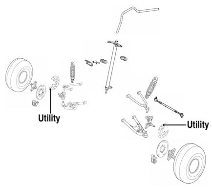
Steering/Frame/Controls The following steering components should be inspected periodically to ensure safe and proper operation. A. Handlebar grips not worn, broken, or loose. B. Handlebar not bent or cracked and has equal and complete full-left and full-right capability. C. Steering post bearing assembly/bearing housing not broken, worn, or binding. KM189A
D. Ball joints not worn, cracked, or damaged.
3. Lift the handlebar out of the lower handlebar holders and lay the handlebar forward.
E. Tie rods not bent or cracked.
4. Remove the cotter pins and slotted nuts securing the tie rod ends to the steering post arm; then disconnect the tie rods from the arm.
F. Knuckles not worn, cracked, or damaged. G. Cotter pins not damaged or missing. The frame, welds, and racks should be checked periodically for damage, bends, cracks, deterioration, broken components, and missing components.
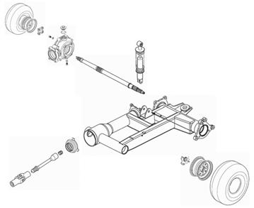
Steering Post/Tie Rods
KM590
5. Remove the cotter pin and slotted nut from the lower end of the steering post; then remove the upper steering shaft support block. Account for a cable guide, two steering support blocks, and the upper steering post bushing. .
KM598E
REMOVING 1. On the Utility, remove the front rack and front center panel (see Body in this section). On the DVX, proceed to step 2. 2. Remove the steering post cover (DVX) or the instrument pod (Utility) (see Steering Post Cover/Instrument Pod in this section); then remove the cap screws securing the handlebar to the steering post. Account for two handlebar holders.
106
Manual Table of Contents
KM588