2 minute read
Oil Inlet Tube " 0 " Retaining Nuts Ring 54. C om pressor-to-


HEEL
DRIVE SIDE (CONVEX) HEEL
COAST SIDE (CONCAVE)
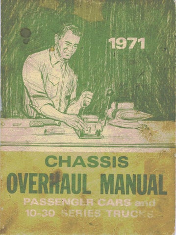
Fig. 20B~G ear Tooth Nom enclature
2. Use gear marking compound and apply this mixture sparingly to all ring gear teeth using a medium stiff brush. W hen properly used, the area of pinion tooth contact will be visible when hand load is applied. 3. Tighten bearing cap bolts to 55 lb. ft. 4. Expand brake shoes until a torque of 40-50 lb. ft. is required to turn the pinion.
NOTE: A test made without loading the gears will not give a satisfactory pattern. Turn companion flange w ith wrench so that ring gear rotates one full revolution then reverse rotation so that ring gear rotates one revolution in opposite direction. Excessive turning of ring gear may indicate good tooth pattern because one or two teeth are making proper contact.
5. Observe pattern on ring gear teeth and compare with
Figures 20B and 2 IB.
E ffe c t s of In cre a sin g Load on Tooth C o n ta c t P attern
W hen "load" on ring and pinion gear is increased, such as when car is accelerated forward from standstill or from normal drive, the tooth contact will tend to spread out, and under very heavy load will extend from near toe to near heel on the drive side. The entire contact also tends to shift toward heel under increasingly heavier loads and will become somewhat broader with respect to tops and bottoms of teeth. The patterns obtained by tooth pattern tests, dependent upon degree of "loading", approximate a normal light load. For this reason, they will extend only about halfway.
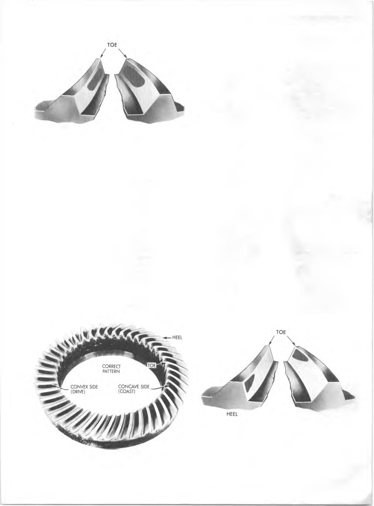
The im portant thing to note is that the contact pattern is centrally located up and down on the face of the ring gear teeth.
A d ju stm e n ts A ffe c tin g Tooth C o n ta ct
Two adjustments can be made which will affect tooth contact pattern, backlash, and position of drive pinion in carrier. The effects of bearing preloads are not readily apparent on (hand loaded) teeth pattern tests; however, these adjustm ents should be within specifications before proceeding with backlash and drive pinion adjustments.
Backlash is adjusted by means of the side bearing adjusting shims which moves the entire case and ring gear assembly closer to, or farther from the drive pinion. (The adjusting shims are also used to set side bearing preload).
The position of the drive pinion is adjusted by increasing or decreasing the shim thickness between the pinion head and inner race of rear bearing. The shim is used in the differential to compensate for m anufacturing tolerances. Increasing shim thickness will move the pinion closer to centerline of the ring gear. Decreasing shim thickness will move pinion farther away from centerline of the ring gear.
E ffe c ts of Pinion Position on Tooth Pattern
W hen the drive pinion is too far away from centerline of the ring gear, the pattern will be a high heel contact on drive
Fig. 21B~Desired Tooth C ontact Under Light Load HEEL
DRIVE SIDE COAST SIDE (CONVEX) (CONCAVE)
Fig. 2 2 B -T o o th P attern -P inio n too Far A w ay from Ring Gear (Insufficie nt Shim Thickness)