2 minute read
Axle Shaft Guide


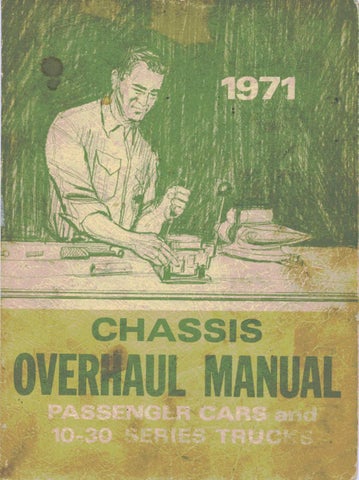
DIAL INDICATOR J-6266-31 (HEAVY DUTY ONLY)
PLUNGER
Fig. 13A --lnstalled V ie w of Pinion Depth Gauge
Light-duty axle-position gauge plate with lower surface (x stam ped near low side) tow ard top of carrier.
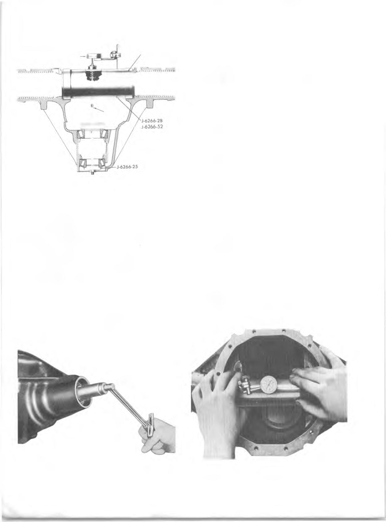
Heavy-duty axle-position gauge plate with higher surface tow ard top of carrier. d. Insert clamp screw through gauge plate and both of the pinion bearings. e. Position J-6266-25 on threaded end of clamp screw and index it in front bearing, install hex nut and rotate bearings several times to make sure that they are seated. 8. Continue with the following steps for both passenger and truck. f. Tighten hex nut until 20 in lbs. of torque is required to rotate bearings (fig. 14A). g. A fter torque has been established check position of gauge plate in carrier (See Steps b and c). h. Position dial indicator (Tool J-8001-3) on gauge post of Tool J- 6266-28 so that indicator button rests on top of tool plunger. i. Position Tool J-6266-28 in carrier as shown in Figure 15A. Swing tool body so that plunger does not touch gauge plate, and set indicator dial at zero.
NOTE: Barrel Adapters Tool J-6266-31 must be used when gauging heavy- duty axle. Make sure adapters are seated in differential bearing bores of carrier before measuring depth.
j. Slowly swing inner end of tool plunger across gauge plate until highest indicator reading is obtained. Record this measurement and recheck to see that it is correct. k. All service pinion gears are stamped with a code num ber on the threaded end of the pinion. The numerical difference between the code number and the gauge reading obtained in Step i determines the required thickness of the pinion locating shim. EXAM PLE: Pinion Code N um ber................................... 45 Dial Indicator R e a d in g ............................... 16 D ifference........................................................ 29 Proper Shim T h ick n ess...................................029”
NOTE: Shims are available in .001" increments from .021" to .037". Each shim has the thickness etched on flat surface for easy identification.
9. Remove Tool J-6266 and pinion bearing cone and roller assemblies from carrier. 10. Position shim selected in above procedure on pinion shaft and against pinion head. 11. Install new cone and roller assembly, using Tool J-5590 for lightduty axle (fig. 16A) or Tool J-9772 for heavy- duty axle (fig. 17A). Press cone against shim and rear face of pinion.
Fig. 14 A -M e a su rin g Drive Pinion Bearing Rotating Torque Fig. 15 A -M e a su rin g Drive Pinion Shim Requirem ent