2 minute read
Piston Ring Tube Rear " 0 " Ring


Fig. 2 2 A -D e te rm in in g Service Shim Size
6. Tighten lock bolt on side of the tool then remove tool.
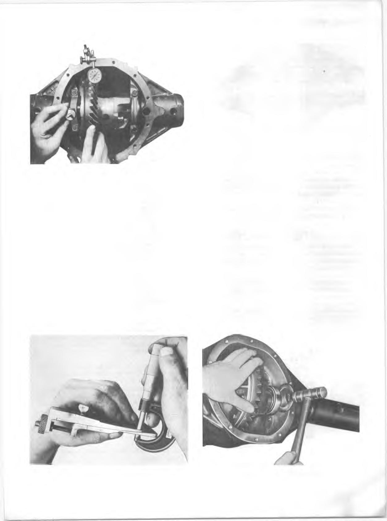
7. Using a micrometer, measure the thickness of the gauging plates in a minimum of three places (fig. 2 3 A).
Average these readings and record result.
8. T urn ring gear 90 degrees and repeat Steps 5, 6 and 7.
9. T he thickness o f the service shim is d eterm in ed by su b tractin g the thickness o f the service spacer from the h ig h er o f the tw o av erag ed rea d in g s o b ta in e d in step s 7 a n d 8. E X A M P L E : G aug e thickness (higher re a d in g )...................... 254" Service spacer used Service shim size (left sid e )..................................084" 10. Install the selected shim between the service spacer and bearing. Remove strap J-22779-6 and install left bearing cap. Torque bearing cap bolts to specifications. 11. Remove right-hand bearing cap and install Tool J- 22779 between right bearing cup and carrier housing. 12. Turn adjusting nut clockwise while oscillating tool until a noticeable drag is produced (bearing outer race rotates with tool). Remove tool and measure the thickness of the gauging plate in a minimum of three places (fig. 23A). Average these readings and record results. 13. Turn ring gear 90 degrees and repeat Steps 11 and 12.
14. The thickness of the service shim is determined as in
Step 9, however, an additional .008" must be added to obtain proper side bearing preload. E X A M PL E : G auge thickness (higher re a d in g ).................................................. 226" Service spacer used D iffere n c e.........................................................056" P re lo a d .......................................................... plus .008" Service shim size (right sid e )........................................................ 064"
NOTE: Service shims are available in increments of .002” - if the shim measurement falls between the available shims, select a shim thinner by .001".
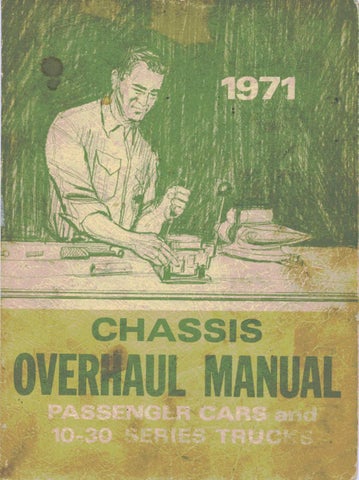
15. Install the selected shim between the service spacer and bearing, using a soft-face ham m er (fig. 24). 16. Install right bearing cap and torque both bearing caps to specifications. M ount a dial indicator on the carrier and check backlash between ring gear and pinion (fig. 25A). Backlash should be within the range of .003" to .010" with a reading of .005" to .008" preferred. Check reading at four equally spaced positions around the ring gear. Variation in reading should not exceed .002".
NOTE: Position the dial indicator so that indicator button is perpendicular to tooth angle and in line with gear rotation.
If variation in backlash exceeds .002" measure ring gear and case runout as shown in Figure 26A. Gear runout should not exceed .002"; should runout exceed this limit, check ring
Fig. 2 3 A -M e a su rin g Gauge Plate Thickness Fig. 2 4 A -ln s ta llin g D ifferential Shim