3 minute read
Rear C ylinder Half 53. Rear Head-to-Shell


bearing preload. Service, steel, adjusting shims are available in thicknesses ranging from .040" to .100" in increments of
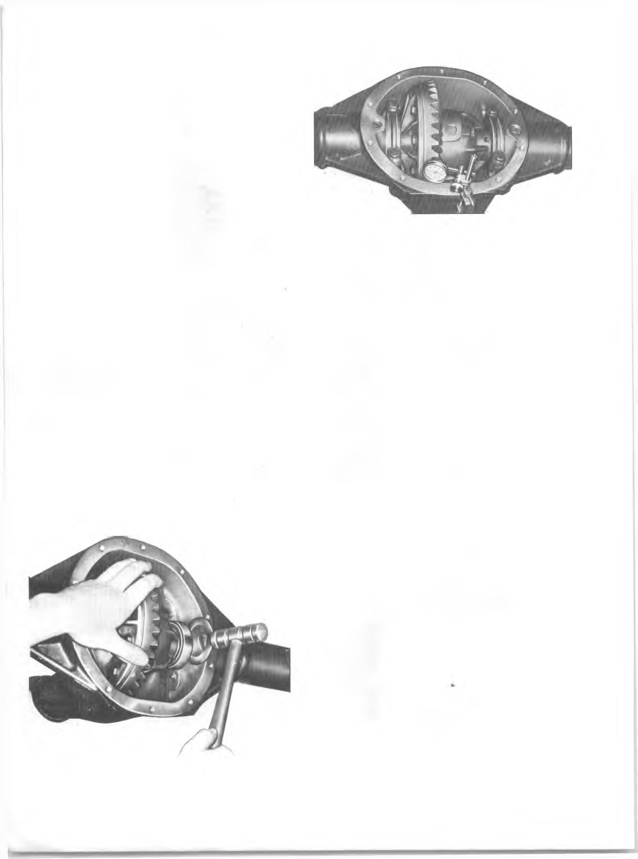
.002". 1. Before installation of case assembly, make sure that side bearing surfaces in carrier are clean and free of burrs. Side bearings must be oiled with gear lube and if same bearings are being reused, they must have original outer races in place. 2. Place differential case and bearing assembly in position in carrier. Use service type adjusting shim totaling same thickness as original production type adjusting shims if either new or reused bearings are to be used. Slip left shims in position at left bearing with steel shim next to bearing, then place .170" shim for right side in position and drive steel shim carefully into position between bearing and cast shim using a soft hammer. See Figure 18B. Install side bearing caps, as previously m arked and tighten bolts to 55 lb. ft. before checking side bearing preload or backlash. 3. Rotate differential case assembly several complete turns to seat bearings. Check bearing preload using an inch pound torque wrench connected at pinion nut. Bearing preload should read 35-40 lb. in. of rotating torque with new bearings or 20-25 lb. in. of rotating torque with reused bearings. See Figure 14B. If preload is not according to these specifications, increase shim thickness on each side .002" for each additional 10 lb. in. preload desired, or decrease shim thickness .002" on each side for each 10 lb. in. preload to be subtracted.
A d ju s t D iffe re n tia l B a c k la s h
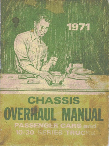
1. Rotate differential case several times to seat bearings, then m ount dial indicator as shown in Figure 19B. Use a small button on indicator stem so that contact can be made near heel end of tooth. Set dial indicator so that stem is as nearly as possible in line with gear rotation and perpendicular to tooth angle for accurate backlash reading.
Fig. 1 8B—Installing D ifferential Shim Fig. 19B~Checking Ring Gear Backlash
2. W ith pinion locked to carrier, check gear lash at 3 or 4 points around ring gear. Lash m ust not vary over .001" around ring gear. If variation is over .001" check for burrs, uneven bolting conditions or distorted case flange and make corrections as necessary. 3. G ear lash at the point of minimum lash should be .006" to .008" for all new gears. If adjustm ent is necessary, adjust to .007". If original gear set having a wear pattern is being reinstalled, original gear lash should be m aintained within plus or minus .001". 4. If gear backlash is not within specifications, correct by increasing thickness of one differential shim and decreasing thickness of other shim the same amount. In this way, correct differential bearing preload will be maintained. Shift .002" in shim thickness for each .001" change in backlash desired. If backlash is .002" too much, decrease thickness of right shim .004" and increase thickness of left shim .004". If backlash is .002" too little, increase thickness of right shim .004" and decrease thickness of left shim .004". 5. Install axle shaft assemblies as outlined in the Chassis
Service Manual.
G ear Tooth C o n ta c t Pattern C h e c k
G ear Tooth N om enclature
The side of the ring gear tooth which curves outward, or is convex, is referred to as the "drive" side. The concave side is the "coast" side. The end of the tooth nearest center of ring gear is referred to as the "toe" end.
The end of the tooth farthest away from center is the "heel" end. Toe end of tooth is smaller than heel end. It is very im portant that tooth contact be tested before the differential carrier assembly is disassembled. Variations in the carrier or pinion rear bearing may cause the pinion to be too far away from, or close to, the ring gear. Thus, the tooth contact m ust be tested and corrected if necessary, or the gears may be noisy.
T e st
1. Wipe oil out of carrier and carefully clean each tooth of ring gear.