1 minute read
Axle Shaft


J
Fig. 9 A -D rive Pinion Front Bearing Cup Installation
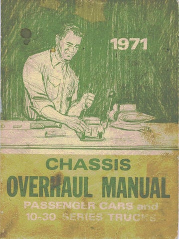
tow ard shoulder in carrier, then using Cup Installer J-7137 for heavy-duty axle and J-7817 for light-duty axle to install front cup and J-0270- 14 for light-duty axle and J-8608 for heavy-duty axle to install rear cup, press cup into carrier until it seats against shoulder (figs. 8A and 9A). Check installation to make certain that cup is not cocked and that it is fully seated against shoulder.
3. Remove pinion rear bearing cone and roller assembly, using Press Plate Tool J-22912 (fig. 10A). Record thickness of shim removed from between bearing cone and pinion head. 4. If the original ring gear and pinion and the pinion rear bearing assembly are to be reinstalled, the original shim or one of the same thickness may be used. If the ring gear and pinion or the pinion rear bearing assembly are replaced, the correct shim thickness may be determined as follows. 5. Lubricate pinion bearing cone and roller assemblies and position them in proper cups.
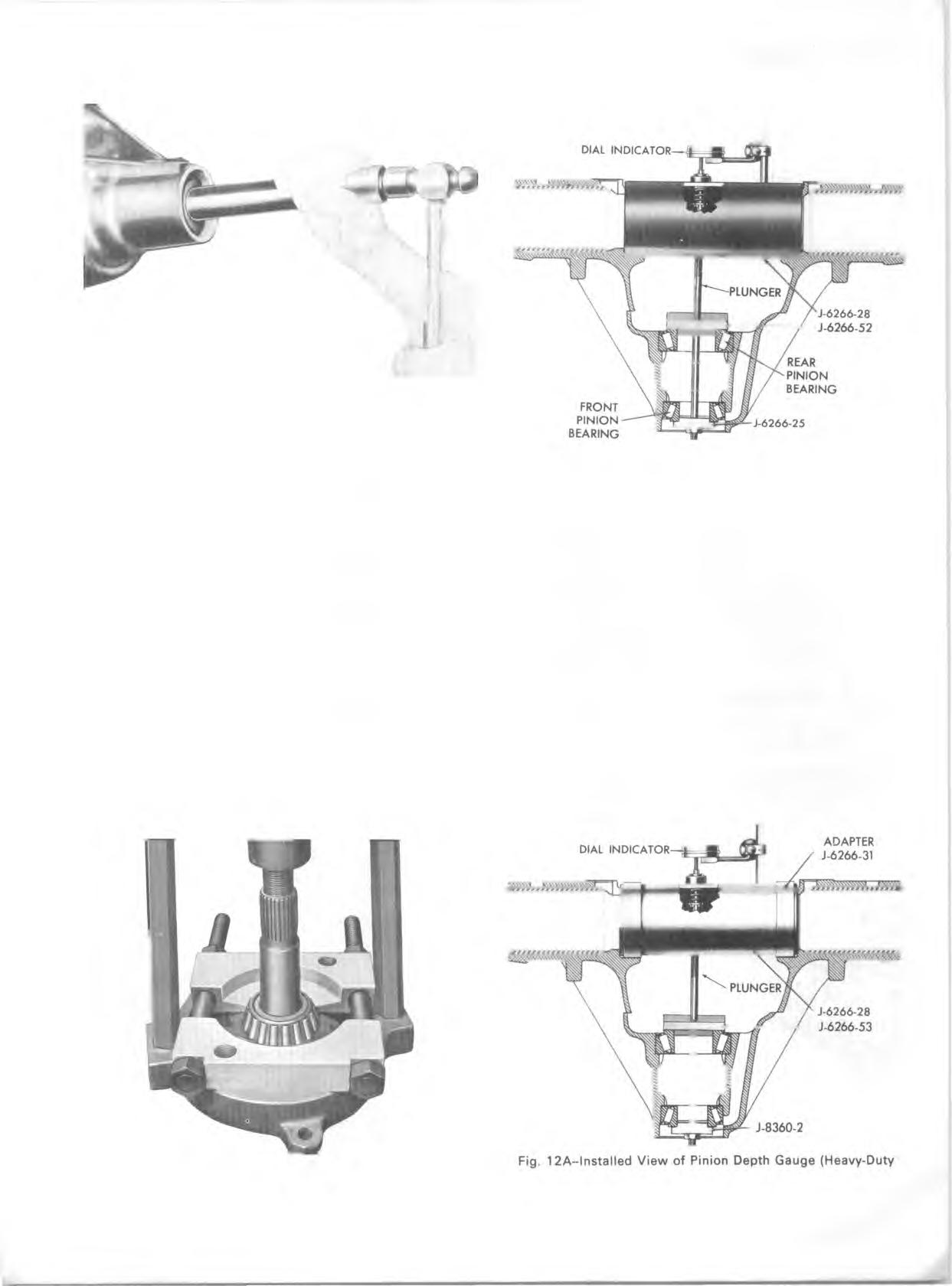
Fig. 1 1 A -ln sta lle d V ie w of Pinion Depth Gauge (Light-Duty Axle)
6. For Passenger Cars: Light-D uty Axles--J-6266-52- -position gauge plate with lower surface (x stamped near low side) tow ard top of carrier (fig. 11 A). Heavy-Duty Axles--J-6266-53-position gauge plate with higher surface (x stamped near high side) toward top of carrier (fig. 12A). a. Insert clamp screw through gauge plate and both of the pinion bearings. b. Position J-6266-25 (light-duty axle) or J-8360-2 (heavy-duty axle) on threaded end of clamp screw and index it in front bearing. Install hex nut and rotate bearings several times to make sure that they are seated. 7. For Truck: Position J-6266-52 Pinion Depth Setting
Gauge Plate in pinion rear bearing (fig. 13A). Gauge plate has two gauging surfaces.
Fig. 10 A -D rive Pinion Cone and Roller Assem bly Removal Axle)