
30 minute read
Lower Control Arm Pivot Bars to Frame Crossmember Bolts

from 1956 Chrysler C-71 (Windsor) C-72 (New Yorker) C-300B(Chrysler) C-73(Custom Imperial) Service Manual

c. Cleaning and Inspection
Thoroughly wash all metal parts in Bendix Metaclene (or recommended MOPAR Cleaner), and wash rubber parts in alcohol. Use air hose to blow out dirt and cleaner fluid from recesses and internal passages. Place washed parts on clean paper or lintless cloth. When overhauling power unit, use all parts in repair kit. Discard matching parts from original unit. Inspect all other parts and replace damaged or excessively worn parts. If inside of vacuum cylinder is rusted or corroded, polish with steel wool or fine emery cloth. If inspection reveals nicks or scratches on piston rod, valve seat at end of valve rod, or valve seat at center of piston plate, replace parts. If piston leather packing or piston rod leather seal are worn excessively, replace.
d. Assembly
Assemble piston plate with threaded hole side up (Fig. 26). Assemble leather packing on piston with lip side up. Place packing retainer plate on packing, with raised side up, and align holes in piston. Coil cotton wick inside of packing lip and cut wick to required length. Remove and dip wick in Bendix Vacuum Cylinder Oil. Let excess oil drip off, and again coil wicking inside of lip of packing. Install expander spring inside of wicking, with gripper points next to wicking. Engage notch at loop end of spring with hook at opposite end of spring. Align holes in expander spring retainer plate with threaded holes in piston plate. Install six screws and tighten securely. Assemble vacuum inspection port screw and screw gasket to mounting ring, if screw was removed (Fig. 27.)
Insert four bolts and lockwashers through holes in end plate and assemble mounting ring rubber gasket over bolts.
Fig. 26—Assembly of Piston Packing and Retainer
1—Screw 2—Expander spring retainer plate 3—Expander spring 4—Cotton wick 5—Piston plate 6—Leather packing 6 7
56x97
Fig. 27—Assembly of Mounting Ring, Gasket and Piston Rod Seal to End Plate
1-Screw (4) 2—End plate 3—Rubber gasket 4—Piston rod leather seal 5—Seal retainer 6—Retaining spring 7—Mounting spring 8-Gasket 9—Inspection port screw
NOTE Align gasket inspection hole with holes in mounting ring and end plate.
Assemble new piston rod leather seal on gasket, with lip side away from gasket, and center seal over hole in gasket. Place seal retainer over seal and install retaining spring. Coat bearing surface of mounting ring with silicone grease and assemble mounting ring on end plate, making certain inspection port hole in mounting ring lines up with hole in gasket. Thread four bolt into mounting ring and securely fasten bolts. When bolts are tight, outer rim of mounting ring should be in contact with end plate.
Slide rubber stop washer over piston rod up against steel washer on piston rod, and insert rod through seal in end plate (Fig. 28). Assemble piston return spring on end plate, with large diameter end next to end plate. Align slot in piston rod with vacuum test port in end plate. Align piston so that two of four threaded holes in valve side of piston are in line with slot in piston rod. Press piston on piston rod up against shoulder of rod and install retaining pin. Insert valve rod in piston until end of rod protrudes at opposite end of plate. (Fig. 29). Assemble friction collar, valve rod spring, and spring retainer washer over valve rod. Compress spring and install snap ring in groove of valve rod. Install valve rod seal over end of valve rod and piston rod.
NOTE To aid in seal installation, turn seal partially inside out. Assemble small diameter end of seal
PISTON ROD PIN VACUUM TEST PORT
PISTON ROD SLOT
SHORTER LENGTH ACROSS END PLATE FLANGE MUST BE ON VERTICAL CENTER LINE
56x98A
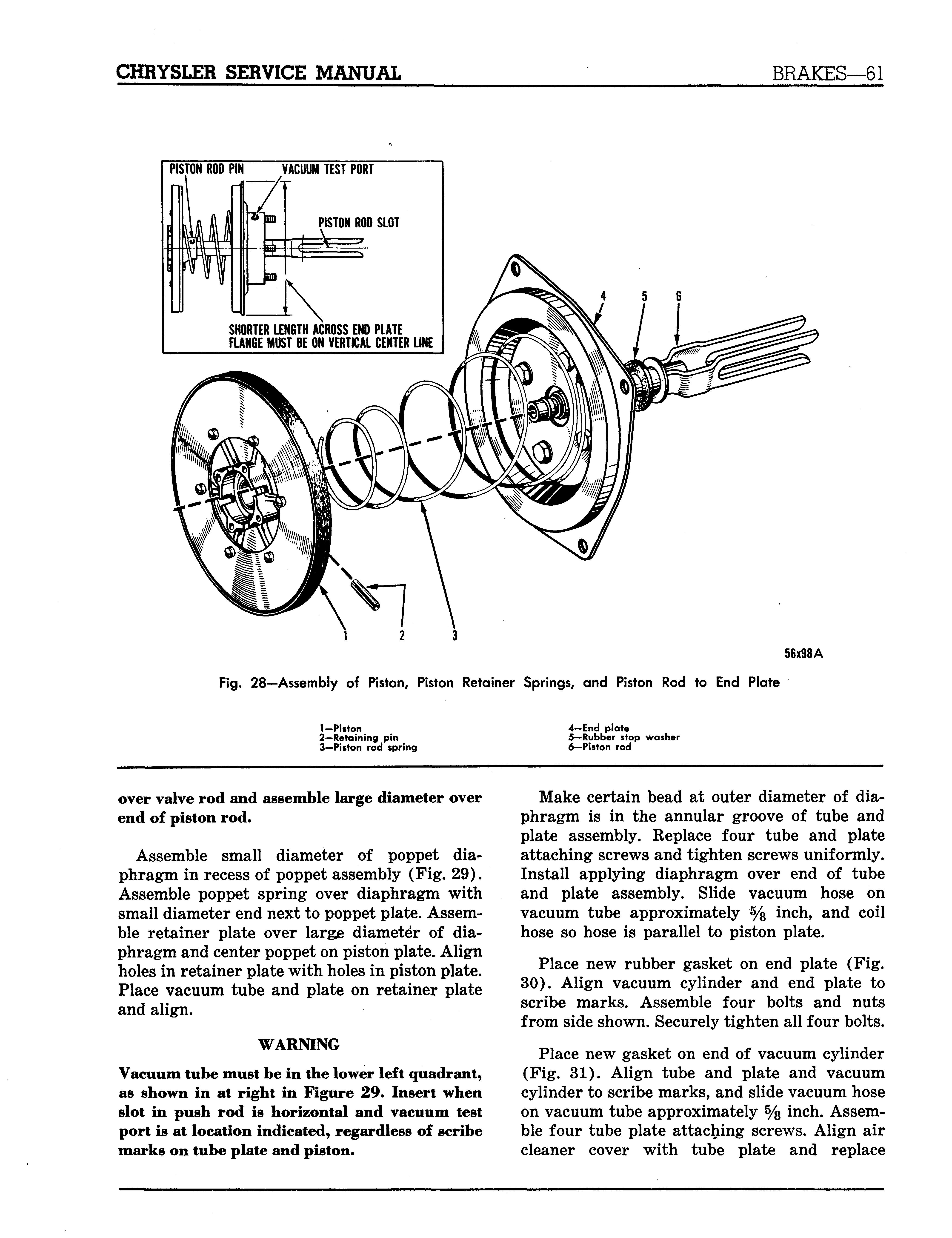
F i g. 2 8 — A s s e m b ly of Piston, Piston R e t a i n er S p r i n g s, a nd Piston R od to E nd P l a te
1-Piston 2—Retaining pin 3-Piston rod spring 4-End plate 5—Rubber stop washer 6—Piston rod
over valve rod and assemble large diameter over end of piston rod.
Assemble small diameter of poppet diaphragm in recess of poppet assembly (Fig. 29). Assemble poppet spring over diaphragm with small diameter end next to poppet plate. Assemble retainer plate over large diameter of diaphragm and center poppet on piston plate. Align holes in retainer plate with holes in piston plate. Place vacuum tube and plate on retainer plate and align.
WARNING Vacuum tube must be in the lower left quadrant, as shown in at right in Figure 29. Insert when slot in push rod is horizontal and vacuum test port is at location indicated, regardless of scribe marks on tube plate and piston.
Make certain bead at outer diameter of diaphragm is in the annular groove of tube and plate assembly. Replace four tube and plate attaching screws and tighten screws uniformly. Install applying diaphragm over end of tube and plate assembly. Slide vacuum hose on vacuum tube approximately % inch, and coil hose so hose is parallel to piston plate.
Place new rubber gasket on end plate (Fig. 30). Align vacuum cylinder and end plate to scribe marks. Assemble four bolts and nuts from side shown. Securely tighten all four bolts.
Place new gasket on end of vacuum cylinder (Fig. 31). Align tube and plate and vacuum cylinder to scribe marks, and slide vacuum hose on vacuum tube approximately % inch. Assemble four tube plate attaching screws. Align air cleaner cover with tube plate and replace
1 2 3 4 5 6 7 LOCATION OF VACUUM TEST PORT 22'/2
TION OF VACUUM TUBE AND HOSE
12 13 14 15 16
10 1
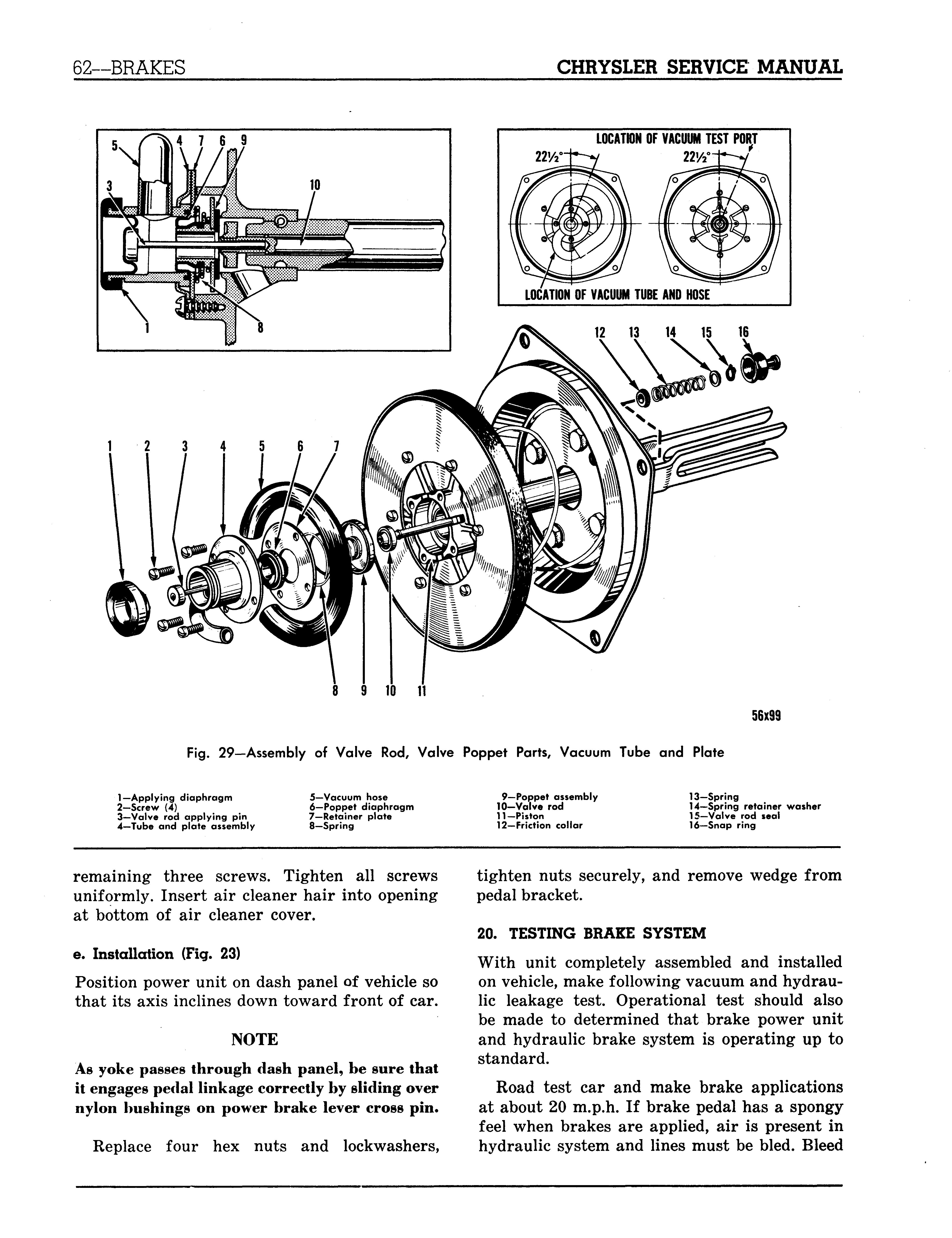
Fig. 29—Assembly of V a l ve Rod, V a l ve Poppet Parts, V a c u um Tube a nd Plate
56x99
1—Applying diaphragm 2-Screw (4) 3—Valve rod applying pin 4—Tube and plate assembly 5—Vacuum hose 6—Poppet diaphragm 7—Retainer plate 8—Spring 9—Poppet assembly 10-Valve rod 11-Piston 12—Friction collar 13-Spring 14—Spring retainer washer 15-Valve rod seal 16—Snap ring
remaining three screws. Tighten all screws uniformly. Insert air cleaner hair into opening at bottom of air cleaner cover.
e. Installation (Fig. 23) Position power unit on dash panel of vehicle so that its axis inclines down toward front of car.
NOTE As yoke passes through dash panel, be sure that it engages pedal linkage correctly by sliding over nylon bushings on power brake lever cross pin.
Replace four hex nuts and lockwashers, tighten nuts securely, and remove wedge from pedal bracket.
20. TESTING BRAKE SYSTEM With unit completely assembled and installed on vehicle, make following vacuum and hydraulic leakage test. Operational test should also be made to determined that brake power unit and hydraulic brake system is operating up to standard.
Road test car and make brake applications at about 20 m.p.h. If brake pedal has a spongy feel when brakes are applied, air is present in hydraulic system and lines must be bled. Bleed
56x100
Fig. 30—Assembly of Vacuum Cylinder to Piston End Plate Assembly
1-Cylinder bolt (4)2—Vacuum cylinder
3-Gasket 4-End plate
brake system at each wheel cylinder.
With engine not running, apply brakes several times to exhaust all vacuum in system. Depress brake pedal, hold foot pressure on pedal, and start engine. As soon as engine begins to operate, brake pedal will tend to fall away under foot pressure, and less pressure will be required to hold pedal in applied position.
If there is NO noticeable difference in pedal effect with or without engine running, vacuum system is not functioning. Check for restriction in vacuum supply line, restriction on air cleaner, faulty pedal adjustments, or faulty power unit operation.
Stop engine and again exhaust all vacuum in system. Depress brake pedal and hold foot pressure on pedal. If pedal gradually falls away under foot pressure, hydraulic system is leaking. If brake pedal travels to within one inch of toe board, brake shoes require re-adjustment or relining.
Fig. 31—Assembly of Air Cleaner, Tube and Plate to Vacuum Cylinder
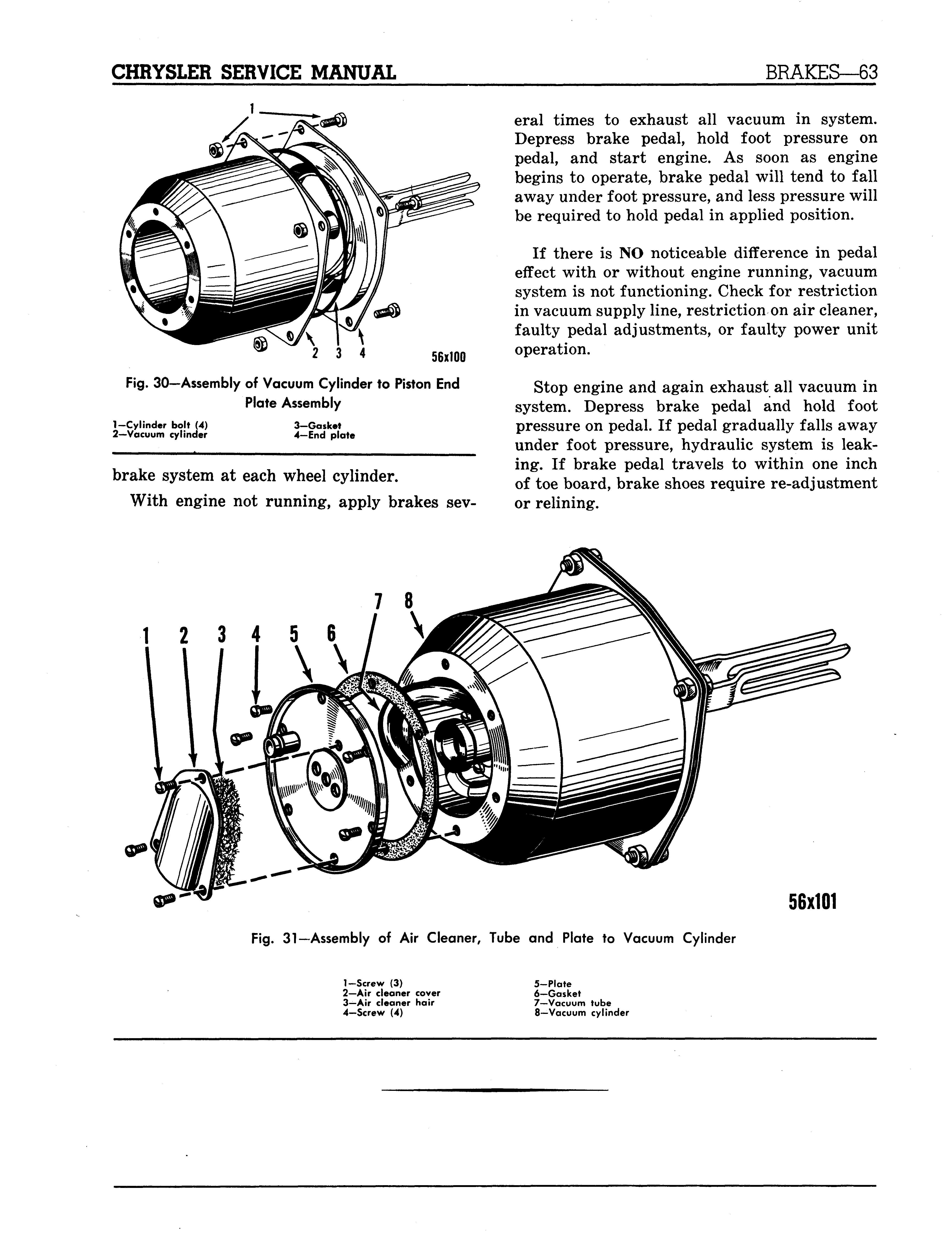
1-Screw (3) 2—Air cleaner cover 3-Air cleaner hair 4-Screw (4) 5-Plate 6—Gasket 7—Vacuum tube 8—Vacuum cylinder
56x101
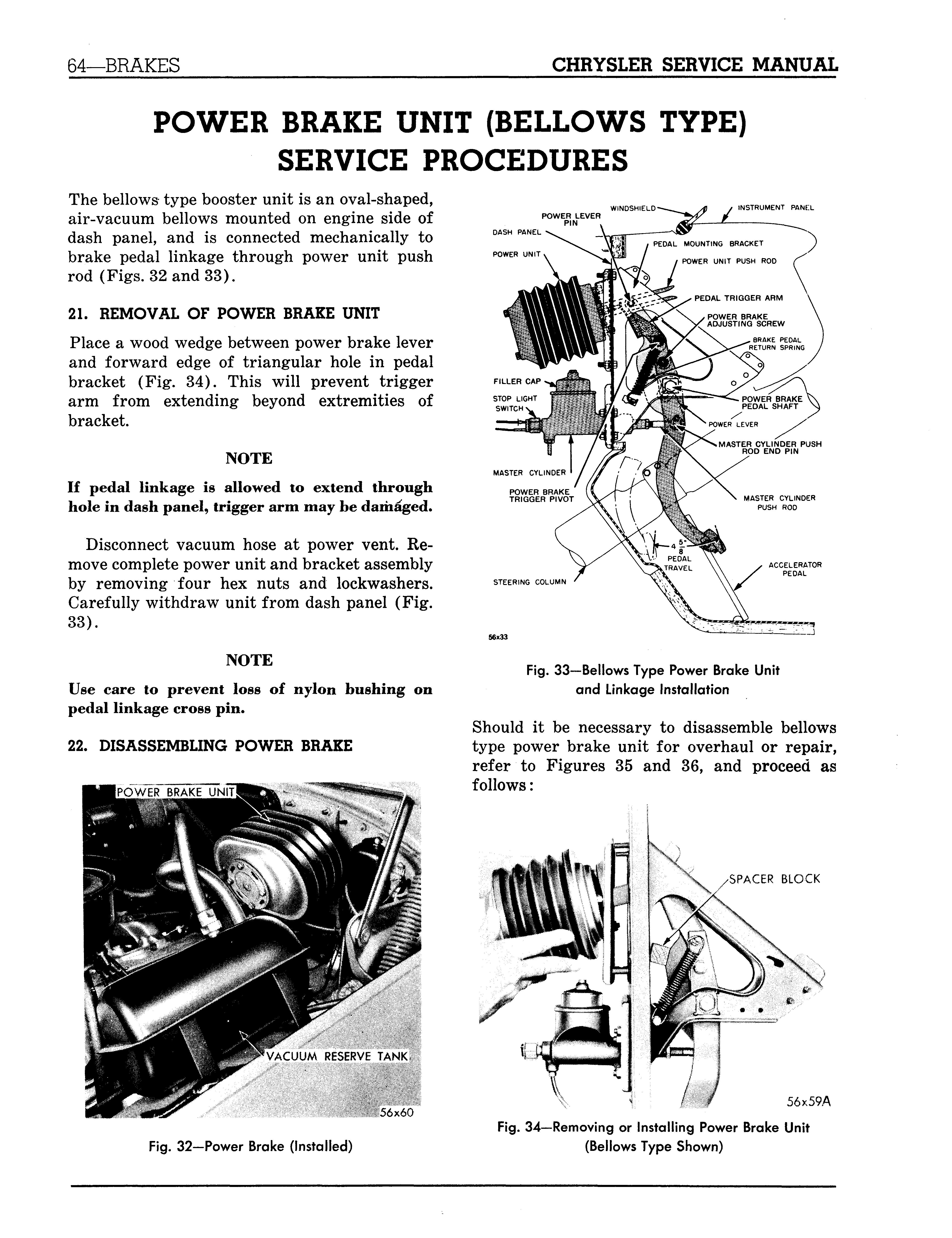
The bellows type booster unit is an oval-shaped, air-vacuum bellows mounted on engine side of dash panel, and is connected mechanically to brake pedal linkage through power unit push rod (Figs. 32 and 33).
21. REMOVAL OF POWER BRAKE UNIT Place a wood wedge between power brake lever and forward edge of triangular hole in pedal bracket (Fig. 34). This will prevent trigger arm from extending beyond extremities of bracket.
NOTE If pedal linkage is allowed to extend through hole in dash panel, trigger arm may be damaged.
Disconnect vacuum hose at power vent. Remove complete power unit and bracket assembly by removing four hex nuts and lockwashers. Carefully withdraw unit from dash panel (Fig. 33).
NOTE Use care to prevent loss of nylon bushing on pedal linkage cross pin.
22. DISASSEMBLING POWER BRAKE
POWER LEVER PIN
DASH PANEL
POWER UNIT, INSTRUMENT PANEL
STEERING COLUMN
Fig. 33—Bellows Type Power Brake Unit and Linkage Installation
Should it be necessary to disassemble bellows type power brake unit for overhaul or repair, refer to Figures 35 and 36, and proceed as follows:
SPACER BLOCK
VACUUM RESERVE TANK,
' •-•' ' 56x60
56x59A
Fig. 34—Removing or Installing Power Brake Unit (Bellows Type Shown)
T O V A C U U M SOURCE
AIR-VACUUM BELLOWS
AIR INLET.
AIR VALVE
AIR VALVE SPRING.
VACUUM VALVE
AIR FILTER
VACUUM VALVE SPRING VALVE OPERATING ROD
YOKE
Fig. 35—Bellows Type Power Brake (Sectional View) 56x29 56x29
Remove nuts that attach mounting plate to unit. Slide plate off and away from unit. Remove and discard mouning plate " 0" ring.
Using an Allen wrench, back out two set screws sufficiently to allow removal of yoke (Fig. 37). Slide yoke off end of guide and away from unit. (Slightly compress bellows by hand for clearance when loosening set screw.) Remove rubber stop seal washer. Lift valve oper-

YOKE
SET SCREWS ating rod out of unit, remove, and discard valve operating rod button seal (Fig. 38).
Remove nuts that attach outer mounting plate. Using screwdriver, pry up gently on plate to loosen. Lift plate straight up and away from
NYLON BUTTON
STOP-SEAL WASHER
OUTER MOUNTING PLATE
NOTCH
GUIDE
x528 NOTCH BELLOWS
VALVE COVER PLATE—"—™* 56x529 Fig. 38—Removing or Installing Operating Rod

.2 1
JQ
COMPRESS BELLOWS , SLIGHTLY GUIDE
INNER MOUNTING PLATE GUIDE BELLOWS SUPPORTS (3)
56x531
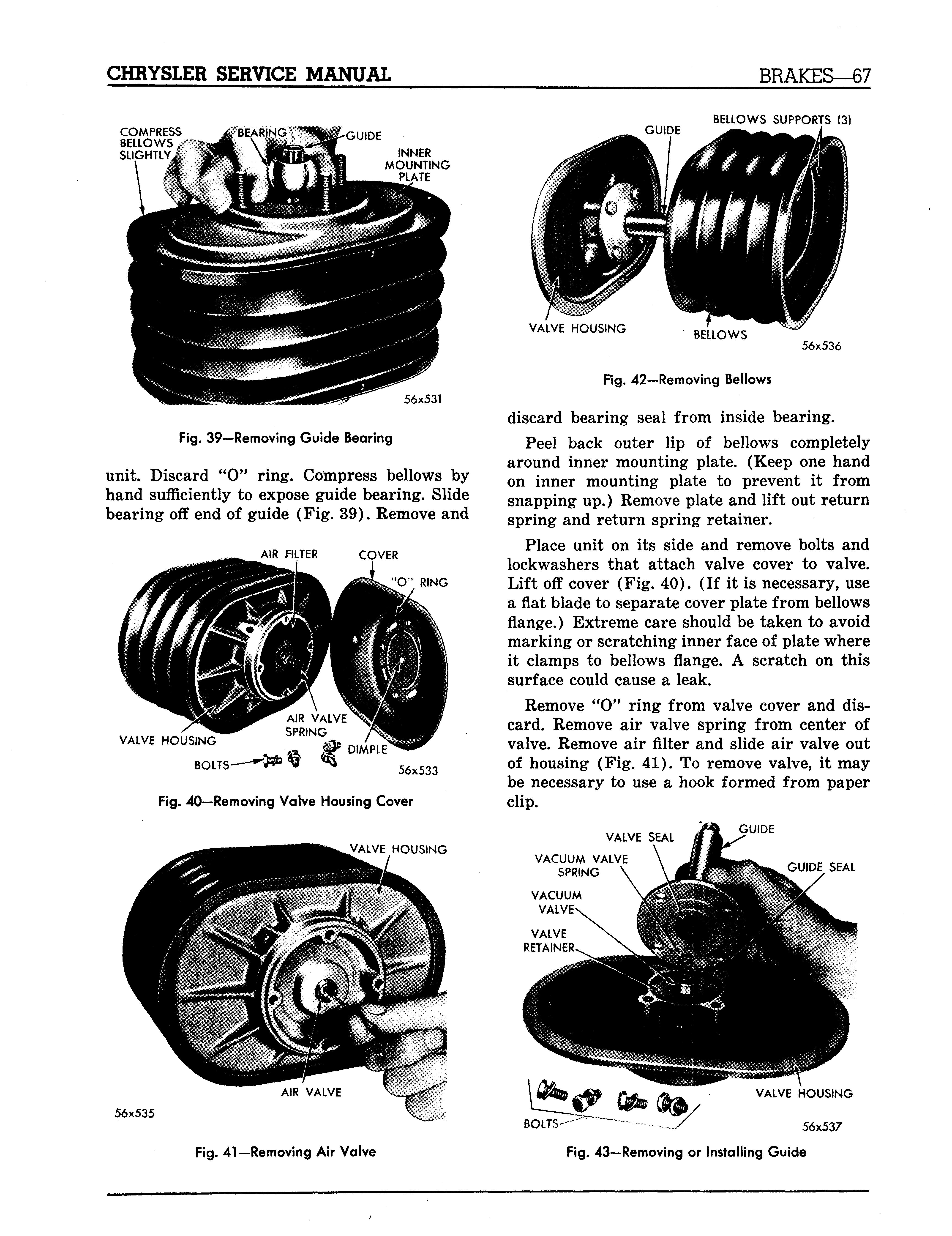
Fig. 39—Removing Guide Bearing
unit. Discard " 0" ring. Compress bellows by hand sufficiently to expose guide bearing. Slide bearing off end of guide (Fig. 39). Remove and
AIR fILTER
VALVE HOUSING
BOLTS 56x533
Fig. 40—Removing Valve Housing Cover
VALVE HOUSING VALVE HOUSING BELLOWS
56x536
Fig. 42—Removing Bellows
discard bearing seal from inside bearing.
Peel back outer lip of bellows completely around inner mounting plate. (Keep one hand on inner mounting plate to prevent it from snapping up.) Remove plate and lift out return spring and return spring retainer.
Place unit on its side and remove bolts and lockwashers that attach valve cover to valve. Lift off cover (Fig. 40). (If it is necessary, use a flat blade to separate cover plate from bellows flange.) Extreme care should be taken to avoid marking or scratching inner face of plate where it clamps to bellows flange. A scratch on this surface could cause a leak.
Remove " 0" ring from valve cover and discard. Remove air valve spring from center of valve. Remove air filter and slide air valve out of housing (Fig. 41). To remove valve, it may be necessary to use a hook formed from paper clip.
VALVE SEAL
VACUUM VALVE SPRING
VACUUM VALVE GUIDE
GUIDE SEAL
VALVE RETAINER
56x535
\ VALVE HOUSING
BOLTS--" 56x537
VACUUM VALVE
VACUUM VALVE RETAINER VACUUM VALVE AND RETAINER
VALVE HOUSING
Fig. 44—Removing the Vacuum and Retainer
Place valve housing end down on bench. Remove bellows from valve by peeling back outer lip of bellows (Fig. 42). Lift bellows up and away from valve. If new bellows is to be installed, remove 3 bellows support.
Remove bolts and lockwashers that attach guide to valve body. Lift off guide to expose vacuum valve, valve spring and seals (Fig. 43). Remove seals and discard them.
Lift out vacuum valve and retainer (Fig. 44). Remove and discard valve housing to guide seal. Invert valve housing and remove air valve seal from its groove in valve body (Fig. 45). CAUTION Work carefully to avoid marking or scratching inside diameter bore of valve housing.
The bellows type power brake now has been disassembled as much as necessary for cleaning and inspection. Clean all parts (except bellows, bearing and air filter) in solvent and blow dry with compressed air. Place cleaner parts on clean paper for reassembly. If necessary, bellows may be washed with water and mild soap.

AIR VALVE SEAL (LIPS OF SEAL FACING OUT VALVE HOUSING
56x541
Fig. 46—Installing the Vacuum Valve and Retainer
Inspect all parts for wear or damage and check air valve for signs of scoring or wear. If valve body or valve is scored or worn, install new parts as required. Always use new "O" and seal rings.
23. ASSEMBLING THE POWER BRAKE
Be sure all seals and " 0" rings are suitably coated with silicone grease (rings and seals precoated in Parts Kits). Refer to Figure 45, and assemble as follows:
Insert new air valve seal into bore of valve housing (lips of seal facing out when installed). (Refer to Fig. 46). Carefully position new vacuum valve in retainer. Invert valve housing and install vacuum valve and retainer in housing. Press down firmly on retainer to snap it in place.
Position new valve housing to guide seal in groove provided. Install new vacuum valve seal in bore of guide, with lips of seal toward bottom of bore (Fig. 47).
Install vacuum valve spring in center of valve. Position guide over vacuum valve, lining
SEAL (LIPS TOWARD BORE)
VALVE
H O U S I N G 56x539 GUIDE
56x54?
COVER NOTCH
FOLD UP OVER VALVE BODY HOLDING FIXTURE
56x543
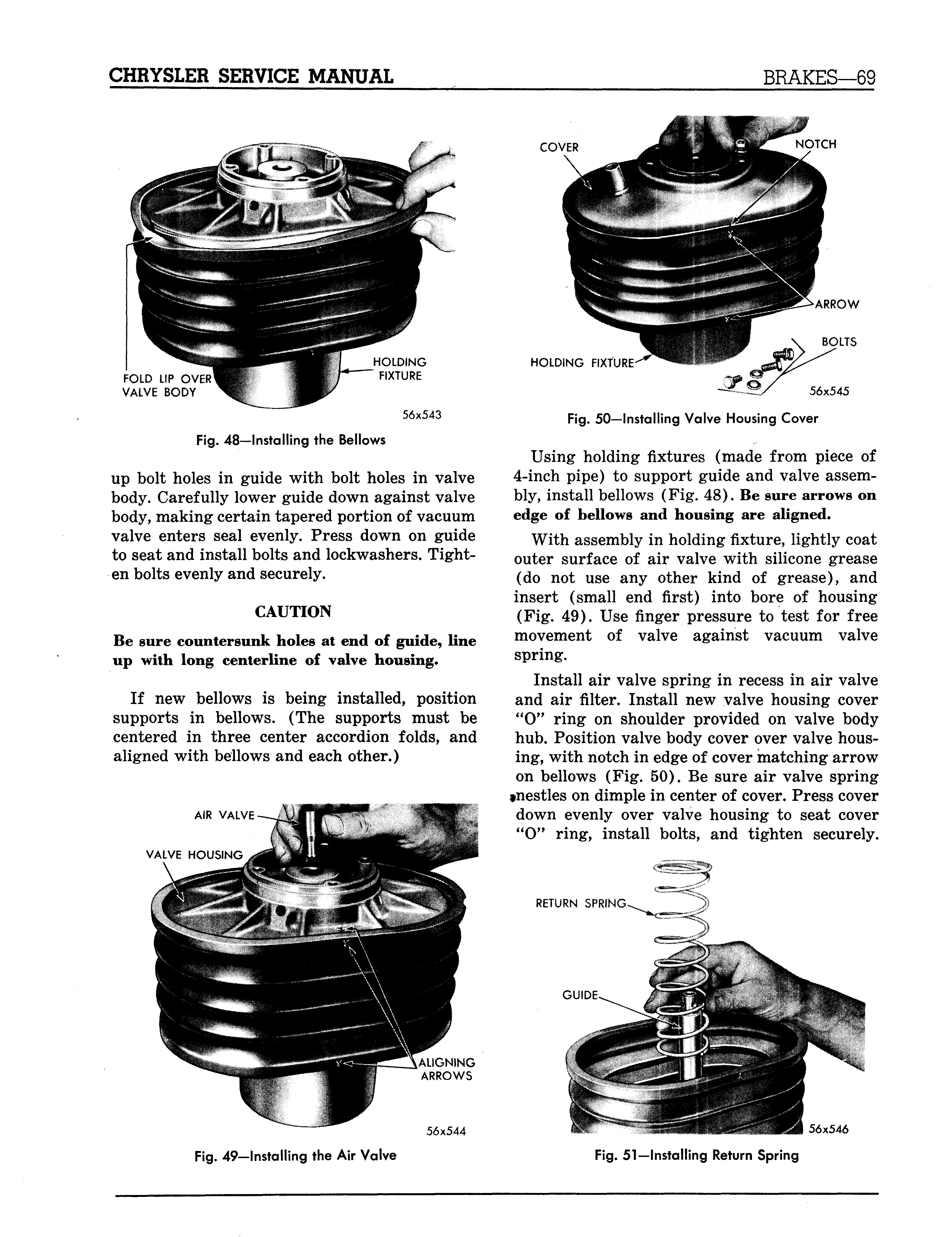
Fig. 48—Installing the Bellows
up bolt holes in guide with bolt holes in valve body. Carefully lower guide down against valve body, making certain tapered portion of vacuum valve enters seal evenly. Press down on guide to seat and install bolts and lockwashers. Tighten bolts evenly and securely.
CAUTION Be sure countersunk holes at end of guide, line up with long centerline of valve housing.
If new bellows is being installed, position supports in bellows. (The supports must be centered in three center accordion folds, and aligned with bellows and each other.)
AIR VALVE ARROW
HOLDING FIXTURE' BOLTS
56x545
Fig. 50—Installing Valve Housing Cover
Using holding fixtures (made from piece of 4-inch pipe) to support guide and valve assembly, install bellows (Fig. 48). Be sure arrows on edge of bellows and housing are aligned.
With assembly in holding fixture, lightly coat outer surface of air valve with silicone grease (do not use any other kind of grease), and insert (small end first) into bore of housing (Fig. 49). Use finger pressure to test for free movement of valve against vacuum valve spring.
Install air valve spring in recess in air valve and air filter. Install new valve housing cover " 0" ring on shoulder provided on valve body hub. Position valve body cover over valve housing, with notch in edge of cover matching arrow on bellows (Fig. 50). Be sure air valve spring »nestles on dimple in center of cover. Press cover down evenly over valve housing to seat cover " 0" ring, install bolts, and tighten securely.
RETURN SPRING
ALIGNING ARROWS
56x544
GUIDE
56x546
Remove assembly from holding fixture and invert unit. Coat guide lightly with silicone grease and install return spring. Position spring evenly around hub of valve housing and guide (Fig. 51).
Place spring retainer and inner mounting plate over spring, being sure arrow stamped on plate is in line with arrow on edge of bellows. Compress return spring and fold bellows lip over edge of plate. Be sure bellows fits evenly all around plate.
Install new guide bearing seal in groove inside bearing bore. The seal must nest snugly in bearing. Using silicone grease, lubricate inside of bearing and slide it over guide, while compressing bellows (Fig. 52). Bearing must be installed with lip of seal facing out. Push bearing down over guide and into pocket of plate. Release bellows and bearing will ride up guide with plate into position.
Install bearing to mounting plate " 0" ring and lower outer mounting plate down on assembly. The notch on edge of plate must be in line with arrow on bellows. Install nuts and draw down finger tight.
Slide new valve operating rod seal ring over nylon bumper on end of rod and into groove. Install rod in center of guide. Press on end of rod to test for free operation or movement of air and vacuum valves. A "two step" movement should be felt when rod is depressed and released fully.
Place new stop-seal washer in position and install yoke on end of guide. Compress bellows slightly and alternately tighten set screws. The hub of yoke must be down snug against shoulder of guide, with set screws aligned with tapered holes in guide. Tighten mounting plate nuts securely.
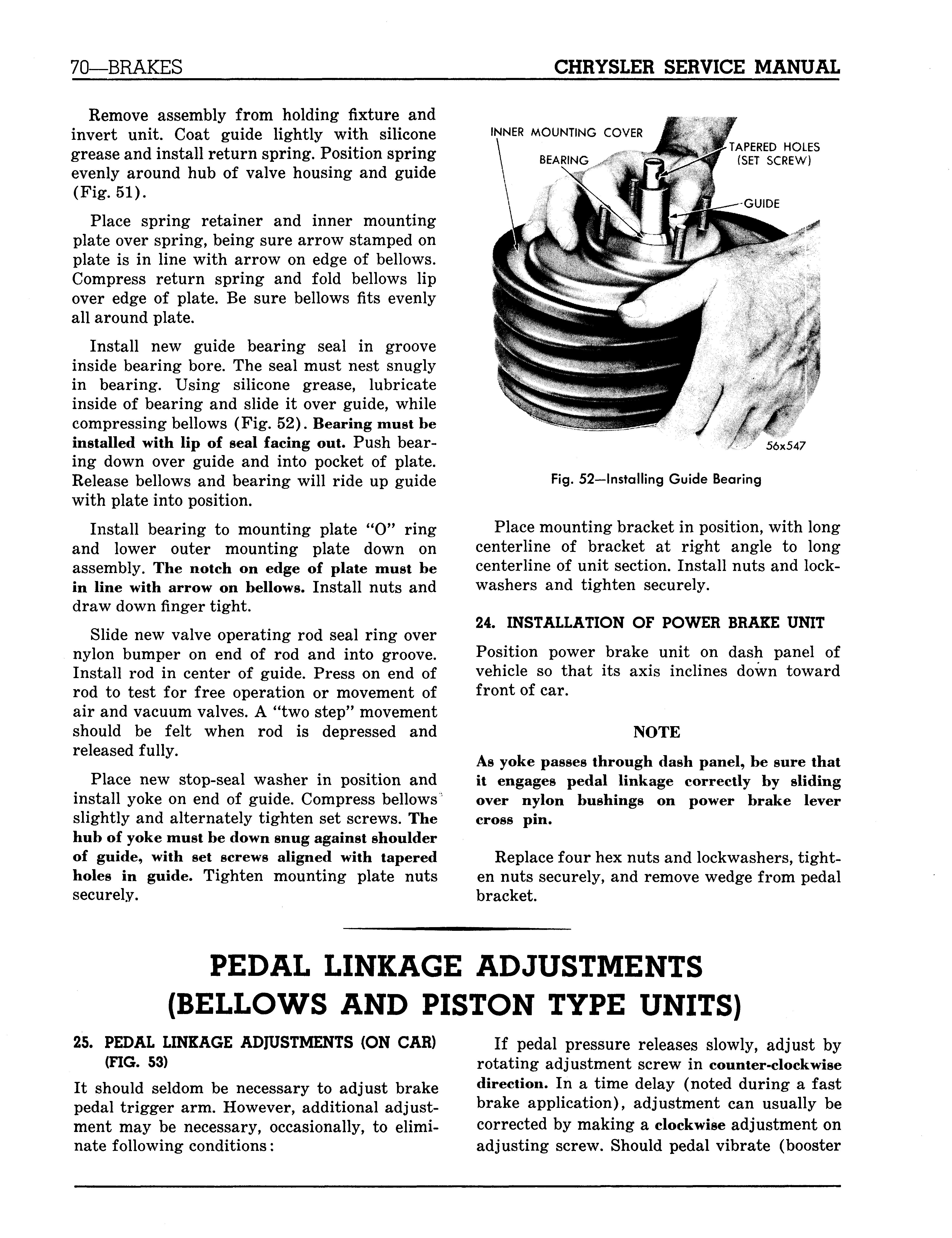
INNER MOUNTING COVER
TAPERED HOLES (SET SCREW)
56x547
Fig. 52—Installing Guide Bearing
Place mounting bracket in position, with long centerline of bracket at right angle to long centerline of unit section. Install nuts and lockwashers and tighten securely.
24. INSTALLATION OF POWER BRAKE UNIT Position power brake unit on dash panel of vehicle so that its axis inclines down toward front of car.
NOTE As yoke passes through dash panel, be sure that it engages pedal linkage correctly by sliding over nylon bushings on power brake lever cross pin.
Replace four hex nuts and lockwashers, tighten nuts securely, and remove wedge from pedal bracket.
PEDAL LINKAGE ADJUSTMENTS (BELLOWS AND PISTON TYPE UNITS)
25. PEDAL LINKAGE ADIUSTMENTS (ON CAR) (FIG. 53) It should seldom be necessary to adjust brake pedal trigger arm. However, additional adjustment may be necessary, occasionally, to eliminate following conditions:
If pedal pressure releases slowly, adjust by rotating adjustment screw in counter-clockwise direction. In a time delay (noted during a fast brake application), adjustment can usually be corrected by making a clockwise adjustment on adjusting screw. Should pedal vibrate (booster
56X89
Fig. 53—Checking Pedal Free Play (Bellows Type, Typical of Piston Type)

chatter), turn adjusting screw in counterclockwise direction (Fig. 53).
NOTE Rotation of adjustment screw should be limited to plus or minus 90 degrees about original setting.
26. ASSEMBLY OF PEDAL LINKAGE IN
PEDAL BRACKET
CAUTION Use extreme care during assembly or handling of linkage as power brake pedal trigger arm is easily damaged.
After reinstalling brake pedal linkage in pedal bracket,* a wooden wedge should be placed between power brake lever and forward edge of triangular hole in pedal bracket (if power unit has been removed). This will prevent trigger arm from extending beyond extremities of bracket. 27. LUBRICATION Except for an occasional few drops of SAE 10-W Engine Oil on power brake lever pin bushings, brake pedal linkage requires no further lubrication. The power unit will require no lubrication under normal usage.
28. PEDAL FREE PLAY ADJUSTMENT After master cylinder, booster, and pedal linkage are completely installed (and wooden wedge removed), a free play adjustment check should be made at no vacuum as follows:
NOTE Removing vacuum hose and pressing brake pedal several times will aid in obtaining no vacuum condition.
Insert blade of screwdriver between rubber collar of power brake trigger pivot and rear side of elongated hole in power brake lever, forcing them apart.
NOTE If brake pedal and power brake lever are not wedged apart, a false free play setting (which includes booster valve travel) will be measured at pad end of pedal.
Check free play with linkage in this position by pushing lightly at pad end of brake pedal (Fig. 53). Pedal free play travel should be between yS2 and Vi inch. If pedal free play movement does not come within required limits, adjustment is made by lengthening or shortening push rod as required.
29. ALTERNATE METHOD OF MEASURING
PEDAL FREE PLAY Remove master cylinder push rod end pin. Using light finger pressure, move push rod forward until contact is made with master cylinder piston. Attempt to insert push rod end pin through power lever and push rod end hole. If push rod must be pulled back to allow passage of push rod end pin, free play is present.
If push rod must be pushed further into master cylinder to allow passage of push rod end pin, no free play is present and an adjustment must be made at push rod.
30. SERVICING THE MASTER CYLINDER
The master cylinder can be bled and push rod end assembled at proper length, as described in this section. However, the length from push rod end hole to master cylinder mounting face has changed because of difference in brake pedal linkage. The distance from push rod end hole to master cylinder face is 4.7 inches. The service procedures covering master cylinder are same as on standard master cylinder.
SERVICE DIAGNOSIS (STANDARD BRAKES)
31. PEDAL GOES TO FLOOR
a. Check fluid in master cylinder, refill with MOPAR Super brake fluid. b. Check wear on brake lining, adjust or replace as necessary. c. Check master cylinder for corrosion, repair or replace as necessary. d. Check wheel cylinders, replace swollen cups. e. Check loose connections or broken lines, repair or replace as necessary.
32. SPONGY PEDAL
a. Check brake fluid contamination, replace with MOPAR Super brake fluid. b. Check brake drums, replace excessively refaced or broken drums. c. Air in brake system, bleed brakes using air-less bleeder tank unit, Tool C-837.
33. BRAKES PULLING TO ONE SIDE
a. Check tires, inflate to proper specifications. b. Check brakes, adjust for proper clearance. c. Check drums for out-of-round, machine drums and replace with brake shoes to fit drum. d. Check brake shoes for twist, straighten, reline or grind to fit drum. e. Oil, grease or brake fluid on shoes, clean with alcohol. f. Check brake lining, replace with matched lining. g. Check front spring, repair or replace as necessary.

34. SQUEALING BRAKES
a. Check lining, replace with proper lining. b. Check brake drum, clean or reface as necessary.
c. Check brake shoes, straighten or replace as necessary. d. Check brake support plate, straighten or replace. e. Check brake shoe return spring, replace as necessary.
35. DRAGGING BRAKE
a. Check hand brake, that it is fully released. b. Check wheel cylinders, repair or replace as necessary. c. Check brake shoe return spring, replace worn and broken springs. d. Excessive brake adjustment, adjust to proper clearance. e. Brake pedal binding, loosen pedal cross shaft.
36. HARD PEDAL
a. Check brake shoe lining, replace with proper lining. b. Check by-pass port in master cylinder, repair or replace as necessary. c. Check push rod, make proper adjustments.
37. WHEEL LOCKS
a. Check brake lining, replace torn or loose lining. b. Check wheel bearings, adjust to proper clearance. c. Check wheel cylinders, repair or replace as necessary.
38. BRAKE PEDAL FAILS TO RETURN
a. Check pedal return spring, adjust or replace as necessary. b. Check master cylinder, tighten loose mounting bolts. c. Check brake pedal mounting bracket, adjust bracket and tighten bolts.
Section IV
CLUTCH
Page
Clutch Pedal Adjustment 74
Clutch Disassembly 77
Clutch Assembly 78
Service Diagnosis 81
DATA AND SPECIFICATIONS
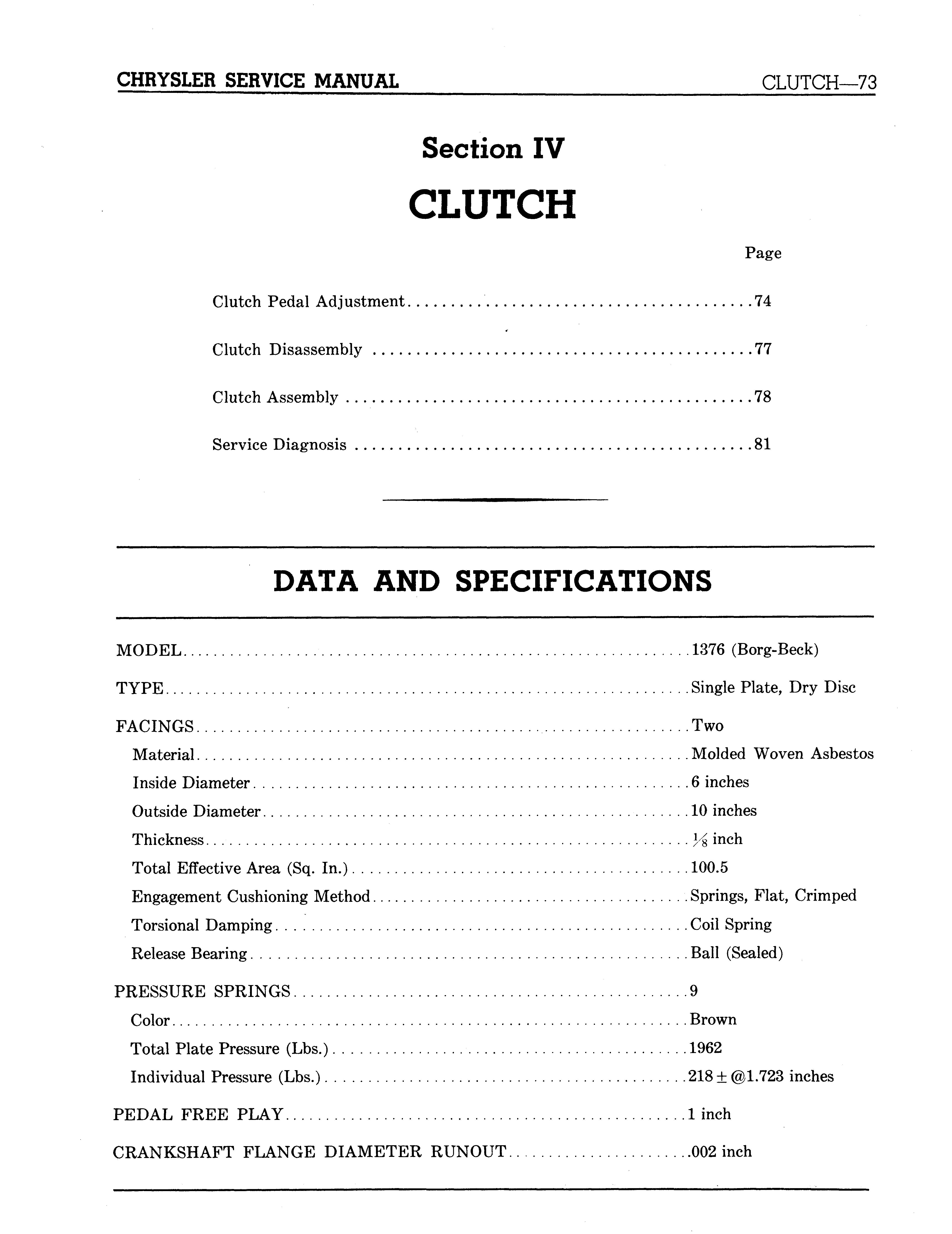
MODEL 1376 (Borg-Beck)
TYPE Single Plate, Dry Disc
FACINGS Two
Material Molded Woven Asbestos Inside Diameter 6 inches Outside Diameter 10 inches Thickness lA inch Total Effective Area (Sq. In.) 100.5 Engagement Cushioning Method Springs, Flat, Crimped Torsional Damping Coil Spring Release Bearing Ball (Sealed)
PRESSURE SPRINGS 9
Color Brown
Total Plate Pressure (Lbs.) 1962
Individual Pressure (Lbs.) 218 ± @1.723 inches
PEDAL FREE PLAY 1 inch
SPECIAL TOOLS
Tool Number Tool Name
C-3005. . . . : Wrench—100 Foot-Pound Sensory Type Torque C-3044 Wrench—Clutch Fork Pivot Lock Installing C-3181 Installer and Burnisher—Clutch Shaft Pilot Bushing C-3185 Remover—Clutch Shaft Pilot Bushing C-3309 Set—Dial Indicator C-360 Arbor—Clutch Shaft Aligning C-585-A (with Spacer No. 45) Fixture—Clutch Rebuilding and Adjusting C-647 Tester—Clutch Spring C-860 Reamer—Clutch Housing Oversize Dowel C-869 Bar—Clutch Housing Alignment Checking
TIGHTENING REFERENCES
Part Name

Rear Engine Support Bolts Clutch Cover Bolts Transmission to Clutch Housing Bolts Housing to Cylinder Block Bolts Flywheel Stud Nuts Foot-Pounds
85 20 50 50 60
Section IV CLUTCH
1. CLUTCH PEDAL ADJUSTMENT (FREE PLAY)
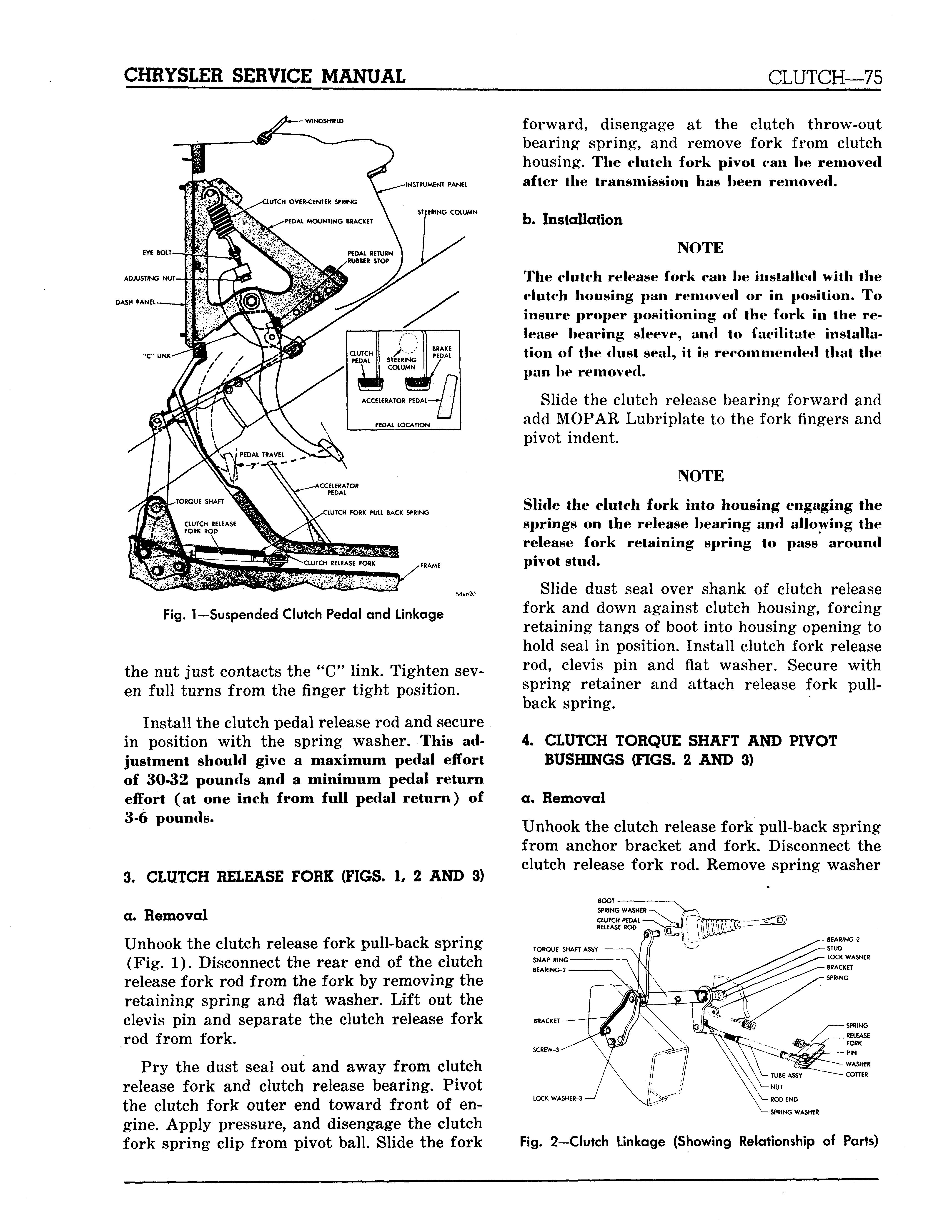
Clutch pedal free play is the movement of the clutch pedal before the clutch starts to engage or disengage. To compensate for normal clutch wear, adjust the clutch release fork rod, as shown in Figure 1, to obtain %G inch free play of the clutch release fork outer end. This will provide the one inch free pedal movement at the pedal, with a total of seven inch full pedal travel.
2. OVER-CENTER SPRING ADJUSTMENT
(FIGS. 1 AND 2)
Remove the spring washer that holds the clutch pedal release rod to the clutch pedal and back off the over-center spring adjusting nut until it is free of the "C" link.
With the clutch pedal depressed to the full seven inch travel, turn the adjusting nut until
STEERING COLUMN
Fig. 1—Suspended Clutch Pedal and Linkage
the nut just contacts the "C" link. Tighten seven full turns from the finger tight position.
Install the clutch pedal release rod and secure in position with the spring washer. This adjustment should give a maximum pedal effort of 30-32 pounds and a minimum pedal return effort (at one inch from full pedal return) of 3-6 pounds.
3. CLUTCH RELEASE FORK (FIGS. 1, 2 AND 3)
a. Removal
Unhook the clutch release fork pull-back spring (Fig. 1). Disconnect the rear end of the clutch release fork rod from the fork by removing the retaining spring and flat washer. Lift out the clevis pin and separate the clutch release fork rod from fork.
Pry the dust seal out and away from clutch release fork and clutch release bearing. Pivot the clutch fork outer end toward front of engine. Apply pressure, and disengage the clutch fork spring clip from pivot ball. Slide the fork
forward, disengage at the clutch throw-out bearing spring, and remove fork from clutch housing. The clutch fork pivot can he removed after the transmission has heen removed.
b. Installation
NOTE The clutch release fork can he installed with the clutch housing pan removed or in position. To insure proper positioning of the fork in the release hearing sleeve, and to facilitate installation of the dust seal, it is recommended that the pan he removed.
Slide the clutch release bearing forward and add MOPAR Lubriplate to the fork fingers and pivot indent.
NOTE Slide the clutch fork into housing engaging the springs on the release hearing and allowing the release fork retaining spring to pass around pivot stud.
Slide dust seal over shank of clutch release fork and down against clutch housing, forcing retaining tangs of boot into housing opening to hold seal in position. Install clutch fork release rod, clevis pin and flat washer. Secure with spring retainer and attach release fork pullback spring.
4. CLUTCH TORQUE SHAFT AND PIVOT
BUSHINGS (FIGS. 2 AND 3)
a. Removal
Unhook the clutch release fork pull-back spring from anchor bracket and fork. Disconnect the clutch release fork rod. Remove spring washer
TOROUE SHAFT ASSY SNAP RING BEARING-2
LOCK WASHER-3 WASHER COTTER
BEARING REINFORCEMENT
BRACKET
WASHER
LOCKWASHER
I NUT
PAO-
Fig. 3—Typical Clutch Linkage (Disassembled View)

54x581 A
and disconnect the clutch pedal release rod from the torque shaft lever pin. Remove the screws and lockwashers holding the torque shaft bracket to frame side rail.
Remove the snap ring that retains the pivot, bracket and bearings to the torque shaft. Pull the torque shaft in a straight line away from pivot and clutch housing.
b. Installation
After cleaning all parts thoroughly and inspecting for wear, lubricate the pivots and pivot bearings with chassis lubricant. Install pivot bearings over the pivot ball at clutch housing and slide end of torque shaft over the bearings and down into position. Place the two remaining bearings on the bracket pivot ball and slide the bearings and pivot into the free end of the torque shaft. Install the snap ring.
Position pivot bracket to frame side rail, install bolts and lockwashers, and tighten securely. Attach clutch pedal release rod to torque shaft lever pin and install spring washer. Attach clutch release fork rod to torque shaft install spring washer, and hook up the clutch release fork pull-back spring. Check clutch pedal for free play. (Refer to Paragraph 1.)
5. CLUTCH REMOVAL
Remove the transmission and the clutch housing pan. Remove the clutch release bearing by piv-
Fig. 4—Punch Marks on Clutch Cover and Flywheel
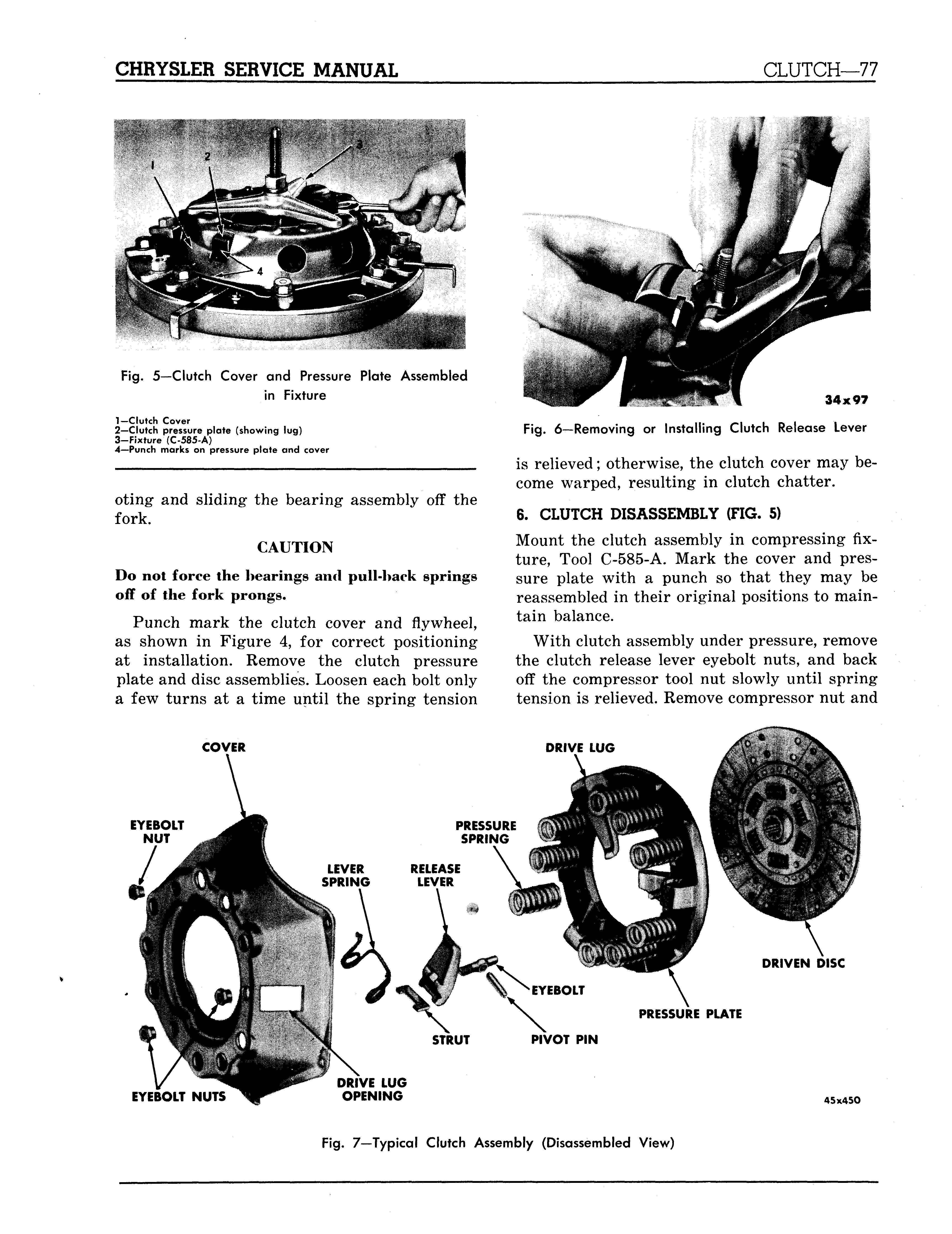
Fig. 5—Clutch Cover and Pressure Plate Assembled in Fixture
1—Clutch Cover 2—Clutch pressure plate (showing lug) 3-Fixture (C-585-A) 4—Punch marks on pressure plate and cover
oting and sliding the bearing assembly off the fork.
CAUTION Do not force the hearings and pull-hack springs off of the fork prongs.
Punch mark the clutch cover and flywheel, as shown in Figure 4, for correct positioning at installation. Remove the clutch pressure plate and disc assemblies. Loosen each bolt only a few turns at a time until the spring tension
COVER 34x97
Fig. 6—Removing or Installing Clutch Release Lever
is relieved; otherwise, the clutch cover may become warped, resulting in clutch chatter.
6. CLUTCH DISASSEMBLY (FIG. 5)
Mount the clutch assembly in compressing fixture, Tool C-585-A. Mark the cover and pressure plate with a punch so that they may be reassembled in their original positions to maintain balance.
With clutch assembly under pressure, remove the clutch release lever eyebolt nuts, and back off the compressor tool nut slowly until spring tension is relieved. Remove compressor nut and
EYEBOLT NUTS DRIVE LUG OPENING
45x450
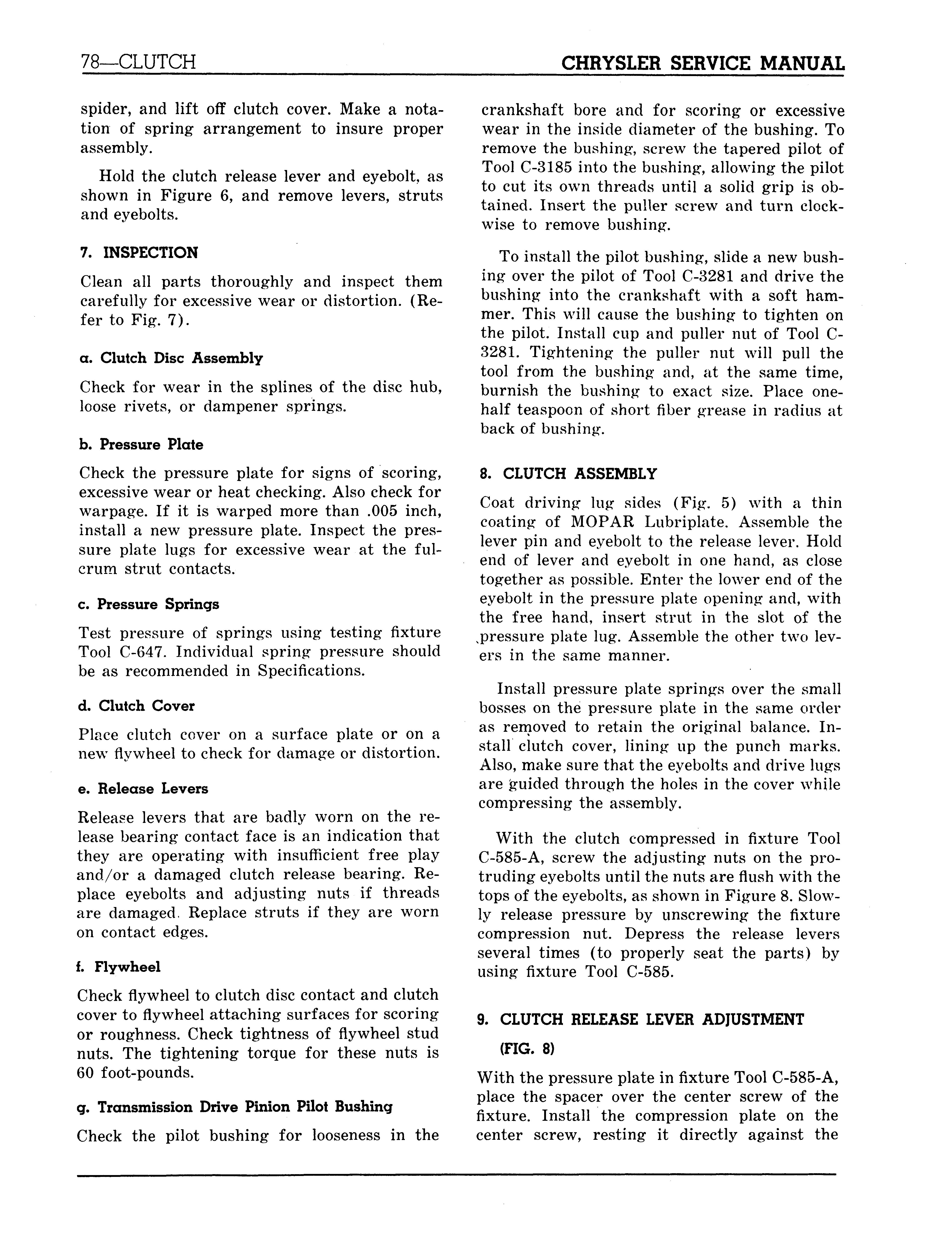
spider, and lift off clutch cover. Make a notation of spring arrangement to insure proper assembly.
Hold the clutch release lever and eyebolt, as shown in Figure 6, and remove levers, struts and eyebolts.
7. INSPECTION
Clean all parts thoroughly and inspect them carefully for excessive wear or distortion. (Refer to Fig. 7).
a. Clutch Disc Assembly
Check for wear in the splines of the disc hub, loose rivets, or dampener springs.
b. Pressure Plate
Check the pressure plate for signs of scoring, excessive wear or heat checking. Also check for warpage. If it is warped more than .005 inch, install a new pressure plate. Inspect the pressure plate lugs for excessive wear at the fulcrum strut contacts.
c. Pressure Springs
Test pressure of springs using testing fixture Tool C-647. Individual spring pressure should be as recommended in Specifications.
d. Clutch Cover
Place clutch cover on a surface plate or on a new flywheel to check for damage or distortion.
e. Release Levers
Release levers that are badly worn on the release bearing contact face is an indication that they are operating with insufficient free play and/or a damaged clutch release bearing. Replace eyebolts and adjusting nuts if threads are damaged. Replace struts if they are worn on contact edges.
f. Flywheel
Check flywheel to clutch disc contact and clutch cover to flywheel attaching surfaces for scoring or roughness. Check tightness of flywheel stud nuts. The tightening torque for these nuts is 60 foot-pounds.
g. Transmission Drive Pinion Pilot Bushing
Check the pilot bushing for looseness in the crankshaft bore and for scoring or excessive wear in the inside diameter of the bushing. To remove the bushing, screw the tapered pilot of Tool C-3185 into the bushing, allowing the pilot to cut its own threads until a solid grip is obtained. Insert the puller screw and turn clockwise to remove bushing.
To install the pilot bushing, slide a new bushing over the pilot of Tool C-3281 and drive the bushing into the crankshaft with a soft hammer. This will cause the bushing to tighten on the pilot. Install cup and puller nut of Tool C3281. Tightening the puller nut will pull the tool from the bushing and, at the same time, burnish the bushing to exact size. Place onehalf teaspoon of short fiber grease in radius at back of bushing.
8. CLUTCH ASSEMBLY
Coat driving lug sides (Fig. 5) with a thin coating of MOPAR Lubriplate. Assemble the lever pin and eyebolt to the release lever. Hold end of lever and eyebolt in one hand, as close together as possible. Enter the lower end of the eyebolt in the pressure plate opening and, with the free hand, insert strut in the slot of the ^pressure plate lug. Assemble the other two levers in the same manner.
Install pressure plate springs over the small bosses on the pressure plate in the same order as removed to retain the original balance. Install clutch cover, lining up the punch marks. Also, make sure that the eyebolts and drive lugs are guided through the holes in the cover while compressing the assembly.
With the clutch compressed in fixture Tool C-585-A, screw the adjusting nuts on the protruding eyebolts until the nuts are flush with the tops of the eyebolts, as shown in Figure 8. Slowly release pressure by unscrewing the fixture compression nut. Depress the release levers several times (to properly seat the parts) by using fixture Tool C-585.
9. CLUTCH RELEASE LEVER ADJUSTMENT
(FIG. 8)
With the pressure plate in fixture Tool C-585-A, place the spacer over the center screw of the fixture. Install the compression plate on the center screw, resting it directly against the
Fig. 8—Adjusting Clutch Release Levers
1-Feeler blades (part of Tool C-585-A) 2—Compression plate (part of Tool C-585-A) 3-Spacers (part of Tool C-585-A) 4—Clutch release lever eyebolt 5—Clutch release lever eyebolt nut 6—Stake here to lock
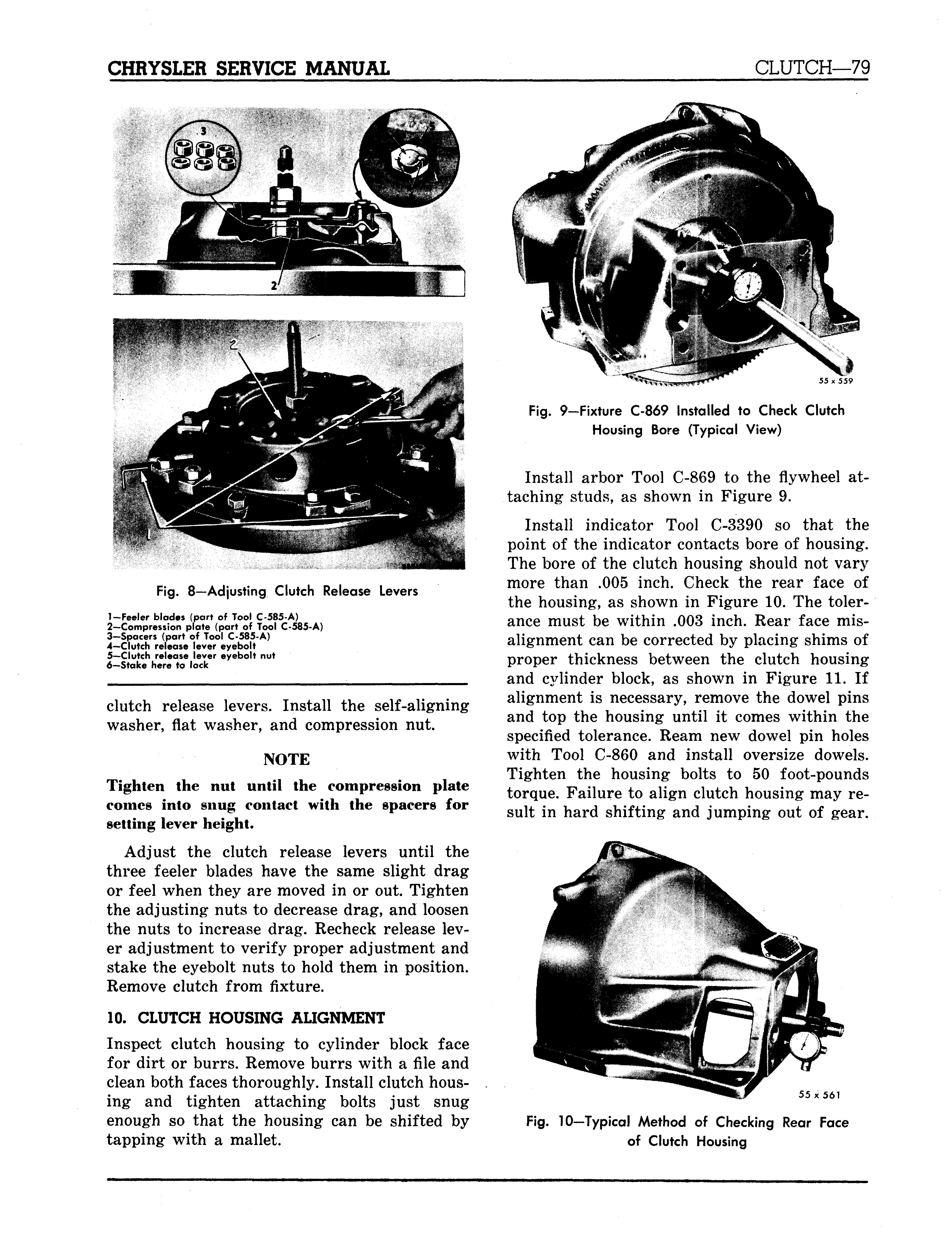
clutch release levers. Install the self-aligning washer, flat washer, and compression nut. NOTE Tighten the nut until the compression plate comes into snug contact with the spacers for setting lever height.
Adjust the clutch release levers until the three feeler blades have the same slight drag or feel when they are moved in or out. Tighten the adjusting nuts to decrease drag, and loosen the nuts to increase drag. Recheck release lever adjustment to verify proper adjustment and stake the eyebolt nuts to hold them in position. Remove clutch from fixture.
10. CLUTCH HOUSING ALIGNMENT Inspect clutch housing to cylinder block face for dirt or burrs. Remove burrs with a file and clean both faces thoroughly. Install clutch housing and tighten attaching bolts just snug enough so that the housing can be shifted by tapping with a mallet.
Fig. 9—Fixture C-869 Installed to Check Clutch Housing Bore (Typical View)
Install arbor Tool C-869 to the flywheel attaching studs, as shown in Figure 9.
Install indicator Tool C-3390 so that the point of the indicator contacts bore of housing. The bore of the clutch housing should not vary more than .005 inch. Check the rear face of the housing, as shown in Figure 10. The tolerance must be within .003 inch. Rear face misalignment can be corrected by placing shims of proper thickness between the clutch housing and cylinder block, as shown in Figure 11. If alignment is necessary, remove the dowel pins and top the housing until it comes within the specified tolerance. Ream new dowel pin holes with Tool C-860 and install oversize dowels. Tighten the housing bolts to 50 foot-pounds torque. Failure to align clutch housing may result in hard shifting and jumping out of gear.
55 x561


