12 minute read
Removal and Inspection of Differential and Carrier Assembly

from 1956 Chrysler C-71 (Windsor) C-72 (New Yorker) C-300B(Chrysler) C-73(Custom Imperial) Service Manual

.0125 inch shim. The end play is then .0425 inch minus .038 inch, equals .0045 inch.
Remove right axle shaft and lubricate bearing. Install axle shaft, bearing and shim and complete the assembly. If dial indicator shows less than .003 inch, or more than .008 inch end play, remove brake support plate and oil seal, and add or remove shims, as required, to obtain desired axle shaft end play. CAUTION
When adjusting axle shaft end play, equal thickness of shims should be removed or installed on both sides of axle housing to maintain the centralized position of axle shaft thrust block.
After axle shaft end play has been checked or corrected, install brake drum and wheel assembly. Tighten axle shaft nuts to a minimum of 145 foot-pounds torque. Install cotter keys and remove jack from car.
6. REMOVAL AND INSPECTION OF
DIFFERENTIAL AND CARRIER ASSEMBLY a. Removal Raise car off floor and back off the brake shoes. Remove wheel hub and drum assembly and rear axle shaft and proceed as follows:
Disconnect rear universal joint and drop propeller shaft. Drain lubricant from differential housing.
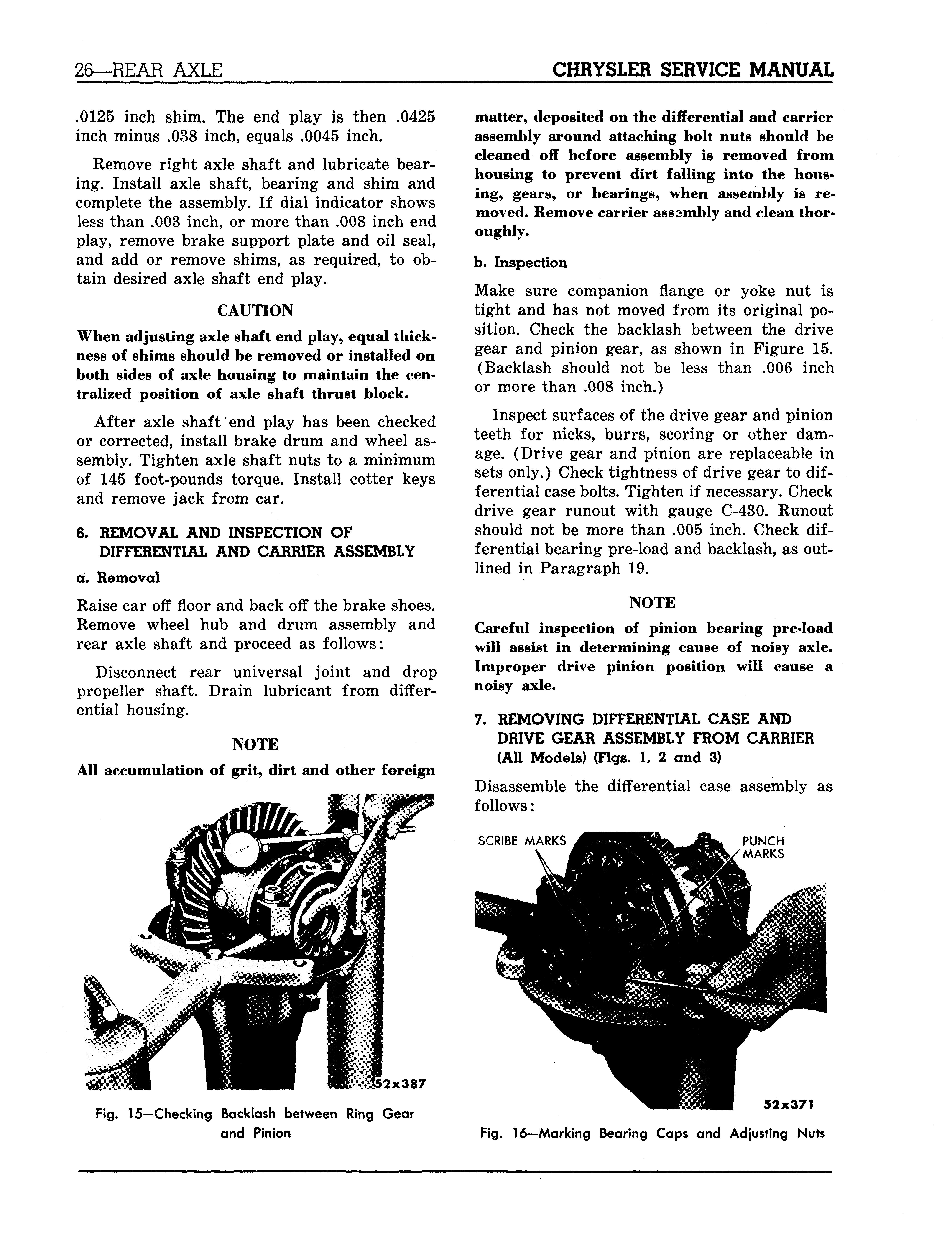
NOTE All accumulation of grit, dirt and other foreign matter, deposited on the differential and carrier assembly around attaching bolt nuts should be cleaned off before assembly is removed from housing to prevent dirt falling into the housing, gears, or bearings, when assembly is removed. Remove carrier assembly and clean thoroughly. b. Inspection Make sure companion flange or yoke nut is tight and has not moved from its original position. Check the backlash between the drive gear and pinion gear, as shown in Figure 15. (Backlash should not be less than .006 inch or more than .008 inch.)
Inspect surfaces of the drive gear and pinion teeth for nicks, burrs, scoring or other damage. (Drive gear and pinion are replaceable in sets only.) Check tightness of drive gear to differential case bolts. Tighten if necessary. Check drive gear runout with gauge C-430. Runout should not be more than .005 inch. Check differential bearing pre-load and backlash, as outlined in Paragraph 19.
NOTE Careful inspection of pinion bearing pre-load will assist in determining cause of noisy axle. Improper drive pinion position will cause a noisy axle.
7. REMOVING DIFFERENTIAL CASE AND
DRIVE GEAR ASSEMBLY FROM CARRIER (All Models) (Figs. 1, 2 and 3) Disassemble the differential case assembly as follows:
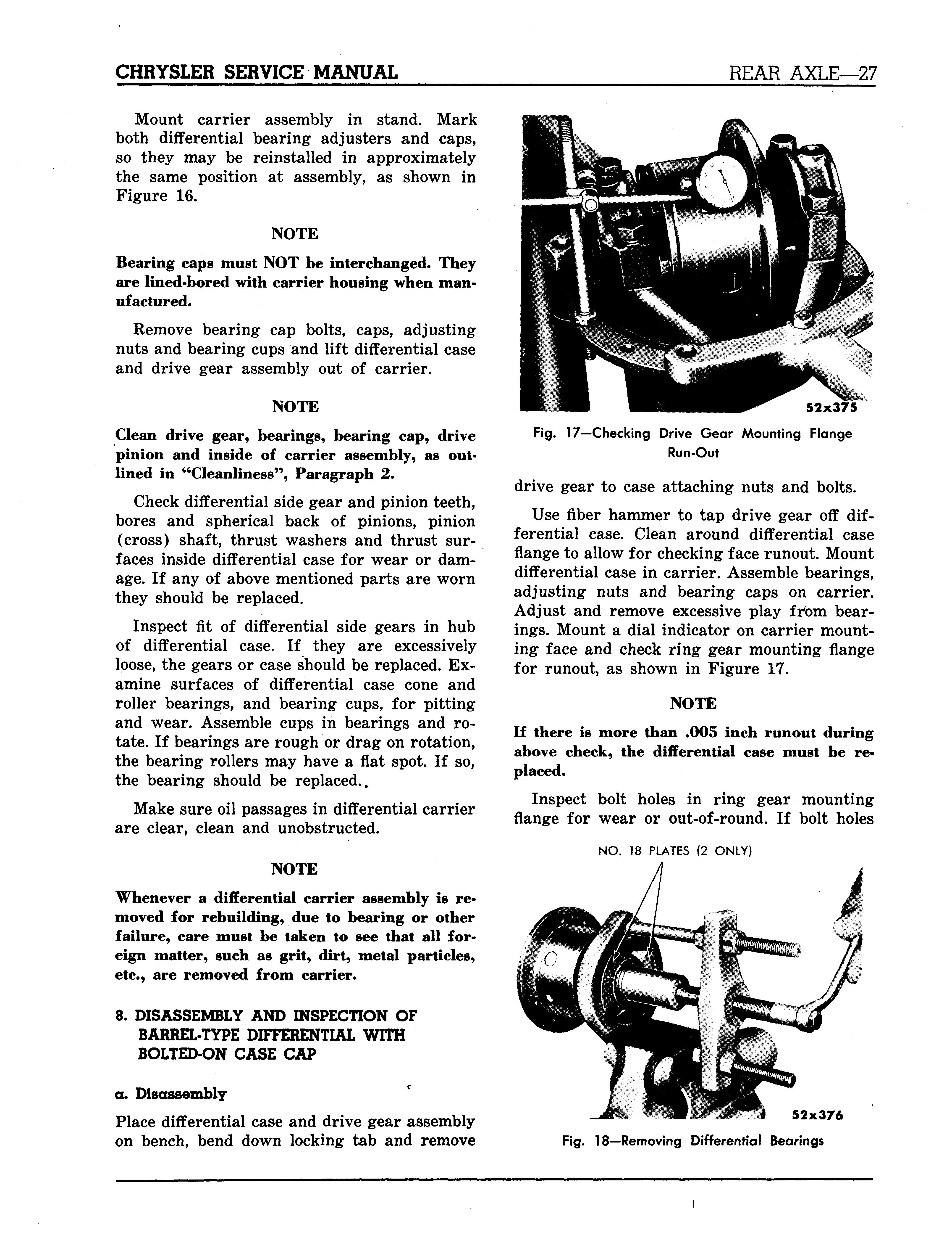
SCRIBE MARKS PUNCH MARKS
52x387
Fig. 15—Checking Backlash between Ring Gear
and Pinion 52x371
Fig. 16—Marking Bearing Caps and Adjusting Nuts
Mount carrier assembly in stand. Mark both differential bearing adjusters and caps, so they may be reinstalled in approximately the same position at assembly, as shown in Figure 16.
NOTE
Bearing caps must NOT be interchanged. They are lined-bored with carrier housing when manufactured.
Remove bearing cap bolts, caps, adjusting nuts and bearing cups and lift differential case and drive gear assembly out of carrier.
NOTE
Clean drive gear, bearings, bearing cap, drive pinion and inside of carrier assembly, as outlined in "Cleanliness", Paragraph 2.
Check differential side gear and pinion teeth, bores and spherical back of pinions, pinion (cross) shaft, thrust washers and thrust surfaces inside differential case for wear or damage. If any of above mentioned parts are worn they should be replaced.
Inspect fit of differential side gears in hub of differential case. If they are excessively loose, the gears or case should be replaced. Examine surfaces of differential case cone and roller bearings, and bearing cups, for pitting and wear. Assemble cups in bearings and rotate. If bearings are rough or drag on rotation, the bearing rollers may have a flat spot. If so, the bearing should be replaced..
Make sure oil passages in differential carrier are clear, clean and unobstructed.
NOTE
Whenever a differential carrier assembly is removed for rebuilding, due to bearing or other failure, care must be taken to see that all foreign matter, such as grit, dirt, metal particles, etc., are removed from carrier.
8. DISASSEMBLY AND INSPECTION OF
BARREL-TYPE DIFFERENTIAL WITH
BOLTED-ON CASE CAP
a. Disassembly Place differential case and drive gear assembly on bench, bend down locking tab and remove
52x375 Fig. 17—Checking Drive Gear Mounting Flange Run-Out
drive gear to case attaching nuts and bolts.
Use fiber hammer to tap drive gear off differential case. Clean around differential case flange to allow for checking face runout. Mount differential case in carrier. Assemble bearings, adjusting nuts and bearing caps on carrier. Adjust and remove excessive play frtan bearings. Mount a dial indicator on carrier mounting face and check ring gear mounting flange for runout, as shown in Figure 17.
NOTE
If there is more than .005 inch runout during above check, the differential case must be replaced.
Inspect bolt holes in ring gear mounting flange for wear or out-of-round. If bolt holes
NO. 18 PLATES (2 ONLY)
52x376 Fig. 18—Removing Differential Bearings
LOCK PIN DRIVE OUT HOLES LOCK PIN
52x377
Fig. 19—Removing the Differential Pinion Shaft Lock Pins
are out-pf-round, the ring gear will creep on the case.
Remove differential case from carrier. Fit Number 18 plates behind bearings and pull off differential bearings, using Tool C-293, as shown in Figure 18. Remove differential bearing spacers. Remove differential cap to case bolts, and tap cap lightly with a soft hammer to remove. Remove three differential pinion shaft lock pins by driving them out of case with a hammer and punch, as shown in Figure 19.
Drive the long pinion shaft out of differential case, using a brass drift and hammer.
NOTE This shaft can be identified as having only one retaining pin.
Lift out rear axle drive shaft thrust block. Drive the short pinion shafts out of case, and lift out the pinion shaft block.
NOTE The short pinion shaft sides of the block are punch marked for identification.
Lift out differential pinion gears, side gears and thrust washers.
b. Cleaning and Inspection Clean all parts thoroughly in a suitable solvent and blow dry with compressed air. Remove any chips or foreign material from carrier hous-
ing. Inspect all machined surfaces for nicks, burrs or scratches. Inspect thrust shoulders in carrier housing (bearing cups) to make sure there are no burrs on them. The thrust shoulder must be flat, so bearing cups will seat properly. Check the differential case for cracks, fractures, distortion or damage. Install a new case if necessary. The bearings should be immersed in clean solvent and rotated by hand until clean. After cleaning, blow dry with compressed air.

CAUTION Do not spin bearings with air pressure when blowing them dry, as damage to bearings may result from this practice.
Check bearings for roughness, or brinelling. The bearings must run free and show no indication of roughness of wear. Examine bearing cups for pitting, scoring or wear. Inspect all gears for chipped or worn gear teeth. Check fit of differential side gears on axle shaft splines and differential gears on pinion shafts. Check thrust washers for wear and replace, if necessary.
NOTE
Whenever a differential carrier assembly is removed for rebuilding due to bearing or other failure, care must be taken to see that all foreign matter, such as grit, dirt, metal particles, etc., are removed from carrier.
18X722
Fig. 20—Removing Differential Case Cap Lock Pin
9. DISASSEMBLY AND INSPECTION OF
BARREL-TYPE DIFFERENTIAL WITH
SCREWED-ON CASE CAP Remove drive gear from differential case as outlined in Paragraph 8 and proceed as follows:
Mount the flange of differential case in a vise equipped with copper jaws.
Remove differential bearings with puller. On Model C-70 use Number 83 adapter and Number 41 plug, puller set Tool DD-914.
Remove the differential case cap locking pins by center punching, and drilling, as shown in Figure 20. Remove shell of pin left in hole with a punch. The differential case cap is .001 to .002 inch larger than differential case body in which it fits. The case must be expanded by heating for easy removal of case cap. The case will be damaged, if any attempt is made to remove cap without heating.
Heat outside of the case (not cap) with torch. Keep the flame moving around the case to assure even heating. Try a piece of ordinary soft solder on case, from time to time. When the solder starts to melt at approximately 360 to 400 degrees F., the case will be hot as it can get without damaging the thrust washers.
When case is just hot enough to melt soft solder, loosen cap with a blunt drift and a heavy hammer and quickly unscrew the cap from case, with Tool DD-921, as shown in Figure 21. The parts can now be immersed in oil to cool for subsequent handling.
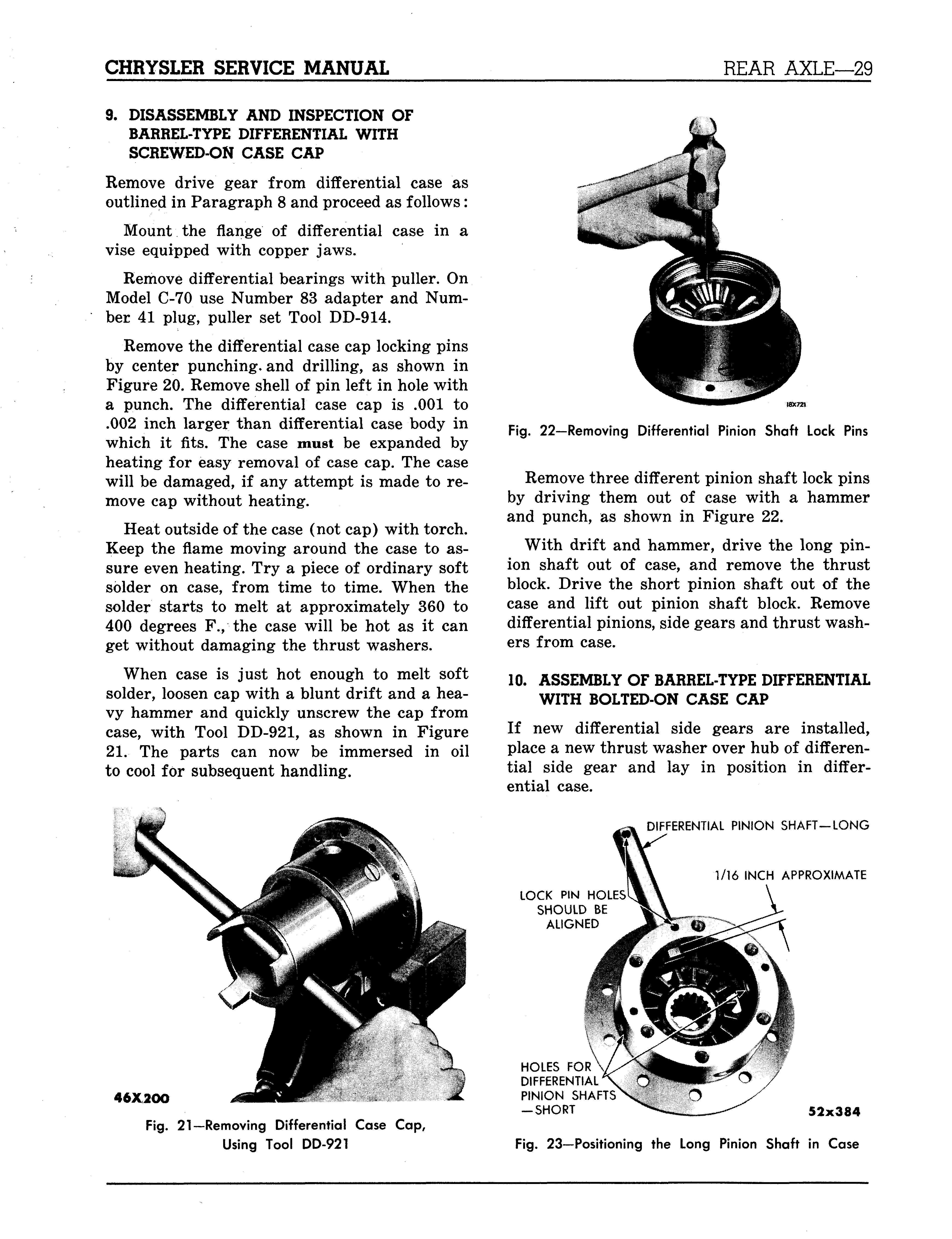
Fig. 22—Removing Differential Pinion Shaft Lock Pins
Remove three different pinion shaft lock pins by driving them out of case with a hammer and punch, as shown in Figure 22.
With drift and hammer, drive the long pinion shaft out of case, and remove the thrust block. Drive the short pinion shaft out of the case and lift out pinion shaft block. Remove differential pinions, side gears and thrust washers from case.
10. ASSEMBLY OF BARREL-TYPE DIFFERENTIAL
WITH BOLTED-ON CASE CAP If new differential side gears are installed, place a new thrust washer over hub of differential side gear and lay in position in differential case.
DIFFERENTIAL PINION SHAFT—LONG
LOCK PIN HOLES SHOULD BE ALIGNED 1/16 INCH APPROXIMATE
46X2OO
Fig. 21—Removing Differential Case Cap, Using Tool DD-921
HOLES FOR DIFFERENTIAL PINION SHAFTS — SHORT 5 2 x 3 84
Fig. 23—Positioning the Long Pinion Shaft in Case
Line up the locking pin hole in the long pinion shaft with hole in the differential case pinion boss (opposite boss has no pin hole). Drive pinion shaft in case until it protrudes about %6 inch on inside of case, as shown in Figure 23.
Place a pinion thrust washer on pinion so that the concave side faces pinion. Install pinion and thrust washer on end of shaft that protrudes through case. Tap shaft in case, while holding pinion up against case, until end of shaft is even with edge of pinion.
Insert the pinion shaft block with punch marked sides facing the short shaft holes. Install axle drive shaft thrust block and continue to drive shaft through pinion shaft block and rear axle drive shaft thrust block.
Install opposite pinion and thrust washer. Drive shaft into final position in case, making sure locking pin holes are lined up.
Drive one of the short pinion shafts into either of the remaining holes until shaft protrudes about yl6 inch on inside of case. (Be sure lock pin holes line up.) Install pinion and thrust washer and continue to drive shaft until shaft enters hole in pinion shaft block. Install the other short shaft, washer and gear in the same manner.
Lock three pinion shafts into case by installing three new locking pins in holes, driving pin ends approximately yiQ inch below machined surface of case.
Assemble thrust washer and differential side gear in cap. Using attaching cap screws as guides, position cap on differential case, and tap into position with fiber hammer.
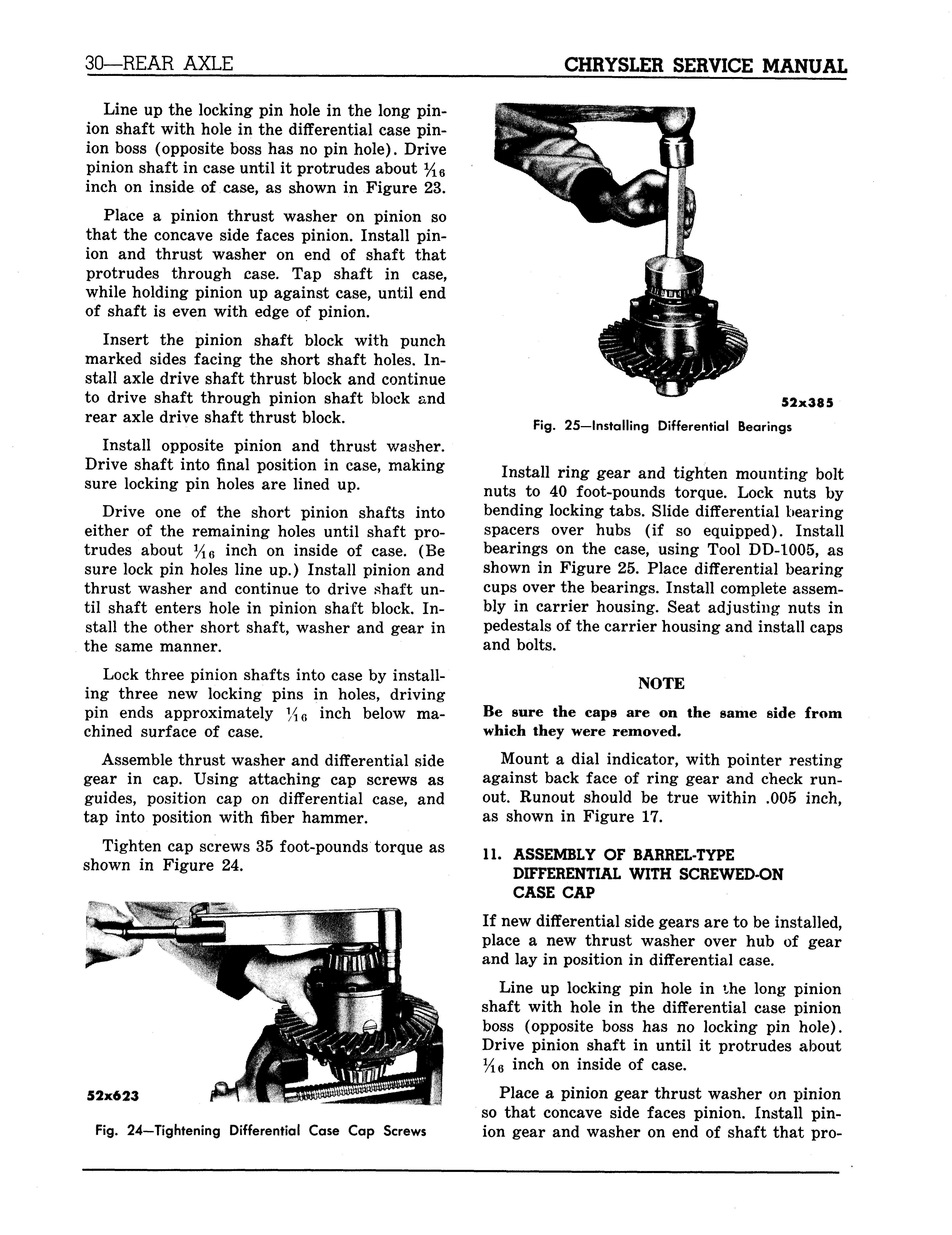
Tighten cap screws 35 foot-pounds torque as shown in Figure 24.
52x623
Fig. 24—Tightening Differential Case Cap Screws 52x385 Fig. 25—Installing Differential Bearings
Install ring gear and tighten mounting bolt nuts to 40 foot-pounds torque. Lock nuts by bending locking tabs. Slide differential bearing spacers over hubs (if so equipped). Install bearings on the case, using Tool DD-1005, as shown in Figure 25. Place differential bearing cups over the bearings. Install complete assembly in carrier housing. Seat adjusting nuts in pedestals of the carrier housing and install caps and bolts.
NOTE Be sure the caps are on the same side from which they were removed.
Mount a dial indicator, with pointer resting against back face of ring gear and check runout. Runout should be true within .005 inch, as shown in Figure 17.
11. ASSEMBLY OF BARREL-TYPE
DIFFERENTIAL WITH SCREWED-ON
CASE CAP
If new differential side gears are to be installed, place a new thrust washer over hub of gear and lay in position in differential case.
Line up locking pin hole in the long pinion shaft with hole in the differential case pinion boss (opposite boss has no locking pin hole). Drive pinion shaft in until it protrudes about y16 inch on inside of case.
Place a pinion gear thrust washer on pinion so that concave side faces pinion. Install pinion gear and washer on end of shaft that pro-
USE BALL END PUNCH TO PEEN METAL OVER TOP OF PINS—PEEN METAL ON DRIVE GEAR SIDE OF PIN HOLE
51x164
Fig. 26—Staking Differential Case Cap Lock Pins
trudes. Tap shaft and hold pinion, until end of shaft is even with edge of pinion.
Insert pinion shaft block (with punch marked sides facing the short shaft holes and the side marked 1 facing up). Install thrust block and continue to drive shaft through pinion shaft thrust block and pinion shaft block. Install opposite pinion gear and thrust washer. Drive shaft into final position. Drive one of short pinion shafts into either of remaining holes, until shaft protrudes about %6 inch on inside of case. Be sure lock pin holes line up. Install pinion gear and thrust washer and continue to drive until shaft enters hole in pinion shaft block. Install the other short shaft, washer and gear in the same manner.
Lock the three pinion shafts in case (by in-
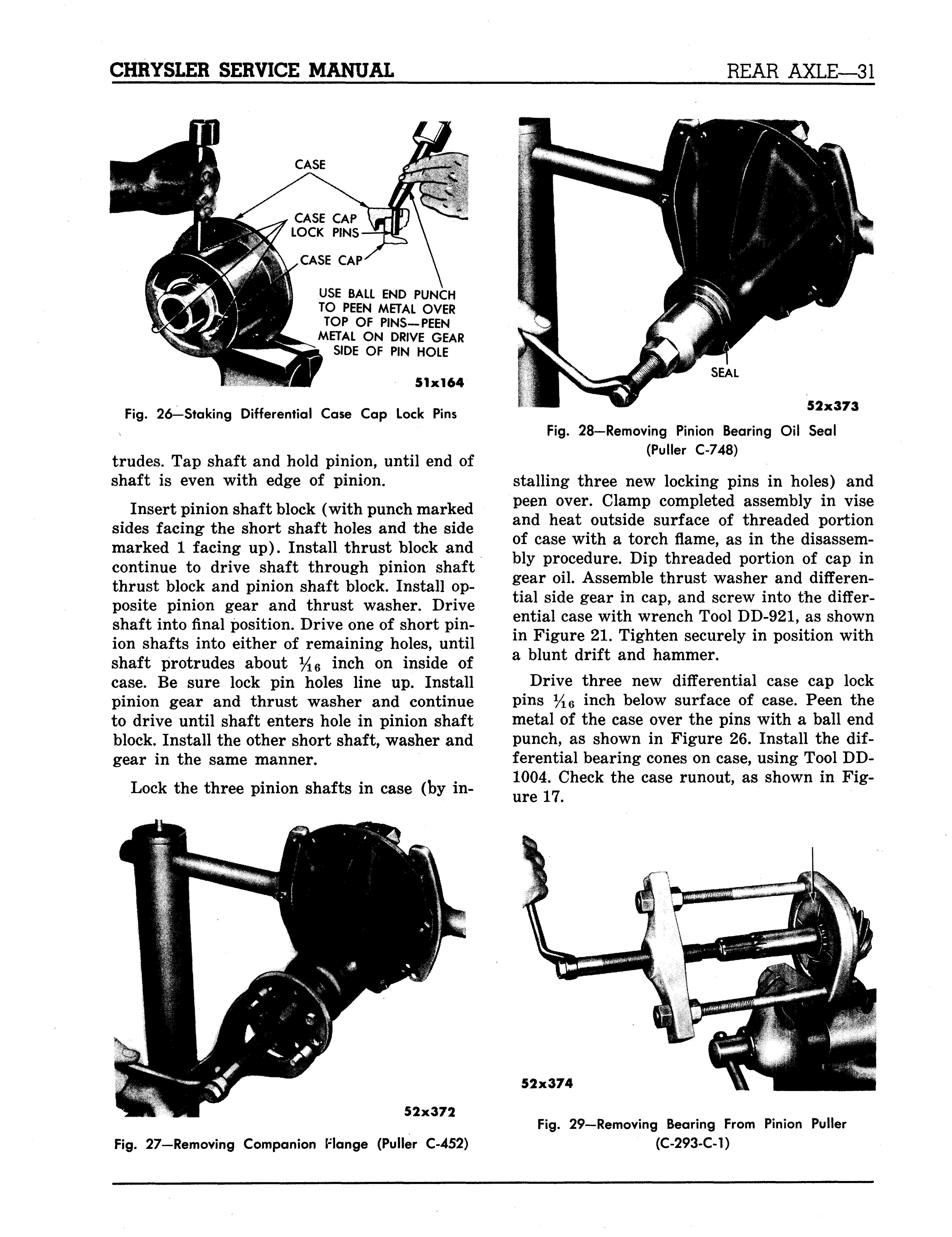
SEAL
52x373
Fig. 28—Removing Pinion Bearing Oil Seal (Puller C-748)
stalling three new locking pins in holes) and peen over. Clamp completed assembly in vise and heat outside surface of threaded portion of case with a torch flame, as in the disassembly procedure. Dip threaded portion of cap in gear oil. Assemble thrust washer and differential side gear in cap, and screw into the differential case with wrench Tool DD-921, as shown in Figure 21. Tighten securely in position with a blunt drift and hammer.
Drive three new differential case cap lock pins y1G inch below surface of case. Peen the metal of the case over the pins with a ball end punch, as shown in Figure 26. Install the differential bearing cones on case, using Tool DD1004. Check the case runout, as shown in Figure 17.
52x372
52x374
Fig. 29—Removing Bearing From Pinion Puller (C-293-C-1)


