4 minute read
Setting Axle Shaft End Play

from 1956 Chrysler C-71 (Windsor) C-72 (New Yorker) C-300B(Chrysler) C-73(Custom Imperial) Service Manual

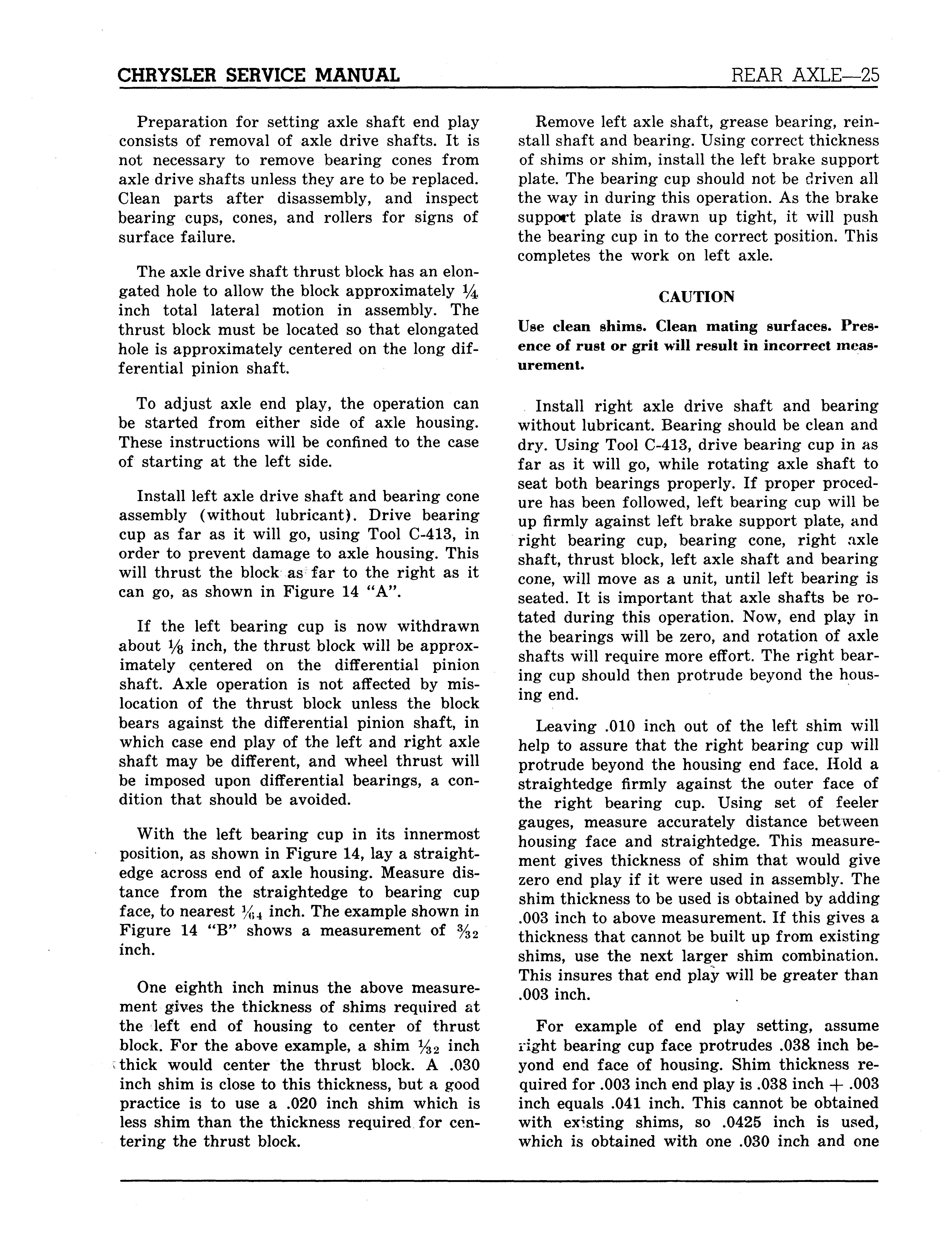
56x236
Fig. 13—Checking Axle Shaft End Play
4. REMOVING BROKEN END OF AXLE
DRIVE SHAFT
Raise car, back off brake shoes, remove wheel, drum and axle drive shaft as outlined in Paragraph 3. If break is less than eight inches from splined end of shaft, it will be necessary to remove differential and carrier assembly. If break is more than eight inches from splined end of shaft, it will be necessary to remove inner oil seal and snare inner end of axle drive shaft out through housing with a hoop.
CAUTION To avoid damage to rear axle carrier assembly, oil must be drained from differential housing and cleaned to remove chips and grit before installing new axle shaft.
Replace axle shaft and check rear axle end play, as outlined in Paragraph 5. Replace wheel hub and drum assembly and tighten axle shaft nuts to a minimum of 145 foot-pounds torque. Refill differential, and adjust brake shoes.
5. SETTING AXLE SHAFT END PLAY Rear axle shaft end play is adjusted by use of adjusting shims that are bolted between the axle housing ends and brake support plates. The shims are available in thicknesses of .005, .010, .0125, .015, and .030 inch. The correct axle end play is .003 to .008 inch. One or more shims may be required to obtain correct end play.
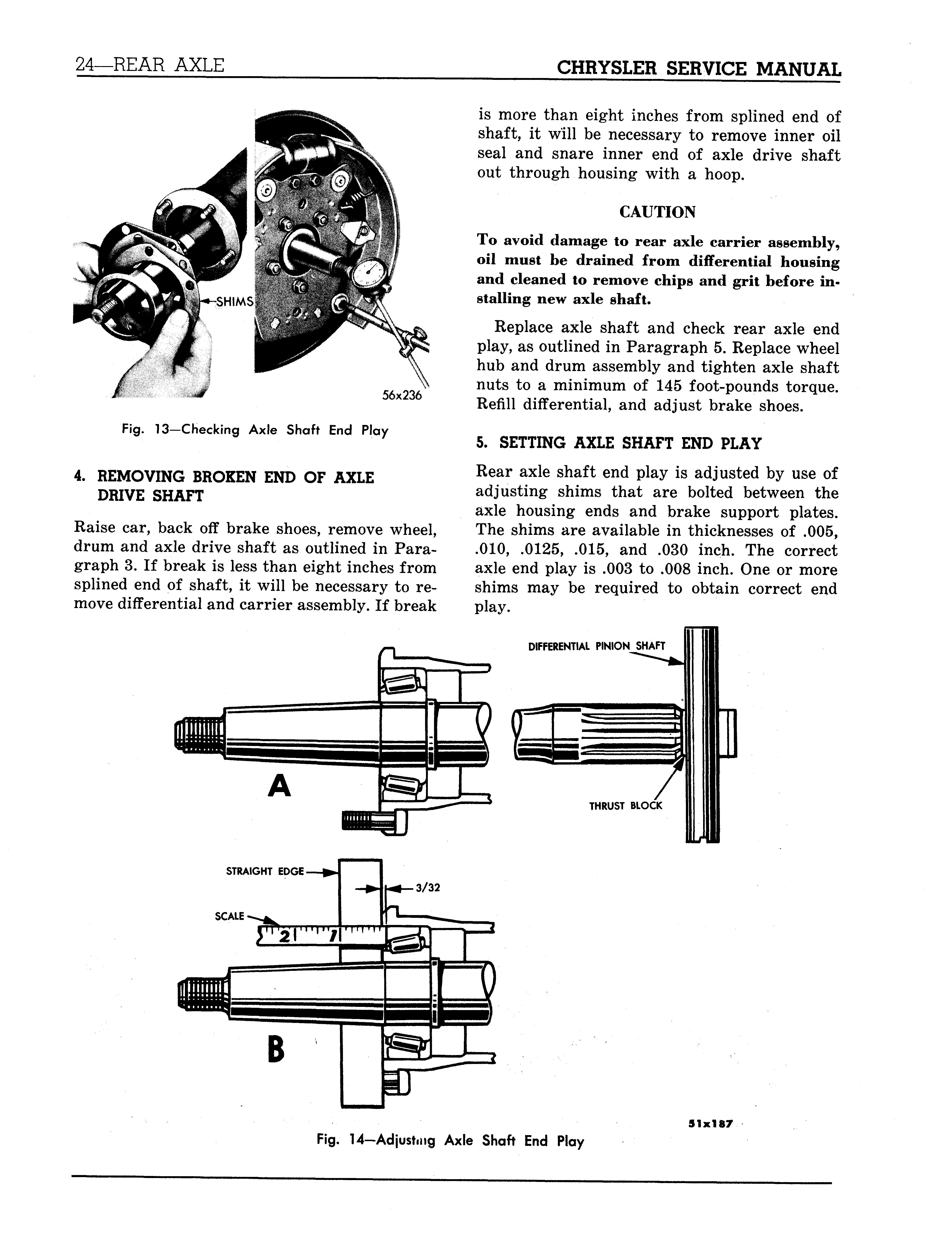
DIFFERENTIAL PINION SHAFT
Fig. 14-Adjusting Axle Shaft End Play
5 1 x 1 87
Preparation for setting axle shaft end play consists of removal of axle drive shafts. It is not necessary to remove bearing cones from axle drive shafts unless they are to be replaced. Clean parts after disassembly, and inspect bearing cups, cones, and rollers for signs of surface failure.
The axle drive shaft thrust block has an elongated hole to allow the block approximately *4 inch total lateral motion in assembly. The thrust block must be located so that elongated hole is approximately centered on the long differential pinion shaft.
To adjust axle end play, the operation can be started from either side of axle housing. These instructions will be confined to the case of starting at the left side.
Install left axle drive shaft and bearing cone assembly (without lubricant). Drive bearing cup as far as it will go, using Tool C-413, in order to prevent damage to axle housing. This will thrust the block as far to the right as it can go, as shown in Figure 14 "A".
If the left bearing cup is now withdrawn about Vs inch, the thrust block will be approximately centered on the differential pinion shaft. Axle operation is not affected by mislocation of the thrust block unless the block bears against the differential pinion shaft, in which case end play of the left and right axle shaft may be different, and wheel thrust will be imposed upon differential bearings, a condition that should be avoided.
With the left bearing cup in its innermost position, as shown in Figure 14, lay a straightedge across end of axle housing. Measure distance from the straightedge to bearing cup face, to nearest %4 inch. The example shown in Figure 14 " B" shows a measurement of %2 inch.
One eighth inch minus the above measurement gives the thickness of shims required at the left end of housing to center of thrust block. For the above example, a shim %2 inch thick would center the thrust block. A .030 inch shim is close to this thickness, but a good practice is to use a .020 inch shim which is less shim than the thickness required for centering the thrust block.
Remove left axle shaft, grease bearing, reinstall shaft and bearing. Using correct thickness of shims or shim, install the left brake support plate. The bearing cup should not be driven all the way in during this operation. As the brake support plate is drawn up tight, it will push the bearing cup in to the correct position. This completes the work on left axle.
CAUTION Use clean shims. Clean mating surfaces. Presence of rust or grit will result in incorrect measurement.
Install right axle drive shaft and bearing without lubricant. Bearing should be clean and dry. Using Tool C-413, drive bearing cup in as far as it will go, while rotating axle shaft to seat both bearings properly. If proper procedure has been followed, left bearing cup will be up firmly against left brake support plate, and right bearing cup, bearing cone, right axle shaft, thrust block, left axle shaft and bearing cone, will move as a unit, until left bearing is seated. It is important that axle shafts be rotated during this operation. Now, end play in the bearings will be zero, and rotation of axle shafts will require more effort. The right bearing cup should then protrude beyond the housing end.
Leaving .010 inch out of the left shim will help to assure that the right bearing cup will protrude beyond the housing end face. Hold a straightedge firmly against the outer face of the right bearing cup. Using set of feeler gauges, measure accurately distance between housing face and straightedge. This measurement gives thickness of shim that would give zero end play if it were used in assembly. The shim thickness to be used is obtained by adding .003 inch to above measurement. If this gives a thickness that cannot be built up from existing shims, use the next larger shim combination. This insures that end play will be greater than .003 inch.
For example of end play setting, assume right bearing cup face protrudes .038 inch beyond end face of housing. Shim thickness required for .003 inch end play is .038 inch + .003 inch equals .041 inch. This cannot be obtained with existing shims, so .0425 inch is used, which is obtained with one .030 inch and one