1 minute read
Removal of Axle Drive Pinion from Carrier (All Models

from 1956 Chrysler C-71 (Windsor) C-72 (New Yorker) C-300B(Chrysler) C-73(Custom Imperial) Service Manual

12. REMOVAL OF AXLE DRIVE PINION FROM
CARRIER (ALL MODELS)
a. Removal
With carrier assembly mounted in stand, remove companion flange retaining nut and washer. On all models, remove drive pinion flange with utility puller Tool C-549, as shown in Figure 27.
Remove pinion shaft oil seal. Use Tool DD993 to remove drive pinion oil seal from differential carrier assembly. (Refer to Fig. 28). Remove the oil slinger, bearing cone, spacer and shims (if so equipped), pinion adjusting washer, bearing cone and pinion from carrier housing. To remove or install the rear bearing from (or on) drive pinion, use special Tool DD-914 (for Model C-70) and Tool C-293-C for all other models (Fig. 29).
NOTE When using Tool C-293-C, use Number 36
ninths nlfirk.plates also.
Remove both bearing cups from carrier assembly with a suitable drift. Be sure to drive both cups out evenly.
b. Cleaning and Inspection
Clean all parts thoroughly in a suitable solvent and blow dry with compressed air. Remove any chips or foreign material from carrier housing. Inspect all machined surfaces for nicks, burrs or scratches. Inspect thrust shoulders in carrier housing (bearing cups) to make sure there are no burrs on them. The thrust shoul-
CROSS BORE TUBE COMPRESSION SLEEVE TOOL—CROSSBORE TUBE
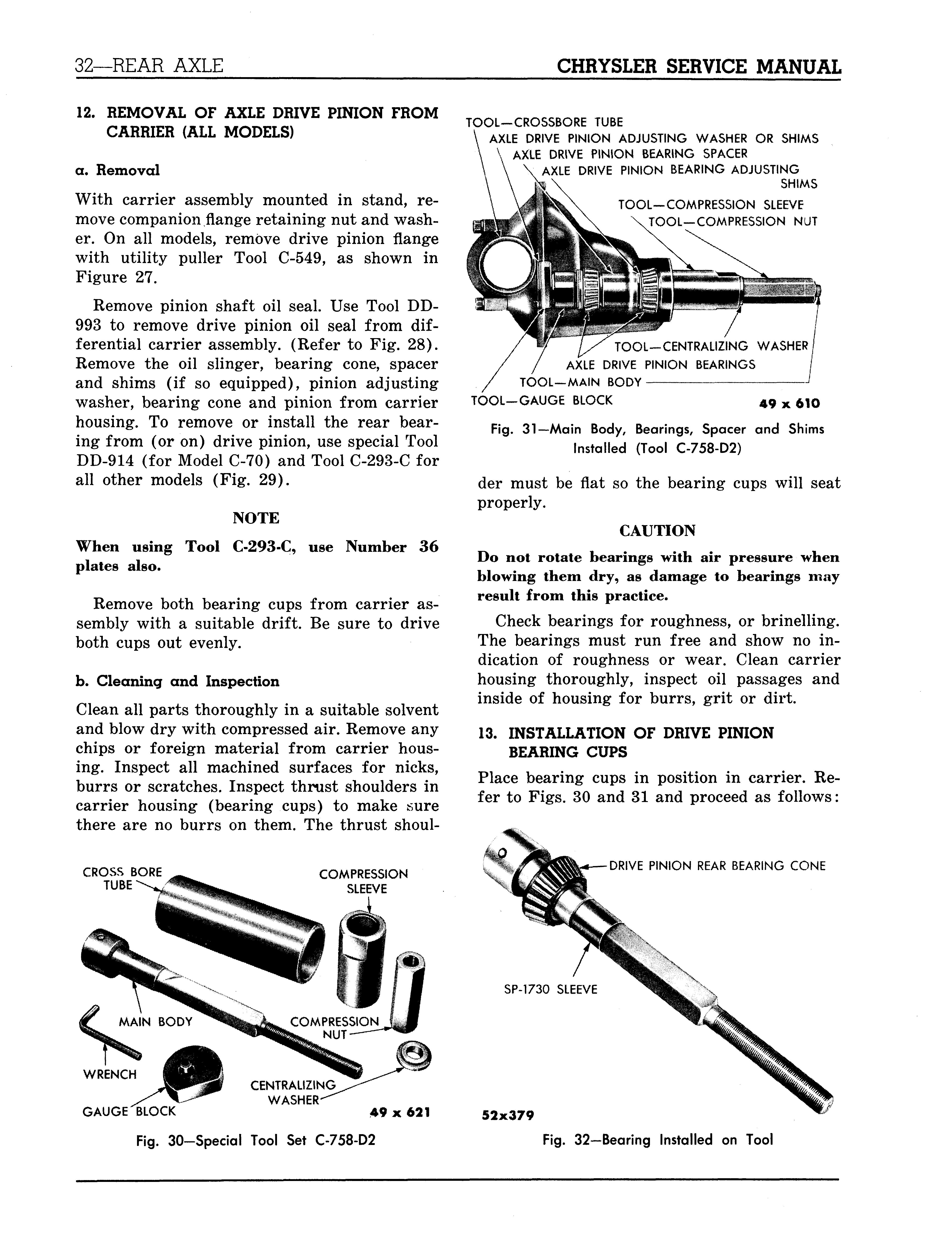
AXLE DRIVE PINION ADJUSTING WASHER OR SHIMS AXLE DRIVE PINION BEARING SPACER AXLE DRIVE PINION BEARING ADJUSTING SHIMS TOOL—COMPRESSION SLEEVE TOOL—COMPRESSION NUT
TOOL—CENTRALIZING WASHER/ AXLE DRIVE PINION BEARINGS / TOOL—MAIN BODY J TOOL—GAUGE BLOCK 49 x $10
Fig. 31—Main Body, Bearings, Spacer and Shims Installed (Tool C-758-D2)
der must be flat so the bearing cups will seat properly.
CAUTION
Do not rotate bearings with air pressure when blowing them dry, as damage to bearings may result from this practice.
Check bearings for roughness, or brinelling. The bearings must run free and show no indication of roughness or wear. Clean carrier housing thoroughly, inspect oil passages and inside of housing for burrs, grit or dirt.
13. INSTALLATION OF DRIVE PINION
BEARING CUPS
Place bearing cups in position in carrier. Refer to Figs. 30 and 31 and proceed as follows:
DRIVE PINION REAR BEARING CONE
WRENCH
GAUGE "BLOCK
49 x 621
Fig. 30-Special Tool Set C-758-D2
SP-1730 SLEEVE


