
16 minute read
Upper and Lower Control Arm to Steering Knuckle Support Pin Nut

from 1956 Chrysler C-71 (Windsor) C-72 (New Yorker) C-300B(Chrysler) C-73(Custom Imperial) Service Manual

b. Testing Armature for Ground Touch armature shaft and end of a commutator bar with pair of test lamp test prods. If lamp lights, it indicates a grounded armature. Replace grounded armature.
c. Testing Commutator Run-Out,
Refacing and Undercutting Place armature in pair of "Vee" blocks and check runout with dial indicator. Check both shaft and commutator. A bent shaft requires replacement of armature. When commutator runout exceeds .003 inch, commutator should be refaced. Remove only sufficient metal to provide a smooth, even surface. After commutator is refaced, undercut insulation between bars to depth of Ys2 inch with a thin, hacksaw blade, or Tool C-770. Undercut insulation square and full width of groove, and polish commutator with 00 sandpaper to remove burrs.
10. TESTING THE BRUSH HOLDERS AND
FIELD COILS FOR GROUND Touch each of brush holders with a test lamp prod, while holding the other test prod against starter frame. Two of brush holders that are 180 degrees apart should cause test lamp to light, as they are intentionally grounded. The other two brush holders should not cause lamp to light when tested, as they are insulated. If these insulated brush holders cause lamp to light when tested, it indicates that brush holders or field coil are grounded. Be sure brush pigtails or leads are not touching field frame.
Remove screws from field-coil-to-brush-holder leads and insulate leads from brush holders. Retest by first touching holders and then field coil leads. If field coils are grounded, inspect terminal insulation. If insulation is in good condition, test each coil separately after unsoldering connection wire. Replace grounded field coils. If brush holders are grounded, replace frame and brush holder assembly.
11. REPLACING THE FIELD COILS
A pole shoe screwdriver should be used to remove and install field coils to prevent damage to pole shoe screws and for proper tightening. Pole shoes that are loose may cause armature core to rub pole shoes. This will decrease starter efficiency and damage the armature core. 12. SERVICING THE BUSHINGS Inspect armature shaft bearing surfaces and bearings for wear by placing core in vise equipped with soft jaws. Do not squeeze tightly. Try commutator end frame, the drive end frame, and armature support bearings for wear by placing them on shafts and checking for side play. Replace commutator end frame assembly if bearing is worn. Also, replace drive end bearing if it is worn. The bearing should be well soaked in SAE 10-W Engine Oil before it is installed.
13. SERVICING THE DRIVE UNIT Place drive unit on shaft and, while holding armature, rotate pinion. The drive pinion should rotate smoothly in one direction (not necessarily easily), but should not rotate in opposite direction. If drive unit does not function properly or pinion is worn or burred, replace drive unit.
14. ASSEMBLING THE STARTER (Refer to Figure 4.) Assemble drive end parts on armature and slide assembly into field frame until end of commutator touches brushes. While holding armature against brushes with slight pressure, push brushes up and allow them to come to rest on commutator. When all brushes are seated on commutator, slide armature assembly into place. Install commutator end frames and through bolts. Make sure end frames are positioned on dowel pins, and tighten through bolts. Install solenoid switch assem-
FEELER
bly, but do not bend cotter key over until solenoid plunger travel and pinion clearance have been established.
15. ADJUSTING STARTER DRIVE GEAR (PINION) CLEARANCE (FIG. 5) Place starter assembly in vise equipped with soft jaws and tighten vise sufficiently to hold starter. Push in on solenoid plunger link (NOT THE FORK LEVER) until plunger bottoms. Measure clearance between end of pinion and pin stop with plunger seated and pinion pushed toward commutator end (Fig. 5). The clearance should be %2 inch, plus %2 inch or minus %4 inch. Adjust for proper clearance by screwing link in or out of plunger as required. Bend cotter key and test starter operation under a free running test.
16. INSTALLING THE STARTER Before installing starter in car, be sure starter and flywheel mounting surfaces are free of dirt and oil. These surfaces must be clean to make good electrical contact. Install starter from beneath car. Draw attaching bolts up tight and attach wires to solenoid switch. Lower car to floor; install battery cable and test operation of starter for proper engine cranking.
GENERATORS
17. REMOVAL The generator is mounted on a bracket attached to engine and held in place by two bolts through end frames and bracket. It is secured at top by a bolt through drive end frame and the belt tightening strap. Disconnect battery ground terminal and wire at generator armature and field terminals. Loosen generator adjusting strap bolt, push generator to left to relieve belt tension and remove generator attaching bolts and generator.
On models equipped with power steering, it is not necessary to disconnect hoses at hydraulic pump to remove generator. Remove pump at-
CAR AMMETER

56x80

Q_ '5
2 a "a I
z o
CN
taching bolts and set pump assembly to one side. Make sure pump reservoir is setting in same position as when installed to prevent oil draining from vent.
18. CHARGING CIRCUIT RESISTANCE TEST (FIG. 6) Before an output test of generator is made, charging unit should be tested for high resistance due to loose connections, damaged wiring and burned relay contacts. The generator drive belt tension should also be checked and adjusted if tension is incorrect.
Connect test equipment, as shown in Figure 6. The ammeter is connected at generator and voltmeter is attached to armature lead so that any voltage loss in test ammeter will not register on voltmeter. Start engine, increase engine speed until 10 amperes register on test ammeter, and read voltmeter. The voltage shown will be voltage drop of charging circuit and should not exceed .50 volt. A voltage drop that exceeds .50 volt indicates high resistance from a loose connection, burned relay contacts or a partially broken wire. Where voltage drop exceeds .50 volt, a-point-to-point check is required. Move one of voltmeter leads back along circuit toward other test lead connection, checking voltage at each terminal connection. A sudden drop in voltage indicates that high resistance is present between that point and last point tested. Clean relay contacts, tighten loose connections and replace damaged wiring.
Adjust belt tension by measuring with a scale applied at center of longest span between pulleys. The deflection should be *4 in cn with a 9 to 12 pound pressure. See "Cooling System" Section V Fig. 4.
19. GENERATOR OUTPUT TEST Connect equipment, as shown in Figure 6, with exception of voltmeter leads. In output test, connect voltmeter from generator armature terminal post to ground. Increase engine speed while observing the meters. A generator that is in good condition should be capable of an output in amperes that will exceed rated output slightly: approximately 15 volts at 2,300 generator r.p.m.
CAUTION The engine MUST NOT be running for more than few seconds while making above test to avoid damage to generator. Cheek generator brushes for excessive arcing and /or bounce while high output is being delivered. A rough, burned, or dirty commutator will cause arcing and bouncing at brushes.
20. DISASSEMBLY To disassemble a standard type generator (Fig. 7), remove through bolts and pull end frame from field frame. Slide armature and drive end frame assembly from generator field frame. Place armature core in vise equipped with soft jaws, and remove pulley with Tool C-3505. Remove drive key and press end frame assembly from armature. Do not remove field coils from frame at this time.
Generators used on power steering equipped cars (Fig. 8) have a ball bearing at commutator end. To remove drive end frame, remove through bolts. Pull end frame free of dowel pin and rotate end frame far enough so lugs are away from terminal posts.
Support generator in arbor press on plates against end frame lugs. Press end frame from shaft while supporting generator assembly to prevent it from falling when free. Complete disassembly operation in same manner as for a standard generator.
21. CLEANING AND INSPECTION
CAUTION
Do not immerse armature, field frame and field assembly, or bearing felts in cleaning solution. Never steam clean a generator.
Wipe above parts with a clean cloth. When cleaning ball bearings do not spin them with compressed air. Inspect field coils for burned or damaged insulation. Inspect commutator for wear and condition of soldered coil leads. An armature that has been overheated will show signs of throwing solder and will require resoldering or replacement. Inspect commutator for trueness.
Inspect bearings for wear or roughness. Replace worn or rough bearings. The bushing type bearing requires replacement of end frame assembly.


CL
•D §
I
CN
00
22. TESTING GENERATOR COMPONENTS
a. Testing Armature for Ground Place one probe from 110-volt test lamp on armature shaft and other probe at end of any commutator bar. If test lamp lights, it indicates a ground. Do not touch shaft bearing surface or commutator bar brush surface with test probe as this will pit surfaces. Replace grounded armatures.
b. Testing Armature for Short Circuit Place armature in growler and, while rotating armature, hold thin steel blade parallel to core and just above it. A shorted armature will cause steel blade to vibrate and be attracted to core. Replace shorted armature.
c. Testing Field Frame Assembly for Ground Disconnect "ARM" terminal field lead from insulated brush holder. Touch a 110-volt lamp probe to generator "FIELD" terminal post, while holding other probe against good ground on field frame (be sure brush lead terminals are not touching a ground). The lamp should not light. If lamp lights, a ground exists, and it will be necessary to determine whether ground is in field coils or field terminal post.
Remove terminal post from field frame and retest from field lead to ground. If lamp lights, field coils or connecting lead is grounded. Move connecting lead between two coils away from frame. If light still burns, ground is in field coils.
Touch one of 110-volt test lamp probes to "ARM" terminal post and field frame. If lamp lights, it indicates that either terminal post or brush holder is grounded. Remove terminal post and retest brush holder. If lamp still lights, brush holder is grounded. Replace defective parts. It is necessary to replace field frame if, insulated brush holder is grounded.
d. Testing Field Current Draw (Fig. 9) Test field coils for short circuits between windings, high resistance connections, or for improper coils, by connecting test equipment, as shown in Figure 9. Adjust battery voltage to specified voltage of 10-volts with rheostat. The reading on ammeter indicates field current draw. A current reading that exceeds 1.2 to

GENERATOR FIELD FRAME
CARBON PILE RHEOSTAT
56x1.45
1.3 amperes indicates that coil windings are shorted, or that wrong coils have been installed. A current reading that is less than specified indicates poor electrical connections or wrong field coils. Replace short* circuited or improper coils, or resolder defective connections.
23. SERVICING THE ARMATURE Reface commutator if runout exceeds .0005 inch, or if it is rough, burned, or worn so that insulation between bars is too high. Undercut insulation between commutators bars to depth of y32 inch, the full width of insulation. Metal particles are sometimes embedded in grooves following undercutting and should be removed.
24. REPLACING FIELD COILS To replace field coils, a pole shoe screwdriver, such as Tool C-3078, should be used to prevent damage to screws and to assure proper tightening when installing coils. Pole shoes that are loose will rub armature core, causing loss of efficiency and damage to armature;
25. REPLACING BRUSHES AND SPRINGS Brushes that are oil soaked or worn to % length of a new brush should be replaced. Sand new generator brushes to fit contour of commutator. With new type brush holder, it is difficult to measure spring tension (which must be done after generator is assembled). It is suggested that new springs be installed when brushes are replaced.
26. ASSEMBLING THE GENERATOR
a. Standard Generators Soak felt washers and Oilite bushing in clean engine oil. Pack ball bearing about half full with high temperature non-fiber bearing lubricant. Compress felt slightly to remove oil before installing. (Refer to Figs. 7 and 8.) Assemble drive end parts on armature before installing it in generator. Do not grip core too tightly in vise. Install retainer over snap ring before pressing bearing and end frame assembly on shaft. Install suitable sleeve over armature shaft so that pressure is applied to inner race when pressing bearing on shaft.
b. Accessory Equipment Generators On generators used with power steering or air conditioning equipment, install armature and drive end assembly in generator field frame. Brushes must be installed before end frame. Install commutator end frame and through bolts. Place felt and shield in commutator end frame and press bearing on shaft, applying pressure to inner race. Install shield.
c. Testing After Assembly The generator should be tested before it is installed on car. If proper bench test equipment is not available, it is possible to motor test generator. A generator that will motor freely with specified voltage applied will, in most cases, operate properly when driven as a generator.
27. MOTORING TEST Connect a carbon pile rheostat and test ammeter in series with positive post of 12-volt battery and generator armature terminal post. Connect a jumper lead from field terminal post to ground. Connect a jumper lead to battery negative post and generator frame. This will cause armature to rotate as a motor. Adjust battery voltage to 10 volts. The reading on test ammeter should be 3.4 to 3.9 amperes with armature turning smoothly.
28. INSTALLATION Place generator in position and install attaching bolts. Adjust drive belt tension at generating strap so there is a deflection of *4 *n cn with 9 to 12 pounds pressure. Refer to Figure 4 Cooling System Section V.
CAUTION Be sure condenser used for radio interference is properly attached to armature ("ARM") terminal post.

REGULATOR
The current and voltage regulator is designed to operate only in 12-volt, negative ground electrical system.
NOTE Do not attempt to adjust unit unless proper procedures are thoroughly understood. Otherwise, damage to entire electrical system may result.
29. PREPARATIONS FOR TESTING
Disconnect battery before attempting to remove regulator assembly or to connect test equipment. Do not connect battery again until after regulator removal and/or installation has been completed. Do not connect battery when installing test equipment until equipment is installed and all connections are protected against accidental ground. Failure to adopt these precautions may result in damage to electrical circuit parts or wiring.
Before testing regulator assembly, make sure generator drive belt tension is correct. The battery specific gravity should be 1.230 or higher. Check charging circuit resistance. The voltage drop of insulated side of circuit should not exceed .50 volt, with 10 amperes of current flowing. The ground side of charging circuit should also be tested.
30. NORMALIZING THE REGULATOR
TEMPERATURE
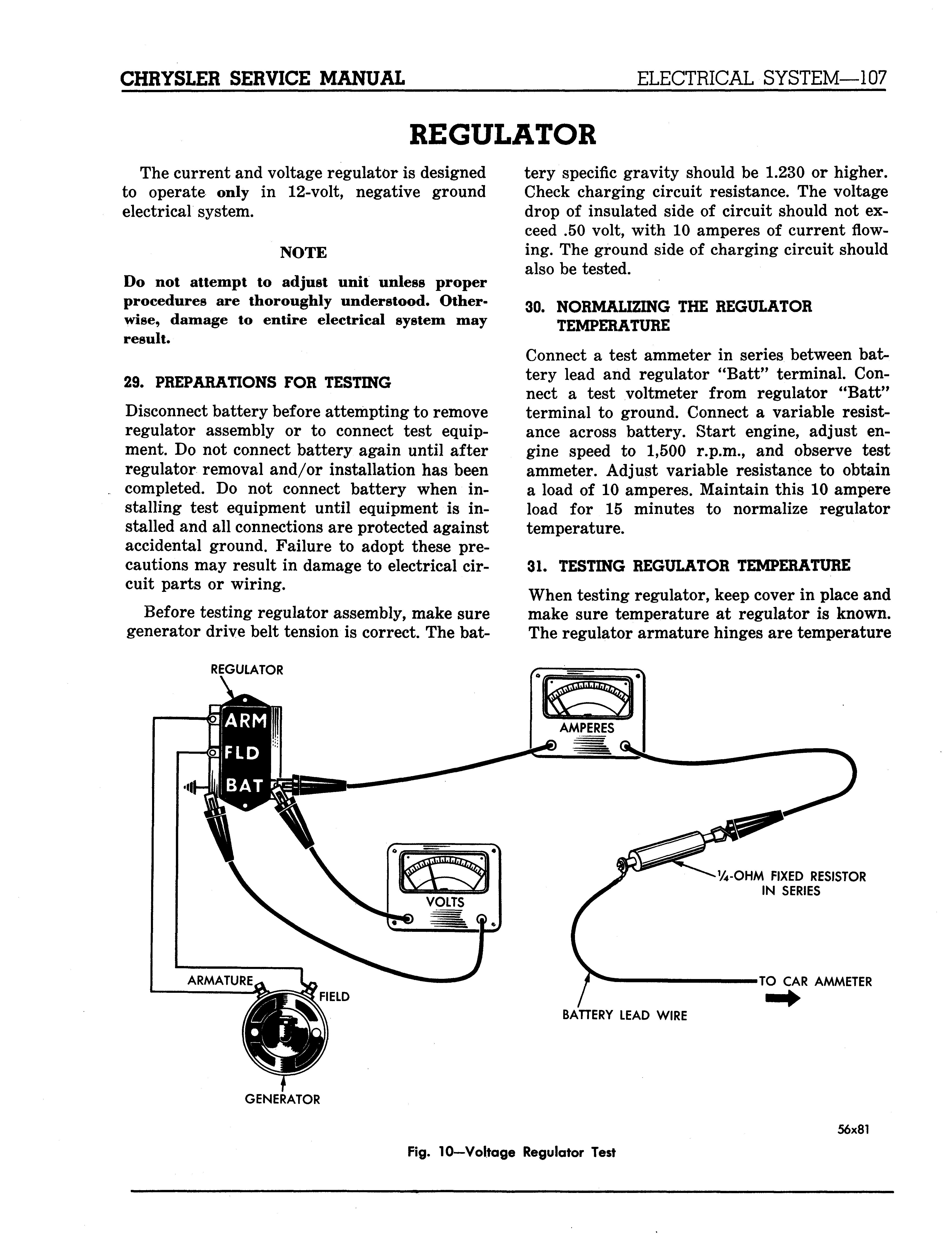
Connect a test ammeter in series between battery lead and regulator "Batt" terminal. Connect a test voltmeter from regulator "Batt" terminal to ground. Connect a variable resistance across battery. Start engine, adjust engine speed to 1,500 r.p.m., and observe test ammeter. Adjust variable resistance to obtain a load of 10 amperes. Maintain this 10 ampere load for 15 minutes to normalize regulator temperature.
31. TESTING REGULATOR TEMPERATURE
When testing regulator, keep cover in place and make sure temperature at regulator is known. The regulator armature hinges are temperature
REGULATOR
GENERATOR V4-OHM FIXED RESISTOR IN SERIES
BATTERY LEAD WIRE TO CAR AMMETER
56x81
BENDING TOOL
SPRING HANGERS
51x622
Fig. 11—Adjusting Armature Spring Tension
compensated and control will vary with temperature changes.
To measure temperature at regulator, hold an accurate Fahrenheit thermometer two inches from cover. The correct voltage setting of regulator for various temperatures with 10 amperes flowing is shown in Specifications.

500 AMPERE CARBON PILE RHEOSTAT
32. TESTING THE VOLTAGE REGULATOR
SETTING (FIG. 10) Connect test equipment (Fig. 10), start engine and operate at 1,500 r.p.m. Hold Fahrenheit thermometer 2 inches from regulator cover and note temperature reading. Observe voltage on test voltmeter. Compare voltage reading and temperature with those shown in Specifications. If adjustment is required, decrease engine speed to slow idle. Remove regulator cover and bend lower hanger of voltage regulator down to increase voltage or up to decrease voltage (Fig. 11). Replace regulator cover, increase engine speed to 1,500 r.p.m., and check temperature and voltage readings.
WARNING The regulator must be cycled by reducing engine speed low enough for cut-out relay contacts to open, before increasing engine speed to 1,500 r.p.m. when retesting after each adjustment. The regulator cover must be in place when test is made. 33. TESTING THE CURRENT REGULATOR (FIG. 12) The current regulator is temperature compen-
-NEGATIVE GROUND GENERATOR
56x82
COVER GASKET . . „ COVER
COVER FASTENING SCREWS
SPRING HANGERS BATTERY TERMINAL ARMATURE SPRINGS STATIONARY CONTACT BRIDGE CURRENT REGULATOR VOLTAGE REGULATOR j[ CUT PUT RELAY

ADJUSTING SCREWS
ARMATURE FIELD TERMINAL J SPRING
ARMATURE TERMINAL SPRING HANGER


