
9 minute read
Upper Shock Absorber Piston Rod Mounting Nut

from 1956 Chrysler C-71 (Windsor) C-72 (New Yorker) C-300B(Chrysler) C-73(Custom Imperial) Service Manual

Fig 39—Spacer Washer Thickness
49x615
The distance between gauge block and cross bore gauge bar determines thickness, of spacer washer to be used, as shown in Figure 39. The pinion washer to be used is obtained by finding thickness of the washer that slides between the cross bore gauge bar and gauge block with a slight drag. This washer will be the correct size for assembly, provided the pinion has no correction indicated on the small end of pinion head. In Manufacture, after pinion is lapped in with gear, the position of pinion for best tooth contact is etched on the small end of the pinion head as a -f or — number. This is the number of thousandths of an inch between the "best bearing" position and standard position. A -f- 2 would indicate that the pinion should be located .002 inch farther than the standard setting away from the drive gear. This amount (.002 inch) should be subtracted from the washer thickness of washer that slides between the cross bore and gauge block. For example, if gauge indicated that a carrier and rear pinion bearing combination required a pinion washer .090 inch thick, the washer used in assembly is not known until the pinion is inspected for its position mark. If it is marked 0, the spacer used in this example is .090 inch. If the pinion is marked -(- 2, the spacer should be .088 inch thick. If the pinion is marked — 2, the spacer used is .092 inch thick.
When correct washer has been selected for drive pinion, disassemble the tool from differential carrier housing. Slide pinion washer over piston shaft with chamfered side against the pinion. Install rear pinion bearing, using Tool C-3095 and a suitable arbor press. Install the pinion in differential carrier. Slide bearing spacer, bearing pre-load shim pack, bearing cone and oil slinger over shaft and down into position. Install a new oil seal, using driver Tool DD-807, as shown in Figure 40. Install companion flange, washer and nut. Tighten to 240 minimum foot-pounds torque.
17. PINION PRE-LOAD AND PINION SETTING (C-72, C-73, C-70 AND C-71 TOWN AND
COUNTRY WAGON AND POWER
PACKAGE EQUIPPED CARS
The above models use a large bearing at rear of drive pinion. The shoulder is close to front bearing, so enlarged section of pinion shaft performs the function of spacing the pinion bearings.
Adjustment of bearing pre-load is left to a thick spacer (approximately %6 inch), available in various thicknesses, and selected to give pre-load within limits specified. Pinion bearing spacers are available in fifteen different sizes as follows:
Spacer Thickness .175 in. .191 in.
177 in. 179 in.
181 in.
183 in.
185 in.
187 in.
189 in. .193 in .195 in
.197 in
.199 in
.201 in
.203 in
52x383
NO WASHER OR SPACER
ASSY. 1327868
P—561
PINION LOCATING WASHER
\ ^ \ PINION BEARING PRELOAD SPACER PRE-DETERMINED PINION LOCATING 1327832 OR CORRECT SIZE WASHER 1327853 OR CORRECT SIZE _ \ SP^l371^V^-^Sp_1
51 x 9 9 9A

P-Plug SP-Spacer
Fig. 41—Setting Pinion Bearing Pre-Load with Tool C-758-D2
To check and adjust pinion bearing pre-load, refer to Figure 41, and proceed as follows:
Assemble spacer SP-1371 to main section of tool and install spacer SP-1370. Correct pinion bearing pre-load should have a drag torque of not more than 25 to 35 inch-pounds with pinion seal removed. Slide pinion rear bearing over spacer SP-1370 and up against spacer SP-1371. Insert tool, as assembled, into carrier housing. Slide front bearing over tool shaft and into its proper position in bearing cup.
Tighten tool compression nut so the torque required to rotate the tool assembly on bearings is 25 to 35 inch-pounds, with the bearing lubricated with hypoid gear oil. Assemble gauge block SP-528 to main screw. Place SP-561 bearing arbor in differential carrier bearing supports, as shown in Figure 41.
NOTE Remove any burrs or upsets in bearing supports before installing bearing arbor, as arbor must be securely seated in bottom of bearing bores. Carefully tighten retaining bolts 10 foot-pounds torque.
Select a pinion washer of sufficient thickness so that it will just pass between gauge block end of setting tool and machined surface of arbor, as shown in Figure 39.
For example, if a .090 inch washer can be inserted, but a .092 washer cannot be forced between the two surfaces by hand, the .090 inch washer should be used even though it might feel loose. Check end of drive pinion as it should indicate the amount that should be added or subtracted from washer that was selected in above check.
Example: If mark on pinion shaft indicated + 2, a .002 inch thinner washer should be used for final assembly. If spacer selected by the use of tool is .090 inch, it is necessary to deduct .002 inch. Therefore, the correct washer for final assembly would be .088 inch.
ential carrier housing. Add washer selected to the tool, between spacer SP-1371 and pinion rear bearing. Add spacer SP-1370 and the pinion bearing adjusting spacer (that was removed from the axle at disassembly). Insert tool assembly in carrier housing. Slide front bearing on the shaft and into position in its cup. Install the tool spacer, nut and washer. Tighten tool 250 minimum foot-pounds torque as shown in Figure 35. Turn the tool with a speed wrench to permit bearings to seat. When bearings are seated, check bearing pre-load by revolving tool, using an inch-pound torque wrench, as shown in Figure 36.
The correct bearing pre-load should be 25-35 inch-pounds torque.
If the bearing adjustment does not conform to above specifications, it will be necessary to change the adjustment by using a thicker or thinner bearing spacer. A thicker spacer should be used if the pre-load is too great or a thinner spacer if the pre-load is not sufficient.
When the correct spacer has been selected for drive pinion bearings, disassemble tool from the differential carrier housing.
Slide the pinion washer over the pinion shaft with the chamfered side against the pinion. Install the rear pinion bearing, using Tool C-3095 and a suitable arbor press (See Fig. 42). Install pinion in the differential carrier. Slide the bearing adjusting spacer, bearing and oil slinger over shaft and down into position. Install a new oil seal, using driver Tool DD-807, as shown in Figure 43. Install the companion

PRESS
TOOL
52x383
Fig. 43—Installing the Drive Pinion Oil Seal
flange, washer and nut. Tighten to 250 minimum foot-pounds torque.
18. SETTING DIFFERENTIAL BEARING PRE-
LOAD AND BACKLASH (ALL MODELS) Differential bearing pre-load and backlash between the drive gear and pinion are obtained after pinion bearing pre-load and pinion settings, as described in Paragraph 17.
Place the differential bearing cups over bearings and install complete assembly in carrier housing. Seat the adjusters in the pedestals of carrier housing and install caps and bolts.
NOTE Be sure the caps are on the same side from which they were removed.
REAR BEARING CONE
DRIVE PINION
52x382 52x386
Mount a dial indicator with pointer resting against the back face of ring gear and check runout. Runout should be true within .005 inch, as shown in Figure 44.
In order to make certain that differential bearings and caps are properly seated, proceed as follows:
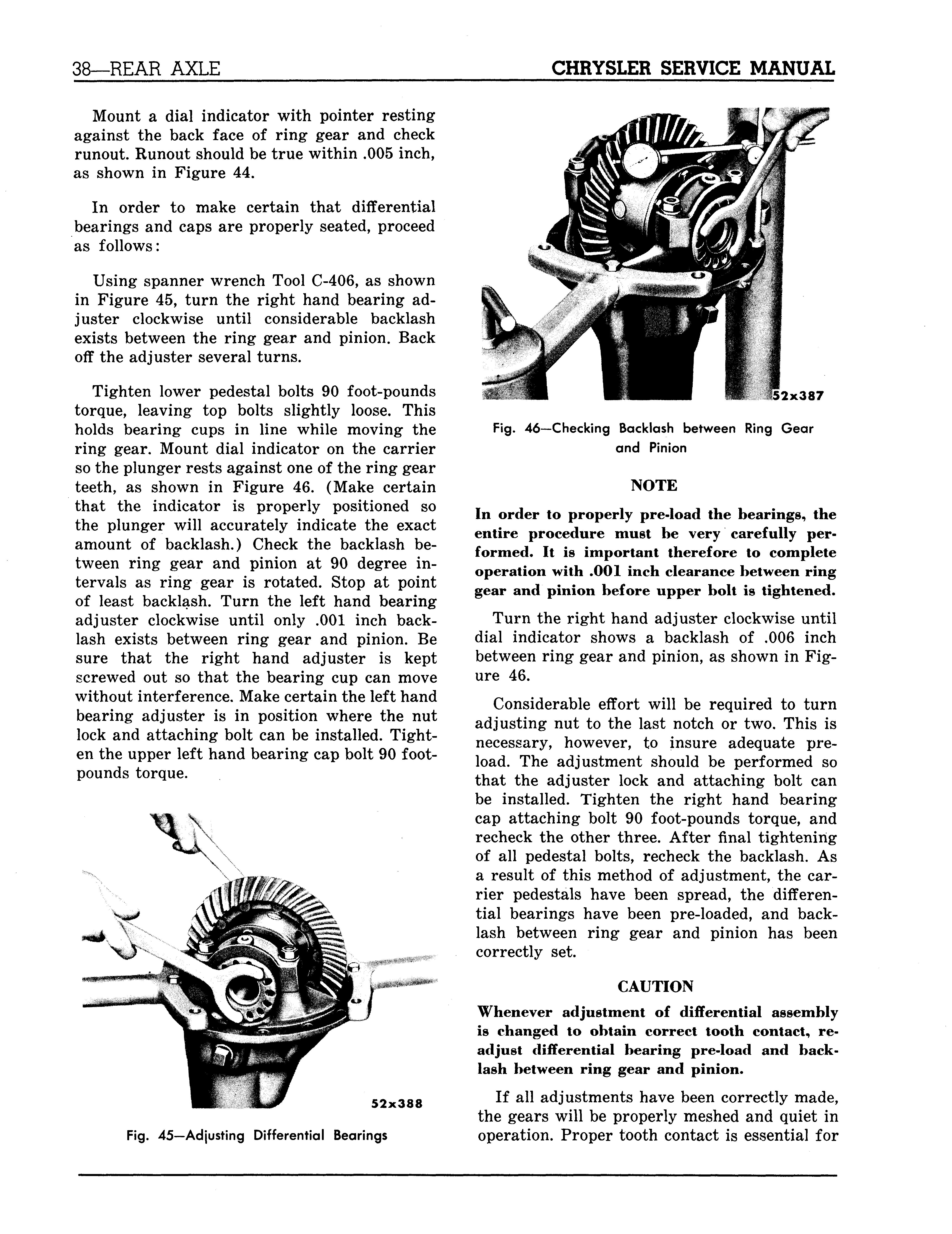
Using spanner wrench Tool C-406, as shown in Figure 45, turn the right hand bearing adjuster clockwise until considerable backlash exists between the ring gear and pinion. Back off the adjuster several turns.
Tighten lower pedestal bolts 90 foot-pounds torque, leaving top bolts slightly loose. This holds bearing cups in line while moving the ring gear. Mount dial indicator on the carrier so the plunger rests against one of the ring gear teeth, as shown in Figure 46. (Make certain that the indicator is properly positioned so the plunger will accurately indicate the exact amount of backlash.) Check the backlash between ring gear and pinion at 90 degree intervals as ring gear is rotated. Stop at point of least backlash. Turn the left hand bearing adjuster clockwise until only .001 inch backlash exists between ring gear and pinion. Be sure that the right hand adjuster is kept screwed out so that the bearing cup can move without interference. Make certain the left hand bearing adjuster is in position where the nut lock and attaching bolt can be installed. Tighten the upper left hand bearing cap bolt 90 footpounds torque.
52x388
Fig. 45—Adjusting Differential Bearings
2x387
Fig. 46—Checking Backlash between Ring Gear and Pinion
NOTE In order to properly pre-load the bearings, the entire procedure must be very carefully performed. It is important therefore to complete operation with .001 inch clearance between ring gear and pinion before upper bolt is tightened.
Turn the right hand adjuster clockwise until dial indicator shows a backlash of .006 inch between ring gear and pinion, as shown in Figure 46.
Considerable effort will be required to turn adjusting nut to the last notch or two. This is necessary, however, to insure adequate preload. The adjustment should be performed so that the adjuster lock and attaching bolt can be installed. Tighten the right hand bearing cap attaching bolt 90 foot-pounds torque, and recheck the other three. After final tightening of all pedestal bolts, recheck the backlash. As a result of this method of adjustment, the carrier pedestals have been spread, the differential bearings have been pre-loaded, and backlash between ring gear and pinion has been correctly set.
CAUTION Whenever adjustment of differential assembly is changed to obtain correct tooth contact, readjust differential bearing pre-load and backlash between ring gear and pinion.
If all adjustments have been correctly made, the gears will be properly meshed and quiet in operation. Proper tooth contact is essential for
46x255
Fig. 47—Applying Red Lead to Gear Teeth
quiet gear operation and long life. It is necessary, therefore, that the tooth contact be checked with gear marking compound before differential carrier assembly is installed in axle housing.
19. GEAR ADJUSTMENT FOR CORRECT
TOOTH CONTACT Check tooth contact by means of gear marking compound applied to drive gear teeth, as shown in Figure 47. Apply load against back face of the drive gear with a round bar as the drive pinion is rotated. This leaves a bare area the size, shape and location of contact.
If improper tooth contact is evident, as indicated by Figures 48 and 49, the pinion should be adjusted either forward or backward, maintaining the backlash within specified limits until correct tooth contact, as shown in Figure 47, is obtained.
With adjustments properly made, correct tooth contact, as shown in Figure 50, will re-

Fig. 49—Heavy Flank Contact
suit. Notice that the contact pattern is well centered on the drive and coast sides about Vi e inch from edges of the teeth. When tooth marks are obtained by hand, they are apt to be rather small. Under an actual operating load, however, the contact area will spread out—the higher the load, the greater becomes the contact area.
Figures 48 and 49 show improper or incorrect tooth contact. To correct such conditions, readjust drive gear and pinion as follows: a. Heavy Face Contact If tooth marking is across the length of the tooth, narrow and high on the tooth face, as shown in Figure 49, the teeth will roll over or gall. This type of contact causes excessive wear and noise.
To correct heavy face contact—move the pinion in toward the center of drive gear by installing a thicker washer behind pinion. Readjust backlash.


