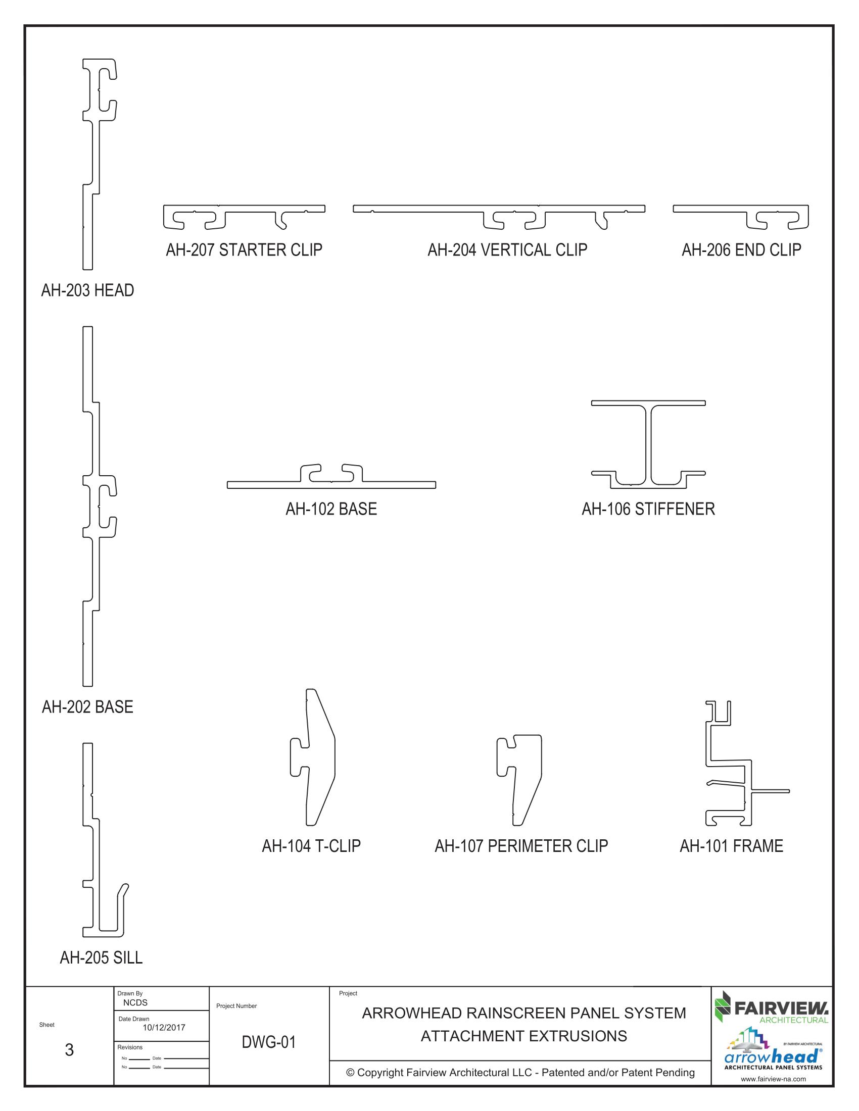


Install the AH-205 J-Sill extrusion at the bottom of the wall. Take care to ensure this extrusion is shimmed and levelled as the locations of the other base extrusions will be based on this extrusion.


Fasten the AH-202 Base extrusion to the wall. Shim as required.
PRO TIP: Use a spare piece of MCM as a spacer between the AH-202 extrusions.
Tired of reading? Access the training videos using the QR code below


Fasten the AH-203 Head extrusion to the top of the wall. Shim as required.


Attach the AH-207 Starter Clip to the extrusions on the left side of the wall. Ensure there is a clip at the top and bottom of each panel.
Tired of reading? Access the training videos using the QR code below


Attach the AH-204 Vertical Clip to the extrusions wherever two panels are side -by-side on a flat wall. Ensure that the flat side of the clip is on the left side. Ensure there is a clip at the top and bottom of each panel.

The notch on the right side of the AH-207 Starter Clip ensures that the panels only expand/move to the right.

Ensure there is a clip at the top and bottom of each panel.
Tired of reading? Access the training videos using the QR code below


FO = Frame Opening
SO = Sill Opening
Finished Panel Size = FO + 3/16”
Finished Panel Size = SO
CO = Corner Opening
PD = Panel Depth
Finished Panel Size = CO + PD + 1/16”
Sizes are for up to 10’ long panels at 1/8” in 10’ at <90° F thermal expansion
For longer panels or high temperature increases modify formula accordingly


Clips onto the AH-202 Base Extrusion if starting on any row except the bottom. If the first panel is being installed on the bottom row, this step is not necessary.

Clip the panel to the wall by sliding the AH 401 Perimeter Extrusion over the AH


the panel in place.


Tired of reading?
Access the training videos using the QR code .
If installing a panel above another panel, repeat steps 13 and 14 and slide the AH-401 over the AH-104 T-Clip instead of the AH-107 or AH-205.
Repeat steps 13 and 14
Insert reveal strips as required.


Fabricate the replacement panel and bring it on site prior to removing the panel that is to be replaced.
Create the 3-piece replacement reveal at the same time using Fairview’s CNC program.

Cover the adjacent panels with something that will protect them while the damaged panel is being removed.
Scan the code below for a video showing how to replace a panel.


1 2 3


Cut out the left, top, and right reveal strips. There is no need to cut out the bottom reveal strip.
Remove the reveal strips to be able to access the t-clips. Use the AH-110 locking tool to remove the t-clips. At this point, the damaged panel can be removed.
Scan the code below for a video showing how to replace a panel.


Square off the existing reveal so the replacement reveal can butt right up to it.

Determine the length the replacement reveal needs to be, and cut it to length. Keep the first hole approximately 2-3 inches from one end as this is where the first T-Clip will be located.
reveal slots. You may need to add a small amount of caulk to the middle of each reveal slot to hold it in place.
Scan the code below for a video showing how to replace a panel.


Take the corresponding side pieces and insert them in the right, top and left reveal slots of the replacement panel.
Slide the replacement panel over the bottom t-clips and reveal strip.
Scan the code below for a video showing how to replace a panel.


secures the replacement panel in place.

Once all the t-clips are in place, apply sealant into the middle of the groove of the replacement reveal strip center piece.

Scan the code below for a video showing how to replace a panel.


Snap the center of the replacement reveal strip into place, lining it up with the corresponding side piece.
Use the AH-133 Reveal Wheel to roll down the replacement reveals to ensure a smooth, locked in connection.

Scan the code below for a video showing how to replace a panel.

