



Ensure the panel returns are at 1” o.d. +/- 1/64”.
Route complete panels. Ensure that the grain direction is the same for all panels unless specified otherwise.
Use final panel dimensions as per the extrusions that have been installed on the wall.
Tired of reading? Access the training videos using the QR code below


Drill 5/16” diameter weep holes. These are located 8” from each end. For panels over 72” long, add an additional weep hole in the middle.

Tired of reading?
Drill 5/32” attachment holes. These are located 2” from each end and 16” on center maximum.
Access the training videos using the QR code below


countersink


If needed, minimally file the round inner corners created by the CNC’s router bit, to ensure that when the returns are folded, they create a clean crisp corner.
For the best overall appearance of a formed panel corner, use a flat file to make the 1” ends of the returns come to a point instead of square from the router. File as little as possible and as evenly as possible. This can be done at the same time as the above.
On the finished side of the panels, countersink the rivet holes so that the rivets appear flush with the surface of the return when installed.
Tired of reading? Access the training videos using the QR code below


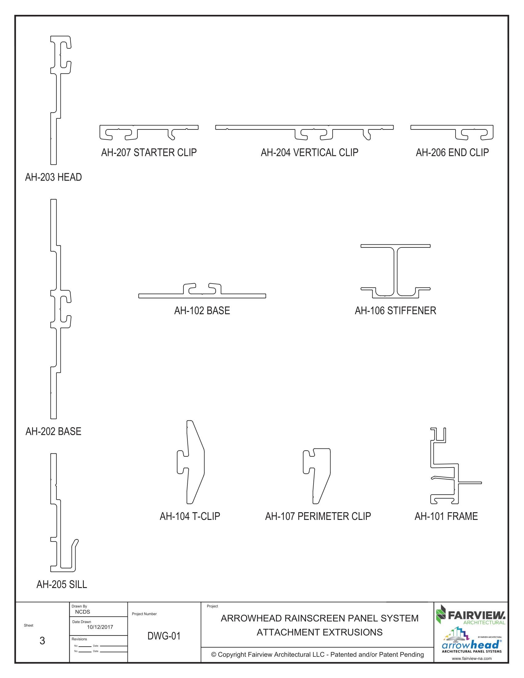
Based on the o.d. of your square or rectangular panels, determine the lengths that the AH-101 Frame Extrusions need to be cut to.
For the AAMA-509 Drained/Back Ventilated System subtract 2.75” from the o. d. of your panel for both length and width of the panel.

Tired of reading?
For the AAMA-508 Pressure Equalized System subtract 7/16” from the o.d. of your panel for both length and width of the panel. For the AH-508 system the Frame extrusions are mitered so keep your tolerances tight by using stopping devices on your saw and check dimensions frequently.
The length of the AH-106 Stiffener is normally based on the shortest dimension of the panel. Cut the Stiffener 15/8” shorter than the o.d. of that dimension.
Access the training videos using the QR code below


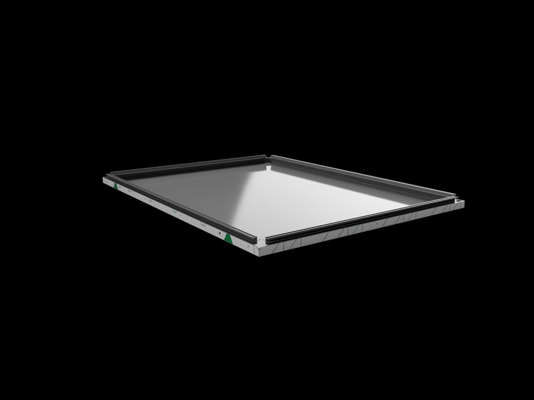
Form all 1” panel returns to 90 degrees. If there are V-grooves other than for returns, don’t bend them at this time.

Tired of reading? Access the training videos using the QR code below
Assemble the AH-101 Frame Extrusions onto the panels making sure to keep them centered. Use locking clamps similar to Radnor’s Locking Weld Clamp (9” or larger) to hold the Frame Extrusion in place. The clamps should straddle the attachment holes for easier drilling. Then rivet the frame extrusions to the panel at each of the holes drilled in step 12.


Add the AH-108 Panel Bracket into a panelcorner on top of both Frame extrusion shelves. Hold the Panel Bracket tight against one Frame but hold it about 1/16” away from the other.
Using a standard Vice Grip, hold the flush side of the Panel Bracket in place against the Frame and fasten it using a Tek screw (#8 x ½” or similar) or clinching device.
Pinch the corner together making it tight, then hold that position by using a Vice Grip on the un-fastened side so that it can’t move. Fasten using a Tek screw or clinching device. If the corner doesn’t look perfect, loosen the Vice Grip and make the corner look correct before Tek screwing or clinching.
Repeat for all corners.
Drill the 5/16” weep holes through the Frames at the locations already on the panel. Place one ½” x ½” x 1 ½” baffle over each weep hole, held in place by caulk that does not block the channel of the Frame.
Tired of reading? Access the training videos using the QR code below


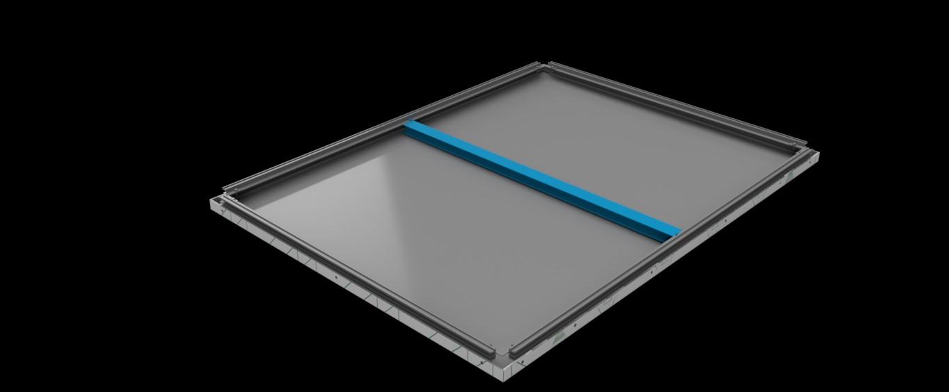
Install AH-106 Stiffeners where required.
Clean the Stiffener and panel areas where the Stiffener will be located per structural caulk instructions.
Twist the Stiffener(s) under the back shelves of both the Frames in its location.
Ensure that the panel’s outside dimensions are correct, then Tek screw (#8 x ½” or similar) or clinch the Frame to the Stiffener once on each side and in opposite corners of each other.
Add structural caulk and tool in both sides of the Stiffener per manufacturer instructions. NOTE: For panels made from sheet (not MCM) that are to be post painted, do not perform step “d” until after painting because the caulk can burn up in the high temperature ovens causing various hazards and problems.
Tired of reading? Access the training videos using the QR code below


Referring to step 17 “for V-grooves other than for returns”, such as a building’s corner panel, now is a good time to fold them into shape.
If you want, you may use the AH-108 Panel Brackets to place behind the frames in the corner to help hold the panel close to 90 degrees.
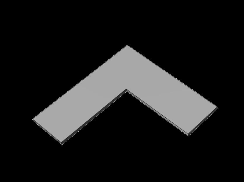
Place the AH-109 Corner Bracket onto the shelves of the Frames.
Using 2 standard Vice Grips hold both ends of the Corner Bracket to the Frame shelves with the panel formed to 90 degrees.
Tek screw or clinch the Panel Brackets in all locations to permanently hold that shape.
If the corner panel’s length is longer than 6” in either direction, consider using a Panel Brace in the middle of the corner that will be held in position by strips of double sided tape and structural caulk. This will help prevent the panel from getting bent and damaged before placing the panel on the building. Panel braces are often 4” x 4” extruded angles from .125” aluminum that are 6” long.
For deeper panel system depths make the Frame taller: (TEST THE PROCEDURE BELOW BEFORE BEGINNING PRODUCTION TO ENSURE THAT THE STRIPS ARE THE PROPER LENGTH.)
Determine the system depth you need.
Cut 4mm MCM into strips consistently to the correct width (scratches and similar defects OK since these will not be seen).
Cut these strips to the length of the Frames and for all of the Frames on each panel (minus about ¼” in length for AH-508 Systems).
Fully insert the strips into the 4mm wide channel at the top of the Frames. Your Frames are now taller and ready for fabrication and assembly.
Start from the beginning and follow the complete instructions above but based on the new panel system depth.
At assembly, ensure that the panel return is at the proper location on the Frame before permanently fastening.
Tired of reading? Access the training videos using the QR code below

(NOTE: If using .125” in place of 4mm, install the strips, then hit the back of the 4mm channel on the backside of the Frame to close the distance of the channel to .125”.)
Again, referring to ASSEMBLY step #1 “for V-grooves other than for returns”, such as a building’s corner panel that is NOT 90 degrees, use 1/16” thick brake shapes in place of the AH-108 Panel Bracket and the AH-109 Corner Bracket. Use 1/8” aluminum brake shapes for the panel brace if required. All will be at the correct angle required.
