A. C. Aydin, A. Ardalani, M. Maali, M. Kiliç: Numeric modelling of innovative semi-rigid connections under cyclic loading
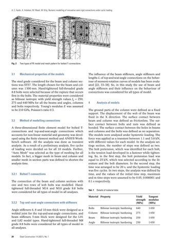
Fig. 2
Two types of FE model and mesh pattern for bolted T-connections
3.1
Mechanical properties of the models
The steel grade considered for the beam and column sections was ST37. The length chosen for the beam and column was 1 500 mm. Hand-tightened full-threaded grade 8.8 bolts were selected because of the rupture that occurs first in the bolts. The material properties were considered as bilinear isotropic with yield strength values fy = 250, 275 and 640 MPa for all the beams and angles, columns and bolts respectively. Young’s modulus E was assumed to be 210 GPa, Poisson’s ratio 0.3.
3.2
Method of modelling connections
A three-dimensional finite element model for bolted Tconnections and top-and-seat-angle connections which accounts for non-linear material and geometry was developed using the finite element method and ANSYS Workbench software. All the analysis was done as transient analysis. As a result of a preliminary analysis, five cycles of loading were decided on for all 10 models. Further, “Auto Mesh” was selected as the type of meshing for all models. In fact, a bigger mesh in beam and column and smaller mesh in section parts was defined to shorten the analysis time.
3.2.1 Bolted T-connections The connection of the beam and column sections with one and two rows of web bolts was modelled. Handtightened full-threaded M14 and M10 grade 8.8 bolts were considered for all types of model in all analyses.
The influence of the beam stiffeners, angle stiffeners and lengths L of top-and-seat-angle connections on the behaviour of moment-rotation curves of models has been evaluated [22, 33–38]. So, in this study the use of beam and angle stiffeners and their influence on the behaviour of connections was considered for all types of model.
4
Analysis of models
The ground parts of the column were defined as a fixed support. The displacement of the web of the beam was fixed in the X direction. The surface contact between beam and column was defined as frictionless. The surface contact between bolts and nuts was defined as bonded. The surface contact between the holes in beams and columns and the bolts was defined as no separation. The models were analysed under hysteretic loading. The force was applied as a transient between 1.1 and 3.8 kN, with different values for each model. In the analysis settings section, the number of steps was defined as two. The bolt pretension, which was identified for each bolt, is the tension load developed in a fastener while tightening. So, in the first step, the bolt pretension load was equal to 25 kN, which was selected according to the literature and the bolt diameters. In the second step, the time was arranged to be 20 s, and the hysteretic loading was five cycles. In two steps, the analysis was defined by time, and the values of the initial time step, maximum and m time steps were assumed to be 0.05, 0.000001 and 0.1 s respectively. Tab. 1 Details of material data
Material Property
Yield strength (MPa)
Tangent modulus (MPa)
Bolts
Bilinear isotropic hardening
640
1 450
Column
Bilinear isotropic hardening
275
1 450
Beam
Bilinear isotropic hardening
250
1 450
Angle
Bilinear isotropic hardening
250
1 450
3.2.2 Top-and-seat-angle connections with stiffeners Angle stiffeners 6, 8 and 10 mm thick were designed as a welded joint for the top-and-seat-angle connections, and beam stiffeners 5 mm thick were designed for the L91 and L82 model types. Hand-tightened full-threaded M8 grade 8.8 bolts were considered for all types of model in all analyses. 24
Steel Construction 14 (2021), No. 1
00_STCO_0121_Buch.indb 24
03.02.21 11:15


