22 minute read
Genoa San Giorgio Bridge


was also necessary for the reinforced concrete works to be carried out simultaneously in such a way as to give enough anticipation to the laying of the deck (Fig. 2).
The Fincantieri Group used the sites in Valeggio sul Mincio (VR), Castellammare di Stabia (NA) and Sestri Ponente (GE) to produce the Genoa Bridge for the construction of the metal structures the deck was made of. Only through the preliminary analysis of the potential and skills of the individual sites was it possible to focus the objective of each plant and maximise productivity.
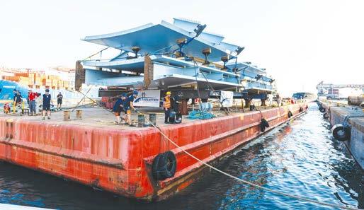
The dressing elements of the macro elements and all the upper structures such as longitudinal beams, transverse elements and profles were made, welded and checked at the production site Valeggio S/M equipped with automatic welding systems such as the T-Master, with tandem confguration, and manipulators with one and two opposing welding heads; the technologies used maximize the repeatability of the welding process, ensuring its quality. The macro elements that form the bottom of the deck were made in the shipyards of Castellammare di Stabia and Sestri Ponente with a bottom plate welded in a single solution through the use of automatic „Panel Line“ welding equipment, to then be structured with longitudinal beams and transverse stifeners. In an equally strategic way, the pier elements, structural elements of considerable constructive complexity due to the presence of heavy stresses and welds of particular difculty and size, were separated from in-line production. The decision to make the 18 pier segments as complete structural elements was fundamental to optimise construction times. After the completion of the geometric control activities and the execution of Non-Destructive Testing (NDT), the structural elements were painted with a highly durable C5 VH paint cycle in a very aggressive environment in accordance with UNI EN ISO 12994 – 2 and a decisive fnishing colour wanted by the Architectural Management of RAL Design 220 80 05 with a surface gloss of 30%. The macro elements made at the production sites of Castellammare di Stabia and Sestri Ponente were transported by barges across the Tyrrhenian Sea to the pier near the mouth of the Polcevera river (Fig. 3); once disembarked and positioned on particular multi-axle and high lift trailers, they
Fig. 3 Loading on barge of the macro blocks in Castellammare di Stabia (Naples) were transported to the construction site with big overnight transport vehicles.
The maximum width of 10 m of the macro elements was analysed in the design phase to allow the particular transport method, performed with a few spare centimetres in relation to the passage areas.
The entire metal deck has a total weight of about 17,500 tons of which about 77% was processed at Valeggio S/M. Part of this material was delivered directly to the shipyard in Val Polcevera while 30% was transported to the Naval production sites where the structural elements were welded to the metal sheets of the previously prepared keeled bottom. The construction and shipment of the 262 macro segments based on the management programme prepared and monitored daily was essential for respecting the project’s challenging implementation deadlines.
4 Assembly and monitoring of the works
The spans were assembled starting from the calendered bottoms placed on provisional works on which each segment was progressively based with the diaphragms, main beams, side panels and, fnally, the panels. The upper main beams were welded to the lower beams along with the bottom of the segment by means of longitudinal corner bead welding. The segments were subsequently welded together at full penetration before being moved to be raised. The joint preparation, preheating and welding control activities were supervised by the welding coordinators and checked upon completion of the same in accordance with the inspection plan with visual, magnetic and ultrasound methods. All the personnel used for welding activities on the ground and at height were in possession of licenses issued by the accredited third party Accredia.
The upper transverse elements and the diaphragms were assembled by means of bolted joints using HRC bolts. This particular bolt allows the reduction of the tightening control times required by the standards to ensure the successful application of the tightening torque.
All the movements of the segments and the macro elements of the spans were carried out with SPMT (Self Propelled Modular Transport) trolleys, in modules with 4 or 6 axes that can be assembled according to transport needs. The system ofered great versatility in displacements and made it possible to move from the smallest macro-segments, weighing about ten tons, up to 100 m fully assembled spans of 1,800 tons (Fig. 4).
The construction site faced extremely adverse environmental conditions, with almost 100 days of hydrogeological weather alert from September 2019 to June 2020 with whole days of intense rain or strong wind. In addition to this, in a paroxysm of complications, the Covid19 pandemic exploded in Italy. The frst strong containment countermeasures that almost stopped the nation were es-
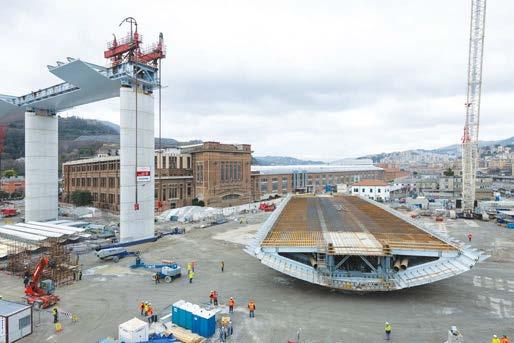
Fig. 4 Movement with SPMT trolleys of a 100 m span
tablished at the most important moment of the assembly, when the lifting above the river was in progress and the lifting of the span above the railway was imminent. To the professional tension due to the importance of the phase to be overcome, the physical fatigue of the previous months, the stress caused by the incessant media attention given to the construction site, human concern for health reasons was added. It was at this moment that all the people involved gave the greatest sign of strength and cohesion, capable of reshaping the way of working to ensure common safety, managing to maintain the same very high pace that had been sustained up to that moment, with the collective goal of completing the work.
5 Movement of the decks
The lifting was divided into two types, with cranes and lifts with strand jacks. A pair of tandem cranes were used for the 50 m spans. A single heavy-duty crane was used for the shoulder lifts (SA-P1, P1-P2, P17-P18 and P18-SB) and ramp lifts. Strand jacks were used for the 100 m spans and the two key lifts of P2-P3 and P11-P12 (Fig. 5).
The tandem lift technique involved the assembly of the segments in two main confgurations.


Fig. 6 50m spam ready for tandem lifting
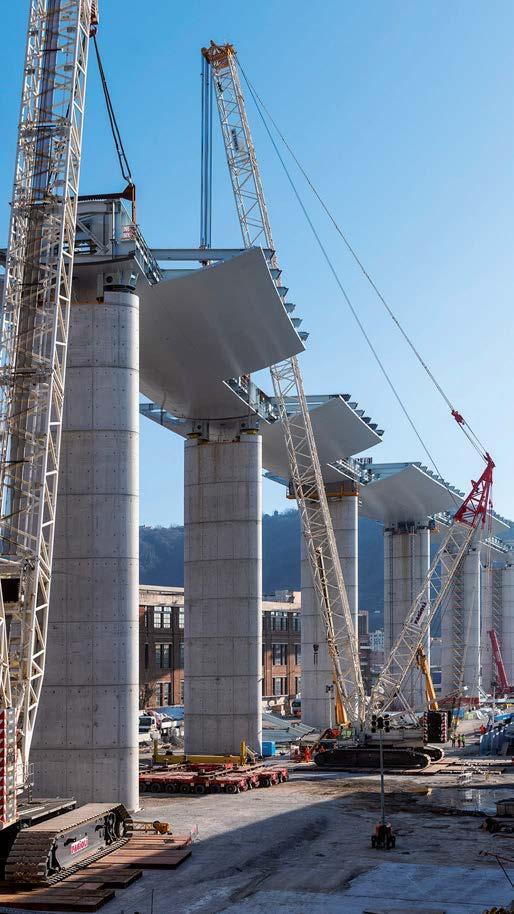
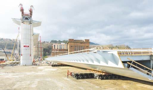
Fig. 8 Movement with SPMT of a 100 m span and lifting equipment with strand jack Fig. 9 Lifting phase of the 100m span between piers 8 and 9

– The two initial lifts (P5-P6 and P14-P15) were made with a macro element consisting of the two central pier segments and the central part of the span, to create a self-supporting structure; – The subsequent lifts were carried out by moving the entire span and the subsequent stack of stone, relying on the previous element moved using special brackets.
The spans thus confgured raised in tandem had a weight of between 400 and 600 tons (Fig. 6).
The lifting sub-contractors made a total of fve crawler cranes available, all operating simultaneously between February and March 2020:
– Two Terex-Demag CC2800, maximum capacity 600 tons – A Terex-Demag CC3800, maximum capacity 650 tons – Two Terex-Demag CC6800, maximum capacity 1250 tons
The tandem lifting took place by coupling a CC6800 with a CC2800 (or alternatively the CC3800) confgured with 78 m arms, choosing the gripping points to maximise the efciency of crane capacity (Fig. 7).
It was not possible to intervene as described above for the end areas of the deck, due to the impossibility of creating spaces close to the shoulders, due to the interference of persistent motorway trafc and the complex orography with steep slopes. For these sections, the single lift technique was adopted with large-capacity cranes and the use of temporary towers to break down the spans into subsegments of a weight suitable for the crane’s capacity compatible with the large outreaches required.
For these lifts (SA-P1, P1-P2, P17-P18 and P18-SB) and the ramp lifts, a single CC6800 was used with a change of boom confguration at 114 m for the west side, 102 m for the eastern side and 78 m for the ramp.
The 100 m spans and the two 50 m closing spans (P2-P3 and P11-P12) were instead completely assembled on the ground, including pre-slabs, slow reinforcement of the slab and system elements inside the deck, arriving at a maximum total weight of approximately 1,800 tons. Due to the considerable weights involved for lifting and to resolve interference with the substructures, it was necessary to resort to the lifting technique using strand jacks (Fig. 8).
For each lift, four pairs of cable recovery jacks were used connected to the deck to be lifted with dedicated eyebolts and stifeners.
To raise the spans from 100 m from the side of the deck at high altitude, a system of lifting beams and eyebolts made it possible to balance the lifting actions, while on the opposite side this function was performed by a block of ballasts. Each jack has a limit capacity of 1,400 tons and a cable recovery stroke of 450 mm, which in practice translates into a deck lifting speed of about 7 m/h (Fig. 9).
Before lifting each of these spans, it was necessary to position the stack segment on the next alignment to install the strand jacks and the adjustment system for inserting the spans. Structures were installed under the segments of P9, P10 and P11 which made it possible, thanks to pairs of jacks positioned along the three main axes, to move the pier segment in order to precisely align the spans at a height. The raised spans, with an overall length of 94 m, were inserted into an opening just 5 cm wider. This precision was achieved thanks to the cutting of the ends of the spans on the ground according to the angle of the edges of the piers, surveyed topographically, aided by a regulation
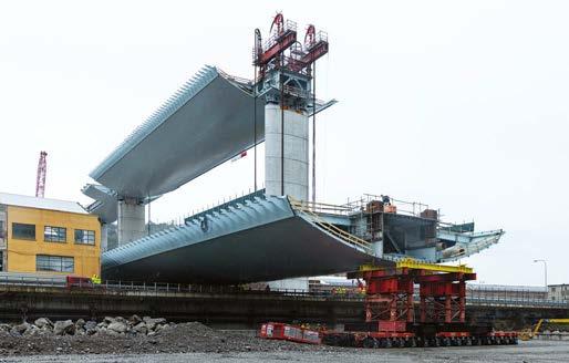
Fig. 10 Taking charge of the span with SPMT trolleys in the Polcevera riverbed
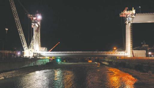
Fig. 11 100 m span above the Polcevera river ready for lifting

Fig. 12 Lifting connection of the coupling structure to the bridge
system that closed the opening once the joints were correctly aligned, ensuring the millimetre tolerances necessary for making joints with full penetration at a height.
For the Polcevera and railway crossing spans it was necessary to carry out preliminary lifting due to the diferences in height between the areas where the SPMTs had to move and due to the height of the obstacles. (Via 30 Giugno, Via Perlasca and the railway grounds)
This lift (in other words jack-up) raised the decks with respect to the support height for the assembly by about 1.50 m for movement onto the Polcevera and about 3.00 m for positioning above the railway, requiring the use of special temporary structures to be interposed between the deck and SPMT trolleys (Figs. 10, 11).
The frst lift was carried out on 1 October 2019 in the Ponente part of the construction site, while the frst lift in the Levante part of the construction site was realised on 15 December 2019.
On 28 April 2020, with the key closure of the P11-P12 span, the two banks of the Val Polcevera were reunited. The lifting operations were defnitively concluded with the positioning of the last span of the ramp on 29 May 2020, just 333 days after the arrival of the frst structural element on site (Fig. 12).
6 Final activities and testing
Once the deck at height was completed, with the assembly of the side panels, panels, the installation of the slabs and the mild reinforcement, before casting the slab, the weighing of the deck and the lowering up to the design height remained to be performed.
The spans were laid on the piers 265 mm higher than the design height, to allow the weighing of the deck and the application of the design constraints, as well as to have adequate ease in the assembly of the provisional and fnal supports.
The fnal supports of the deck, double-surface pendulum isolators, could not be directly loaded during the transitional assembly phase since they were not designed for the application of movements and rotations necessary only during the spans’ laying and alignment phase.
When the operations at height were fnished, the deck was placed accurately on the piers, sensitive due to their slenderness to excessive decentralization that thermal variations could result in during assembly at height. For this operation, provisional elements were made which encapsulated, on each pier, two pairs of vertical jacks and a pair of horizontal jacks, resting on a sliding guide made up stainless steel-tefon which allowed the required longitudinal and vertical displacements to be obtained.
The jacks, equipped with precision pressure gauges, therefore made it possible to measure the constraint reactions and to adjust the measured value with small constraints until it corresponded to the theoretical values. At the end of the weighing, the bridge was lowered step by step to the desired height and then grouting of the supports was caried out. The structural continuity between the deck, support and pier, was therefore completed, a situation that efectively sanctioned the conclusion of the assembly of the metal deck.

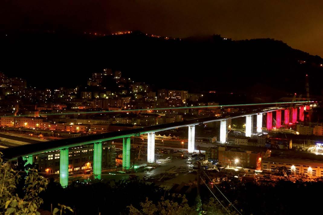
Fig. 13 General view of Ponte San Giorgio The casting of the concrete slab, laying of the road surface and dressing it with safety barriers, photovoltaic panels and protective windows, as well as the installation of robotic means for the control and cleaning of the deck, allowed the static and dynamic testing of the works to start.
For the dynamic testing, an operational modal analysis (OMA) was carried out with the aid of Tromino® tromographs synchronized to uniaxial velocimeters suitably positioned on the spans. Thanks to the measurement of the vibrations induced by natural microtremors (wind, trafc, nearby production activities) it was possible to check the correspondence of the real vibration of the structure with the theoretical vibration. A further dynamic type test to verify any horizontal displacements on the supports or piers was performed with a braking test with 8 fully loaded trucks that travelled over the deck at a speed of 50 km/h, at P9, which braked synchronously to a stop. The test did not show any appreciable displacement of the transducers positioned on the supports.
A total of 56 5-axle trucks (tractor plus trailer) loaded up to 46 tons and 4 SPMT modules loaded to 130 tons were used for the static testing, for a total of 12 tests (4 with negative moment on Piers 4, 10, 15 and pier 3 of the ramp, 7 with positive moment on spans SPA-P1, P3-P4, P4-P5, P9-P10, P14-P15, P2-P3 of the ramp and a test on
the coupling between the ramp and main axis), during which 100 % of the stress test required by the design was reached. The single typical positive moment test required 24 vehicles, for a total of more than 1,000 tons, while for the negative moment test of pier 10 required 44 vehicles spread over the two adjacent spans. The SPMTs were used on the ramp spans where the reduced width of the road platform would have allowed the positioning of an insufcient number of trucks to reach the stress level to be verifed. The measured lowering corresponded fully to the expected values, of about 2.00 cm defection in the 50 m Spans and 8.00 cm for the 100 m spans.
For the testing and monitoring activities, the range of instruments used was completed by the strain gauge sensors installed on the metal carpentry in the middle of spans P3-P4 and P9-P10 and piers 4, 10 and 15 and the strain gauge bars embedded in the concrete of the slab of the above-mentioned piers and on pier 3 of the ramp. This set of sensors made it possible to verify, in real time, the evolution of the stress state of the section while the tests progressed and will continue to measure the deformations of the deck during the life-cycle of the structure, allowing constant monitoring of the structure over time in a simple and reliable manner (Figs. 13, 14). An iconic project managed by leading companies in the sector that have managed to continuously supply a construction site that managed to meet the deadlines promised to the City of Genoa and above all to its citizens. A success achieved only with very detailed planning of the activities and thanks to the work and skills of people who felt as if they were an integral part of a project characterised by efciency, safety and quality. The bridge, in addition to healing a wound in the city of Genoa, mapped out a method with which to deal with the execution of the large-scale works in Italy, Competence – Efciency – Planning.
Project team
Architect: Arch. Renzo Piano Steel structural engineer: Italferr S.p.A. Project supervisor: Rina Consulting S.p.A. Main contractor: Pergenova S.C.p.A Steel main fabricator: Fincantieri Infrastructure S.p.A. Steel sub fabricator: Fincantieri S.p.A. Lifting sub contractor: Fagioli S.p.A. Lifting sub contractor: Vernazza Autogru S.r.l. Civil contractor: Webuild S.p.A.
Authors
Eng. Gioacchino Sarcina (corresponding author) Gioacchino.Sarcina@fncantieri-infrastructure.it Fincantieri Infrastructure S.p.A. Via del Lavoro, 1 37067 Valeggio sul Mincio, Verona, Italy
Eng. Siro Dal Zotto Siro.DalZotto@fncantieri-infrastructure.it Fincantieri Infrastructure S.p.A. Via del Lavoro, 1 37067 Valeggio sul Mincio, Verona, Italy
Eng. Francesco Poltronieri Francesco.Poltronieri@fncantieri-infrastructure.it Fincantieri Infrastructure S.p.A. Via del Lavoro, 1 37067 Valeggio sul Mincio, Verona, Italy
Eng. Marco Raccagni Marco.Raccagni@fncantieri-infrastructure.it Fincantieri Infrastructure S.p.A. Via del Lavoro, 1 37067 Valeggio sul Mincio, Verona, Italy
Eng. Lorenzo Sartori Lorenzo.Sartori@fncantieri-infrastructure.it Fincantieri Infrastructure S.p.A. Via del Lavoro, 1 37067 Valeggio sul Mincio, Verona, Italy Vito Cardella Vito.Cardella@fncantieri-infrastructure.it Fincantieri Infrastructure S.p.A. Via del Lavoro, 1 37067 Valeggio sul Mincio, Verona, Italy
Andrea Morbin Andrea.Morbin@fncantieri-infrastructure.it Fincantieri Infrastructure S.p.A. Via del Lavoro, 1 37067 Valeggio sul Mincio, Verona, Italy
How to Cite this Paper
Sarcina, G.; Poltronieri, F.; Raccagni, M.; Dal Zotto, S.; Sartori, L.; Cardella, V.; Morbin, A. (2021) Genoa San Giorgio Bridge – The realization of an iconic artifact. Steel Construction 14, No. 1, pp. 14–21. https://doi.org/10.1002/stco.202000061
Numeric modelling of innovative semi-rigid connections under cyclic loading
This paper presents the analytical results of six steel bolted T-connection models and four steel bolted beam-to-column connection models with top and seat angles. This study was undertaken to analyse the infuence of bolted T-connections instead of welded connections and the infuence of angles with and without stiffeners on the behaviour of the beam-to-column connections under hysteretic loading. The aim was to compare the energy dissipation of different connections with each other. The energy dissipation characteristics are obtained from the main characteristics of moment-rotation hysteresis curves. This study shows that the energy dissipation decreased by about 2–29 % and 2–13 % for bolted T-connection and top-andseat-angle connection models respectively after switching from one cycle to another in fve hysteretic loadings.
Keywords semi-rigid connections; T-connections; top-and-seat-angle connections; beam stiffeners; moment-rotation; energy dissipation
1 Introduction
It is known that the behaviour of beam-column joints in steel frames plays a noticeable role in presenting the actual behaviour of structures [1]. Further, the moment-rotation curves, which are the visual expressions of the actual behaviour of beam-to-column connections, have been discovered in diferent experiments [2]. Although carrying out experimental tests is too expensive and unsuitable for everyday practice tests, the accurate behaviour of beamto-column connections can be obtained through experimental tests, and these are usually used for research purposes only [3, 4]. These experiments have been conducted since 1917, when the frst experimental testing of the rigidity of steel frame joints was carried out at the University of Illinois by Wilson and Moore [5].
The four most important databases from experiments are:
a. Goverdhan database [6], which was developed in 1984, containing the results of 230 tests from the USA. b. Nethercot, the frst European database [7, 8], developed in 1985, which contains results from more than 70 experiments on steel connections. c. Steel connection database [9, 11]. This database collected the results of experimental tests carried out from 1936 to 1986 by Kishi and Chen [12] from all over the world. They followed the work of Goverdhan in the
USA and they studied the results of 303 tests. Later, in 1995, 46 additional experimental tests on steel frame
joints were conducted by Abdalla and Chen [13], and their results were added to this database. d. SERICON databank [14, 15], which contains composite combinations and was developed by Arbed Recherches and Aachen University [16]. Afterwards,
SERICON II was extended in 1998 by Cruz et al. [17].
By using these databases, the classifcation of mathematical models experimentally tested from 1958 to 1990 is limited to the following seven types of steel beam-to-column connection:
i. Single web angle ii. Double web angle iii. Header plate iv. Top and seat angles v. End plate without column stifeners vi. End plate with column stifeners vii. T-stub
However, there are many diferent types of beam-to-column connection that are not identifed in these databases.
Owing to the important role of beam-column joints in steel structures, the use of bolted connections known as semi-rigid connections is suggested for steel frameworks in structures. The semi-rigid joints of steel structures play the most important role in the resistance, rigidity, rotation capacity and energy dissipative features. Rigid connections, which are frameworks with welded joints, are too expensive and involve difcult assembly conditions, whereas fexible connections have neither a sufcient stifness nor the necessary resistance to static and dynamic loads [1], see Fig. 1.
The common behaviour of the beam-column connections is categorized as rigid and pinned to make frame analysis simpler. Additionally, investigations have shown that in steel structures the actual behaviour of the majority of connections is neither perfectly rigid nor perfectly hinged, so they behave as “semi-rigid” connections. Owing to the unique properties of moment-rotation relationships in semi-rigid connections, it is easy to observe the strength, stifness and rotation capacity from the moment-rotation curve.
Many diferent experimental tests on beam-to-column connections of steel frameworks have been examined in recent years. The study of the diferent characteristics of semi-rigid connections was excluded by many research-
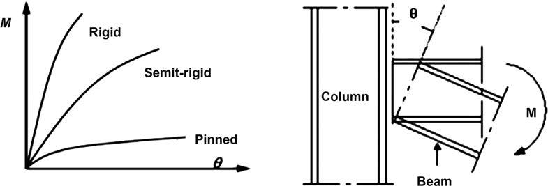
Fig. 1 Rotational deformation of semi-rigid connections
ers, including the work of Astaneh et al. [18], who investigated the hysteretic behaviour of steel double angle connections under severe cyclic seismic loading and examined six diferent connections in which angles were bolted to the column fange using A325 bolts and welded to the beam web. Azizinamini and Radziminski [19] investigated the static and cyclic behaviour of top and seat fange angles and double web angles in semi-rigid steel beam-to-column connections. Chen and Lui [20] investigated the non-linear and not easily resolvable structure for the behaviour of semi-rigid connections. On the other hand, moment-rotation curves are necessary for presenting the actual behaviour of connections. Further, the transformation of moment from beam to column is achieved through a moment connection such as a fush end-plate connection and stifened or unstifened extended end-plate connections [21]. Shi et al. [22], by carrying out experimental tests on and a theoretical analysis of stifened extended end-plate connections, were able to ascertain the moment-rotation behaviour of these connections. Actually, they were able to control local buckling and increase shear capacity in a beam web by attaching stifeners generally to the beam’s web or fanges. Although there has been no investigation of the use of a fat stifener that ftted onto the angles in beam-to-column joints either in Eurocode 3 or in the literature [23], Shi et al. [22] were able to identify an adequate moment of inertia to control deformations of planes. Maali et al. [24] investigated the infuence of angles and beams with stifeners on the behaviour of beamto-column connections. The results were obtained from experimental tests on 20 full-scale specimens of steel bolted connections with top and seat angles and beam stifeners under static loading. As a result, by increasing the thickness of the stifener beam and the length L of the top-and-seat-angle connection, the maximum bending moment, the bending moment capacity and the stifness increased. However, the maximum bending moment, the bending moment capacity and the stifness were reduced by increasing the thickness of the stifener angles. In addition, by increasing the thickness of the stifener beam and stifener angles, the energy dissipation also increased [25–37].
The aim of the present work is to analyse the behaviour of two types of semi-rigid beam-to-column connections under hysteretic loadings, which included an investigation of the behaviour of bolted T-connections, the infuence of the use of stifeners and the change of length L of top-and-seat-angle connections by using the ANSYS Workbench program. In bolted T-connections, the handtightened full-threaded M10 and M14 grade 8.8 bolts were tested for all six models. In top-and-seat-angle connections, two diferent angle lengths and three diferent stifener thicknesses were considered, and these connections also used the hand-tightened full-threaded M8 grade 8.8 bolts. The moment-rotation curves were obtained to identify the properties of the connections analysed, such as rotation capacity, maximum moment and energy dissipation.
2 Semi-rigid connections
The common behaviour of the beam-column connections is categorized as rigid and hinged to make frame analysis simpler. Furthermore, the relevant literature has shown that the majors of the connections are as “semi-rigid” connections, and the moment-rotation behavior is a proposed way to observe strength, stifness and rotation capacity, etc.
3 Description of the models
This article presents the results of two groups of beam-tocolumn connections. The frst group contains six fullscale models of steel bolted connections in the form of bolted T-connections, labelled as B240-T300-2-14, B240T300-1-14, B240-T270-2-14, B240-T240-1-14, B160T140-2-10 and B160-T200-1-10 (B = beam section, T = column section, the ordinal number of rows of bolts in the beam web and the diameter of bolts respectively). As a second group, four models were chosen for beam-tocolumn connections with top and seat angles, which are labelled similarly as L91-tp6-BS5 (1), L91-tp6-BS5 (2), L82-tp8, and L82-tp10. The frst and second groups of 10 models were created and tested for hysteretic loading, numerically. As a result of simulations, the hysteretic loading, the loading times is decided to get lasted after fve cycles. The details of the two types of model are shown in Fig. 2 and Fig. 3.