24 minute read
Numeric modelling of innovative semi-rigid connections under cyclic loading


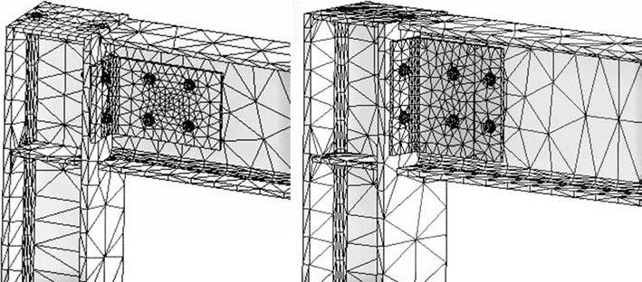
Fig. 2 Two types of FE model and mesh pattern for bolted T-connections
3.1 Mechanical properties of the models
The steel grade considered for the beam and column sections was ST37. The length chosen for the beam and column was 1500 mm. Hand-tightened full-threaded grade 8.8 bolts were selected because of the rupture that occurs frst in the bolts. The material properties were considered as bilinear isotropic with yield strength values fy = 250, 275 and 640 MPa for all the beams and angles, columns and bolts respectively. Young’s modulus E was assumed to be 210 GPa, Poisson’s ratio 0.3.
3.2 Method of modelling connections
A three-dimensional fnite element model for bolted Tconnections and top-and-seat-angle connections which accounts for non-linear material and geometry was developed using the fnite element method and ANSYS Workbench software. All the analysis was done as transient analysis. As a result of a preliminary analysis, fve cycles of loading were decided on for all 10 models. Further, “Auto Mesh” was selected as the type of meshing for all models. In fact, a bigger mesh in beam and column and smaller mesh in section parts was defned to shorten the analysis time.
3.2.1 Bolted T-connections
The connection of the beam and column sections with one and two rows of web bolts was modelled. Handtightened full-threaded M14 and M10 grade 8.8 bolts were considered for all types of model in all analyses.
Angle stifeners 6, 8 and 10 mm thick were designed as a welded joint for the top-and-seat-angle connections, and beam stifeners 5 mm thick were designed for the L91 and L82 model types. Hand-tightened full-threaded M8 grade 8.8 bolts were considered for all types of model in all analyses. The infuence of the beam stifeners, angle stifeners and lengths L of top-and-seat-angle connections on the behaviour of moment-rotation curves of models has been evaluated [22, 33–38]. So, in this study the use of beam and angle stifeners and their infuence on the behaviour of connections was considered for all types of model.
4 Analysis of models
The ground parts of the column were defned as a fxed support. The displacement of the web of the beam was fxed in the X direction. The surface contact between beam and column was defned as frictionless. The surface contact between bolts and nuts was defned as bonded. The surface contact between the holes in beams and columns and the bolts was defned as no separation. The models were analysed under hysteretic loading. The force was applied as a transient between 1.1 and 3.8 kN, with diferent values for each model. In the analysis settings section, the number of steps was defned as two. The bolt pretension, which was identifed for each bolt, is the tension load developed in a fastener while tightening. So, in the frst step, the bolt pretension load was equal to 25 kN, which was selected according to the literature and the bolt diameters. In the second step, the time was arranged to be 20 s, and the hysteretic loading was fve cycles. In two steps, the analysis was defned by time, and the values of the initial time step, maximum and m time steps were assumed to be 0.05, 0.000001 and 0.1 s respectively.
Tab. 1 Details of material data
Material Property Yield strength (MPa) Tangent modulus (MPa)
Bolts Bilinear isotropic hardening 640 1450 Column Bilinear isotropic hardening 275 1450 Beam Bilinear isotropic hardening 250 1450 Angle Bilinear isotropic hardening 250 1450
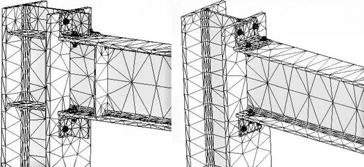
Fig. 3 Two types of FE model and mesh pattern for top-and-seat-angle connections
Directional deformation, maximum shear stress and equivalent stress (von Mises) are important properties when fnding the actual result for each model. By using these properties, it was possible to derive the force-deformation and the moment-rotation hysteresis curves. As a result of hysteretic loading, by completing the elastic deformations, plastic deformations were generated which caused energy dissipation in the models. Further, the value of this energy dissipation was calculated from the area under the moment-rotation hysteresis curve.
5 Analysis results
The force-deformation curve that explains the relationship between the applied force P and the corresponding deformation D between the members of connections was derived from the deformation of the specifed node on the end of a beam afected by the load that was applied to this point. On the other hand, the M-q curve describes the relationship between the applied moment M and the corresponding rotation q between the members of connections. Essentially, the bending moment is derived by multiplying the distance between the load application points L and the applied force P at the beam’s end point:
(1)
Further, the rotational deformation of the connection q is derived from the displacement D that occurs between the members:
(2)
M PL= (kNmm)
θ = arctan( L )∆ (degree)
5.1. Characteristics of the analyses
a. Model B240-T300-2-14(1) and B240-T270-2-14(3) bolted T-connection
The models were analysed under hysteretic loading equal to 3.65 and 3.6 kN respectively. The connections had two rows of M14 web bolts.
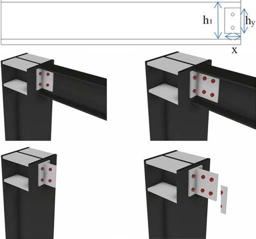
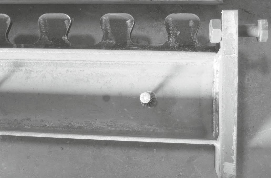
Fig. 4 Details of bolted T-connection model
b. Model B240-T300-1-14(2) and B240-T240-1-14(4) bolted T-connection
The models were analysed under vertical loading equal to 1.1 and 1.3 kN respectively. The connections had one row of M14 web bolts. c. Model B160-T140-2-10(5) and B160-T200-1-10(6) bolted T-connection
The models were analysed under hysteretic loading equal to 3.75 and 1.3 kN respectively. The connections had two rows and one row of M10 web bolts respectively.
The M-q hysteresis curves of six types of bolted T-connection are shown in Fig. 6.
The curves in Fig. 6 show that:
– The maximum moment decreased when the rows of web bolts in the connection changed from two to one. – The displacement and rotation increased when the rows of web bolts in the connection changed from two to one.
Model H =
hymin/h1 Xmax (mm)
Xmin (mm) Section thickness of T-connections Beam section Number of rows of bolts in beam web Bolt diameter (grade 8.8)
B240-T300H-Xmax-2-14 (1) 0.82 215 – IPE 300 IPE240 2 14
B240-T300H-Xmin-1-14 (2) 0.63 – 89 IPE 300 IPE240 1 14
B240-T270H-Xmin-2-14 (3) 0.82 – 89 IPE 270 IPE240 2
B240-T240H-Xmin-1-14 (4) 0.63 – 89 IPE240 IPE240 1 14
14
B160-T140H-Xmax-2-10 (5) 0.57 126 – IPE 140 IPE160 2
B160-T200H-Xmin-1-10 (6) 0.63 – 54 IPE 200 IPE160 1
* HEB160 was used as column section in all models. ** Xmin = one row of bolts, Xmax = two rows of bolts, hy = length of angle, h1 = depth of beam web
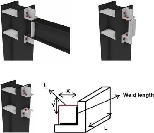
Fig. 5 Top and seat angle geometry and proposed three-dimensional semi-rigid joint 10
10 FE model
– The maximum moment decreased with a reduction in the beam thickness.
d. L91-tp6-BS5(1) and L91-tp6-BS5(2) top-and-seat-angle connection
The model was analysed under hysteretic loading equal to 3.45 and 2.95 kN respectively. The length of angles, thickness of angle stifeners and thickness of web stifener were determined as 91, 6 and 5 mm respectively. e. L82-tp8(3) and L82-tp10(4) top-and-seat-angle connection
The models were analysed for hysteretic loading equal to 3.5 and 3 kN respectively. The length of angles was chosen to be 82 mm and the thickness of angle stifeners as 8 and 10 mm respectively.
The M-q hysteresis curves of four types of top-and-seatangle connections are shown in Fig. 7.
Model Top & seat fange angle Length of angle L (mm) Stifener thickness of top & seat angle tp (mm) Web beam stifeners Stifener thickness of beam (mm) Bolt diameter (grade 8.8) Xmax ve
Ymax (mm)
L91-tp6-BS5 (1) L60x60x6 91 6 YES 5 8 5.4
L91-tp6-BS5 (2) L60x60x6 91 6 YES 5 8 5.4
L82- tp8 (3) L60x60x6 82 8 NO – 8 5.4
L82- tp10 (4) L60x60x6 82 10 NO – 8 5.4
* IPE160 was selected as the beam section and HEB as the column section in all models. ** Xmax, Ymax = width of top and seat angles FE model
The curves in Fig. 7 show that:
– The displacement increased with a reduction in the length of angles in the stifened models. – The maximum moment increased with an increase in the stifener thickness of the top and seat angle. – The moment resistance increased when using a stifener in the beam web. – The rotational capacity decreased for the stifened models. – The rotational capacity increased with an increase in the length of angles.
There are two examples of M-q graph in the frst load cycle of models, see Fig. 8 and Fig. 9.
The maximum moment values of bolted T-connections are presented in Fig. 8 and Tab. 3. The maximum moment for the B240-T300-1-14(2) model compared with the B240-T300-2-14(1) model decreased by about 70%, with the decreasing ordinal number of web bolt rows from two to one. The maximum moment for the B240-T270-2-14(3) model compared with the B240-T300-2-14(1) model decreased by about 1.37% with a change in the thickness of T-connections of IPE 300 to IPE 270 and reduction in the X value from 215 to 89 mm. The maximum moment for the B240-T240-1-14(4) model compared with the B240T300-1-14(2) model increased by about 15.38% with a change in the thickness of T-connections of IPE 300 to IPE 240 and a reduction in the X value from 215 to 89 mm. The maximum moment for the B160-T140-2-10(5) model and the B160-T200-1-10(6) model increased due to the use of a smaller bolt diameter (10 mm).
The energy dissipation values of bolted T-connections are presented in Tab. 4 and Fig. 9 for fve-cycle loading. After the elastic deformation was completed, as a result of fve hysteretic loadings, the energy dissipation values for the generated plastic deformation were 39, 23, 16, 12 and 10% respectively in the frst model, 39, 20, 16, 13 and 12% respectively in the second model, 42, 21, 15, 12 and 10% respectively in the third model, 38, 23, 16, 13 and 10% respectively in the fourth model, 49, 20, 13, 10 and 8% respectively in the ffth model, and 32, 23, 17, 15 and 13% respectively in the sixth model.
Therefore, after switching from one cycle to another, as a result of fve hysteretic loadings, the energy dissipation capacity decreased by about 16, 7, 4 and 2% respectively in the frst model, 19, 4, 3 and 1% respectively in the second model, 21, 6, 3 and 2% respectively in the third model, 15, 7, 3 and 3% respectively in the fourth model, 29, 7, 3 and 2% respectively in the ffth model, and 9, 6, 2 and 2% respectively in the sixth model.
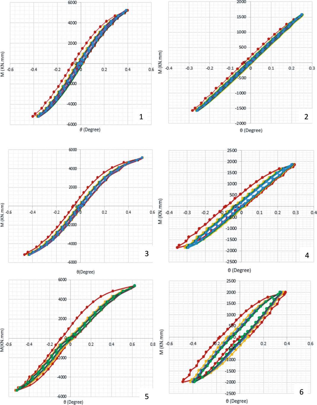
Fig. 6 Moment-rotation hysteresis curves of bolted T-connections
The energy dissipation for the B240-T300-1-14(2) model compared with the B240-T300-2-14(1) model decreased by about 87.4, 89, 87.6, 86.5 and 85.6% with a decrease in the ordinal number of web bolt rows from two to one, a reduction in the X value from 215 to 89 mm and H value from 0.82 to 0.63 mm. The energy dissipation for
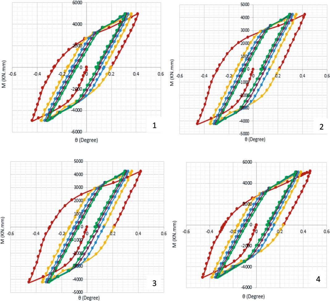
Fig. 7 Moment-rotation hysteresis curves of top-and-seat-angle connections
the B240-T270-2-14(3) model compared with the B240T300-2-14(1) model decreased by about 0.84, 16.22, 10.43, 8.65 and 8.45% with a change in the thickness of the T-connections of IPE 300 to IPE 270 and a reduction in the X value from 215 to 89 mm. The energy dissipation for the B240-T240-1-14(4) model compared with the B240-T300-1-14(2) model increased by about 70.7, 75.4, 72.6, 85.3 and 68.13% with a change in the thickness of the T-connections of IPE 300 to IPE 240. The energy dissipation for the B160-T200-1-10(6) model compared with the B160-T140-2-10(5) model decreased in the frst two cycles by about 45 and 1.99% respectively, and increased in the last three cycles by about 13.66, 19.95 and 24.18% respectively with a decrease in the ordinal number of web bolt rows from two to one, and a change in the thickness of the T-connections of IPE 140 to IPE 200. The highest value of energy dissipation as shown in Tab. 4 and Fig. 9 was found for the B160-T140-2-10(5) model in the frst cycle.
The maximum moment values of top-and-seat-angle connections are presented in Fig. 10 and Tab. 5. The maximum moment for the L91-tp6-BS5(2) model compared with the L91-tp6-BS5(1) model decreased by 14.49% upon removal of the stifener to the top and seat angle. The maximum moment for the L82-tp10(4) model compared with the L82-tp8(3) model decreased by about 15.42% upon removal of the stifener to the top and seat angle and an increase in the thickness of the stifener angles from tp 8 to tp 10. The maximum moment for the L82-tp8 and L82-tp10 models increased by about 3.87 and 2.82% respectively with a reduction in the length L of the top and seat angle from 91 to 82 mm. The maximum moment for the L82-tp8(3) model compared with the L91-
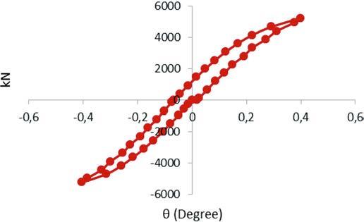
Fig. 8 M-q diagram for the frst load cycle of model B240-T300-H-Xmax-2-14
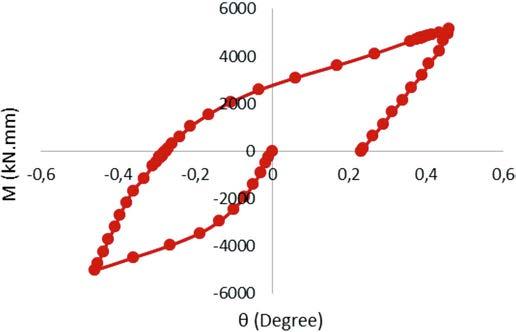
Fig. 9 M-q diagram for the frst load cycle of model L82- tp8
tp6-BS5(1) model increased by about 3.875% upon removal of the beam stifener. The maximum moment for the L82-tp10(4) model compared with the L91-tp6-BS5 (2) model increased by about 2.8% upon removal of the beam stifener.
After the elastic deformations were completed, as a result of fve hysteretic loadings, the energy dissipation values for the plastic deformations generated were 29, 23, 19, 16 and 13% respectively in the frst model, 35, 22, 17, 14 and 12% respectively in the second model, 30, 22, 18, 16 and 14% respectively in the third model, and 34, 23, 17, 14 and 12% respectively in the fourth model.
Model Maximum moment (KNmm) Cycle
1 5231.436
2 1576.575
3 5159.7
4 1863.225
5 5374.761
6 1992.29
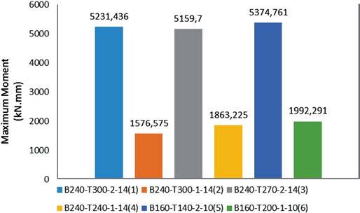
Fig. 10 Maximum moments of bolted T-connections
Therefore, after switching from one cycle to another, as a result of hysteretic loading, the energy dissipation capacity decreased by about 6, 4, 3 and 3 % respectively in the frst model, 13, 5, 3 and 2 % respectively in the second model, 8, 4, 2 and 2 % respectively in the third model, and 11, 6, 3 and 2 % respectively in the fourth model.
The energy dissipation values of top-and-seat-angle connections are presented in Fig. 11 and Tab. 6 for fve-cycle loading. The energy dissipation for the L91-tp6-BS5(2) model compared with the L91-tp6-BS5(1) model decreased by about 1.66, 19.18, 22.54, 24,99 and 28.04% upon removal of the stifener to the top and seat angle. The energy dissipation for the L82-tp10(4) model compared with the L82-tp8(3) model decreased by about 0.62,
Tab. 5 Energy dissipation values of bolted T-connections
Model B240-T300H-Xmax-2-14 (1) B240-T300-HXmin-1-14 (2) B240-T270-HXmin-2-14 (3) B240-T240-HXmin-1-14 (4) B160-T140-HXmax-2-10 (5) B160-T200-HXmin-1-10 (6)
Energy dissipation (kN.mm.degree) Cycle 1 700.65 88.746 694.74 302.77 1251.6 688.19
2 409.65 44.715 343.19 181.58 508.92 498.77
3 283.53 35.095 253.94 127.90 326.54 378.19
4 223.83 30.125 204.47 101.25 252.99 316.03
5 189.05 27.109 173.07 85.05 207.16 273.22
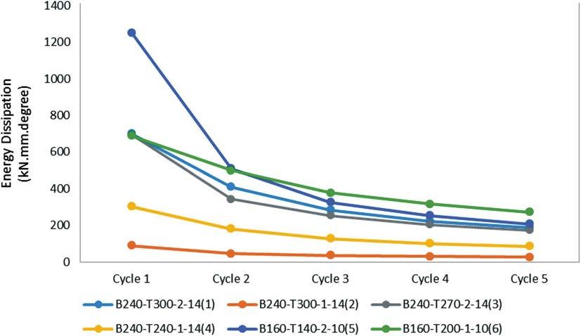
Fig. 11 Energy dissipation diagram for bolted T-connections
Tab. 6 Maximum moment values of top-and-seat-angle connections
Model Maximum moment (kNmm) Cycle
1 4944.639
4228.161
5143.971
4350.906
9.98, 16.53, 21.05 and 24.24% upon removal of the stifener to the top and seat angle. These results show that the rate of decrease for models with the stifener to the top and seat angle is higher than that of the models without stifeners for the angle. The energy dissipation for the L82-tp8(3) model compared with the L91-tp6-BS5(1) model increased by about 11.63, 4.89, 6.08, 8.85 and 10.36% with a reduction in the length L of the top and seat angle from 91 to 82 mm. The energy dissipation for the L82-tp10(4) model compared with the L91-tp6-BS5 (2) model increased by about 12.55, 14.6, 12.85, 13.41 and 14.86% with a reduction in length L of the top and seat angle from 91 to 82 mm. The energy dissipation for the L82-tp8(3) model compared with the L91-tp6-BS5(1)

Fig. 12 Maximum moments of top-and-seat-angle connections
model increased by about 11.63, 4.89, 6.08, 8.85 and 10.36% upon removal of the beam stifener. The energy dissipation for the L82-tp10(4) model compared with the L91-tp6-BS5 (2) model increased by about 12.55, 14.6, 12.85, 13.41 and 14.86% upon removal of the beam stifener.
6 Conclusions
The aim of this study was to analyse the behaviour of bolted T-connections and top-and-seat-angle connections
Tab. 7 Energy dissipation values of top-and-seat-angle connections
Energy dissipation (kN.mm.degree) Cycle L91-tp6-BS5 (1) L91-tp6-BS5 (2) L82-tp8 (3) L82-tp10 (4) 1 2847.04 2799.83 3221.69 3201.75
2 2222.55 1796.26 2336.81 2103.44
3 1799.45 1393.77 1915.94 1599.31
4 1505.33 1129.05 1651.42 1303.85
5 1310.02 942.618 1461.39 1107.14
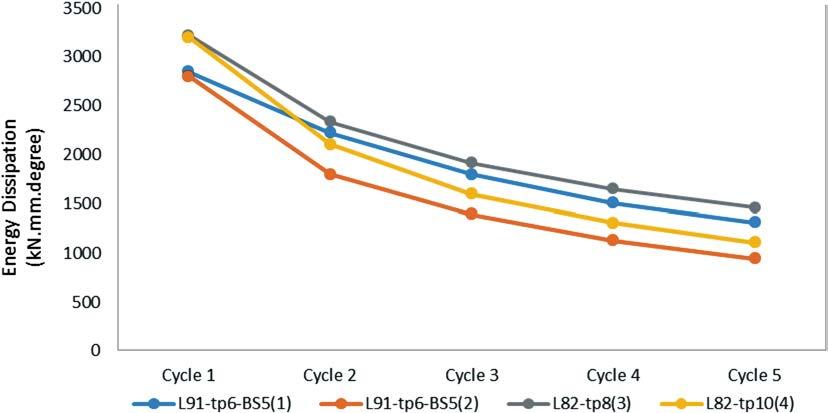
Fig. 13 Energy dissipation diagram for top-and-seat-angle connections
under hysteretic loading, evaluate the moment-rotation hysteresis curves and compare the quantity of energy dissipation that was derived from calculating the area under each loop of the moment-rotation curves for each model. Therefore, the general conclusions that can be presented from this work are as follows:
– For bolted T-connections • The maximum moment was increased by changing the thickness of the T-connections and changing the
X values of the T-connections from Xmin to Xmax. In addition, the moment was afected by changing the diameter of the bolts. • The displacement and rotational capacity were decreased by reducing the thickness of the connection’s web. Further, connections with long bolts showed a better capacity for rotation. By using bolts of the same grade and diameter, the rotational capacity was decreased when the ordinal number of web bolt rows in the connection was changed from two to one. • By using bolts of the same grade and diameter, the energy dissipation was decreased when the ordinal number of web bolt rows in the connection had changed from two to one.
• The energy dissipation decreased by about 2–29% after switching from one cycle to another in fve hysteretic loadings. – For top-and-seat-angle connections: • The moment was increased by using the stifener in the beam web. Increasing the angle length and the thickness of stifeners in connections also caused an increase in moment values. • The displacement was increased by decreasing the angle length. • For the stifened top-and-seat-angle connections, the rotational capacity and energy dissipation values were increased by decreasing the angle length. • The energy dissipation decreased by about 2–13% after switching from one cycle to another in fve hysteretic loadings.
During this study we used only von Mises stresses in the computer models and plastic deformations occurred as a result of these stresses. As a result of plastic deformations, energy dissipation occurred due to hysteretic loading. However, the temperature due to plastic deformation during the test was not considered in the models.
References
[1] Babu, S.; Sreekumar, S. (2012) A study on the ductility of bolted beam-column connections in: International Journal of Modern Engineering Research (IJMER) 2(5), pp. 3517–3521. [2] Sag˘ırog˘lu, M.; Aydın, A. C. (2015) Design and Analysis of non-linear space frames with semi-rigid connections in:
Steel and Composite Structures 18(6), pp. 1405–1421. [3] Faella, C.; Piluso, V.; Rizzano, G. (2000) Structural steel semirigid connections: theory, design and software in: New
Directions in Civil Engineering., CRC Publishers. [4] Díaz, C.; Martí, P.; Victoria, M.; M. Querin, O. (2011) Review on the modeling of joint behavior in steel frames in:
Journal of Constructional Steel Research 67, pp. 741–758. [5] Wilson, W. M.; Moore, H. F. (1917) Tests to determine the rigidity of riveted joints in steel structures. Engineering Experiment Station, Bulletin 104, University of Illinois, Urbana, USA. [6] Goverdhan, A. V. (1984) A collection of experimental moment-rotation curves and valuation of prediction equations
for semi-rigid connections (master thesis), Vanderbilt University, Nashville (TN). [7] Nethercot, D. A. (1985) Steel beam-to-column connections: a review of test data and its applicability to the evaluation of joint behaviour in the performance of steel frames. CIRIA report 338. [8] Nethercot, D. A. (1985) Utilization of experimentally obtained connection data in assessing the performance of steel frames in: Chen W. F. (ed.) Connection fexibility and steel frames. Detroit: Proc. of session sponsored by ASCE
Structural Division. [9] Steel Structures Research Committee (1931) First report.
London: Dept. of Scientifc & Industrial Research, HMSO. [10] Steel Structures Research Committee (1934) Second report.
London: Dept. of Scientifc & Industrial Research, HMSO. [11] Steel Structures Research Committee (1936) Final report.
London: Dept. of Scientifc & Industrial Research, HMSO. [12] Kishi, N.; Chen, W. F. (1986) Steel connection data bank program, Structural Engineering, 2nd ed., Report No. CE-
STR86-18, School of Civil Engineering, Purdue University,
West Lafayette. [13] Abdalla, K. M.; Chen, W. F. (1995) Expanded database of semi-rigid steel connections in: Computers & Structures 56(4), pp. 553–564. [14] Weynand, K. (1992) SERICON I-databank on joints building frames in: Proc. of COSTC1, 1st State of the Art Workshop on Semi-Rigid Behavior of Civil Engineering Structures, pp. 463–474. [15] Weynand, K.; Huter, M.; Kirby, P. A.; Simões, da Silva L. A.
P.; Cruz, P. J. S. (1998) SERICON-databank on joint in building frames in: Proc. of COSTC1, 1st State of the Art
Workshop on Semi-Rigid Behavior of Civil Engineering
Structures, pp. 463–474. [16] Gerardy, J. C.; Schleich, J. B. (1991) Semi-rigid action in steel frame structures. Report No. 7210-SA1507, Arbed Recherches, Luxembourg. [17] Cruz, P. J. S.; Simões da Silva L. A. P.; Rodrigues D. S.;
Simões R. A. D. (1998) SERICON II, database for the semirigid behaviour of beam-to-column connections in seismic regions in: Journal of Constructional Steel Research 46(1–3), pp. 233–234. [18] Astaneh Asl, A.; Nader, M. N.; Malik, L. (1989) Cyclic Behavior of Double Angle Connections in: J.Struct.Eng. 115(5), pp. 1101–1118. [19] Azizinamini, A.; Bradbum, J. H.; Radziminski, J. B. (1985)
Static and cyclic behavior of semi-rigid steel beam-column connections, Dept. of Civ. Engrg., Univ. of South Carolina,
Columbia, S.C. [20] Chen, W. F.; Lui, E. M. (1991) Stability Design of Steel
Frames. London: CRC Press. [21] Abolmaali, A.; Kukreti, A. R.; Razavi, H. (2003) Hysteresis
Behaviour of Semi-Rigid Double Web Angle Steel Connections in: Journal of Constructional Steel Research 59, pp. 1057–1082. [22] Shi, Y.; Shi, G.; Wang, Y. (2007) Experimental and Theoretical Analysis of the Moment-Rotation Behaviour of Stifened Extended End-Plate Connections in: Journal of Constructional Steel Research 63, pp. 1279–1293. [23] European Committee for Standardization (CEN) (2005)
Design of steel structures. Part 1.8: Design of joints. Stage 49 draft, Brussels. [24] Maali, M.; Kılıç, M.; Aydın, A. C. (2016) Experimental
Model of the Behaviour of Bolted Angles Connections with
Stifener in: International Journal of Steel Structures 16(3), pp. 719–733. [25] Maali, M.; Kılıç, M.; Sag˘ırog˘lu, M.; Aydın, A. C. (2017) Experimental Model for Predicting the Semi-Rigid Connections Behaviour with Angles and Stifeners in: Advances in
Structural Engineering 20(6) pp. 884–895. [26] Maali, M.; Kılıç, M.; Aydın, A. C. (2019) Experimental behavior of bolted connections with stifeners in: Steel Construction Design and Research 12, No. 2, pp. 105–113. [27] Maali, M.; Kılıç, M.; Yaman, Z.; Ag˘cakoca, E.; Aydın, A. C. (2019) Buckling and Post-Buckling Behavior of Various
Dented Cylindrical Shells Using CFRP Strips Subjected to
Uniform External Pressure: Comparison of Theoretical and
Experimental Data in: Thin-Walled Structures 137, pp. 29–39,. [28] Maali M.; Aydin A. C.; Showkati H.; Sag˘ırog˘lu M.; Kiliç M. (2018) The efect of longitudinal imperfections on thinwalled conical shells in: Journal of Building Engineering 20, pp. 424–441. [29] Sagiroglu, M.; Maali, M.; Kılıç, M.; Aydın, A. C. (2018) A
Novel Approach for Bolted T-Stub Connections in: International Journal of Steel Structures 18, No. 3, pp. 891–909. [30] Aydin, A. C.; Özkaya, S. G. (2018) The fnite element analysis of collapse loads of single-spanned historic masonry arch bridges (Ordu, Sarpdere Bridge) in: Engineering Failure
Analysis 84, pp. 131–138. [31] Aydın, A. C.; Maali, M.; Kılıç, M.; Sagiroglu, M. (2015) Experimental Investigation of Sinus Beams with End-Plate
Connections in: Thin-Walled Structures 97, pp. 35–43. [32] Aydın, A. C.; Kılıç, M.; Maali, M.; Sagiroglu, M. (2015) Experimental Assessment of the Semi-rigid Connections Behavior with Angles and Stifeners in: Journal of Constructional Steel Research 114, pp. 338–348. [33] Maali, M.; Aydin, A. C.; Sagiroglu, M. (2015) Investigation of innovative steel runway beam in industrial building in:
SADHANA Academy Proc. in Engineering Sciences, pp. 2239–2251. [34] Abidelah, A.; Bouchair, A.; Kerdal, D. E. (2012) Experimental and Analytical Behavior of Bolted End-Plate Connections with or without Stifeners in: Journal of Constructional Steel Research 76, pp. 13–27. [35] Limaa, L. R. O.; Veradea, S. A. L.; Vellascob, P. C. G.; Silvac, L. S. (2002) Experimental and mechanical model for predicting the behavior of minor axis beam-to-column semi-rigid joints in: International Journal of Mechanical
Sciences, 44, pp. 1047–1065. [36] Korucuk, F. M. A.; Maali, M.; Kılıc, M.; Aydın, A. C. (2019)
Experimental Analysis of the Efect of Dent Variation on the Buckling Capacity of Thin-Walled Cylindrical Shells in:
Thin-Walled Structures 143, pp. 1–13. [37] Sag˘ırog˘lu, M. (2018) Experimental evaluation of the postfre behavior of steel T-component in the beam-to-column connection in: Fire Safety Journal 96, pp. 153–164. [38] Sagiroglu, M., Aydin, A.C. (2015) Design and analysis of non-linear space frames with semi-rigid connections in:
Steel and Composite Structures, Int. Journal 18, pp.1405–1421.
Authors
Abdulkadir Cüneyt Aydin (corresponding author) acaydin@atauni.edu.tr Ataturk University Engineering Faculty Department of Civil Engineering 25030, Erzurum Turkey
Aysan Ardalani aysan.ardalan@gmail.com Ataturk University Engineering Faculty Department of Civil Engineering 25030, Erzurum Turkey
Mahyar Maali mahyar.maali@erzurum.edu.tr Erzurum Technical University Faculty of Engineering & Architecture Department of Civil Engineering 25050, Erzurum Turkey Mahmut Kiliç mahmut.kilic@atauni.edu.tr Ataturk University Engineering Faculty Department of Civil Engineering 25030, Erzurum Turkey
How to Cite this Paper
Aydin, A. C.; Ardalani, A.; Maali, M.; Kiliç, M. (2021) Numeric modelling of innovative semi-rigid connections under hysteric loading. Steel Construction 14, No. 1, pp. 22–34. https://doi.org/10.1002/stco.201900037 This paper has been peer reviewed. Submitted: 29. August 2019; accepted: 24. January 2020.
Prof. Markus Knobloch, Prof. Ulrike Kuhlmann, Prof. Andreas Taras et al. Structural member stability in the second generation of Eurocode 3
26 March 2021 · 10.00–12.00 a.m. CET
www.ernst-und-sohn.de/stco-seminar
Partnership with academic institutions
Ernst & Sohn with their parent company John Wiley & Sons, Inc. has signed a contract with the Projekt DEAL in 2019. The Projekt DEAL represents as a consortium about 700 academic institutions in Germany. In order to support the general furthering of scientific research, Wiley and the Project Deal have together initiated three new initiatives as a partnership. The trendsetting agreement will enable researchers from all the Projekt DEAL institutions to publish articles in Wiley journals with open access. You can find more information about the agreement in the press release from Wiley. Authorised authors from participating institutions can publish with open access and profit from reading access to the journals of Wiley and
Ernst & Sohn.
Authors from Projekt DEAL institutions can publish research and overview articles with open access in Wiley journals, maintaining the copyright to their works without further costs. Ernst & Sohn is involved in this partnership with the journals Civil Engineering Design and Steel Construction and from 2019 will offer publications under the open access model. Print issues of Steel Construction, which is also available in a printed version, can be ordered in addition to the online variant. This provides the reader with supplementary industry reports and product information.
If you have any questions, please contact: marketing@ernst-und-sohn.de
For more information and to check eligibility, visit: www.ernst-und-sohn.de/DEALWiley
2
Volume 12 May 2019 ISSN 1867-0520
Steel Construction
Design and Research
–––––––– Eurocode 4 Development Local buckling strength of HSS stub cruciform column Reusing steel parts from single-storey buildings MOCAPE Experimental behaviour of bolted connections with stiffeners Box girder selection for cable-supported railroad bridges Tension-shear interaction of HS bolts in fre Dynamic behaviour of unbraced steel frames –– resting on soft ground European buckling curves for aluminium members Review of Wöhler’s fatigue strength research
VOLUME 2 / OCTOBER 2020 ISSN 2625-073X 04
Chefredakteur: Prof. Dr. Konrad Bergmeister Editorial Board: Prof. Dr. Peter Mark, Prof. Dr. Manfred Curbach, Prof. Dr. Oliver Fischer, Prof. Dr. Jan Akkermann, Dipl.-Ing. Torsten Schoch Call for Papers Civil Engineering Design
-hybride Open-Access Zeitschrift, ausschließlich Online -engl. Sprache, 6 Ausgaben pro Jahr -interdisziplinärer und materialunabhängiger Ansatz -fokussiert auf wissenschaftliche Veröffentlichungen -erfahrener Beirat, kurze Begutachtungs- und Veröffentlichungszeiträume -Manuskripteinreichung und Begutachtungsverfahren über ScholarOne -Einfachblindgutachten unabhängiger Experten

Die Zeitschrift Civil Engineering Design befasst sich mit innovativen theoretischen, numerischen und experimentellen Methoden für aktuelle und neuartige Baustoffe wie Beton, Stahl, Aluminium, Glas, Holz, Mauerwerk, Verbundwerkstoffe und allen Aspekten der konzeptionellen, baulichen und leistungsbezogenen Planung, der experimentellen Prüfung und der numerischen Modellierung von Errichtung, Instandhaltung und Abriss für den gesamten Lebenszyklus von Bauwerken. Abgerundet wird dies durch die Einbeziehung der Geotechnik und Bodenmechanik aus bautechnischer Sicht.
VOLUME 2 / DECEMBER 2020 ISSN 2625-073X 05/ 06
EINREICHUNGEN
Sie sind eingeladen am Start dieser neuen Zeitschrift aktiv teilzunehmen, sie zu formen und die Entwicklung ihrer Ausrichtung zu bestimmen. mc.manuscriptcentral.com/cend Dirk Jesse (Managing Editor) + 49 (0)30 470 31-275 dirk.jesse@wiley.com