
118
PROJECT INTERVENTION AND STRATEGY
119
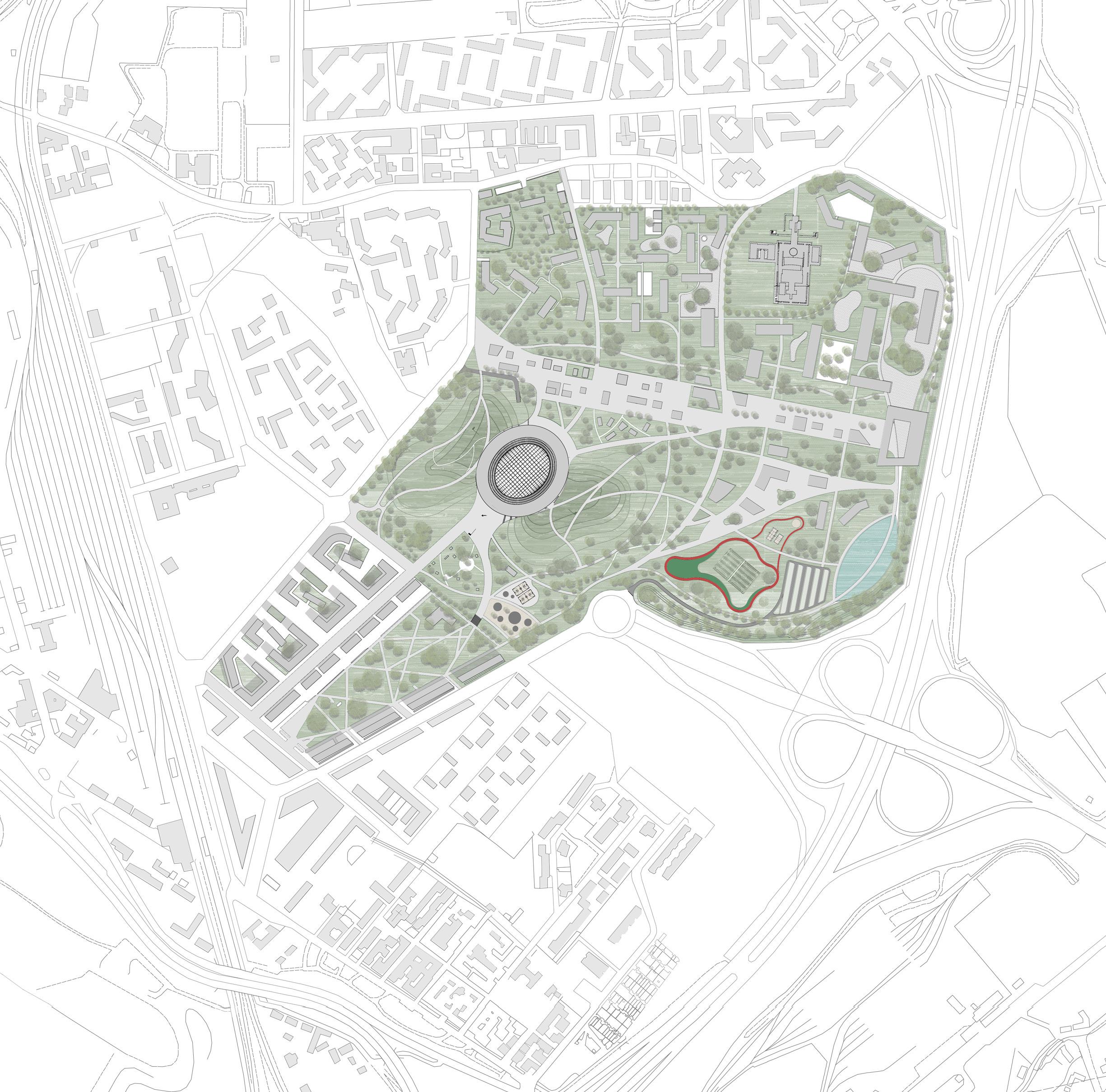
MASTER PLAN CONCEPT PROPOSAL
MASTERPLAN PROPOSAL
PROJECT INTERVENTION AND STRATEGY
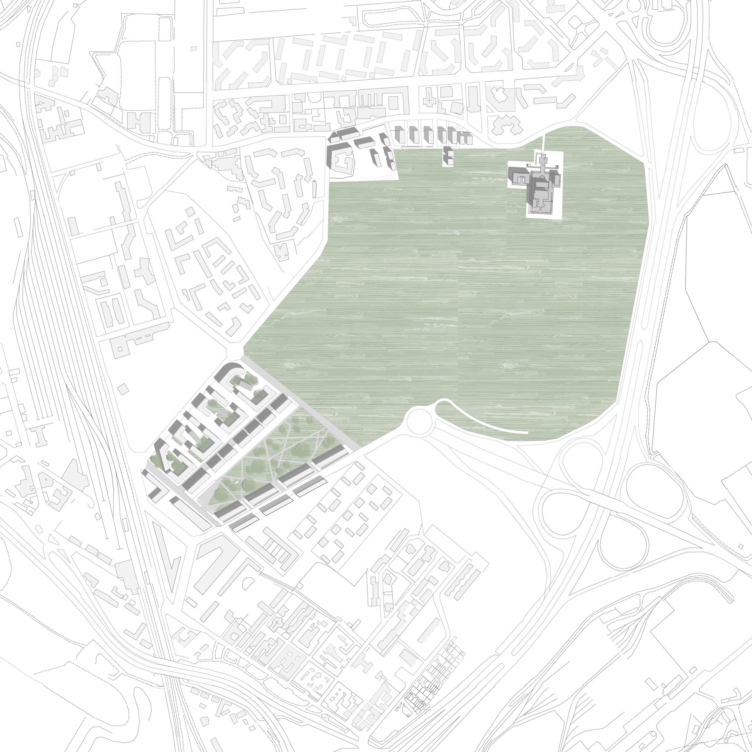
Following our analysis for the masterplan proposed by Foster & Partners, we were able to better understand the site and highlight the critical points where we must tackle and achieve to design a well coherent and functional masterplan.
We focused heavily on the perseverance of greenery already found in site, especially that our site is included in Milan’s PGT and Vision for 2030, regarding sustainability, greenery, and parks around the city.
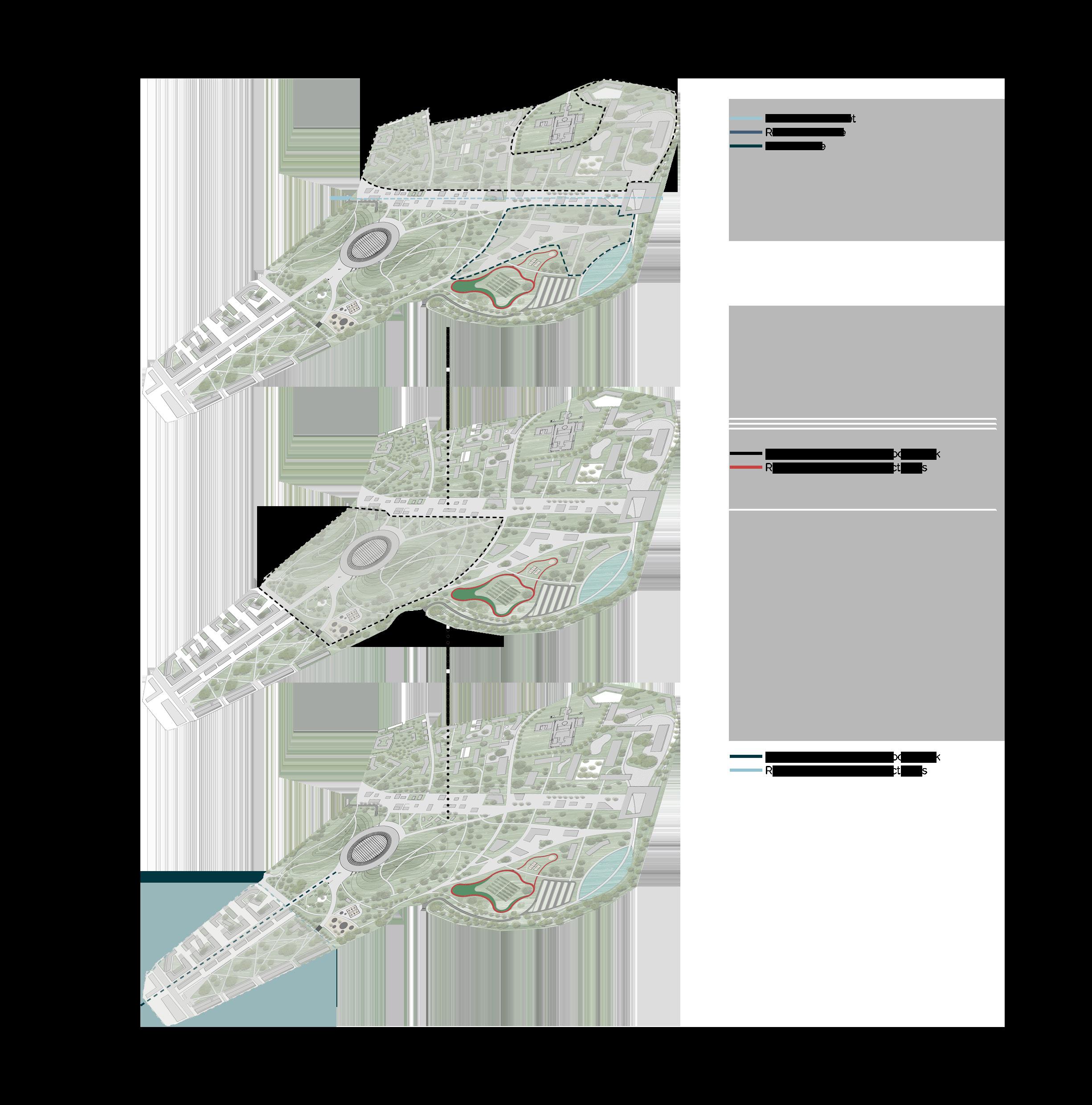
In our approach for the designed master plan, we proceeded in line with the settlement, maintaining the current configuration, extending the existent boulevard which connects Rogoredo station and our site, reaching a swelling place forming the arena’s main square and platform. The axis itself deviates into different paths allowing for dynamic circulation, connecting different areas, from outdoor sport park, outdoor green gathering area, to the commercial street designed as well. The zoning areas are connected through major and minor pathways, allowing the direct relation while each preserving its own space through different compositional forms.
The development of the park in which the sport hall can be found is designed to be defined in its geometrical shape (trapezoidal) with a large usable space, with different outdoor sport and exercise facilities, allowing for continuous visual and physical relation with the sport hall. Moreover, the arena is covered on the sides with green hills, bringing elevation for a flat terrain for a better experience and relation of Santa Giulia.
122
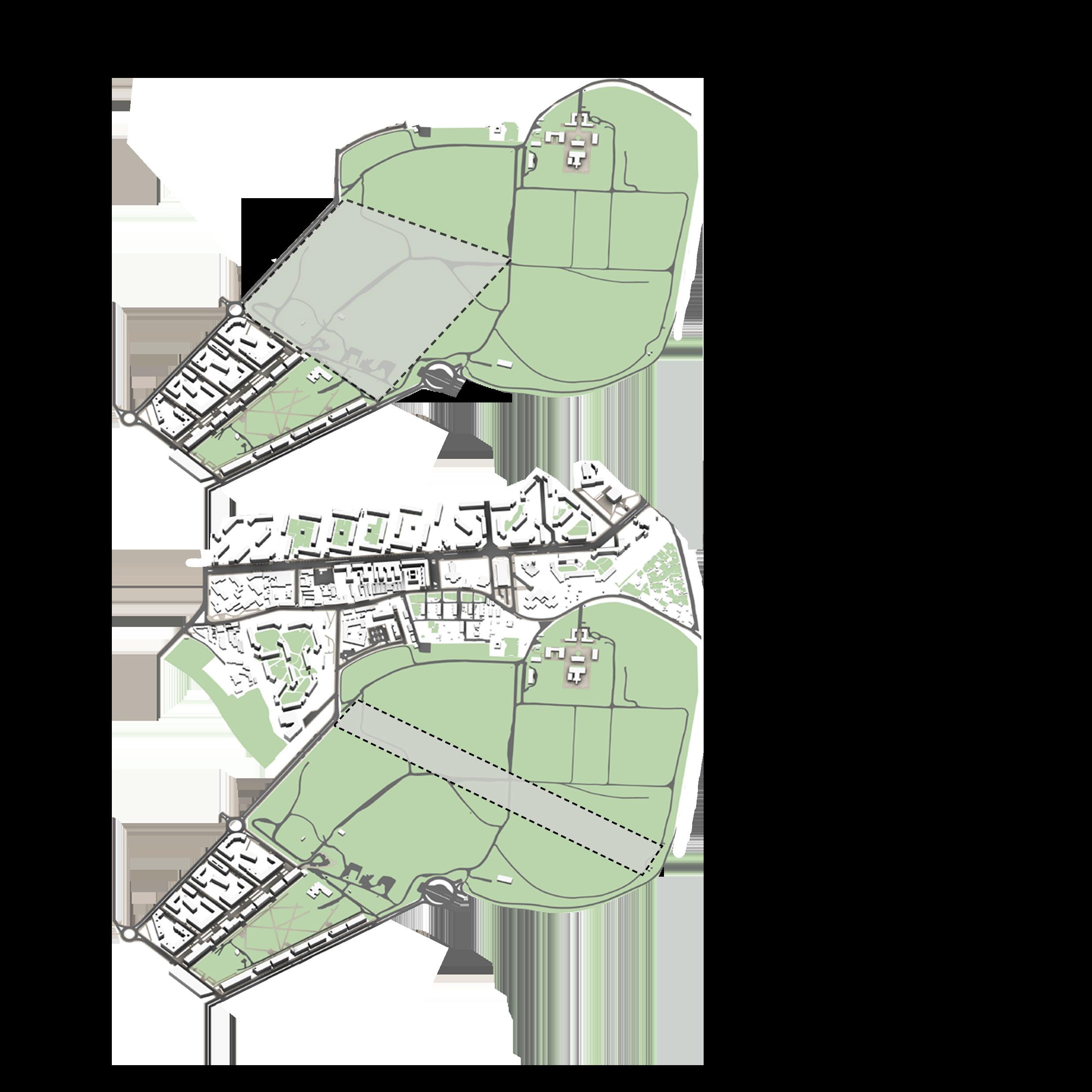
Extension of the current configuration and settlement; the existing boulevard of Santa Giulia and the current park in between the already constructed residential buildings.
Respecting the surrounding neighborhood and configuration of the building typologies. Such strategy is followed in our masterplan for the residential building to allow a better continuation and blending of the district.
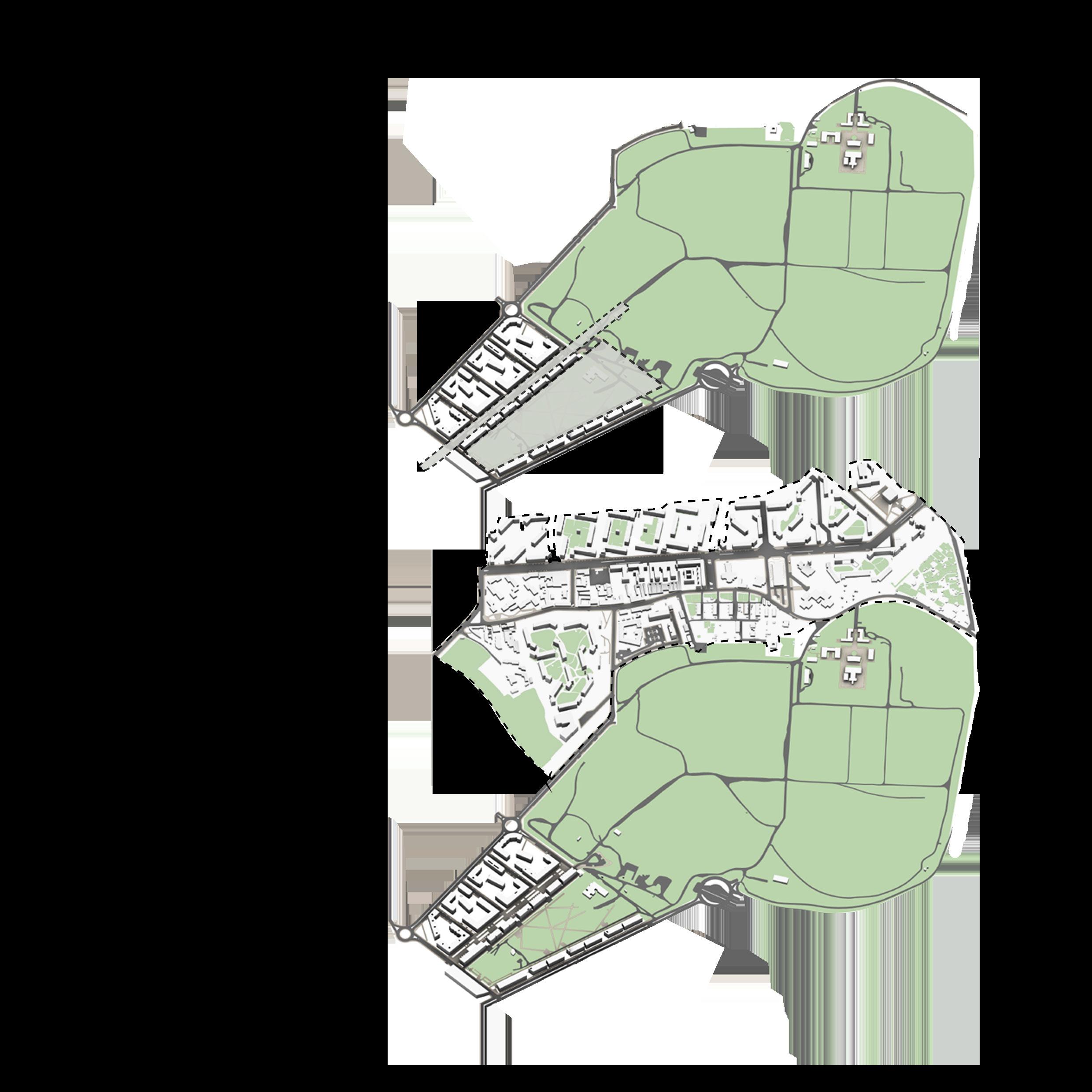
A defined geometric park of a trapezoidal shape, including the sports hall and different sport facilities, allowing for connectivity and constant relation in between.
Designing a commercial street, acting as a linking point between the different zoning areas. It has the capability to withstand the flow of people from the residential area as well as the sports area and business zone. It is an overall leisure and functional addition to the masterplan, acting as a gathering zone with the rest.
127
128
CONCEPT STRATEGY
129
OPEN SPACES AND LANDSCAPE INTEGRATION
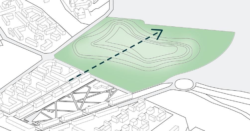
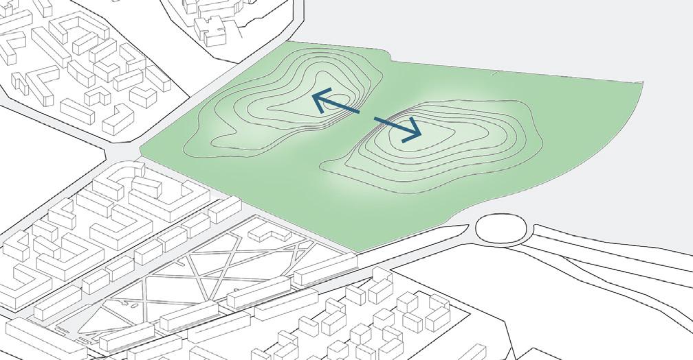
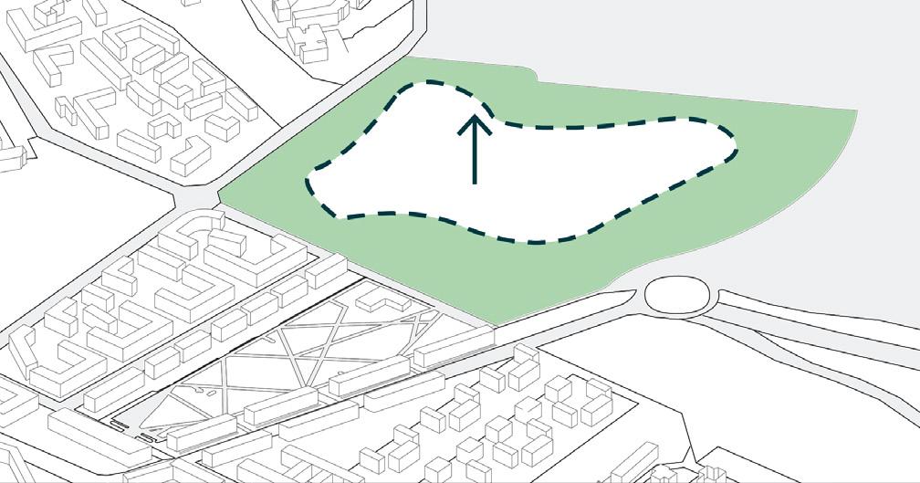
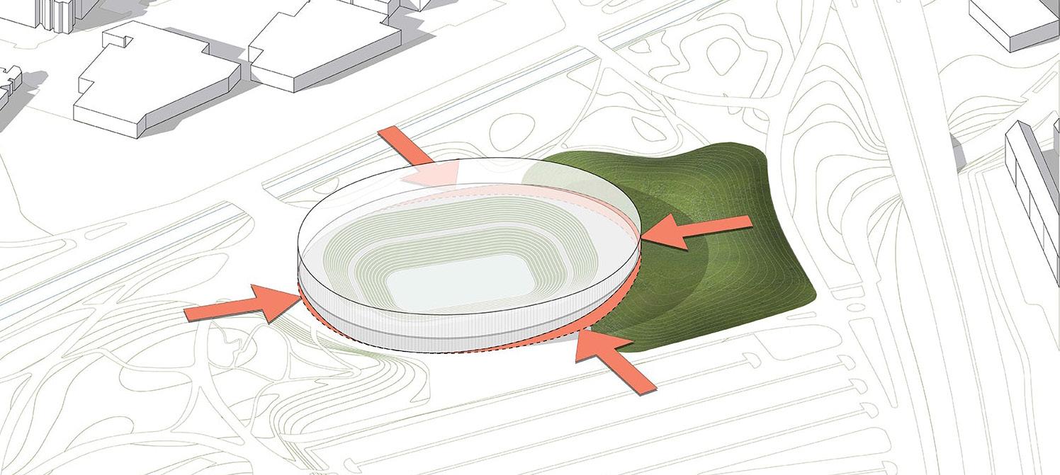
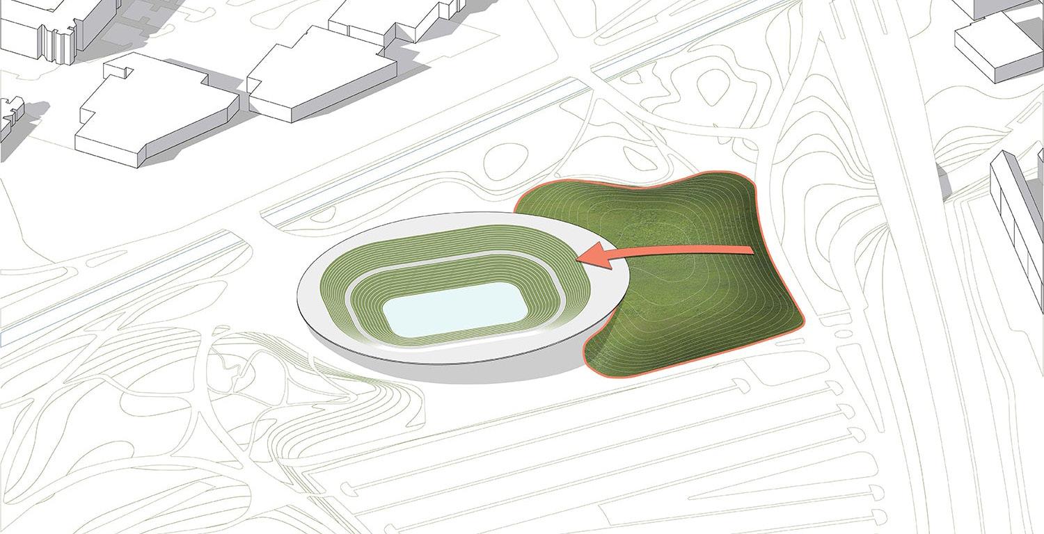
The concept of our building is based on a strong relationship with the context and the possible dialogues we can establish with it. The first step to build the concept was based on a common characteristic of important Milanese open spaces: the call for height. As for Monte Stella, Parco del Portello and Parco Lambro, the proposition of a hill relates with the symbolic aspect of our project, in which the height in a flat city as Milan brings relevance In the context. The second step consisted of frank dialogue with the existing context. Taking advantage of the boulevard existent in Santa Giulia, which presents good architectural qualities and connects the place with Rogoredo Station, we establish that this axis will intersect our hill and create the opportunity to insert our Arena. The third step consists of understanding how we can model the landscape to create the insertion of the Arena. Inserting the Arena intrinsical with the hill proposes a direct dialogue with the landscape and a continuity from the hill into the building.
After that, taking as reference the relationship between emptiness and fullness in relevant buildings in Milan, as Rotonda Della Besana, Lazzaretto, and Galleria Vittorio Emanuelle, whose space is a central construction, surrounded by rings of void and a perimeter construction, we defined our building as the main construction (the sports venue), surrounded by a void (the gallery) and a perimeter construction
130
Figure 55. Building concept diagram - Landscape . Source: Authors.
(the community uses).
It is then necessary to cover these volumes. To make that, we establish 3 different kinds of cover with different kinds of solar penetration: the ETFE cushion roof for the Arena, the translucent polycarbonate cover for the gallery, and the opaque roof for the community uses. These different covers will allow different kinds of solar penetrations according to the use that we have below and the light intended. Finally, we need to make openings in the façade to create the entrance. This is made by an organic smooth movement that follows the inclination of the hill and offers the entrances in the west-east axis, and shading in the south-north axis.

131 BUILT AND EMPTY
Figure 56. Building concept diagram - Building. Source: Authors.
132
BUILDING PROGRAM
133
CASE STUDIES
135
SAP GARDEN MUNICH
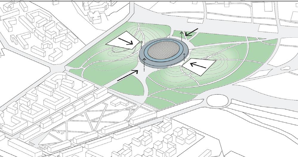
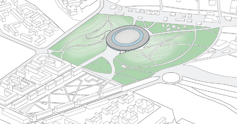
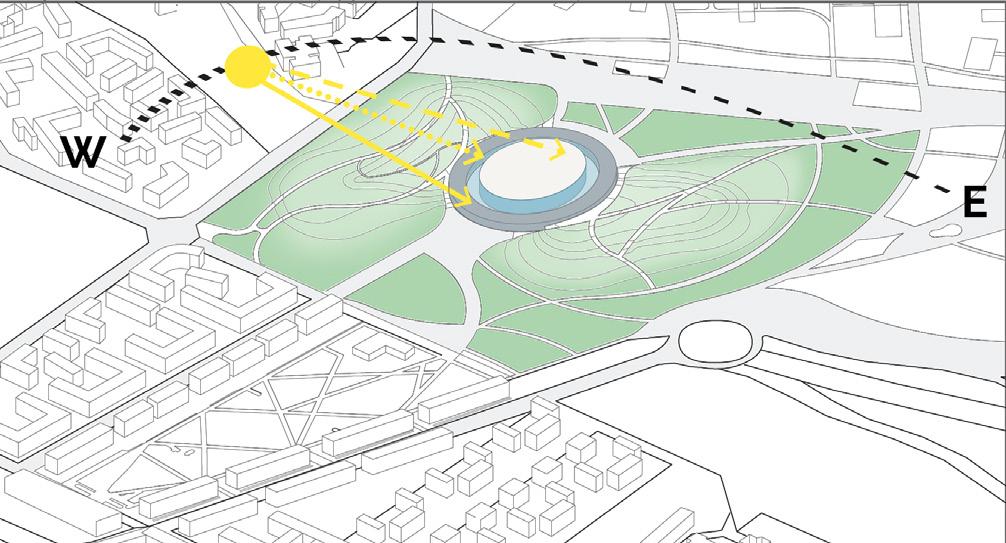
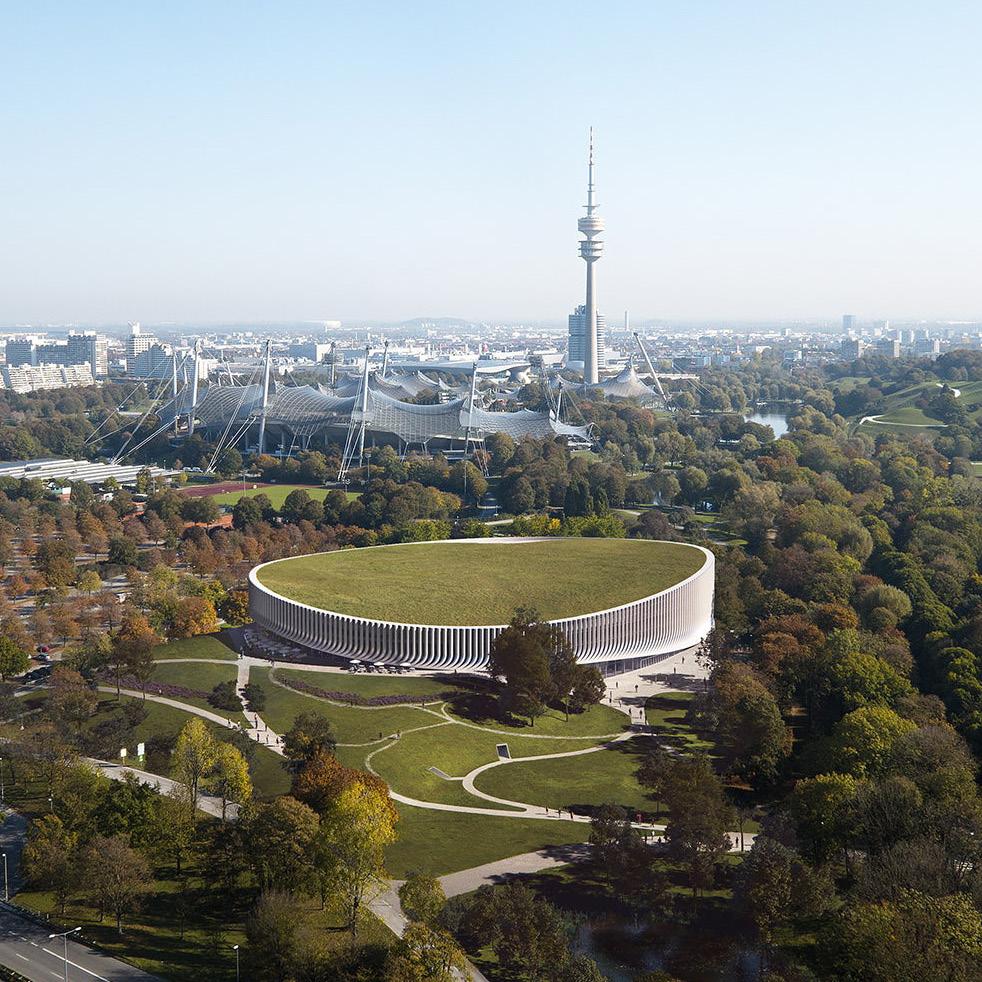
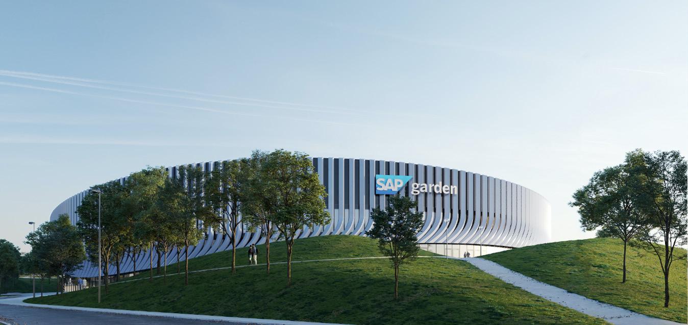
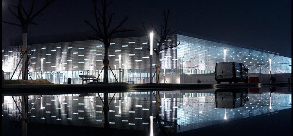
One of the first projects to inspire our approach was SAP Garden, in Munich, by 3XN Architects (Figure 57) The obvious relationship it had with our park-like context helped us to explore how the building program would relate, at first, with its context, and then also with the topography. In SAP Garden, the multipurpose Arena (for Hockey and Basketball) takes advantage of the topography to create separated entrances, splitting the flows of spectators, players, and staff (Figure 58 and Figure 59). This division of entrances creates a more liveable portion of the Arena, where spectators and the community can enjoy a cafè and other uses in daily life. On game days, the spectators have direct access to both levels: the lower stands, are level with the street; the upper stands are leveled with the hill created in the park.
136
Figure 57. SAP Garden Multicomplex Arena by 3XN Architects. Source: 3XN Architects.
Figure 58. Topography work in SAP Garden. Source: 3XN Architects.
Figure 59. Flows division in SAP Garden. Source: 3XN Architects.
In an agreement among private and public stakeholders, SAP Garden was designed for 8,000 hours of use per year, proposing a frank dialogue with the community. This will catalyze its use for skating and other activities on non-event days by clubs, schools, and the general public.
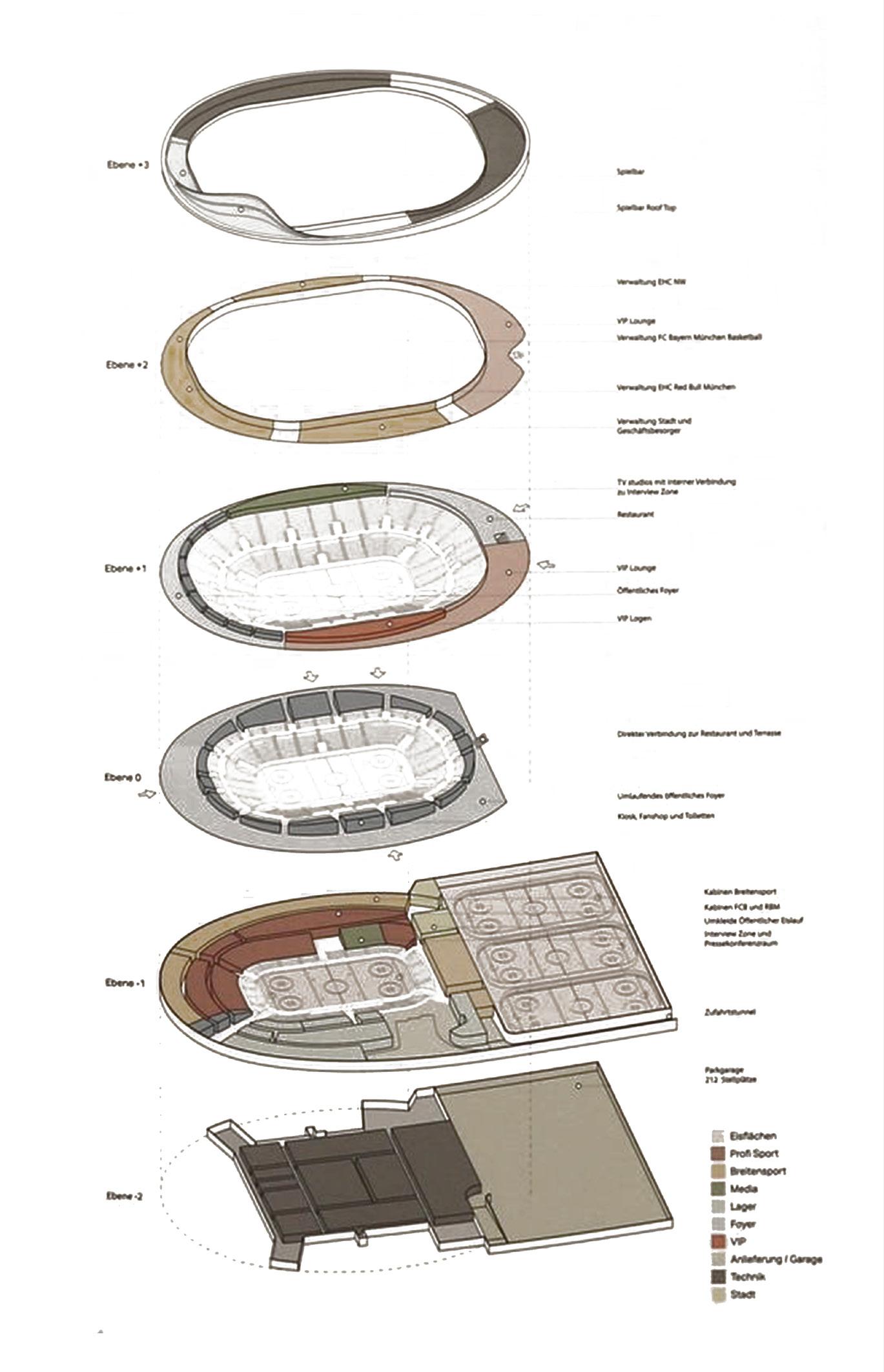
SAP Garden was also considered when distributing the functions across the building. Placing VIPs, restaurants, and TV zone in upper levels, leaving the public uses on the ground floor, the fields in the underground level, and the technical below it are characteristics taken into consideration when designing in Santa Giulia.
137
Figure 60. Functions arrangement diagram. Source: 3XN architects.
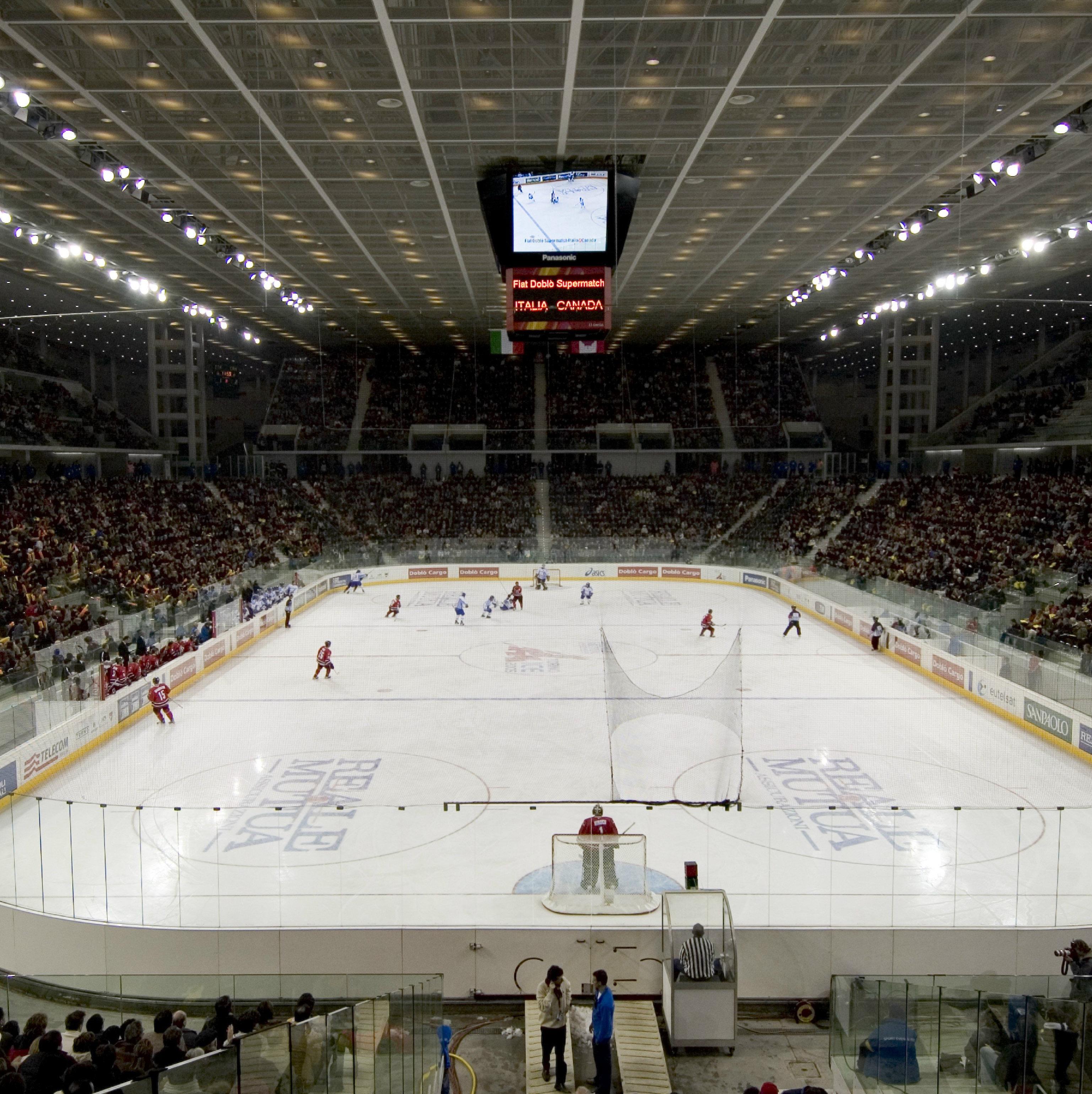
PALASPORT TORINO
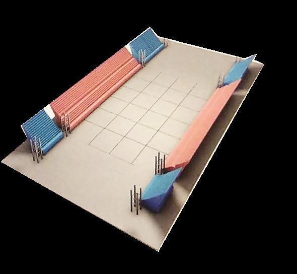
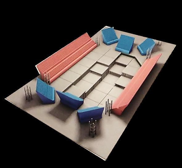

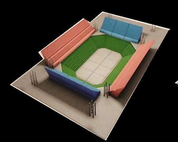
The Palasport Torino is the Ice Hockey Arena built for the 2006 Winter Olympics in Torino (Figure 62). It was designed by Arata Isozaki and Arup and shows some interesting programmatic characteristics that can be an inspiration for Arena designers. The most impressive characteristic is certainly the concept of flexibility. To allow the most diverse configurations of the field possible, Isozaki presents a system of elevating platforms, displaceable stands, and telescopic seats that makes possible completely different kinds of arrangements. Figure 61 shows in the left the configuration for hockey games, Going to the right, we see how the telescopic seats can be folded to open space in the underground level for sports with bigger fields. Then, the plane of the field can be elevated and leveled with the ground floor to host bigger events. Finally, the stands can be displaced and open space for uses and big conferences,
138
Figure 61. - Different stands and fields configurations. Source: Arup, 2007 Figure 62. PalaIsozaki, Torino. Source: Arup, 2007
EDEN PROJECT
The Eden Project by Grimshaw Architects is a bubble-like Biomes nestling in Cornwall, UK (Figure 63). It is a Geodesic dome of triple-layered ETFE (ethylene tetrafluoroethylene copolymer) Cushions that cover gardens inspired in the Mediterranean and the Rainforest Biome.
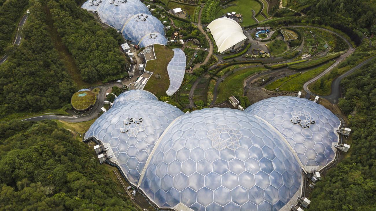
The Geodesic dome is incredibly light and was taken into consideration for Santa Giulia’s case as a way of covering a large span with the less material possible. The dome idea was very present since the beginning of our studies for the sports hall in Santa Giulia, as a way to allow more flexibility in the functions below it.
139
Figure 63. Eden project by Grimshaw Architects. Source: edenproject.com
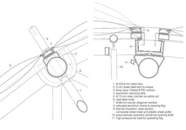
Figure 64. ETFE Cushion adopted in the dome. Source: Kaltenbach, 2011
PREVIOUS PROJECT
Our first attempt to design the Palasport for Santa Giulia (Figure 65) was a laboratory for experimentations. We tested some concepts (a bowl in the dome), some integration and flexibility approaches, and learned a lot about the complexity of making an Arenal. Concerning the program, it set the technical basis and also the intention of making the Palasport a place for every day, with plenty of uses for the community in the surroundings.
We had though some basic problems that worked as learning for us. Among them: The dimensions of making a complete dome, which was out of scale for the context of Santa Giulia;
- The “façade inside a facade” approach, which was unjustifiable;
- The underground mall, which demanded too much
140
Figure 65. First attempt project for Santa Giulia Sports Hall. Source: Authors.
Figure 66. First attempt project for Santa Giulia Sports Hall. Source: Authors.
Figure 67. First attempt project for Santa Giulia Sports Hall. Source: Authors.
groundwork;
- The unsustainable approach, in terms of keeping the place warm;
- The design of the position of the Arena, combined with the landscape and buildings around, was poor. It was certainly a great experience to redesign the building for the thesis work with a more mature view of the challenges we were going to face.
141
Figure 68. First attempt project for Santa Giulia Sports Hall - Exploded view. Source: Authors.
PROGRAM
143
THE 2026 WINTER OLYMPICS MASTERPLAN
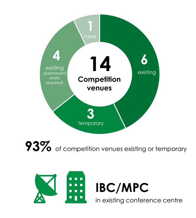
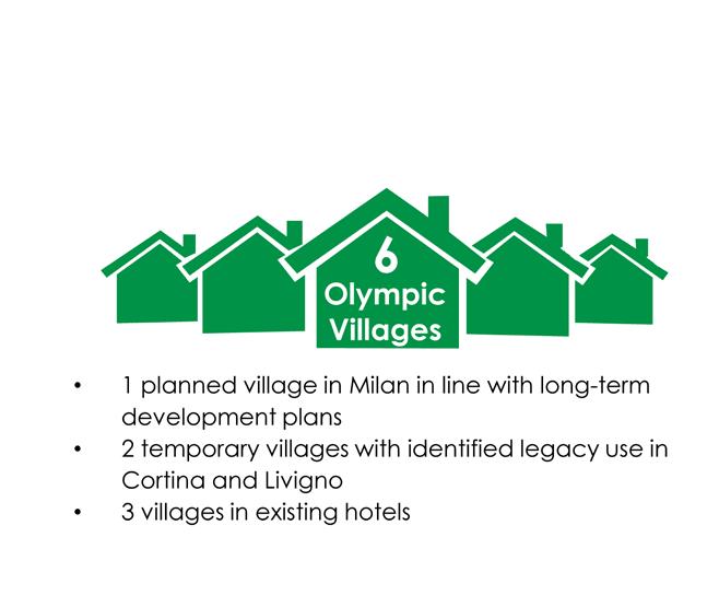
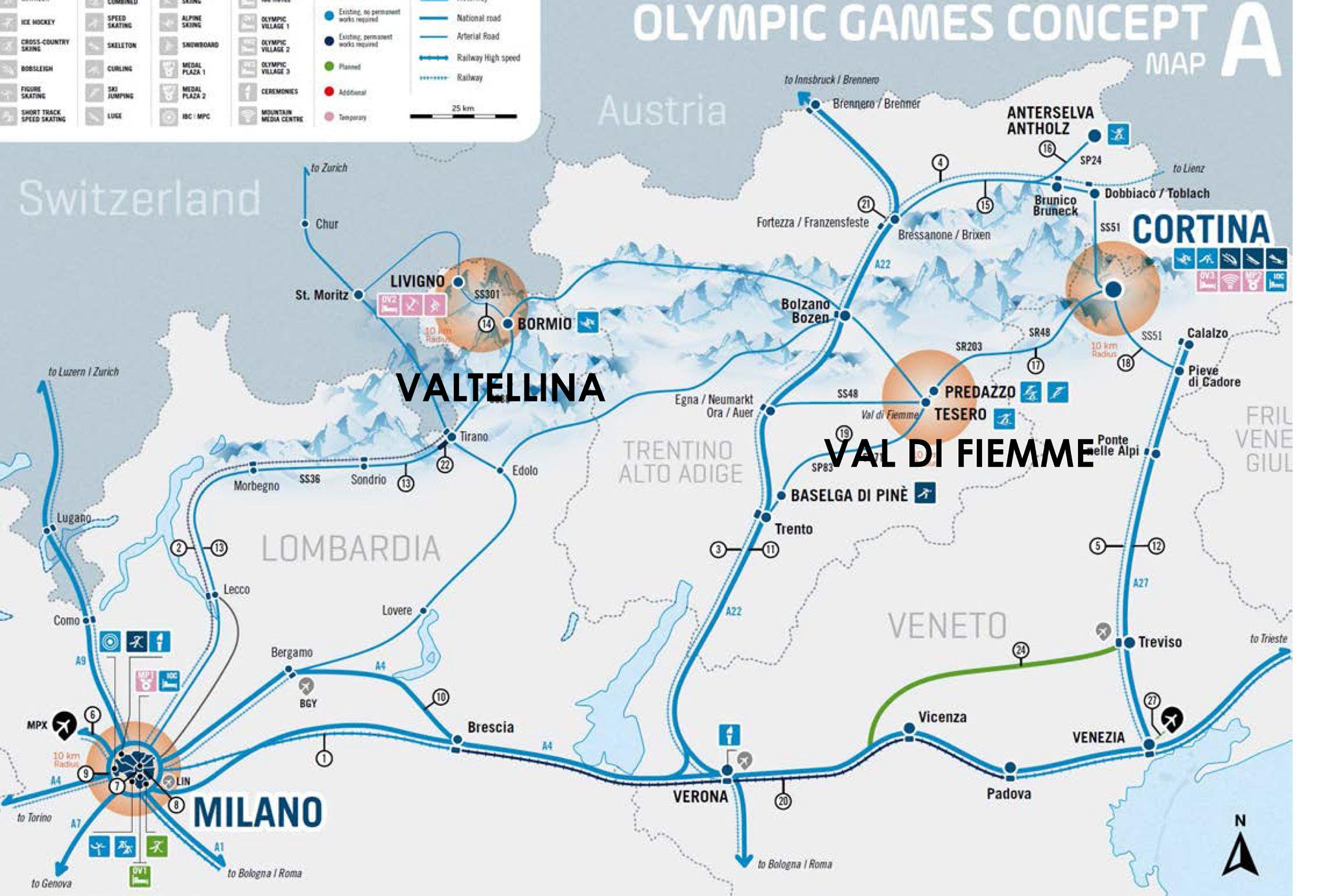
The Winter Olympic Games of Milano Cortina have a program distributed around 4 cities that will host all sports competitions: Cortina, Milano, Valtellina e Val di Fiemme. Figure 69 shows the distribution of the sports venues around these cities. Embracing the new 2020 Olympic agenda its master plan attempts to built permanent as little as possible, having 93% of the competition sites (13/14) being either existing or temporary ( Figure 70 ).
Milan, in a closer look, will host only 3 sports: Ice hockey 1 and 2, figure skating, and short track. These sports will be distributed around the city in 3 venues: Milano Hockey Arena (PalaSharp), Assago Forum, and PalaItalia Santa Giulia. The PalaItalia Santa Giulia is the only new venue to be constructed in Milan, to host the Ice Hockey games. Aligned with the new concerns of Olympic games, this new Arena has to leave a strong legacy to the city, and that is why it is important to be built as a Multipurpose Arena and also be used in daily life. Besides the competition site, only the new Olympic Village (Milan) will be a completely new venue. It is important to know that both constructions (PalaItalia Santa Giulia and the Olympic Village) are inserted in a bigger Milanese plan, working as catalysts for urban regeneration, Specifically, PalaItalia Santa Giulia is being developed in a major plan running by a private developer, which will build a
144
Figure 70. - Different stands and fields configurations. Source: Arup, 2007
completely new neighborhood in Santa Giulia and plans also to have public services like the Sports venue.
It is important to notice that some constraints to the PalaItalia were proposed by this private developer. As an independent architecture work, this project aims at providing the best proposal and that means not following exactly all the conditions provided by the developer. That is why, for example, the integration between landscape, neighborhood, and Arena was completely redesigned in this work. Also necessary to mention that the 15000 seat constraint was also intended by the developer. However, the International
145
Figure 69. Total number of venues and focus on using existing or temporary facilities. Source: Milan-Cortina Candidature, 2019
Olympic Committee (IOC) only mentions in its guidelines
2 kinds of venues for Ice Hockey competitions: one having 10000 seats (Ice Hockey 1) and another having 6000 seats (Ice Hockey 2). As Milan already had another venue for Ice Hockey with more than 10000 seats (PalaSharp), this work did not attain reaching a superior number of seats. Those goals are also in line with the idea of leaving a better legacy for the city. Ice rink sports are not traditional in Italy and making a huge venue for sports with little demand would be irresponsible. That is why the focus of the proposed design is to provide flexibility, adapting the number of seats according to the sport or use in place at the Arena.
THE OLYMPIC PROGRAMMATIC REQUIREMENTS FOR ICE HOCKEY
The IOC establishes some guidelines and requirements when building new sports venues. Some principles are recommended for Olympic sports venues, according to the Technical Manual on Venues - Design Standards for Competition Venues (2005). Among them, the most important guide the organization of:
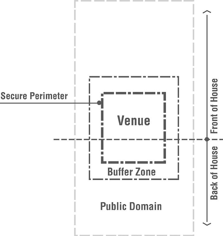
• Venue areas (Figure 71)
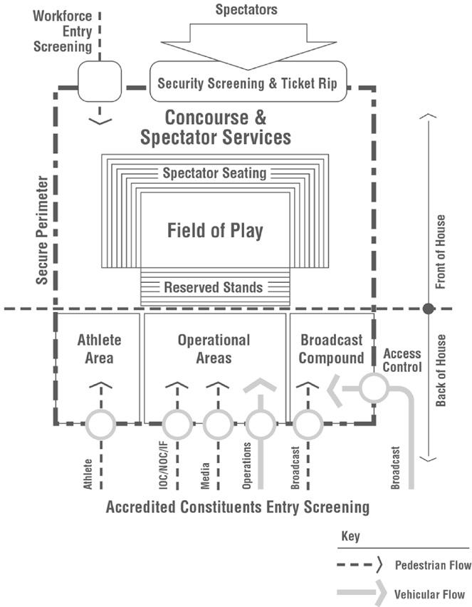
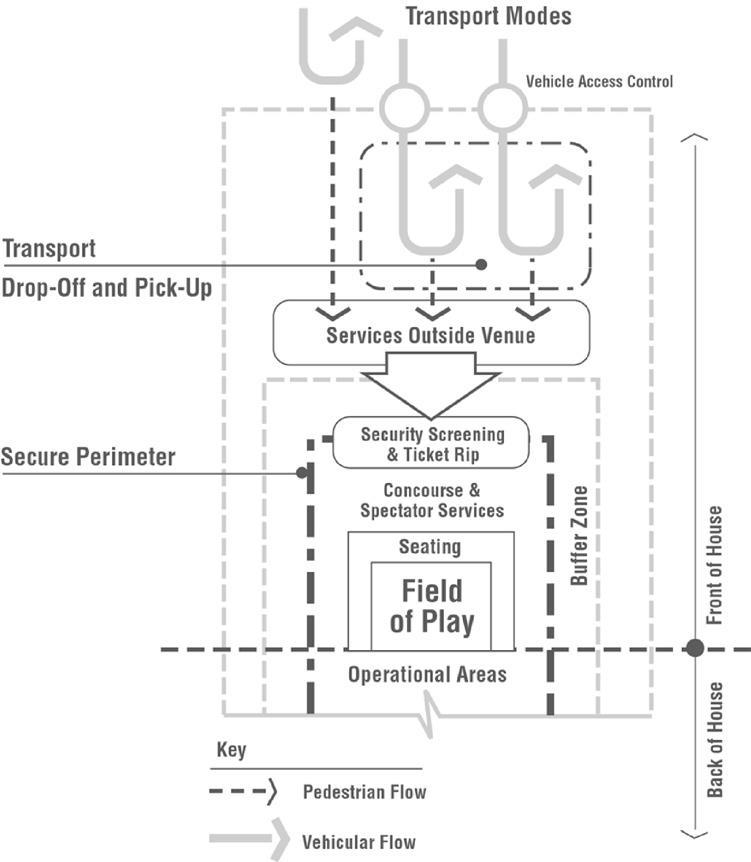
• Front of house operations (Figure 73)
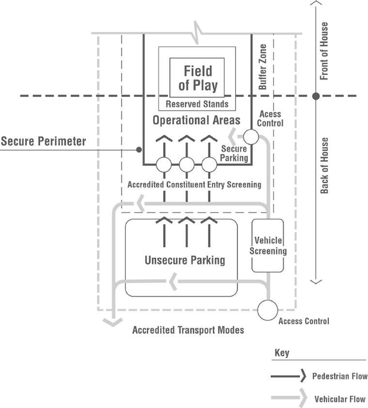
• Back of house operations (Figure 72)
• Seating and Standing Areas (Table 3)
• Venue interior (Figure 74)
• Safety of the venue (Table 1)
146
147
Figure 71. Venue Areas. Source: IOC Technical Manual on Design Standards for Competition venues, 2005
Figure 72. Back of house operations diagram. Source: IOC Technical Manual on Design Standards for Competition venues, 2005
Figure 73. Front of house operations diagram. Source: IOC Technical Manual on Design Standards for Competition venues, 2005
Figure 74. Interior venue diagram. Source: IOC Technical Manual on Design Standards for Competition venues,
Principles
Evacuation /Escape System
• Venue designs that change the layout may, in some circumstances, increase the safety requirements and the need for additional public assembly areas.
• In the case of an emergency, a rapid evacuation and dispersal of spectators may be necessary; therefore both permanent and temporary venue designs should have organized evacuation routes that have been integrated into the venue design.
• Plans for the existing facility should be considered along with the Olympic overlay that will be installed (e.g. tents, stands, trailers, fences).
• Evacuation plans for FOH (spectator areas) should be independent of the evacuation route used for BOH (Athletes, Olympic Family).
• Provisions should be developed for persons with accessibility needs (e.g. wheelchairs).
Emergency Vehicle
Access and Parking
• Vehicular access for the ambulance and emergency vehicles should be planned with pedestrian flows and efficiency in mind.
• Parking should be close to spectator areas and FOP with designated routes out of the venue.
• Helicopter landing pad and/or area may be necessary for certain venues.
Audio capability
Lighting
Fire Safety
• A public address system should be in place and available to communicate messages to all constituent groups if an emergency arises.
• A suitable level of lighting for required spaces and corridors or pathways.
• Sufficient backup emergency lighting for spaces/corridors/ pathways.
• An automatic alarm system should be installed in the facility.
• Fire extinguishing systems (portable and fixed) should be installed and distributed throughout the venue.
• Appropriate signage identifying safety equipment should be posted throughout the facility.
Lightning Strikes
• Design measures should take into consideration the risk of a potential direct or indirect lightning strike and proper precautionary steps should be incorporated into the venue and overlay.
148
Table 1. Principles for safety. Source: IOC Technical Manual on Design Standards for Competition venues, 2005.
Besides these general principles, the IOC Technical Manual sets some space standards necessary in Ice Hockey venues for the spectators, players, committees, and workers. Table 3 summarizes these spaces. It is important to notice that the design for Santa Giulia took into account these references, but also included new programmatic features, anticipating futures uses after the Olympics.
Seating and standing areas Principles
Minimum width
Minimum depth
• 46 centimetres (18 inches).
• USA - 61 centimetres (24 inches); not generally recommended.
• Europe - 80 centimetres (31.5 inches); recommended minimum.
Note: Temporary seating systems are usually 75 centimetres (29.5 inches) in depth and are generally accepted for use by local agencies.
Table 3. Ice Hockey Seating and standing areas principles. Source: IOC Technical Manual on Design Standards for Competition venues, 2005
venues design standards spaces and requirements. Source: IOC Technical Manual on Design Standards for Competition venues, 2005
Table 2.
149 Olympic Games Technical Manual on VenuesDesign Standards for Competition ICE HOCKEY 2 Space Gross Aream² Accreditation 164,00 Broadcast 3953,00 Catering 1020,00 Ceremonies 137,00 Cleaning and Waste 420,00 Doping Control 208,00 Event Services 194,00 Finance 72,00 Language Services 28,00 Logistics 1355,00 Medical Services 313,00 Merchandise 70,00 Olympic Family Services 560,00 Press Operations 1080,00 Security 1849,00 Sponsor Services 2575,00 International Federation 615,00 Sport Presentation 100,00 Technology Operations 122,00 Information Technology 60,00 Telecommunication & Audio Visual 198,00 Timing, Scoring and Results Operations 116,00 Technology Storage 110,00 Ticketing 100,00 Transport 1930,00 Venue Development 680,00 Venue Management 900,00 Total 20326,00
Ice Hockey 2
IIHF PROGRAM RECOMMENDATIONS
ACTIVITIES AND SERVICES
The IIHF (International Ice Hockey Federation sets some basic programmatic principles to follow when building an Ice Hockey venue. There is also an emphasis on the interest a community must have on the Ice rink venue to make it financially sustainable over time, That is why IIHF establishes that any Ice rink should be built under a “Sport for All” approach, promoting health and sociocultural development for a community. There is a latent need for round-the-year uses, turning the venues suitable for other uses in ice-free months. During the ice seasons, the venue owner should partner with the community, clubs, and schools, to keep activities on an 18h/day basis. It is important, therefore, to youth and adult programs, as well as mix hockey with other skating sports, like figure skating, short track, and curling. To target the youth and provide a medium and long-term perspective of users, it is important to set “Learn to Skate & Learn to Play Hockey” programs, which will allow the creation of a community of users in the future.
Public skate sessions, that is, the use of the general public for free skating for a fee are also recommended in a way to introduce new people to the ice rink venues and keep the schedule of an ice rink venue full.
THE SPATIAL PROGRAM NEEDED FOR ICE RINKS
The IIHF provides an ice rink guide establishing the technical and spatial requirements for an economically sustainable ice rink construction. Although using a small-scale example, the IIHF guide provides good guidelines for the program of an ice rink allied with the basic technical needs that building an ice rink requires.
150
151 Rooms m2 Ground floor 3,959.75 0 – 01 Ice pad 1,791.50 0 – 02 Main hall 795.80 0 – 03 Ice resurfer 47.00 0 – 04 Mechanical room (compressors) 45.50 0 – 05 Storage ( goals and short track) 36.30 0 – 06 Entrance 64.80 0 – 07 Ticketing, arena office & control area 23.60 0 – 08 Rental skates counter 26.90 0 – 09 Public skating dressing room 71.00 0 –10 Lobby 95.00 0 –11 Shop 26.60 0 –12 Stairs 20.20 0 –13 Lift 4.10 0 –14 Lavatory (disabled) 5.60 0 –15 Public skating lavatory female 13.00 0 –16 Public skating lavatory male 10.80 0 –17 Club office 40.60 0 –18 Staff locker room 14.70 0 –19 Corridor 171.65 0 – 20 Medical/ first aid room 16.35 0 – 21 Skates and maintenance room 15.90 0 – 22 Electrical control room 4.15 0 – 23 Fire extinguish room 12.10 0 – 24 Plumbing room 10.80 0 – 25 Drying rooms (11 un) 102.55 0 – 26 Figure skating storage room 12.85 0 – 27 Figure skating coaches room 17.60 0 – 28 Laundry & cleaning room 6.20 0 – 29 Inner stairs 13.55 0 – 30 Ice hockey equipment room 15.05 0 – 31 Dressing room hockey 1 43.50 0 – 32 Showers & lavatory hockey 1 19.30 0 – 33 Showers & lavatory hockey 2 19.30 0 – 34 Dressing room hockey 2 42.00 0 – 35 Dressing room hockey home team 48.45 0 – 36 Showers & lavatory hockey home team 20.90 0 – 37 Dressing room referees 20.80 0 – 38 Dressing room hockey coaches 20.80 0 – 39 Showers & lavatory hockey visitor team 20.95 0 – 40 Dressing room hockey visitor team 49.00 0 – 41 Dressing room figure skating male 42.10 0 – 42 Showers & lavatory figure skating male 19.30 0 – 43 Showers & lavatory figure skating female 19.30 0 – 44 Dressing room female figure skating 42.30 Rooms m2 Ground floor 3,959.75 0 – 01 Ice pad 1,791.50 0 – 02 Main hall 795.80 0 – 03 Ice resurfer 47.00 0 – 04 Mechanical room (compressors) 45.50 0 – 05 Storage ( goals and short track) 36.30 0 – 06 Entrance 64.80 0 – 07 Ticketing, arena office & control area 23.60 0 – 08 Rental skates counter 26.90 0 – 09 Public skating dressing room 71.00 0 –10 Lobby 95.00 0 –11 Shop 26.60 0 –12 Stairs 20.20 0 –13 Lift 4.10 0 –14 Lavatory (disabled) 5.60 0 –15 Public skating lavatory female 13.00 0 –16 Public skating lavatory male 10.80 0 –17 Club office 40.60 0 –18 Staff locker room 14.70 0 –19 Corridor 171.65 0 – 20 Medical/ first aid room 16.35 0 – 21 Skates and maintenance room 15.90 0 – 22 Electrical control room 4.15 0 – 23 Fire extinguish room 12.10 0 – 24 Plumbing room 10.80 0 – 25 Drying rooms (11 un) 102.55 0 – 26 Figure skating storage room 12.85 0 – 27 Figure skating coaches room 17.60 0 – 28 Laundry & cleaning room 6.20 0 – 29 Inner stairs 13.55 Ice hockey equipment room
Figure 75. IIHF Basic Requirements for an Ice rink, groundfloor.
Source: IIHF Ice rink guide, 2018
152 Rooms m2 First floor 1,239.05 1– 01 Terrace 36.95 1– 02 Smoking area 9.30 1– 03 Restaurant 92.65 1– 04 Café 48.10 1– 05 Kitchen 30.95 1– 06 Vip box 23.05 1– 07 Game supervisor & timing box 20.55 1– 08 Stairs 20.20 1– 09 Lift 4.40 1–10 Spectators lobby 76.30 1–11 Lavatory (disabled) 5.60 1–12 Spectators lavatory male 21.20 1–13 Spectators lavatory female 24.40 1–14 Restaurant storage 5.50 1–15 Team meating room 30.45 1–16 Corridor 70.95 1–17 Under seats zone (height minus 2,50) 279.15 1–18 Spectators passage 168.35 1–19 Figure skating office 19.00 1– 20 Short track office 19.00 1– 21 Ice hockey office 19.00 1– 22 Vip reception & catering room 39.40 1– 23 Inner stairs 12.05 1– 24 Gym 22.90 1– 25 Warm-up & streching zone 114.00 1– 25 Mechanical room (air) 21.30 Rooms m2 First floor 1,239.05 1– 01 Terrace 36.95 1– 02 Smoking area 9.30 1– 03 Restaurant 92.65 1– 04 Café 48.10 1– 05 Kitchen 30.95 1– 06 Vip box 23.05 1– 07 Game supervisor & timing box 20.55 1– 08 Stairs 20.20 1– 09 Lift 4.40 1–10 Spectators lobby 76.30 1–11 Lavatory (disabled) 5.60 1–12 Spectators lavatory male 21.20 1–13 Spectators lavatory female 24.40 1–14 Restaurant storage 5.50 1–15 Team meating room 30.45 1–16 Corridor 70.95 1–17 Under seats zone (height minus 2,50) 279.15 1–18 Spectators passage 168.35 1–19 Figure skating office 19.00 1– 20 Short track office 19.00 1– 21 Ice hockey office 19.00 1– 22 Vip reception & catering room 39.40 1– 23 Inner stairs 12.05 1– 24 Gym 22.90 1– 25 Warm-up & streching zone 114.00 1– 25 Mechanical room (air) 21.30 1– 26 Cleaning room 4.35 Second floor 749.94 2 – 01 Emergency exit zone 147.40 2 – 02 Spectators zone 602.54
Figure 76. IIHF Basic Requierments for an Ice rink, groundfloor.
Source: IIHF Ice rink guide, 2018
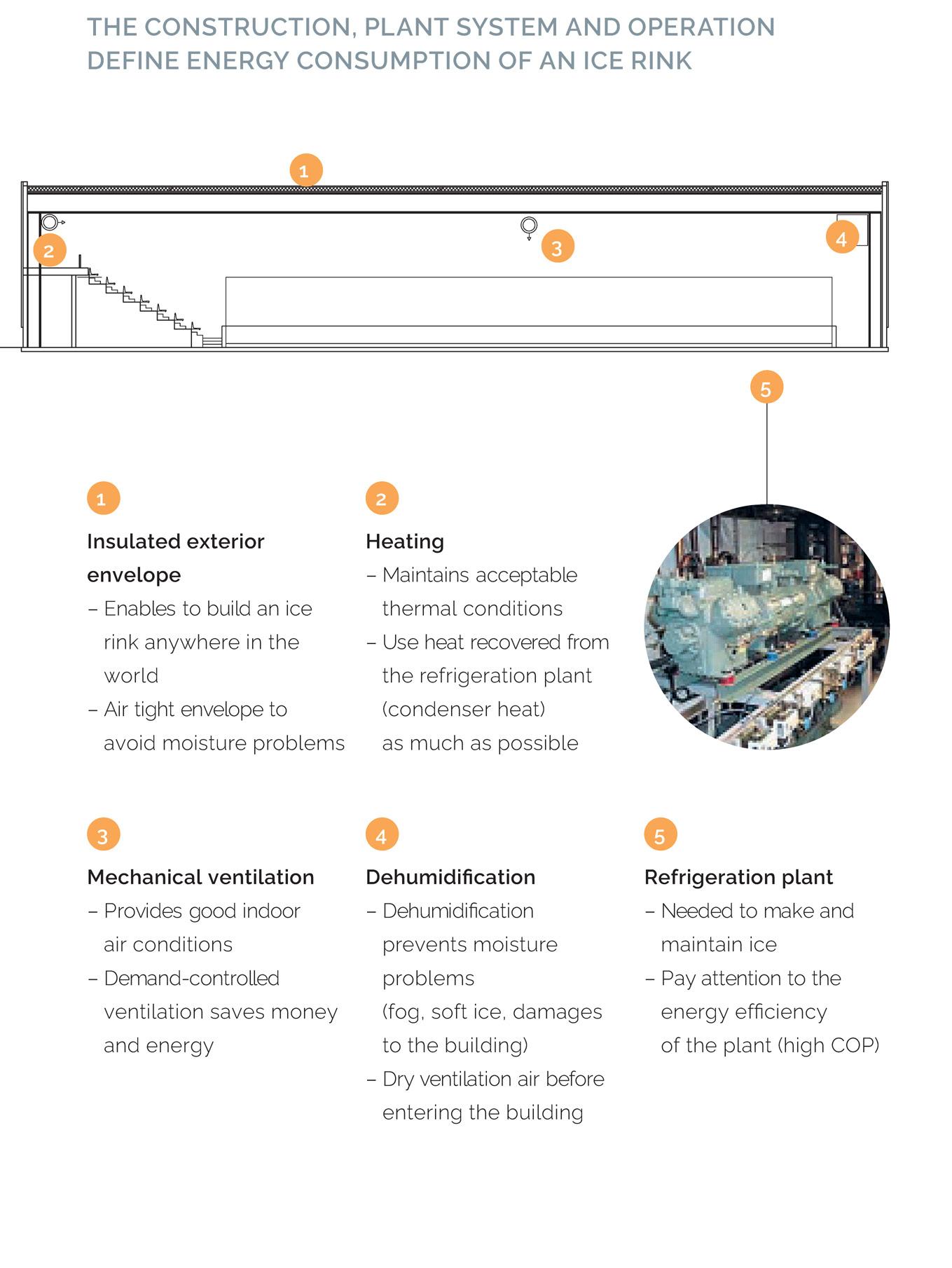
The space descriptions presented in Table 4 and Table 5 was used as a reference for the spatial distribution for the proposal in Santa Giulia. Figure 75 and Figure 76 exemplify a basic project for an Ice rink of small dimensions but set an important organization that was a start point for our proposition. Finally, some technical aspects also are influent in the characterizations of our program. Figure 77schematically represents these basic needs.
153
Figure 77. IIHF Basic technical requirements for Ice rinks. Source: IIHF Ice rink guide, 2018
PROGRAM
BUILDING PROGRAM DISTRIBUTION
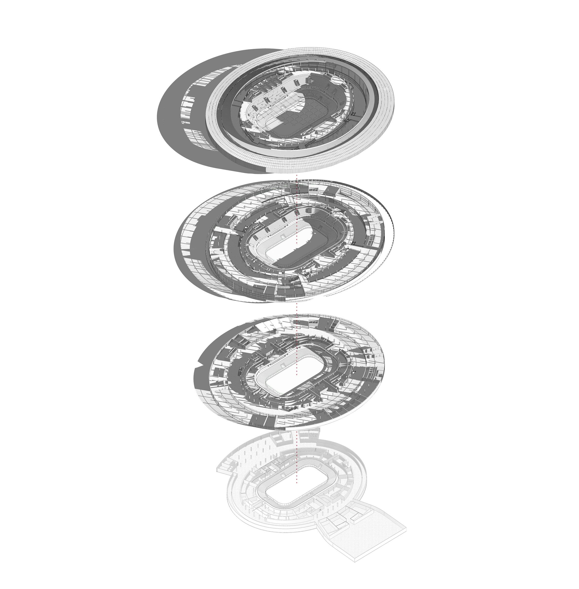
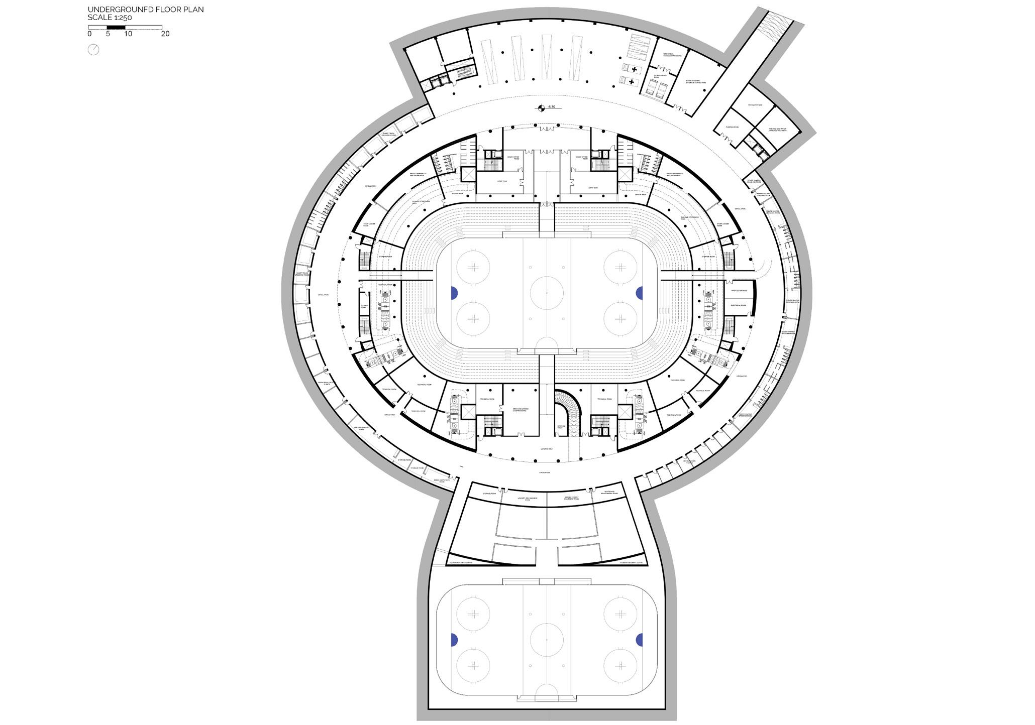
After analyzing the architectural references and the technical constraints, the distribution of the functions around the building follows some basic principles: splitting the flows of people, “hiding” the technicals, splitting the everyday use from the event-day use. That is why, in general, on the underground and -2 level floor, all the technicals and access to staff and players was located, while we find on the ground floor the uses for the community and spectators and the last floor is dedicated to the VIP areas.
154
Figure 78. Building Program distribution. Source: Authors.
VIP
Seats
Supporters functions
Community functions
Seats
Supporters functions
Community functions
Seats
Garage/Access
Players functions
Support
Technicals
Ice rink
Elevation system
155
2nd Floor Seats
-2
Underground floor
1st Floor Ground floor
Floor
ARCHITECTURAL DRAWINGS
157
TOUCHDOWN
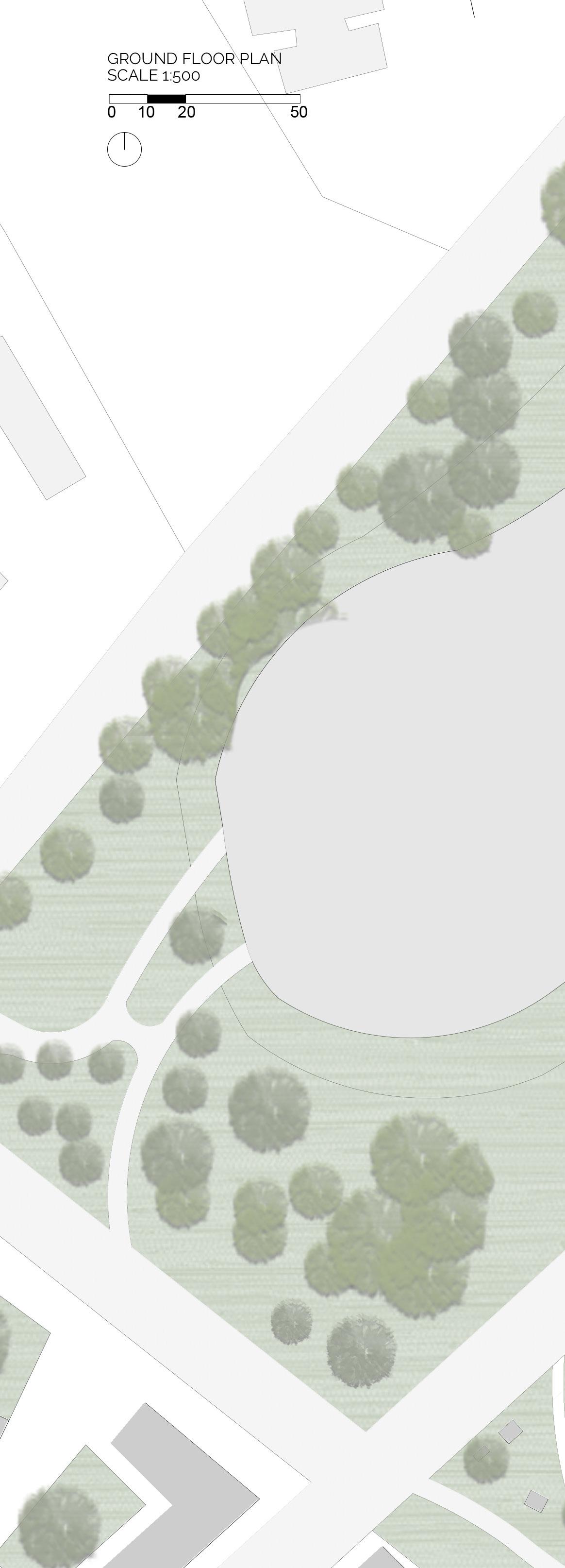
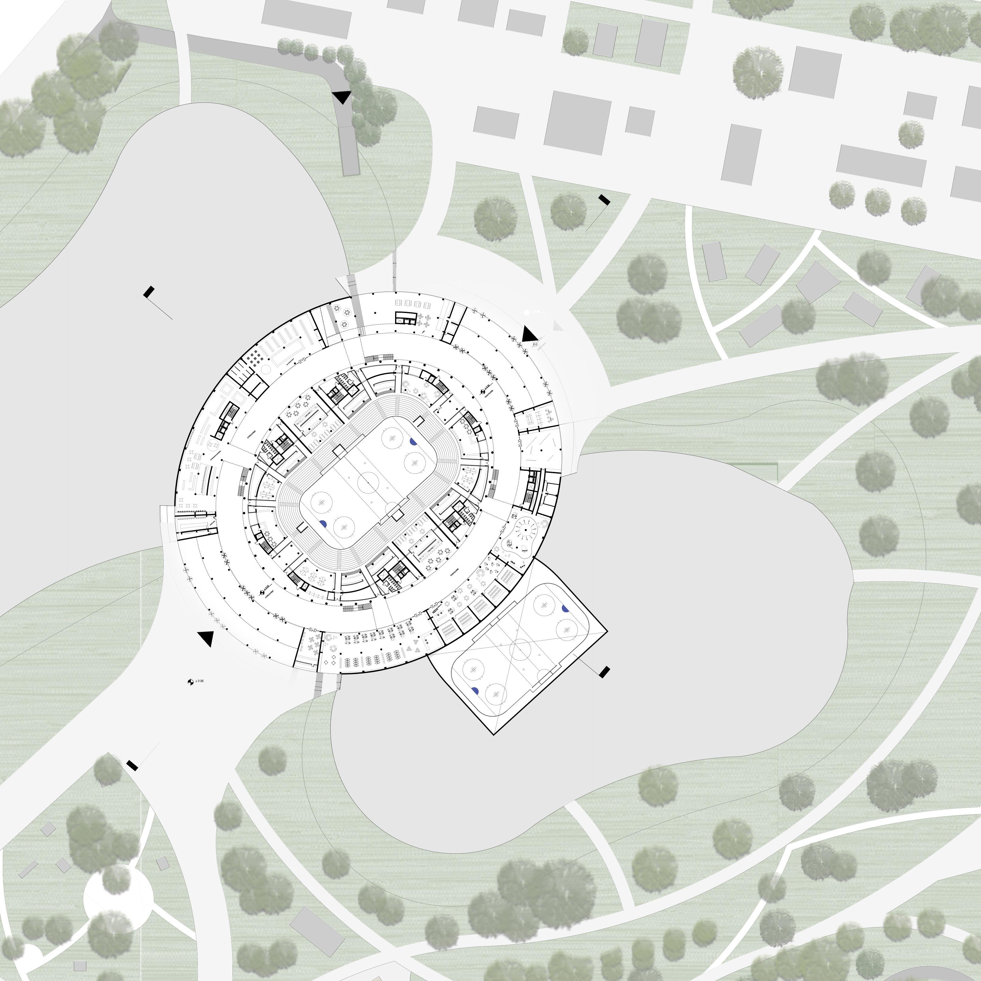
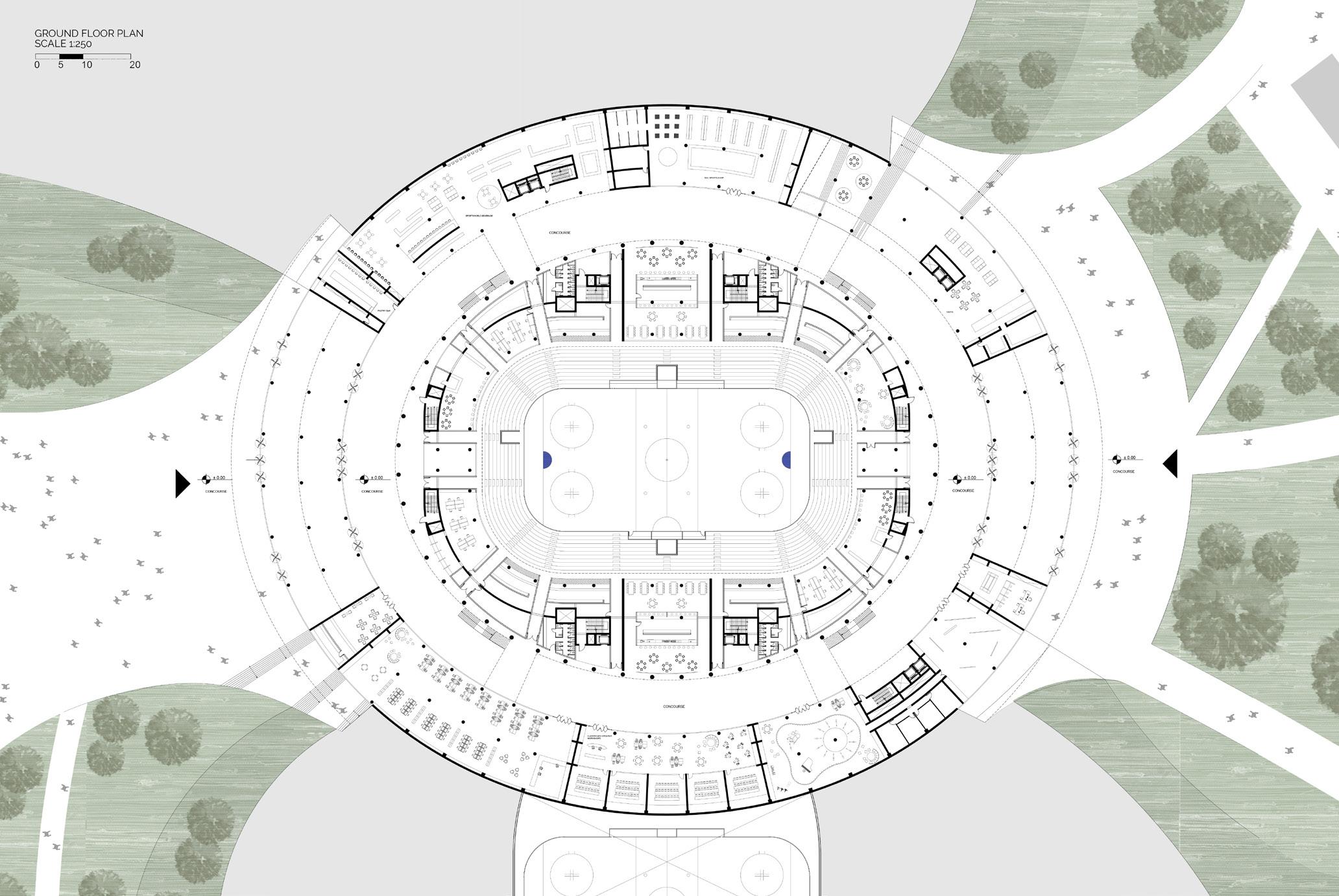
GROUND FLOOR LEVEL AND CONNECTION WITH SURROUNDINGS
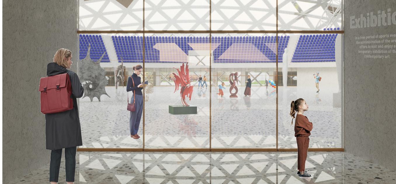
The experience begins with the ground floor connection, where the hierarchy of the entrances are defined with large scale squares in fron tof them. The squares offers various circulation solutions to experience the sport hall, whether a ground floor acces or a ramp or a stair leading to the first level. The wide long boulevard of Santa Giulia expands into this piazza and leads to the interior side, where various functions are located all around the perimeter, functions of different facilities such as commercial use but most importantly community use. The whole concept of our sport hall is for it be functioning all year long; thus, spaces such as markets, workshops, library, dance school, music hall, exposition, and restaurants, are all located on our main gateaway floor.
The intermediate ring, the gallery, serves the functions on both sides and leads to the entrances of our stadium, with various doors and accesses are provided along the elipse, where fans will be directed to their corresponding entrance and access their seat.
158
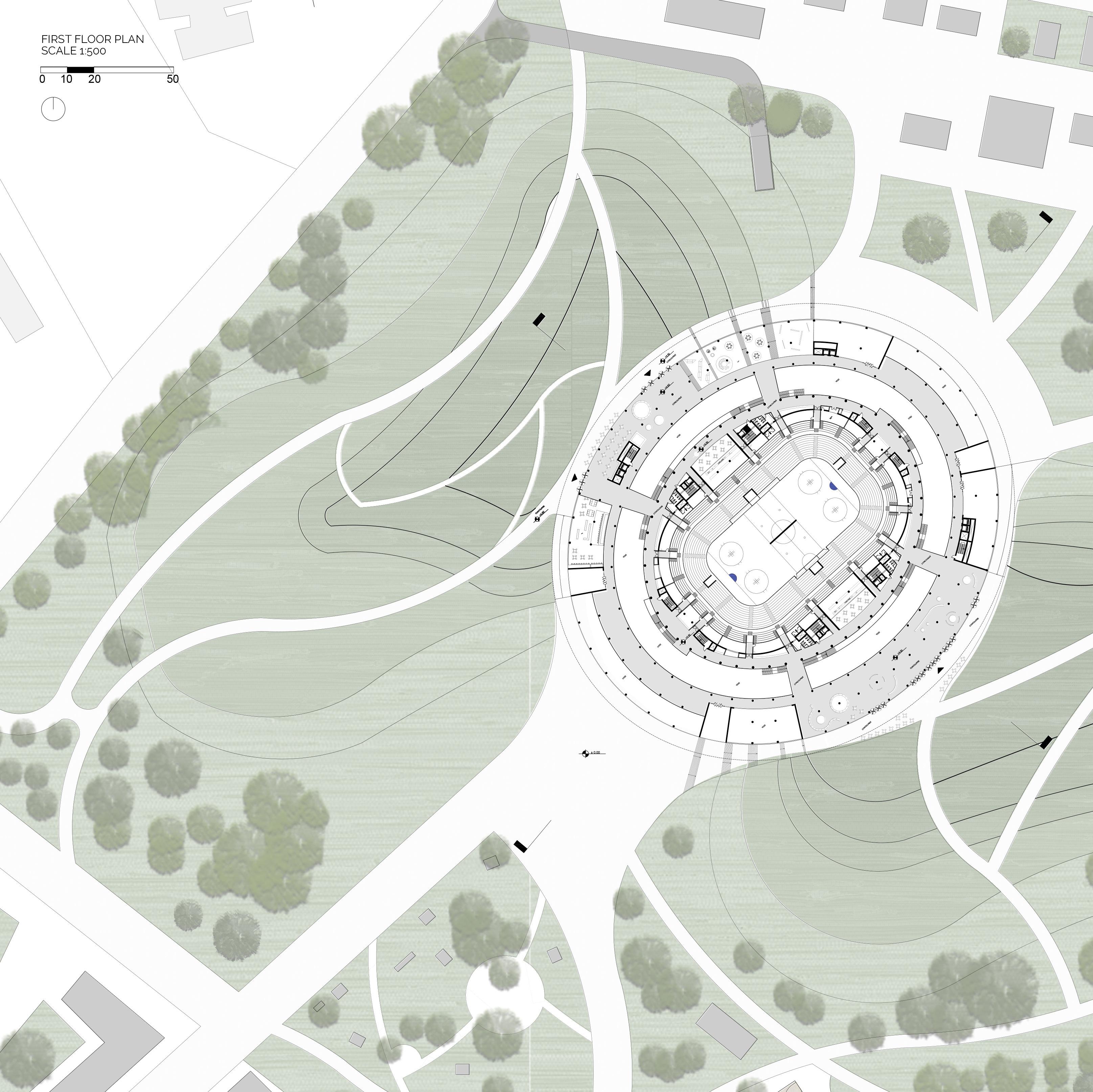
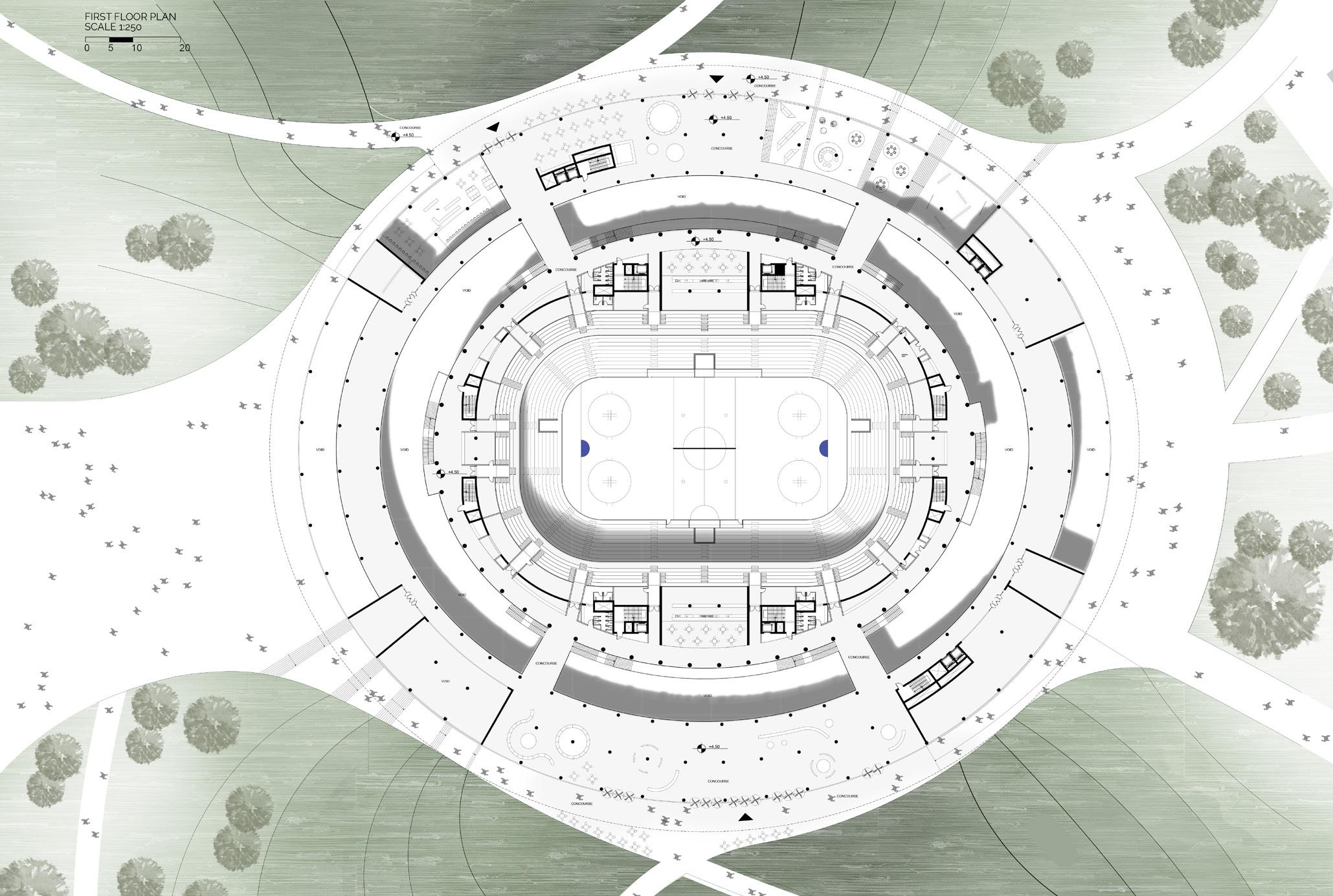
A HIGHER EXPERIENCE
FIRST FLOOR LEVEL AND DIFFERENT VISUALITIES
Another access into the sport hall can be through the upper platforms, an evenly intersting access, where people will have to walk along a green promenade through a man-made green hill, made of the excavated soil during the construction process. These pathways, with their organic shapes, drive the person along the hill into the buildings, where he or she will directly experience a well lighted interior spaces with natural lights, through the glazed roofs. On such level, the platforms play a visual relation role, in which different voids and bridges are placed, leading to different areas and levels. An esplanade is placed on the side of one of the entrances, while a restaurant is placed on the other side with an exterior extension for a better outdoor experience overlooking the park.
To access the seats through this level, one will have to walk through the bridges designed, and access their corresponding door, or if needed, take the parallel stairs to reach their desired level.
161
162
163
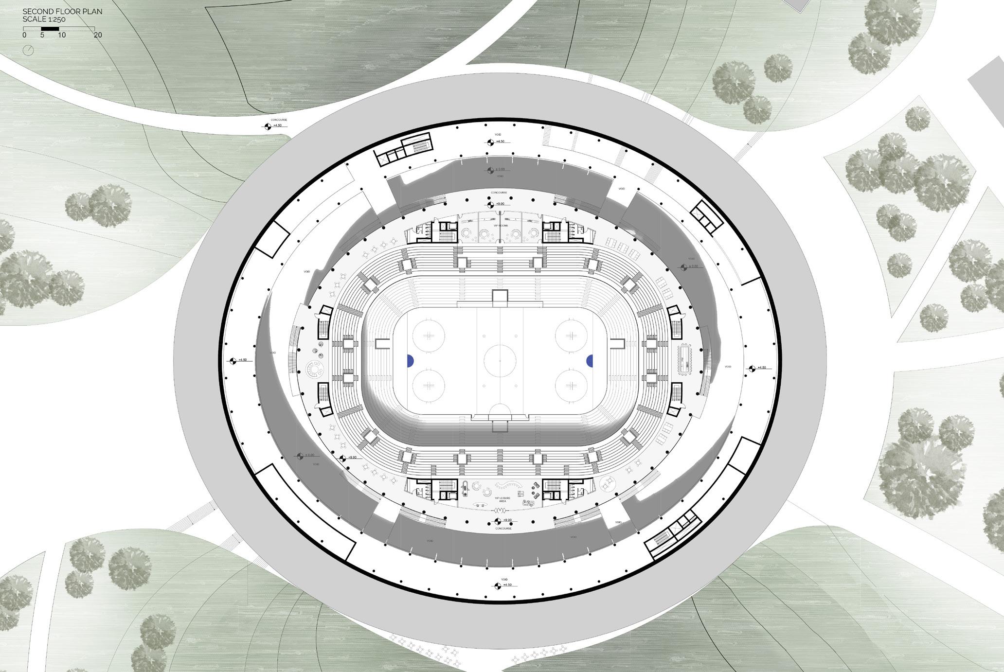
SECOND FLOOR
164
165
In an attempt to design a sustainable and multifunctional sports arena, which functions on a daily basis, having the ability to host different functions, a system of modular and variant seating was applied.
In such aspect, different sports activities can take place, through the retracting or expanding of the seatings, giving a closer ambiance to the field through lowering the field level itself.

Such different scenarios can benefit the sport arena socially, culturally, and economically while hosting also larger events and expositions through lifting the field up to zero level and relying on the fixed seats of the first level.

167