ACompositeMonolith B.Arch 2018 DIMITRI CUNSIR
Form and Material Expression
This thesis is explored through the world of concrete and how it forms, function and materiality is expressed in architecture.
Is it Stone? Yes and No.
Is it Plaster? Yes and No.
Is it Brick or Tile? Yes and No.
Is it Cast Iron? Yes and No.
Poor Concrete! Still looking for its own at the hands of Man.
(Wright, 1928)Concrete is an ambiguous and versatile material and is one of the predominant building material in today's constructions industry. The field of concrete is vast and complicated, in this thesis I will research how concretes production process express the form function and materiality in architecture.
This Thesis explores how concrete and its production process, in particular precast, cast in situ and the modular block come together to create a composite monolith. The composite monolith refers to the structure which constructed from the same material and creates a sense of unity and composition within the structure. The beauty of concrete as a monolithic material lies within its artificiality and the ambiguity to be expressed and constructed in a range of techniques and process.
In architecture ''Distribution'' refers to the movement of people, services and goods within the built environment.
This unit was focused on distribution not only within a building or the site boundary but also distribution as a broader element of the urban environment. The move ment of services, goods and people is the main focus within this thesis and design Project.
Circulation, transportations and movement of people is the main aspect of the distribution which is analyzed in this thesis.
In Ireland and Dublin area.
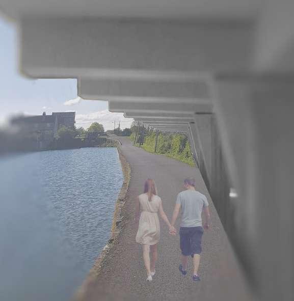
The canals and railways in Ireland and in particular in the Dublin area, both historically and in the present day have a great impact on the circulation, transportation and the movement of people, and the development of the urban fabric.
The Royal Canal initially created the link between Dublin and the rest of the country and then the railways followed soon after. The canals and railways have a close relationship, due to the nature of the canals and the necessity of relatively flat ground for the flow of water and movement of goods. This allowed for the spread of railways and infrastructure alongside the canals through Ireland, Fig.1.1 represents the close proximity between the canals and railways of Ireland.
Fig. 1.1 Railways and Navigational Waters Ireland 2015 Fig. 1.2 Railways Ireland 1905 Fig. 1.3 Railways Ireland 2015 Fig. 1.4 Royal Canal and Railways Ireland 2015 Fig. 1.5 Infrastructural Development Canals and Railways Dublin 1840 Fig. 1.6 Infrastructural Development Canals and Railways Dublin 1910 Fig. 1.7 Infrastructural Development Canals and Railways Dublin1965 Fig. 1.8 Infrastructural Development Canals and Railways Dublin 2015The site is located alongside the Royal canal in Phibsboro between the lock 4 and 5. the site is located above the intersecting railway lines that connect the Docklands Train Station to M3 Parkway Train Station and Connolly Train Station to Mullingar Train station. the site is also located on the main road that connects Phibsboro with Finglas.
The site faces many problems, including isolation from the main road, railway penetration and a sheer drop in level from ground level to the rail line level, the adjacent Royal Canal minimizes the possibility for underground excavation dues to the retention of the canal water.
The site is located in one of the busiest intersections in Phibsboro, both at street level and underground at the railway level the site is exposed to a large amount of traffic.
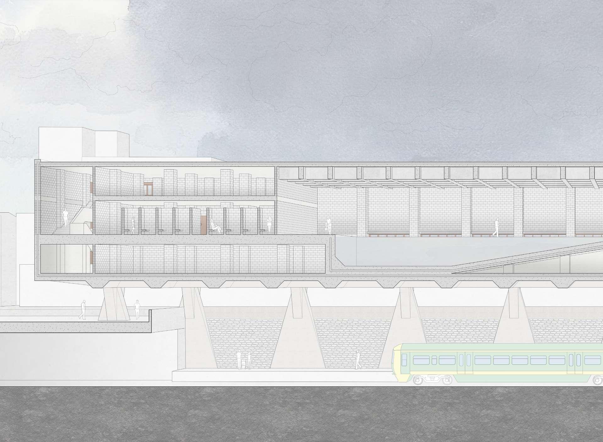
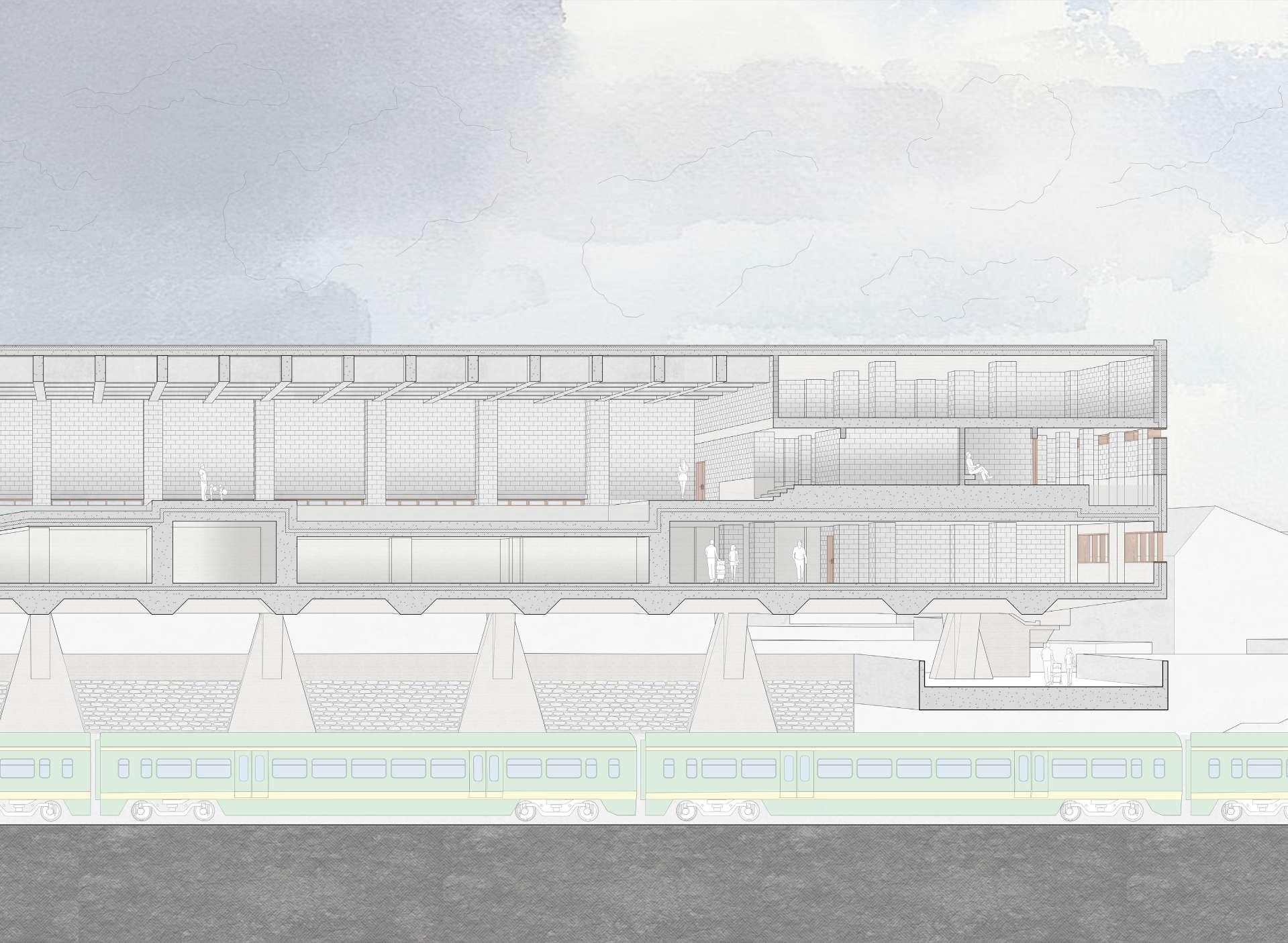
The brief selected for this specific site is composed of two elements, an underground train Station that facilitates the intersecting railway lines and a leisure center elevated above the train station and ground level.
The train station will introduce a new stop on the existing railway routes and will act as a new focal point in Phibsboro, the proposed train station will aid in the reduction of traffic and conjecture in the area .
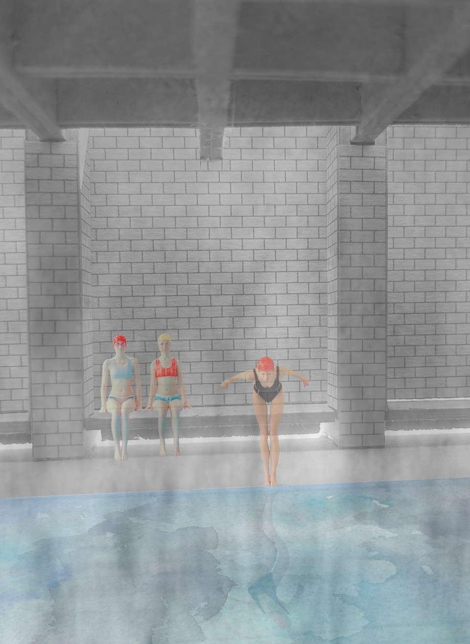
The leisure center consists of a swimming pool and a new gym with all the necessary amenities. Due to the nature of the site the leisure center will be located directly over the railway lines and new train station.
The two elements of the brief would work in conjunction with each other, the new train station will accommodate both for the access to the Phibsboro area and to the new leisure center, the leisure center will create a dentition for the commuters, the train station could also act as a pit stop, allowing the commuters to use the local services and the new leisure center.
-Four new platforms to accommodate the existing rail lines
-Multiple access to the platform from the ground level to accommodate queuing and meeting-greeting activities
-Large space for fare and Collection area
-Depth below ground level: 6 metres
-Platforms Length: 100 metres
-Vast open spaces on the ground floor to accommodate large gatherings.
-Swimming pool and Learners pool
-Communal changing rooms (cubicles) and Family (group) Changing rooms
-Communal showers (cubicles) and individual shower rooms
-Public toilets
-Offices, Sick bay, Offices, Staff changing rooms, Staff Room, Lifeguard office
-Spa room, Sauna, Steam Room, Jacuzzi, Chill Room, Massage Room
-Main entrance lobby, Reception desk, Cafeteria
-Storage, Boiler room, Electric generator, electrical Panel, Air conditioner room, Sterilizer, irrigation tank room, compensation tank
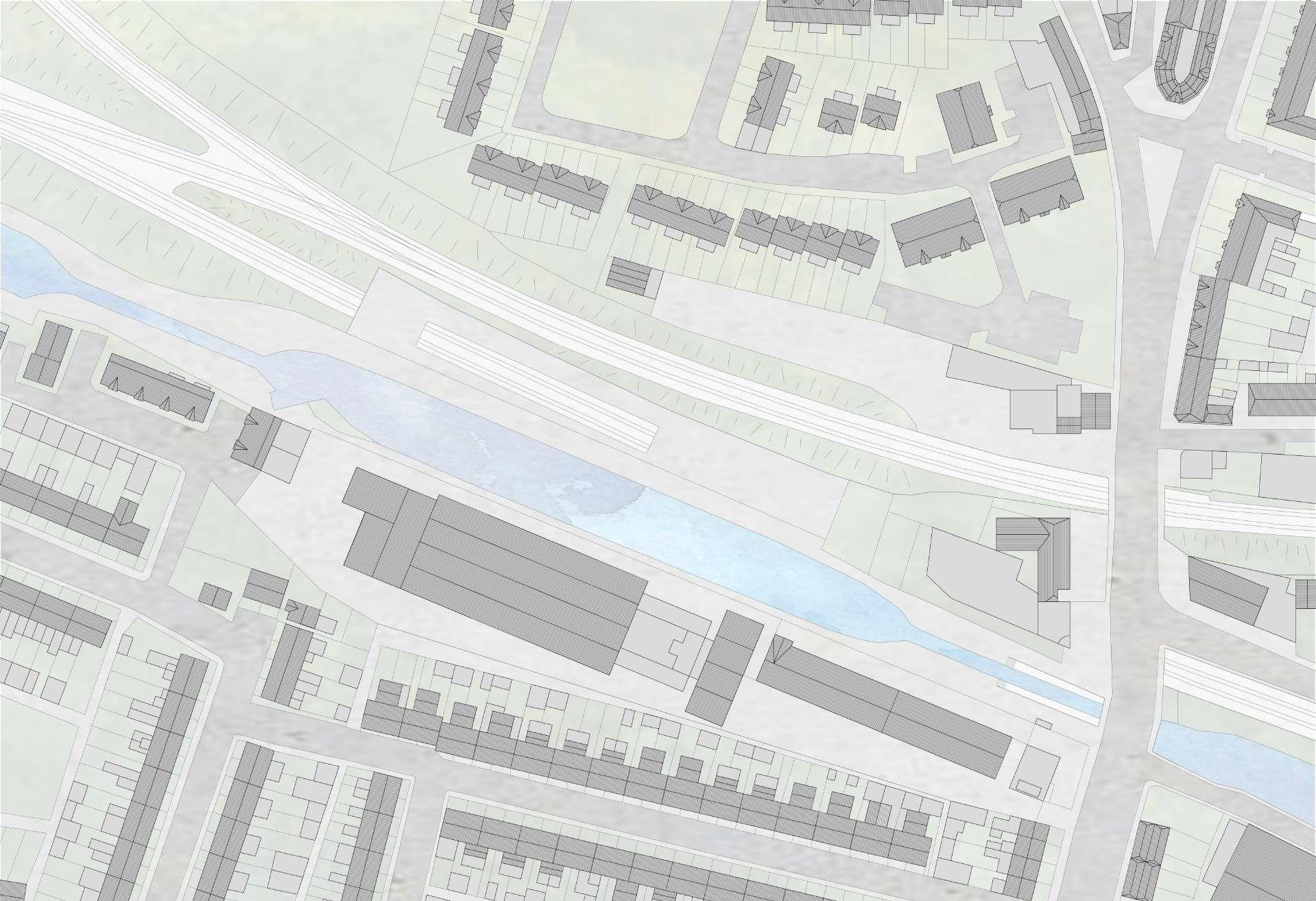 Fig. 2.3
Existing Site Plan Cross Gun Bridge Dublin
Fig.
Fig. 2.3
Existing Site Plan Cross Gun Bridge Dublin
Fig.
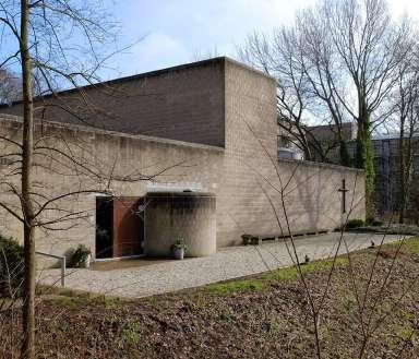
Architect: Peter Zumthor
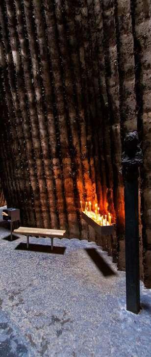
Year: 2007
Location: Mechernich, Eifel, Germany
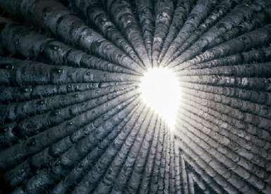
The building is an irregular pentagonal shape with 24 clearly visible daily joins and reinforcing rods, created by casting 24 layers of concrete each day, the interior is a kind of wigwam shape created by joining 112 pine trees as sacrificial shuttering and then slowly burned out to expose the negative of the pine tree. The reinforcing rods that joined the internal pine trees shuttering with the external shuttering were removed and the holes taped with glass marbles.
She structure is clearly expressed in the making of the chapel, both the external and the internal shuttering and the daily joints are expressed to manifest the materiality of the cast in situ concrete.
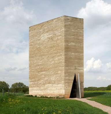 Fig. 3.4 Cast in situ Concrete Sectional Analysis
Fig. 3.1 Bruder Klaus Field Chapel
Fig. 3.2 Bruder Klaus Field Chapel
Fig. 3.3 Bruder Klaus Field Chapel
Fig. 3.5
Daily Joints Cast in situ Concrete
Fig. 3.4 Cast in situ Concrete Sectional Analysis
Fig. 3.1 Bruder Klaus Field Chapel
Fig. 3.2 Bruder Klaus Field Chapel
Fig. 3.3 Bruder Klaus Field Chapel
Fig. 3.5
Daily Joints Cast in situ Concrete
Architect: Louis Kahn
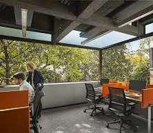
Year: 1965
Location: Hamilton Walk, University of Pennsylvania, Usa
The building consists of three main towers attached in a pinwheel formation. Each tower is supported by eight external columns, the structure consists of 1019 presented prefabricated concrete components that were fabricated off site then craned in position, this allowed for a fast and elaborate construction.
The composition of the structural elements was carefully designed to come tougher as a puzzle and the same elements are repeated and reused through the building, this allowed for a universality of the structure and spaces. The prestressed precast concrete beams, columns and trusses are left exposed to express the structure.
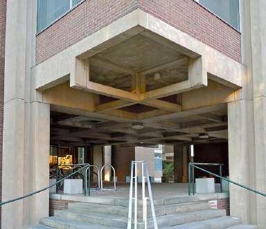 Fig. 3.9
Precast
Structural Analysis
Fig. 3.6
Richards Medical Research Laboratories
Fig. 3.9
Precast
Structural Analysis
Fig. 3.6
Richards Medical Research Laboratories
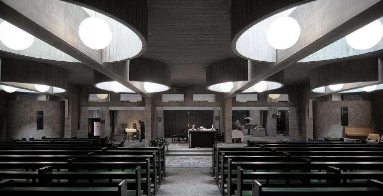
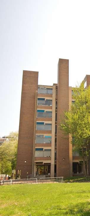
Architect: Aldo van Eyck
Year:1966
Location: Amsterdam, The Netherlands
The building is a rectangular shaped with two partitions extruded upwards, the linearity of the structure consists through and allows the manifestations of the materiality,lights and texture both externally and internally. The simplified shaped allows for the pure expression of the concrete block which is the predominant building material throughout the building.
Structural composition is based around the compression quality of a concrete blockwork walls and the span of a precast beam, the simplified structural system is deliberately expressed and allows for light and materiality to be expressed.
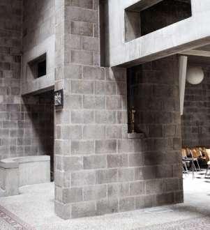 Fig. 3.14 Blockwork External Analysis
Fig. 3.11 Roman Catholic Church. The Hague
Fig. 3.12 Roman Catholic Church. The Hague
Fig. 3.13 Roman Catholic Church. The Hague
Fig. 3.14 Blockwork External Analysis
Fig. 3.11 Roman Catholic Church. The Hague
Fig. 3.12 Roman Catholic Church. The Hague
Fig. 3.13 Roman Catholic Church. The Hague
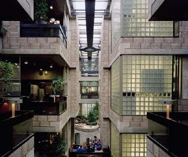
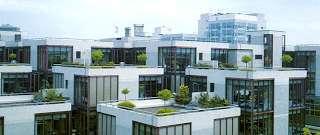
Architect: Herman Hertzberger
Year:1972
Location: Prins Willem-Alexanderlaan, The Netherlands
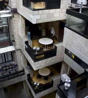
The building consists of 56 cube-shaped elements which are nine by nine meters, all under the same roof which allows for an anti-hierarchical structure on consists of open spaces with extruded voids.
The structural composition of the building consists of large cast in situ pile foundation elevated off the ground allowing for an underground carpark. The precast floor slabs sit on the capping of the pile foundation stretching from pile to pile. The building is a composite monolith, meaning its entirely constructed out concrete. The foundation and primary structure is cast in situ concrete, the structural floor slabs and columns are pre cast and the walls are concrete blockwork.
Fig. 3.19 Structural Composite Monolith Analysis Fig. 3.16 Centraal Beheer Offices Fig. 3.17 Centraal Beheer Offices Fig. 3.18 Centraal Beheer Offices Fig. 3.20 Composite Monolith Structural AssemblyThe Design process began by investigating the existing site and the implementa tion of the set brief upon.
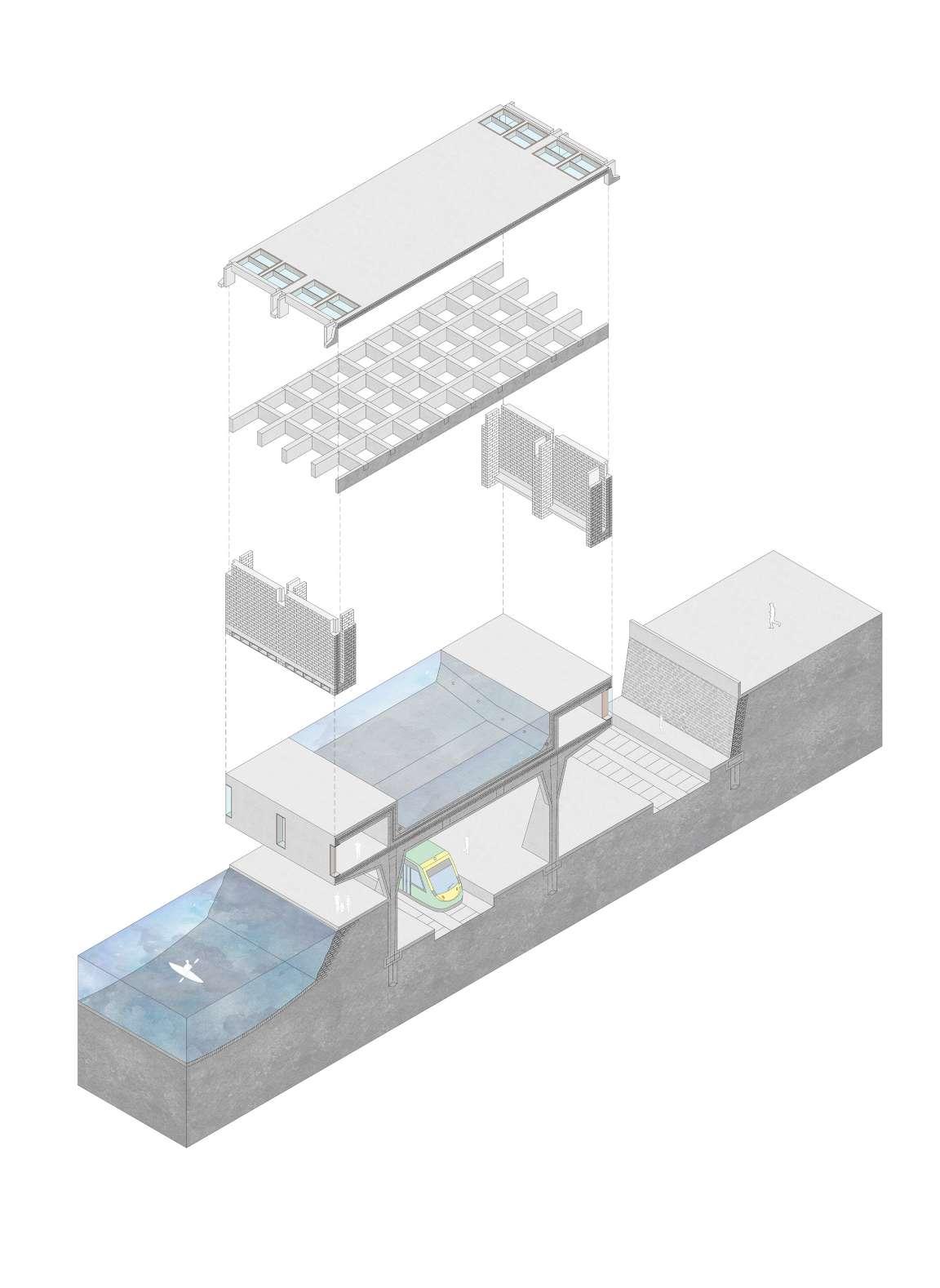
Dues to the nature of the site and the program, the design of the railway station and the Leisure venter above became a homogenous structure which is separated into three parts: the cast in place retaining walls, and the swimming pool basin be come one continuous structure, the concrete blockwork enculture of the swimming pool and all the necessary necessary amenities and the structural roof system. Each of the three elements expressed the construction process by expressing the form function and materiality.
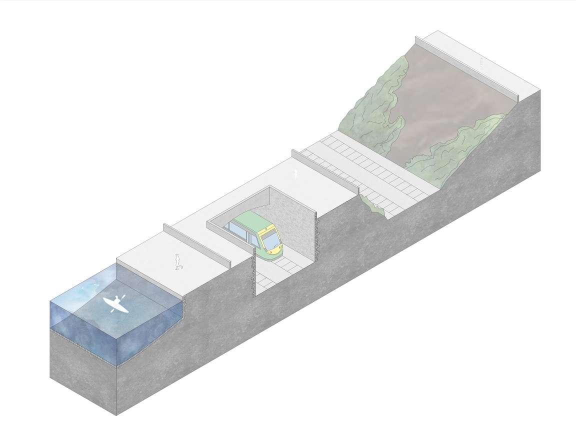
Within the cast in place concrete stratum the types of concrete and the process varied in regards to the task undertaken. the Retaliation of ground and water was achieved by casting jute bags and creating a seal to prevent the leakage of water, the shuttering used for the structural columns that supported the swimming pool a reusable casing was used to create a homogenous system.
The concrete block expressed through the compression as the internal colonnade that supported the roof, the offset from the exterior wall allowed for the structure to be free from the outer skin of the building this way creating interesting moments with light and texture.
The precast concrete roof allowed for homogenous structure that was replicated over and over to create a cellular frame for the roof.
The design process of this begin thrived to create a composite monolith which would express each construction process through its form function and materiality.
Fig. 4.1 Existing Site FabricThe design of how the Station and the Leisure center was to be constructed began by researching the process of how each concrete type is constructed.
Leading from the three experimental projects carried out in first semester I then further investigated how cast in situ, precast and the modular concrete block are utilized in the construction industry.
By understanding the material properties and qualities I then began to set a num ber of rules that would allow for each component to be fully expressed thought its form function and materiality.
Due to the nature of the proposed site and building cast in situ concrete had to deal with the retention of ground and water, the concrete block with enclosure of spaces and the precast with span and connection.
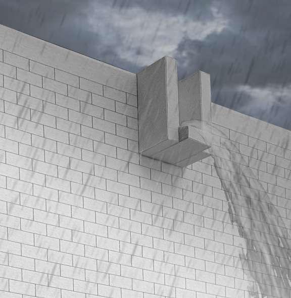
The proposed building is excavated underground and then elevated above the ground floor accommodating for the Railway platforms and a swimming pool above. Cast in place concrete retaining walls in particular Artisanal Quay Walls which are jute bags filled with concrete and allowed to set layering a sealed membrane that retains ground and moisture, having the Royal canal on one embankment and the retention of ground on the other this type of Quay Wall was very affective. Cast in place concrete is also used in the structural columns and the basin of the swim ming pool which is elevated the off the ground level.
The concrete block is great in compression and is a modular member that can be assembled rapidly, this type of concrete was chose to deal with concealment and enclosure, it also creates a colonnade internally that supports the roof.
Precast prestressed concrete is used in the roof where the span necessitates a lon ger distance than normally, this type of concrete production is ideal for large spans as it can be manufactured offsite assembled in position once the rest of the build ing is done, this type of construction also allows for repetitions of the same ember to achieve a composite structure, which is significantly stronger than its individual member. meber to achieve a composite structure, whicj is significantly strobger than its indiviual memebr.
Fig. 4.2 Proposed Site Strategy and Construction Process Fig. 4.3 Artisanal Quay Wall Fig. 4.4 Precast Concrete Block Quay Wall Fig. 4.5 Steel Sheet Piled Quay Wall Fig. 4.6 Caisson Quay Walls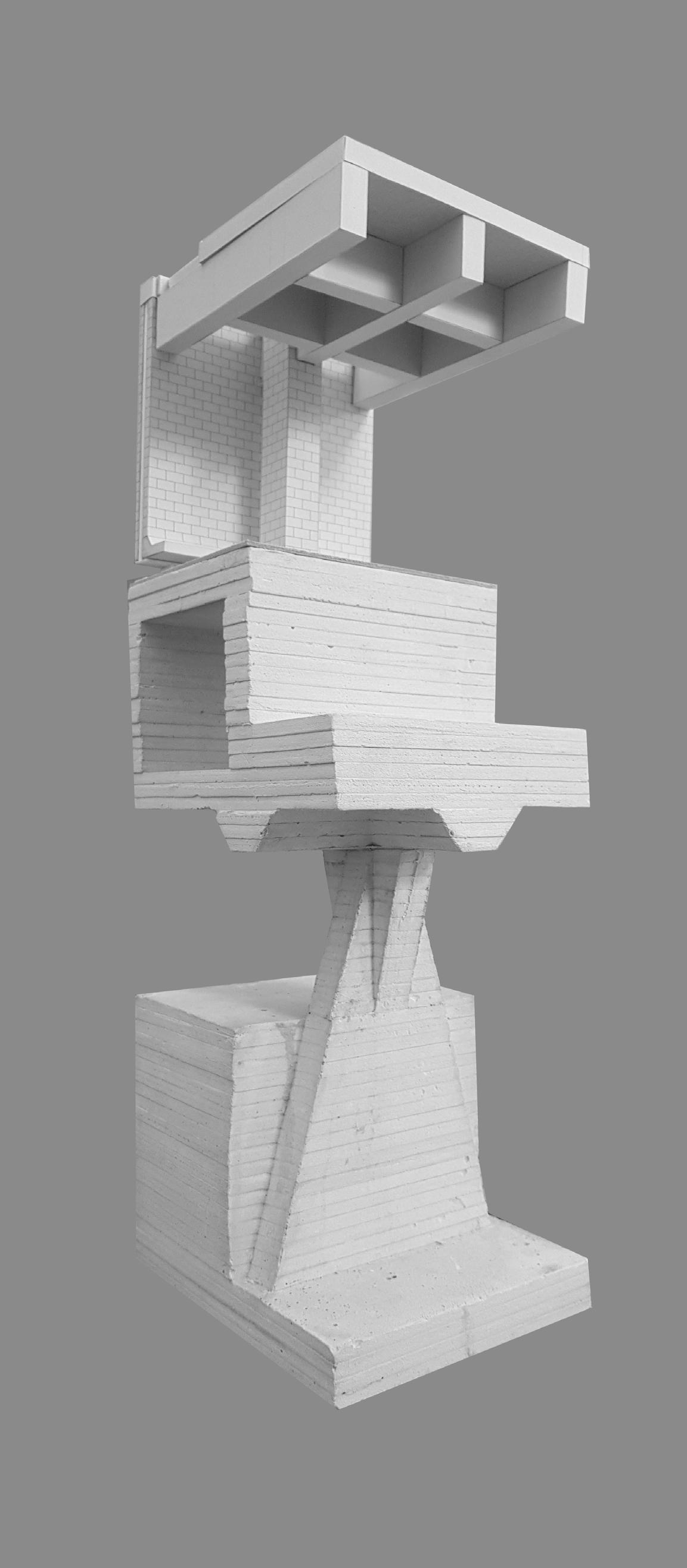
The final design aims to express the aesthetic and atmospheric possibilities of concrete and it production process.
The final building is a composite monolith consisting entirely out of concrete. Through the building concrete is used to explore certain characteristics of its qual itative and quantitively properties. By composing a superstructure out of different types of concrete the true expression of concrete comes to life. The beauty of con crete lies within its artificiality and ambiguity and that s what makes the composite monolith a true expression of concretes form function and martially.
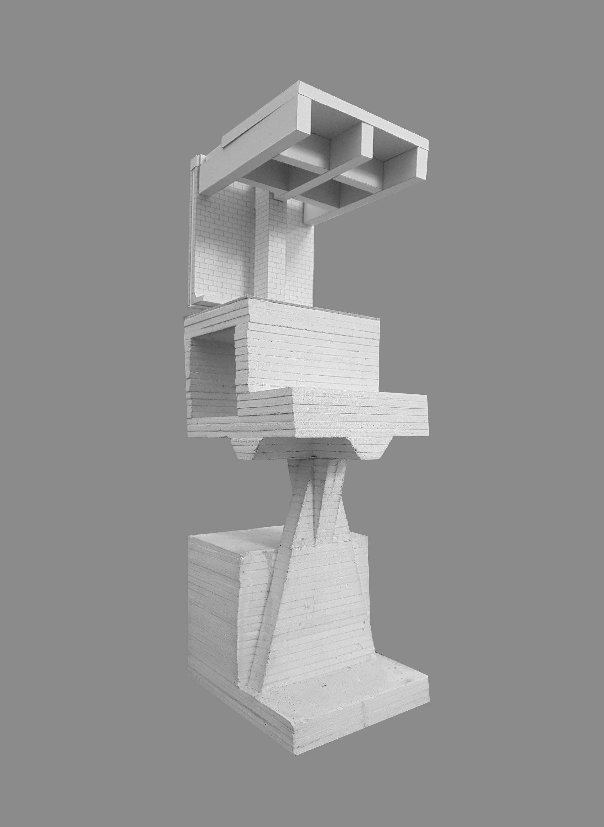
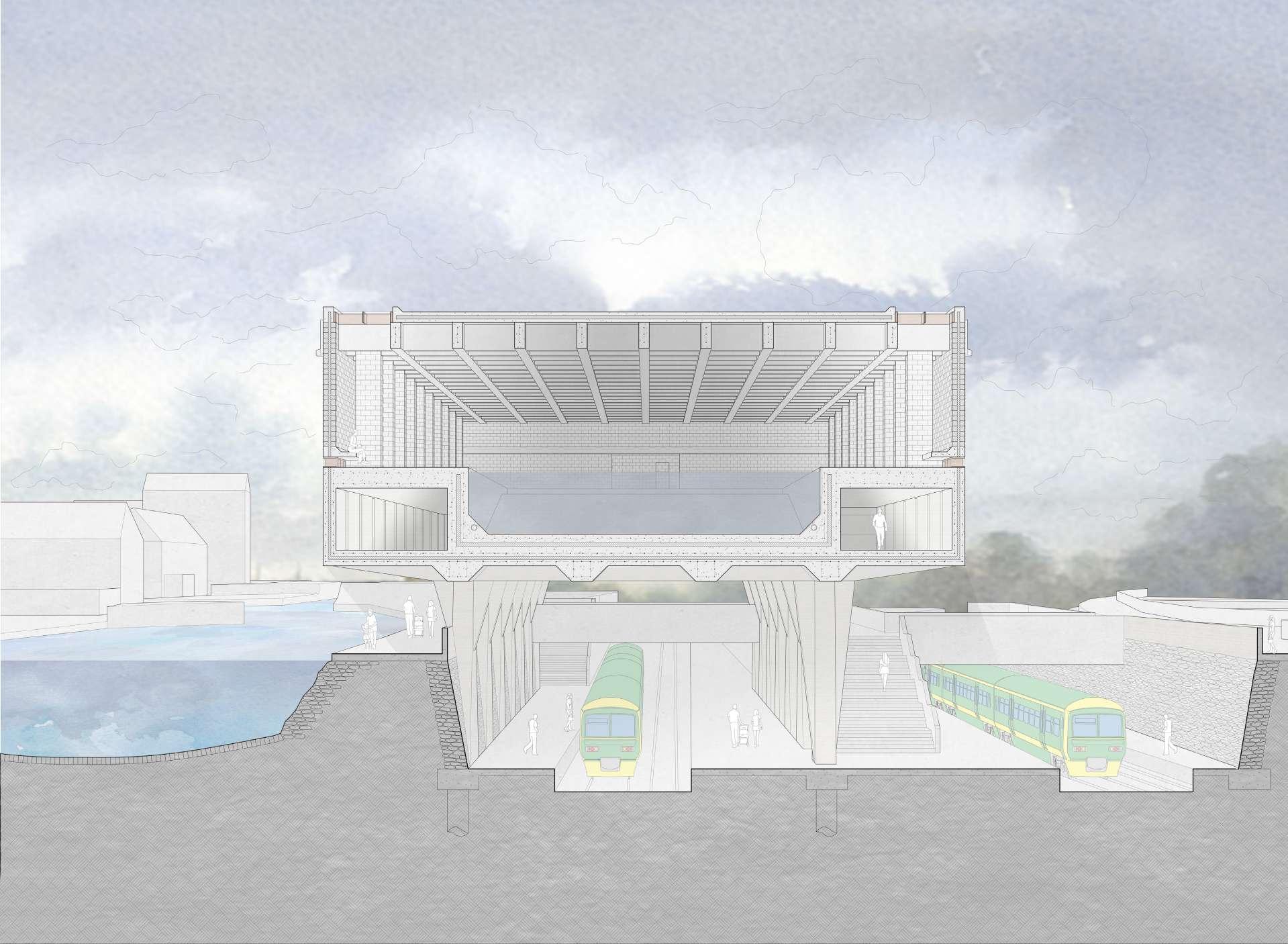
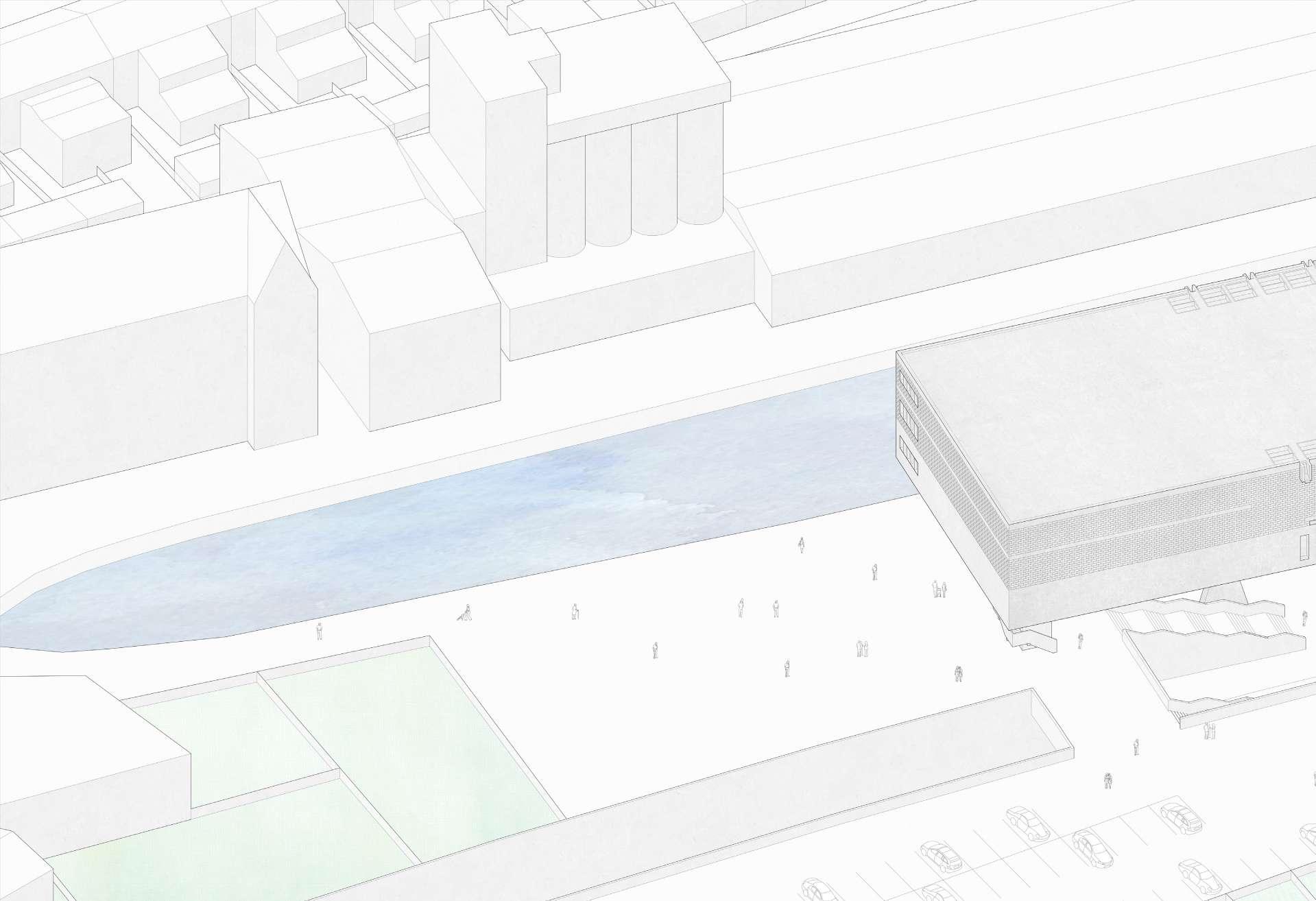 Fig. 5.3 Site Axo
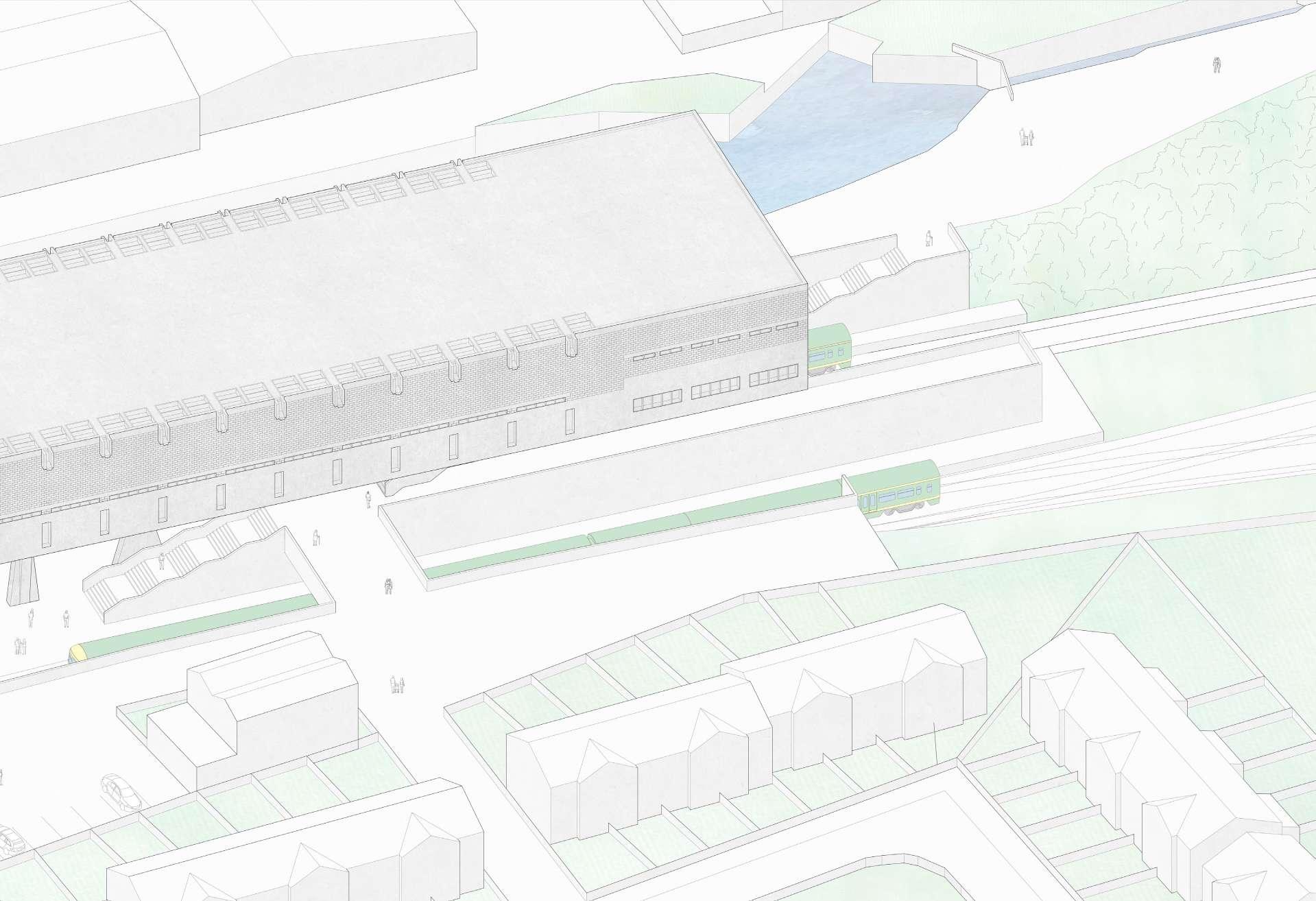
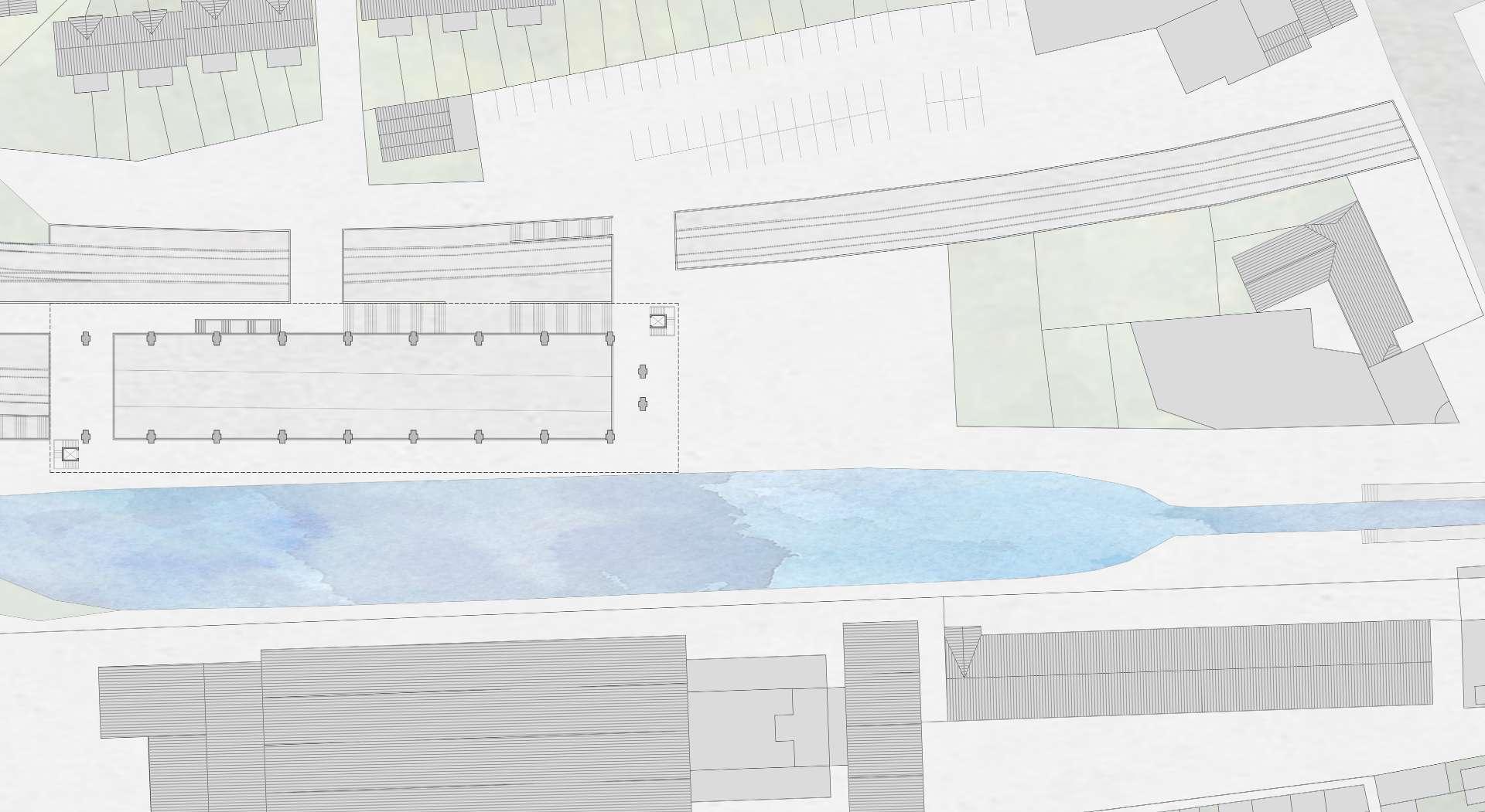
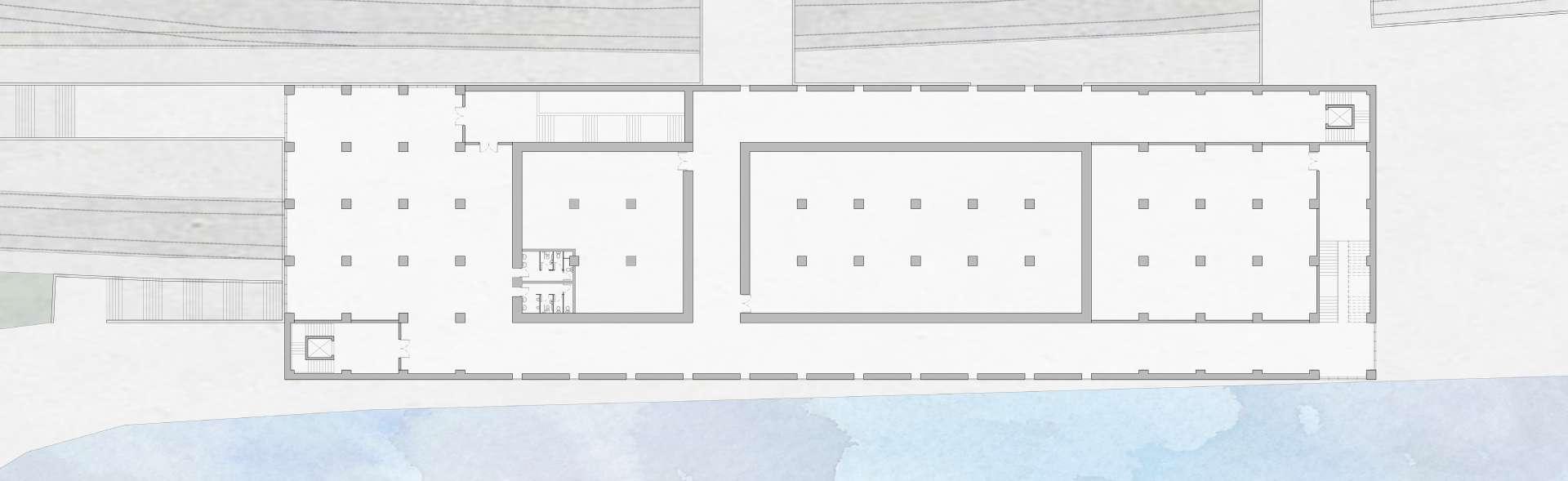
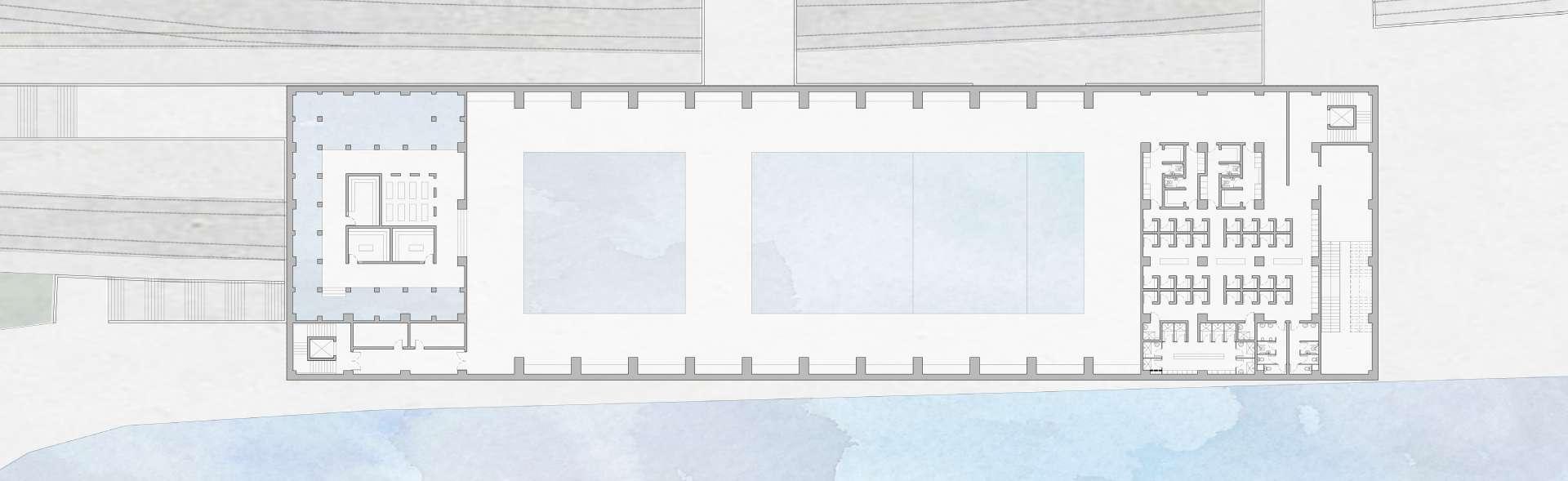 Fig.
Fig.
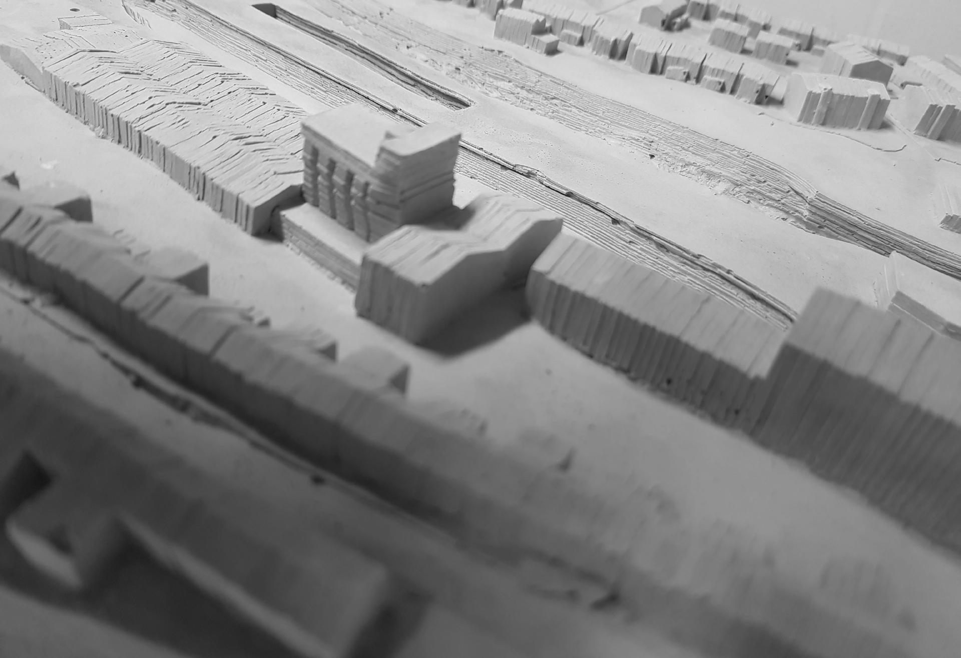
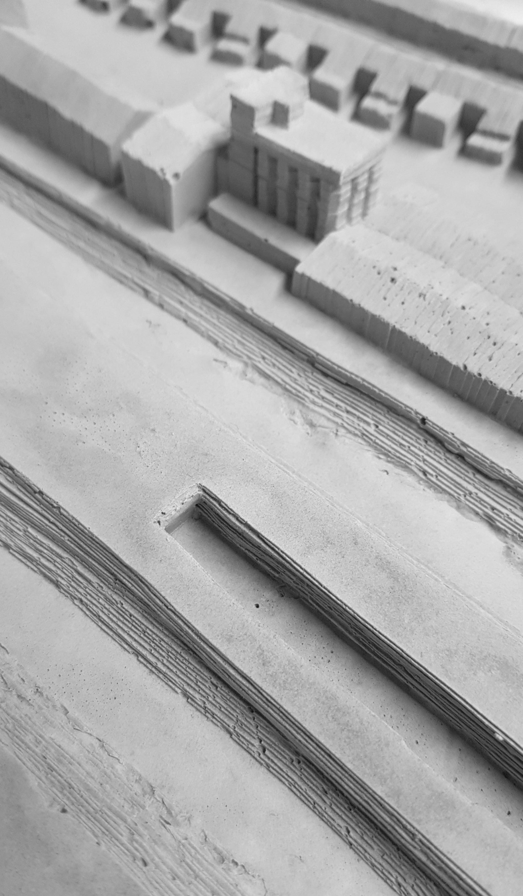
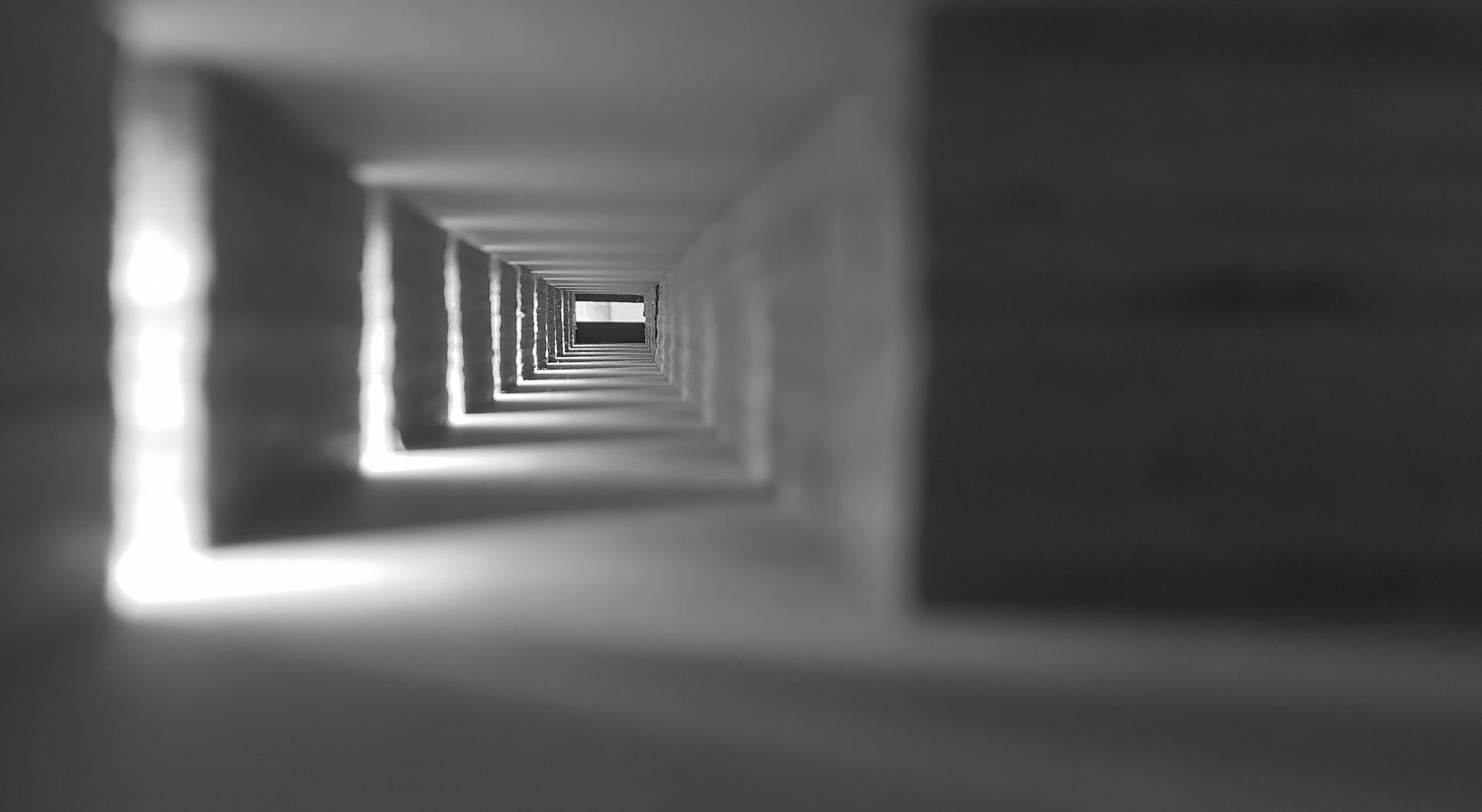 Fig. 5.8
Existing Site Model Model Photo
Fig. 5.9
Internal Circulation
Model Photo
Fig. 5.10
Existing Site Model
Model Photo
Fig. 5.8
Existing Site Model Model Photo
Fig. 5.9
Internal Circulation
Model Photo
Fig. 5.10
Existing Site Model
Model Photo
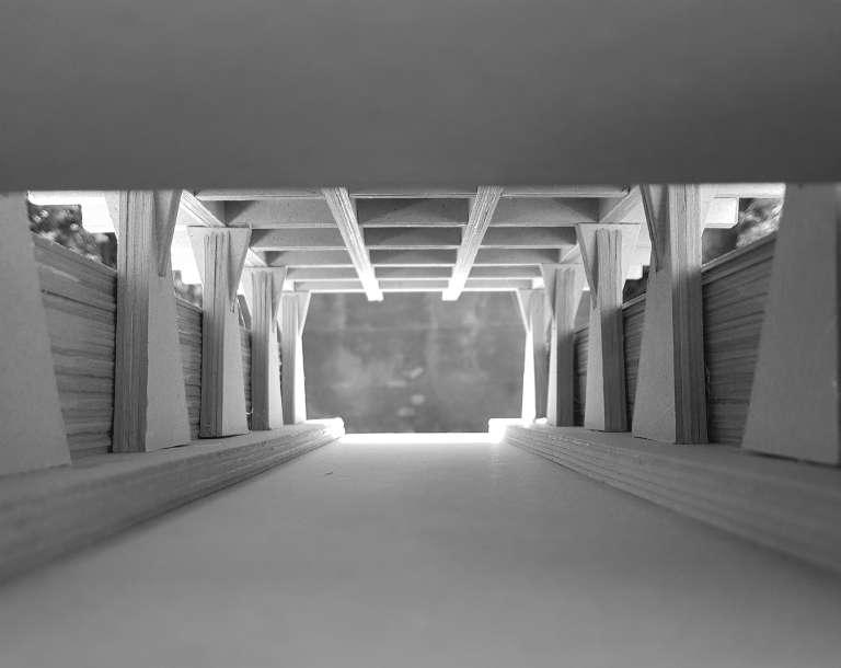
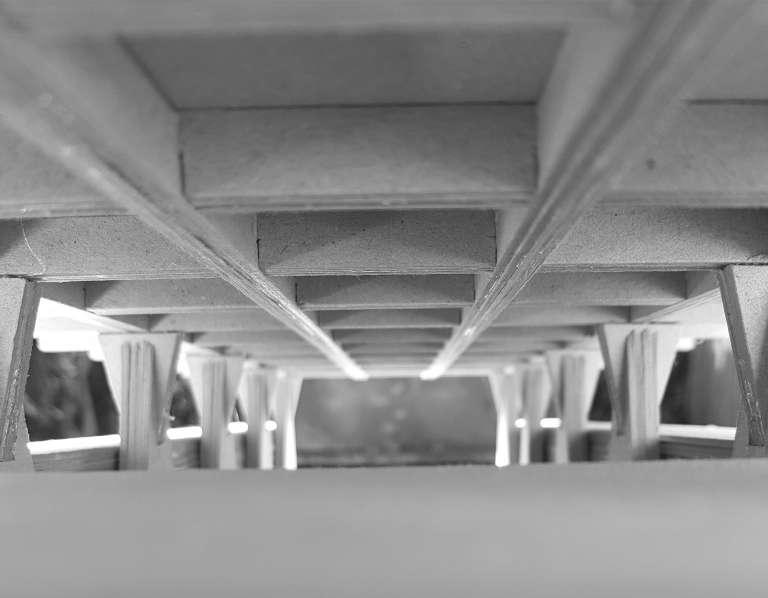
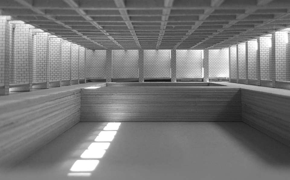
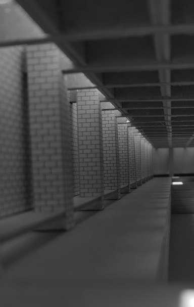
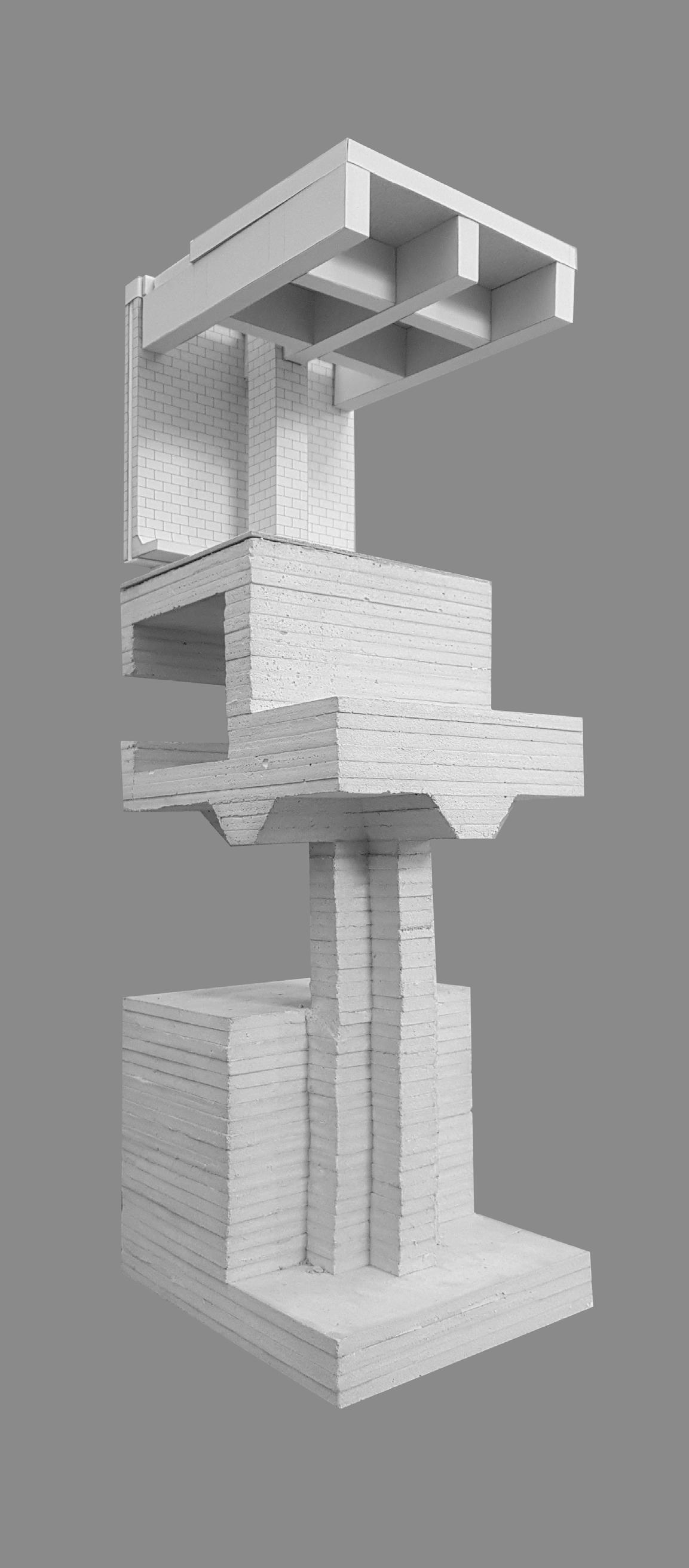
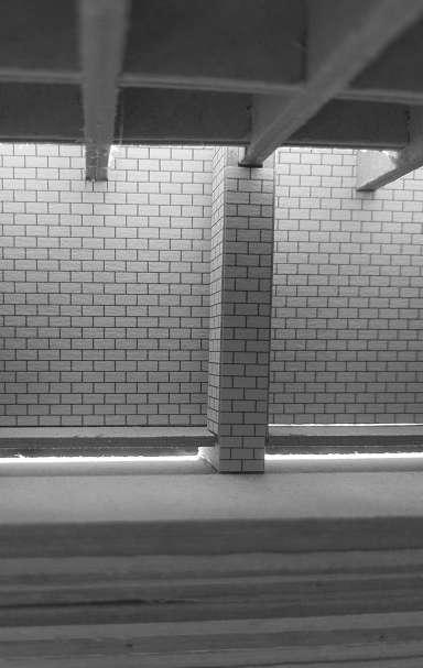 Fig. 5.11
Ground Level Model Photo
Fig. 5.13
Railway Platform Model Photo
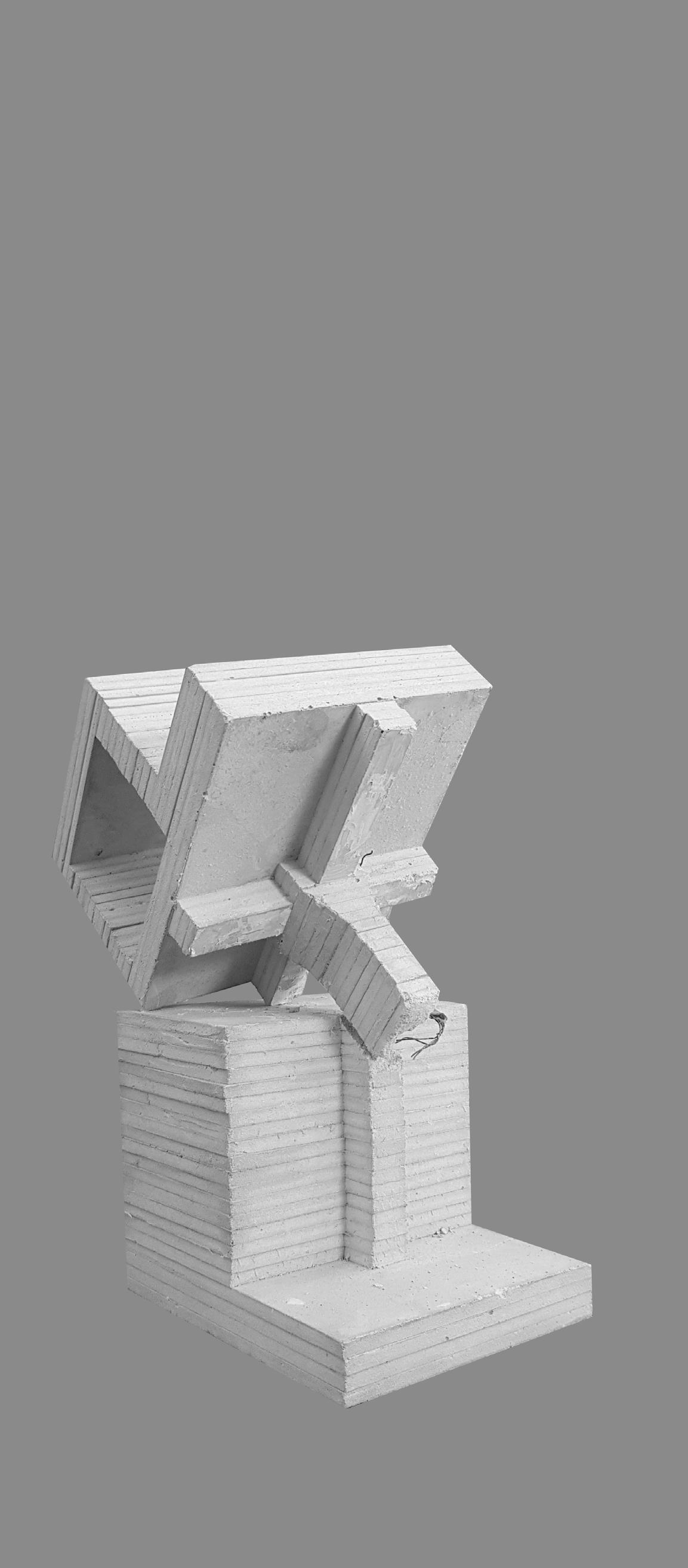
Fig. 5.14
Internal
Model Photo
Fig. 5.15
Internal
Model Photo
Fig. 5.12
Internal
Model Photo
Fig. 5.11
Ground Level Model Photo
Fig. 5.13
Railway Platform Model Photo
Fig. 5.14
Internal
Model Photo
Fig. 5.15
Internal
Model Photo
Fig. 5.12
Internal
Model Photo
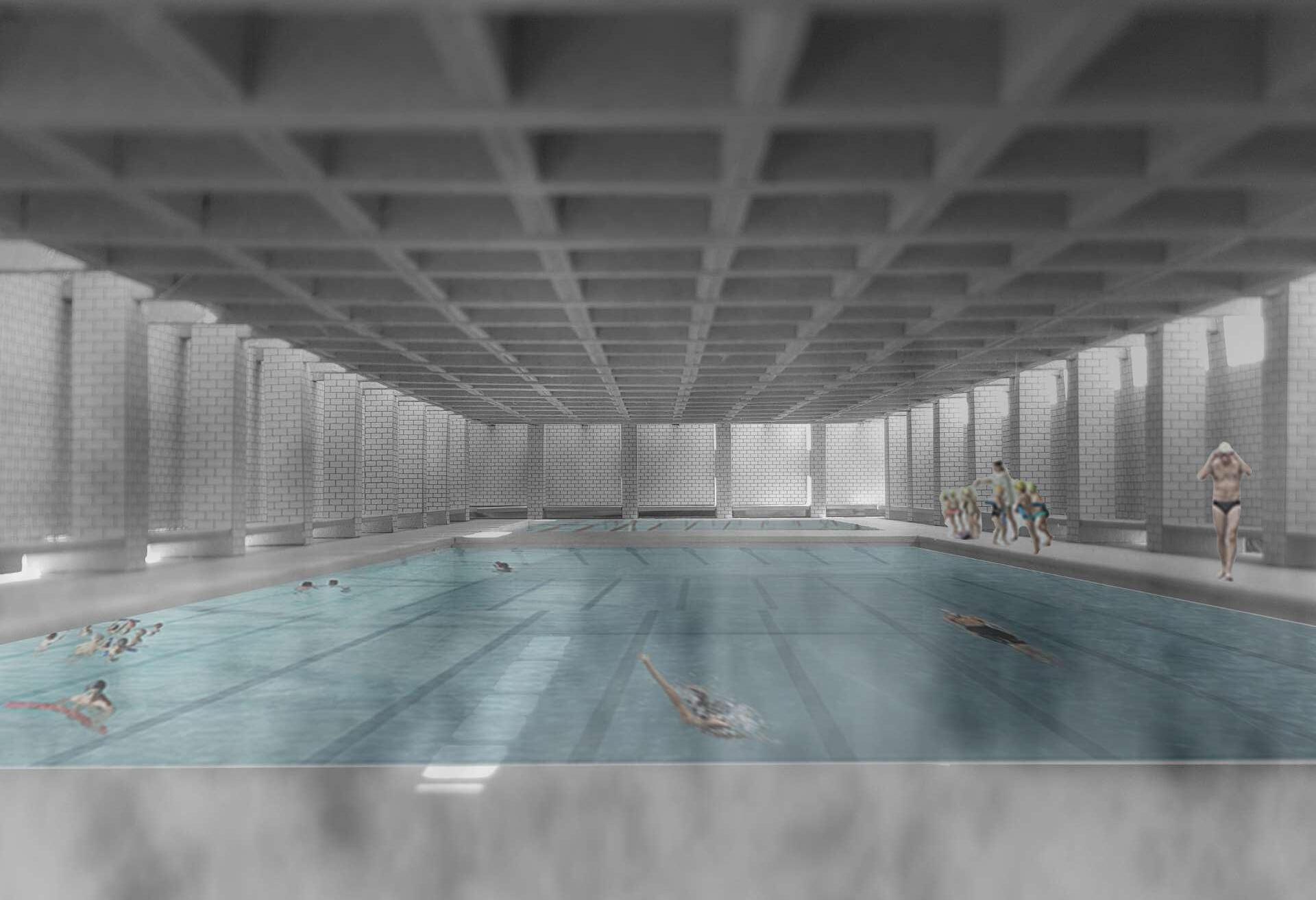 Fig. 5.16
Internal Swimming Pool Render
Fig. 5.16
Internal Swimming Pool Render
Semester 1
Project 1
Project 2
Project 3
Thesis Dovelopment Report
Brief
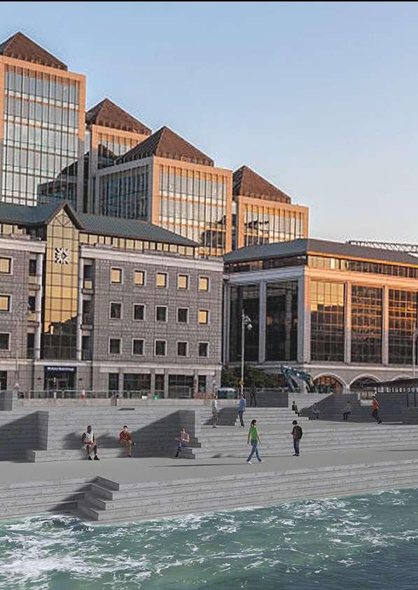
To design a small cafe across form the Custom House on the George@s Quay. The design must fulfil three requirements.
-Must provide for the predetermined programmatic requirement.
-Must serve as an experiment and develop the thesis idea
-Its form must arise in response to a primary function.
Site George's Quay Dublin 2
Through this project I will investigate how cast in situ concrete is utilised in the construction process and how the material properties enhance the form and function of the building.
The proposed design is located on the edge of the Quay wall and it expresses the cast in situ construction process. The proposed landscape acts as an artificial landscape that connects the street with the River Liffey. The caf is situated within the landscape and activates the area, with sheltered seating areas carved within the steps.
Understanding of the material properties and construction process is necessary. Cast is situ concrete is a very complex construction process. Better knowledge of the construction of the formwork necessary.
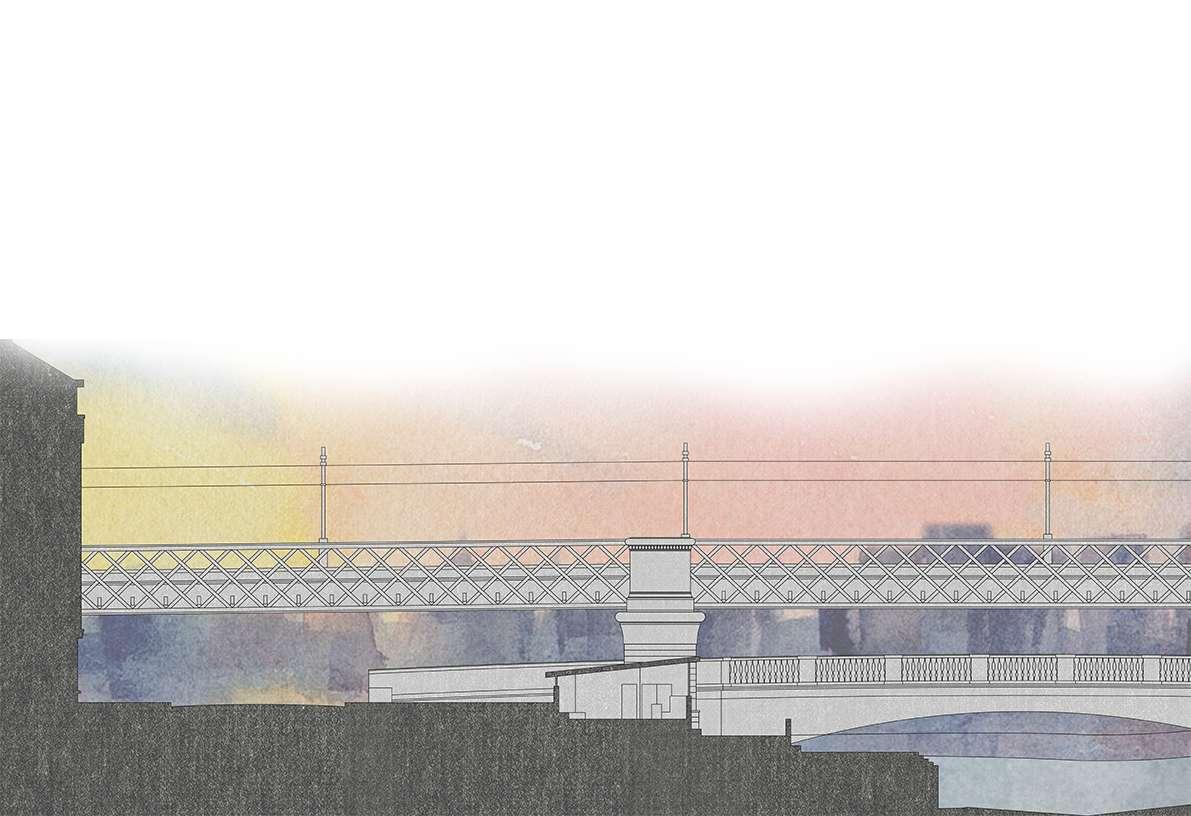 Fig. 7.5 Site Section
Fig. 7.2
View 1
Fig. 7.3
View 2
Fig. 7.4
View 3
Fig. 7.5 Site Section
Fig. 7.2
View 1
Fig. 7.3
View 2
Fig. 7.4
View 3
To study and adopt an idea from the construction of a precedent that would enable the thesis idea and to design an Interpretive centre for the Bull Island. It is located adjacent to the access road. The project must consist the following: lobby, staff office, toilets, meeting rooms, three exhibition rooms and a viewing platform.
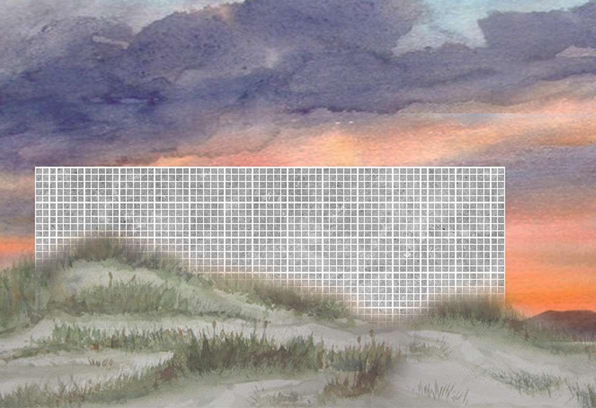
Through this project I will investigate how the modular concrete block is utilised in the construction process and how the material properties enhance the form and function of the building. The precedent for this project is the Storer House (Los Angeles) by Frank Lloyd Wright.
Precedent- Frank Lloyd Wright has designed four houses using the textile block, a textured concrete block that was created on site.
Design Proposal- To use the same methodology as Frank Lloyd Wright the project consists of modular concrete block casted on site against the existing sand, the resulting blocks have a stone like roughness that represent the construction process.
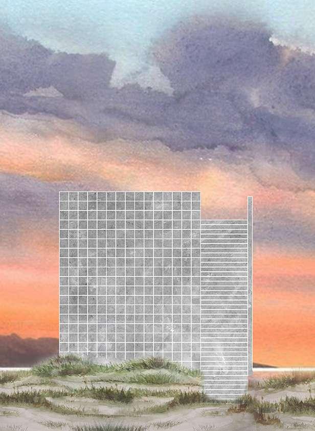
A better understanding of the methodology used by Frank Lloyd Wright was needed. The courtyards were insufficient to accommodate for natural lightning.
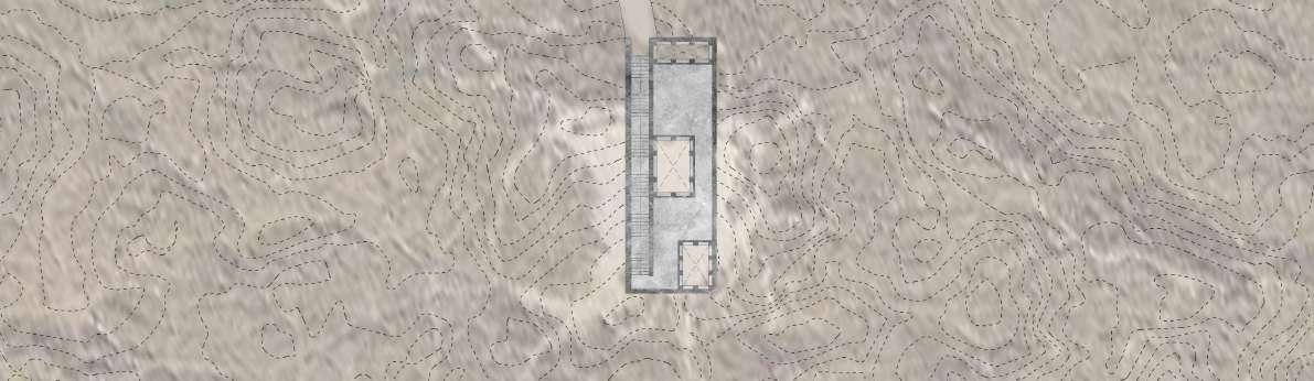 Fig. 7.8
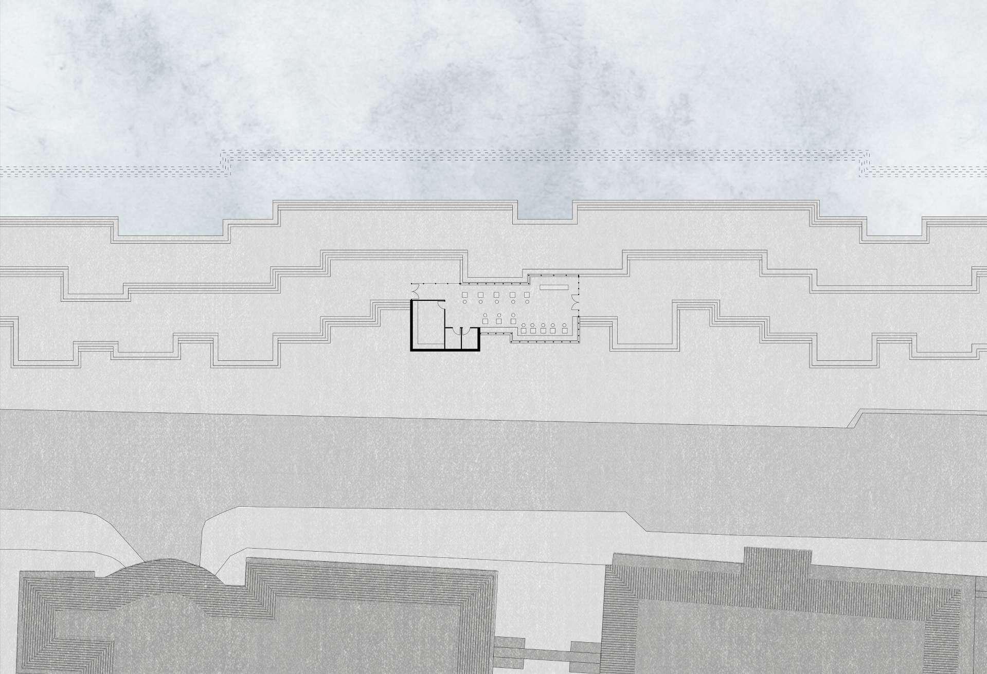
Site Plan
Fig. 7.10
Fig. 7.8
Site Plan
Fig. 7.10
Brief
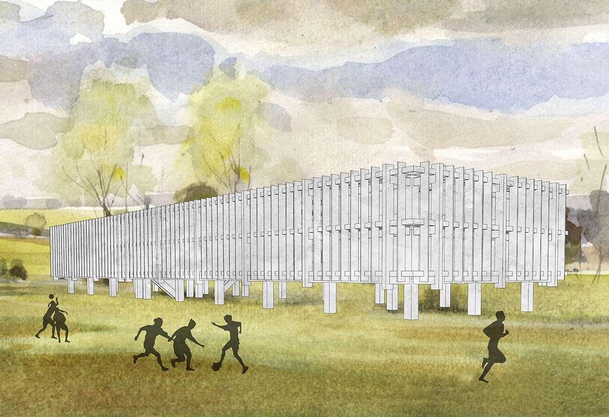
To create an indoor athletic centre in the park. It may be located within the park land or at the edge where it can engage with the adjacent communities and land scape. The specific site should be selected to enhance the thesis idea.
St Annes Park Raheny, Dublin 5
Through this project I will investigate how precast cast concrete is utilised in the construction process and how the material properties enhance the form and func tion of the building.
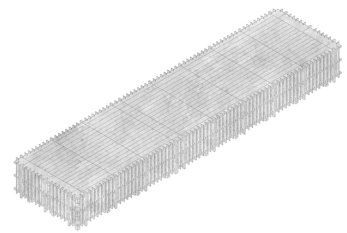
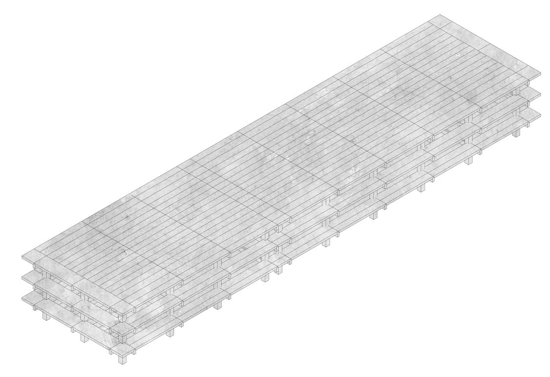
The proposed building is located on the existing football pitches accommodating for an indoor football pitch, two tennis courts and two squash courts along with shower rooms and bathrooms. The proposed structure allows for the building to become a viewing platform for the surrounding pitches
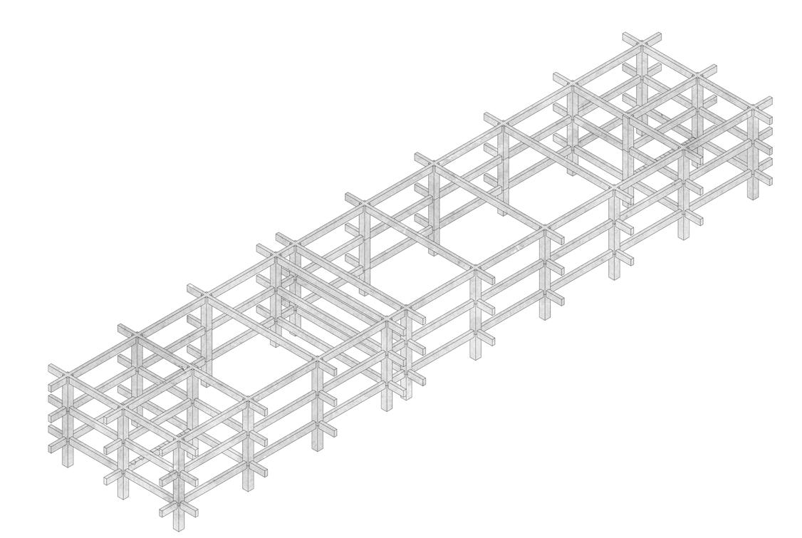
Using precast concrete as a material and construction process, the building con sists of three floors elevated above ground and is enveloped by a vertical concrete fa ade.
Better understanding of structural components within the design of a precast mem bers. The vertical structural elements were insufficient for the structural stability. The significance of the joint within the precast elements.