Begehbares Dachtragwerk aus Vierendeelträgern Walk-through Vierendeel girder roof structure
Längste Schrägseilbrücke der Welt mit drei Pylonen World‘s longest three-tower, inclined cable-stayed bridge
editorial
01/18 structure
Als Queen Elizabeth II. im Jahr 1964 die Forth Road Bridge in Schottland direkt neben der historischen Forth-Bridge eröffnete, wird
Redaktion / Editorial: Dr. Sandra Hofmeister (Chefredakteurin / Editor-inChief, V.i.S.d.P.) Andreas Gabriel
sie kaum damit gerechnet haben, mehr als 50 Jahre später noch eine weitere benachbarte Brücke über den Forth einzuweihen. Doch seit vergangenen Herbst überbrücken
In 1964, when Queen Elizabeth II opened the
nun drei beeindruckende Ingenieurbauwer-
Forth Road Bridge right next to the historic
ke aus drei Jahrhunderten den Forth und
Forth Bridge in Scotland, she would hardly
bilden ein weltweit einmaliges Ensemble von
have anticipated opening another adjacent
Großbrücken. Die neue Schrägseilbrücke
bridge over the Forth more than 50 years
Queensferry Crossing mit einer Gesamtlänge
later, as she did with the new inclined cable-
von über 2600 m und 210 m hohen Pylonen
stayed Queensferry Crossing last autumn.
erhält durch die in Feldmitte überkreuzten
Now three impressive engineering structures
Kabel die erforderliche Steifigkeit.
from three centuries cross the Forth and form
Neben dieser herausragenden Ingenieur
a unique ensemble of major bridges.
leistung präsentiert die aktuelle structure-
In addition to this outstanding work of engi-
Ausgabe weitere spannende Tragwerkslösungen, wie das offene Dachtragwerk eines Feinkostmarkts in Stuttgart, bei dem Holz und Stahl sich ergänzen, oder die ausdrucksstarke Stahlkonstruktion einer Fußgängerbrücke in Beer Sheva in Israel. Im Techno logie-Präsentationszentrum bei Chicago dienen die markanten Vierendeelträger des Dachs als Demonstrator der zur Fertigung eingesetzten Laserschnitttechnik. Mit dieser Ausgabe wird structure zur eigenständigen internationalen Fachzeitschrift für Bauingenieure. Die Zeitschrift structure bietet eine Plattform, die Ingenieure nicht nur als Ermöglicher sondern als Mitgestalter unserer gebauten Umwelt zeigt. Denn warum sollte – neben der fachlichen Exper tise – nicht auch die kreative Leistung der Ingenieure zum Selbstverständnis des Berufs
neering, this issue of structure presents further exciting structural engineering solutions, such as the exposed roof trusses of a delicatessen market in Stuttgart, where timber and steel
Roland Pawlitschko, Burkhard Franke, Amlis Botsch, (freie Mitarbeit / Contributing Editors) Grafik / Design: Sabine Drey Studio Umlaut (Cover) Redaktion Produkte / Product Information Editors: Katja Reich (Leitung / Manager), Rainer Bratfisch Übersetzung / Translation: Raymond Peat Verlag, Redaktion / Publisher, Editorial: DETAIL Business Information GmbH Messerschmittstraße 4 80992 München Anzeigen /Advertisement: anzeigen@detail.de tel.: +49 (0)89 381620-849 Vertrieb, Abonnement / Distribution, Subscription: detailabo@vertriebsunion.de tel.: 06123 9238-211 Einzelheft / Single issues: € 18,90
enhance each other, or the expressive steel structure of a footbridge in Be’er Sheba, Israel. In the technology presentation centre near Chicago, the striking Vierendeel roof girders demonstrate the laser cutting technology used in their fabrication. With this issue, structure becomes a standalone, international specialist magazine for structural engineers. The magazine offers a platform to show that engineers are not only facilitators but also co-designers of our built environment. Because – in addition to their technical expertise – why should not the creative capacity of engineers also form part of their professional identity?
gehören?
Andreas Gabriel redaktion@structure-magazin.de
01/18
editorial 1
inhalt content
hintergrund context
4 Konstruieren für die Welt von morgen Building for the world of tomorrow Werner Sobek
magazin journal
14 Gebogene Glas fassade für den höchsten Wolken kratzer Europas Curved Glass Facade for the Tallest Sky scraper in Europe Andreas Gabriel 16 DETAIL research DETAIL research 18 Bücher Books
2 inhalt
projekt und prozess
project and process 20 Technologiezentrum in Chicago Technology Center in Chicago Barkow Leibinger, Berlin Knippers Helbig, New York, Berlin 26 Nationalmuseum für afroamerikanische Geschichte und Kultur in Washington D. C. National Museum of African American History and Culture (NMAAHC) in Washington D. C. Freelon Adjaye Bond / SmithGroup, New York / Washington D. C. Guy Nordenson and Associates, New York Robert Silman Associates, Washington D. C.
32 Queensferry Crossing bei Edinburgh Queensferry Crossing near Edinburgh Jacobs Arup Joint Venture, Edinburgh Leonhardt, Andrä und Partner, Stuttgart Rambøll Group A/S, Kopenhagen Rambøll UK Limited, Southampton Sweco UK, Leeds 39 Fußgängerbrücke in Be‘er Sheva Pedestrian Bridge in Be’er Sheva Bar Orian Architects, Tel Aviv Rokach & Ashkenazi Consulting Engineers, Tel Aviv 44 Delikatessengroß markt in Stuttgart Delicatessen Wholesale Market in Stuttgart Robertneun Archi tekten, Berlin Assmann Beraten + Planen, Hamburg
produkte products
fachwissen
specialist know-how 50 Ultraleichtes, flexibles Schalungssystem für dünne, textilbe wehrte Betonschalen Ultralight, Flexible Formwork System for Thin, Textile- reinforced Concrete Shells Tom Van Mele, Tomás Méndez Echenagucia, David Pigram, Andrew Liew, Philippe Block
60 Baukonstruktion Building Construction 64 Sanierung Building Refurbish ment 67 BIM – Building Infor mation Modeling
54 Gefaltete Deckenplat ten aus Spannbeton Folded Plate Floor Slabs in Prestressed Concrete Andrea Pedrazzini
01/18
Konstruieren für die Welt von morgen Building for the world of tomorrow
Die Frage nach dem zukünftigen Berufsbild von Bauingenieuren ist in erster Linie die Frage nach dem Bauen für die Welt von morgen. Als Architekt und Ingenieur kann man sich mit Entwürfen und Konstruktionen auseinandersetzen, die lediglich auf der visuellen Ebene visionär sind. Doch beantwortet man damit die Frage nach der Zukunft unserer gebauten Umwelt? Projiziert man nicht vielmehr Alt hergebrachtes auf vermeintlich visionäre Zukunftsbilder, ohne die eigentlichen Grund fragen unserer Zeit zu stellen? Warum kommt es Planern und Gestaltern bei dem Versuch, die gebaute Welt von morgen zu erahnen, nur selten in den Sinn, an ein Elendsquartier zu denken? Weil wir diese Perspektive nicht aushalten würden? Aber was ist dann die Perspektive? Die Frage nach dem Bauen in der Zukunft ist die Frage nach der Zukunft selbst. Natürlich ist ein Vorausdenken immer mit dem Risiko des Irrens, des Scheiterns verbunden – aber ohne Risiko verharrt man immer auf gleichem Terrain. Wie es der Philosoph Hegel treffend zusammenfasste, ist die Angst vor dem Irrtum bereits der Irrtum selbst. Essenziell für das Skizzieren der gebauten Welt von morgen ist eine nüchterne Bestandsaufnahme globaler Trends von heute. Es geht darum herauszu finden, welche technischen und gesellschaftlichen Konstituenten dieser Zukunft sich heute bereits abzeichnen. Will man daraus Rückschlüsse auf die Aufgaben von Bauingenieuren ziehen, muss man zudem herausfinden,
Werner Sobek Der Autor Werner Sobek ist beratender Ingenieur und Architekt. Er leitet das 2000 gegründete Institut für Leichtbau Entwerfen und Konstruieren (ILEK) der Universität Stuttgart und lehrt darüber hinaus als Gastprofessor an zahlreichen Universitäten im In- und Ausland, u. a. in Graz, Singapur und Harvard. Seit 2017 ist er Sprecher des Sonderforschungsbereichs SFB 1244 über »Adaptive Hüllen und Strukturen für die gebaute Umwelt von morgen«. The author Werner Sobek is a consulting engineer and architect. He heads the Institute for Lightweight Structures and Conceptual Design (ILEK), which was founded in 2000, at the University of Stuttgart and lectures as a visiting professor at numerous universities in Germany and abroad, including Graz, Singapore and Harvard. He has been the chair of the special research field SFB 1244 working on “Adaptive building envelopes and structures for the built environment of tomorrow” since 2017.
The question of what the job of structural engineers will entail in the future is primarily one about building for the world of tomorrow. As architects and engineers, we can concern ourselves with designs and structures that are visionary only on the visual level. But what, some might ask, should our built environment be like in the future? Are we not more likely to project traditional thinking on to supposedly visionary images of the future without posing the really fundamental questions of our time? Why do planners and designers think only seldom in the context of a poverty-stricken region in their attempts to foster the built world of tomorrow? Because we would not be able to bear looking at it from this perspective? But what is this perspective? The question about building in the future is a question about the future itself. Of course, thinking ahead is always linked with the risk of error, a failure – but without risk we would never do anything new. The philosopher Hegel once appositely asked whether this fear of error is not the very error itself. An objective inventory of today’s global trends is essential for sketching the built world of tomorrow. This involves discovering the technical and social constituents of this future that are already apparent today. If we wish to draw conclusions about the tasks that structural engineers will be performing in the future, we must also find out who is conceiving this future or whether anyone at all is conceiving it. For only if this future is consciously shaped can we begin to look for our own role in it.
A
4 context
01/18
projects
projekte
Queensferry Crossing bei Edinburgh Queensferry Crossing near Edinburgh
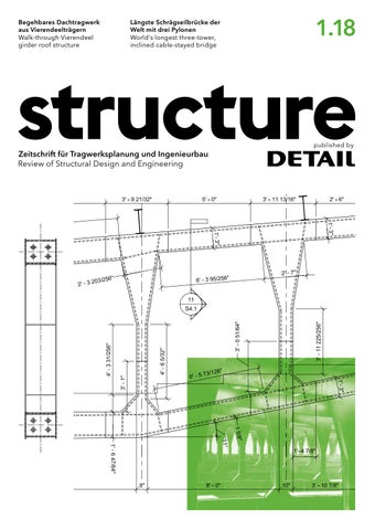
Die im September 2017 eröffnete Straßen brücke Queensferry Crossing spannt über den Firth of Forth und verbindet Edinburgh mit dem nördlichen Schottland. Sie ergänzt eine überlastete Hängebrücke aus dem Jahr 1964 die zukünftig nur noch dem Bus-, Fahrradund Fußgängerverkehr dienen wird. Zusam men mit der weltbekannten roten Ausleger brücke aus dem Jahre 1890, die den Bahnver kehr aufnimmt, entstand so ein einzigartiges Ensemble dreier verschiedener Brückenkonst ruktionen aus drei Jahrhunderten. Die Entscheidung für eine Schrägseilbrücke gründet sich neben ökonomischen Vorteilen
32 project and process
auf funktionelle Anforderungen und topogra fische Gegebenheiten: Ein aus dem Wasser ragender Felsen bot die Möglichkeit der Last abtragung in der Mitte des Firth. Da die Inge nieure – nicht zuletzt aus ästhetischen Erwä gungen – ein symmetrisches Gesamtsystem anstrebten, wurde im Hinblick auf die zu bei den Seiten erforderlichen Schifffahrtsöffnun gen eine Spannweite von 2≈ 650 m festgelegt. Daraus ergab sich die Lage der beiden äuße ren Pylone und der aufgeständerte Vorland bereich auf der Südseite. Mit einer Gesamt länge von 2,64 km ist die Schrägseilbrücke die BF längste der Welt mit drei Pylonen.
01/18
Opened in September 2017, the Queens bury Crossing road bridge spans the Firth of Forth and connects Edinburgh with northern Scotland. It replaces an overloaded suspen sion bridge constructed in 1964, which will in future carry only buses, cycles and pedes trians. Together with the world-famous red cantilever railway bridge from 1890, they form a unique ensemble of bridge structures from three centuries. The decision to adopt an inclined cablestayed bridge was based on economy, functional requirements and topographical circumstances: a rock projecting out of the
ater offered a potential support in the w middle of the firth. Because the engineers – not least out of aesthetic considerations – were seeking a symmetrical overall solution, they eventually settled on 2≈ 650 m main spans, which also provided the required ship ping navigation openings. This determined the position of the two outer towers and the approach viaduct on the southern side. With a total length of 2.64 km, the structure is the longest three-tower, inclined cable-stayed bridge in the world.
Entwurfsplanung / Planning and design: Jacobs Arup Joint Venture, GB–Edinburgh Tragwerksplanung / Structural engineering: Forth Crossing Design Joint Venture: Leonhardt, Andrä und Partner, Beratende Ingenieure VBI AG, D–Stuttgart Rambøll Group A/S, DK–Kopenhagen Rambøll UK Limited, GB–Southampton Sweco UK, GB–Leeds Ausführung / Construction: Forth Crossing Bridge Constructors: Hochtief Solutions AG, D–Essen American Bridge Internatio nal, USA–Coraopolis, Dragados S. A., GB–London Morrison Construction, GB–Edinburgh Prüfung / Independent check: URS, Aecom, GB–London Bauherr / Client: Transport Scotland, GB–Glasgow
W Video zum Bauablauf video of construction sequence structure-magazin.de/ 1-2018-edinburgh
01/18
projekt und prozess 33
3922
3922 5176
1624
4900
5653
2547
2547
5653
4900
1624
5176
39800
I
overlapped. The concrete slab at carriageway level is prestressed transversely to prevent cracking due to the centralised cable anchor ages and the reduction in torsional stiffness this would otherwise produce. The 202 m and 210 m high towers have an upwardly tapering reinforced concrete cross section with a maximum wall thickness of 2.40 m. The cables are anchored by steel hollow boxes with shear studs cast composite ly into the concrete in the upper part of the towers (Fig. G). A total of 288 inclined cables each consist of bundled seven-wire parallel strands. The least number of strands in any cable is 45. This is the shortest cable on the mid dle tower. In contrast, the shortest cables on the two o uter towers carry the largest loads and are therefore the “thickest” cables with 109 strands. The loads on the towers, cables and superstructure were much greater during construction than after the bridge was complete.
J
Seile der beiden äußeren Pylone auf deren Außenseite. Erst diese versetzte Anordnung ermöglicht die Überlappung der Seile. Die Betonplatte der Fahrbahn ist in Querrichtung vorgespannt, um eine Rissbildung infolge der mittigen Aufhängung und eine daraus resul tierende Minderung der Torsionssteifigkeit zu vermeiden. Die 210 m bzw. 202 m hohen Pylone haben einen sich nach oben verjüngenden Stahl
36 project and process
Construction While the middle tower was founded on rock protruding out of the water, up to 30 m diameter caissons were required for the outer towers and the first anchorage pier on the southern approach viaduct. The towers them selves were constructed using internal and ex ternal climbing forms in 54 lifts of up to 4 m in height. The inner climbing form was replaced by steel hollow boxes in the area of the cable anchorages. The maximum 16.20 m long steel elements for the superstructure were prefabricated in China and brought to Scotland by sea. The concrete for the top slab supporting the car riageway came from a mixing plant specially set up for the project in the nearby port of Rosyth. An over 80 m tall floating crane in stalled the first four segments of the super
01/18
know-how
fachwissen
Ultraleichtes, flexibles Schalungssystem für dünne, textilbewehrte Betonschalen Ultralight, Flexible Formwork System for Thin, Textile- reinforced Concrete Shells
HiLo ist eine Forschungs- und Innovationseinheit in den Bereichen Leichtbau und intelligente, adaptive Gebäudesysteme. Sie dient als zweigeschossiges Gemeinschaftsbüro, das 2018 am NEST (Next Evolution in Sustainable Building Technologies), dem modularen Forschungsgebäude der EMPA in Dübendorf in der Schweiz, gebaut wird. Das Dach der Einheit besteht aus einer zweilagigen, doppelt gekrümmten, kohlefaserverstärkten Betonschale mit integriertem hydronischen Heiz- und Kühlsystem sowie einer aufgesetzten DünnschichtPhotovoltaikanlage. Mit einer Gesamthöhe von 7 m und einer Oberfläche von 160 m2 überdeckt es eine Fläche von 120 m2. Gleichsam als Generalprobe für das innovative Bausystem wurde ein 1:1-Prototyp der unteren Schicht des Betondachs im Robotic Fabrication Lab des Instituts für Technologie in der Architektur der ETH Zürich realisiert. Der Unterbau des Systems besteht aus wiederverwendbaren Gerüstelementen, die eine Reihe von Holz-Randträgern tragen. Zwischen den Trägern und den Widerlagern bzw. Konsolen ist ein Seilnetz gespannt, während ein
Tom Van Mele Tomás Méndez Echenagucia David Pigram Andrew Liew Philippe Block Tom Van Mele ist Kodirektor und Forschungsleiter der Block Research Group (BRG) an der ETH Zürich. Tomás Méndez Echenagucia ist Architekt und Postdoktorand in der BRG. David Pigram ist Mitbegründer und Direktor des Architekturbüros supermanoeuvre und Dozent an der University of Technology in Sydney. Andrew Liew ist Bauingenieur und Postdoktorand in der BRG. Philippe Block ist ordentlicher Professor für Architektur und Tragwerk an der ETH Zürich, Gründer der BRG und Direktor des Nationalen Forschungsschwerpunkts (NFS) – Digitale Fabrikation. Tom Van Mele is co-director and head of research and development of the Block Research Group (BRG) at ETH Zürich. Tomás Méndez Echenagucia is an architect and post- doctoral researcher in the BRG. David Pigram is co-founder and director of the architecture firm supermanoeuvre and a senior lecturer at the University of Technology Sydney (UTS), Australia. Andrew Liew is a structural engineer and post-doctoral researcher in the BRG. Philippe Block is professor of architecture and structure at ETH Zürich, where he founded the BRG. He is also director of the Swiss National Centre for Competence in Research (NCCR) – Digital Fabrication.
A
50 specialist know-how
HiLo is a research and innovation unit for lightweight construction and smart and adaptive building systems. It is a two-storey innovation hub and collaborative working space that will be built in 2018 on NEST, EMPA’s modular research building in Dübendorf, Switzerland. The roof of the unit is a double-layered, doubly curved, carbon-fibre-reinforced concrete shell structure with integrated hydronic heating and cooling, and a thin-film photovoltaic system on top. With a total height of 7 metres, the roof covers an area of 120 square metres and has a total surface area of 160 square metres. A full-scale prototype of the bottom layer of the concrete roof was built in the Robotic Fabrication Lab of the Institute of Technology in Architecture at ETH Zürich as a dress rehearsal for its innovative construction system. The base of the system is composed of reusable scaffolding elements that support a set of timber edge beams. A cable net spans between the beams and the lower supports, and a fabric on top serves as shuttering for the sprayed concrete. The cable net is comprised of custom-cut steel cables connected by rings and brackets and is designed such that it deflects under the weight of the wet concrete into the correct final geometry, which it then supports until the shell has cured. To achieve this, the cable net must be precisely tensioned at the correct angle from specific anchor points in the CNC-milled edge beams. Cable net design The anticlastic shape of the concrete shell structure is the result of a custom-developed, multi-criteria optimisation process that balances architectural and functional constraints, such as possible touchdown regions, headroom clearances and solar orientation, with structural and fabrication requirements. Through a best-fit form-finding procedure, the specific non-uniform prestress of the cable net that would allow it to deform into this target shape under the 20 tonnes of wet concrete was then determined. The topology of the cable net was defined to best reflect the features of the anticlastic target shape, while minimising the required number of cable elements, controlling the sizes of the faces and dealing with the concentration of cables in the funnelling parts. Allowable forces were constrained during the form-finding process to
01/18
darüberliegendes Gewebe als Schalung für den Spritzbeton dient. Zusammengesetzt ist das Seilnetz aus genau zugeschnittenen Stahlseilen, die durch Ringe und Klammern verbunden sind – die richtige Endgeometrie erreicht es unter dem Gewicht des nassen Betons, den es trägt, bis die Schale ausgehärtet ist. Damit dies gelingt, muss das Netz von bestimmten Befestigungspunkten an den CNCgefrästen Randträgern im richtigen Winkel angebracht und präzise vorgespannt werden. Gestaltung des Seilnetzes Die gegensinnig gekrümmte Form der Betonschale resultiert aus einem eigens entwickelten Optimierungsprozess, der architektonische und funktionale Aspekte (z. B. Befestigungs bereiche, Durchgangshöhen oder die Ausrichtung zur Sonne) mit Konstruktions- und Fertigungsanforderungen in Einklang bringt. Mit einem inversen Formfindungsverfahren wurde anschließend die genaue, ungleich mäßige Vorspannung ermittelt, durch die das Seilnetz unter der Last des 20 t schweren Nassbetons seine finale Form erreicht. Die räumliche Struktur des Netzes war dabei so zu definieren, dass sie nicht nur optimal den Besonderheiten der gegensinnig gekrümmten Netzform entspricht, sondern zugleich die Anzahl der erforderlichen Seilelemente minimiert, die Maximalgröße der Netzfelder miteinbezieht und die höhere Seildichte in den trichterförmigen Bereichen berücksichtigt. Um einen sauberen Übergang zur verglasten Fassade zu schaffen, kamen außerdem besondere Seile entlang vertikaler Ebenen zum Einsatz. Im Verlauf des Formfindungsprozesses wurden die zulässigen Kräfte beschränkt, um die erforderlichen Größen der Seilnetzkompo nenten zu begrenzen. Die Gestaltung der Knoten sorgt dafür, dass alle Seile die nötigen Freiheitsgrade (axial, in der Schalenebene und senkrechte Rotation) haben, um der gewünschten Schalengeometrie entsprechen zu können. Zudem besitzen die Knoten Vorrichtungen zum Ausrichten und Befestigen der
B
limit the required sizes of the cable net components. The specific node design ensured that all cables have the necessary degrees of freedom to conform to the required shell geometry (axial, in-plane and perpendicular rotation). It incorporates features to align and attach the fabric shuttering, to fix the textile reinforcement at the correct height, to register the concrete thickness and to facilitate as-built measurement from below with two spherical markers on the nodes’ central axis. The developed construction system was designed to compensate for unavoidable deviations from the theoretical model, for example due to fabrication and assembly tolerances of the edge beam and the supporting scaffolding structure, by means of an adaptive control system. Tightening or loosening the cables at the perimeter alters the forces within the cable net, steering the shape of the shuttering from an imperfect starting point towards the desired shape. An algorithm was implemented to determine the precise adjustment to be applied at each boundary cable to best direct the cable net towards the intended form while respecting maximum cable stress constraints.
A
Struktureller Gesamtaufbau: Traggerüst, Schalungssystem und textilbewehrte Betonschale (von unten nach oben). B, C Seilnetzknoten A
s tructural system components: supporting scaffold, formwork system and textile- reinforced concrete shell (from bottom to top). B, C cable net nodes
C
01/18
fachwissen 51
Baukonstruktion Building Construction
swisskrono.de/elementbauweise
schneider-holz.com
Brettsperrholz für Dach, Wand und Decke Im November 2017 startete bei Best Wood Schneider die Produktion von Brettsperrholzelementen mit einer Flankenverleimung der Längs- und Querlagen. Die Einzellamellen werden zunächst zu massiven Einschichtplatten verleimt, die anschließend nochmals kalibriert werden. Der formaldehydfreie PU-Klebstoff trägt zu einer hervorragenden Ökobilanz der Massivholzelemente bei. Technisch werden die drei-, fünf- und siebenschichtigen Massivholzelemente mit Längen bis 15 m, Dicken von 60 bis 280 mm und 0,90 bis 1,20 m Breite allen konstruktiven und architektonischen Anforderungen gerecht und können als Dach-, Decken- und Wandelemente eingesetzt werden. Cross-laminated timber for roofs, walls and ceilings In November 2017, Best Wood Schneider started producing glued laminated timber elements with sideglueing of the longitudinal and transverse layers. The individual lamellas are first glued to solid single-layer boards, which are then recalibrated. The formaldehyde-free PU adhesive contributes to the excellent ecological balance of the solid wood elements. Technically, the three-, five- and seven-layer solid wood elements with lengths of up to 15 m, thicknesses from 60 to 280 mm and widths of 0.90 to 1.20 m meet all the structural and architectural requirements, and can be used as roof, ceiling and wall elements.
60 products
Urbanes Bauen mit Holz Die Element- und Modulbauweise mit dem Holzbausystem Swiss Krono Magnumboard OSB mit massiven groß formatigen Wand-, Decken- und Dachelementen ist für den Neubau und für Aufstockungen, Sanierungen sowie Auf- und Ausbauten geeignet. Durch die rasterlose Vorfertigung ist das System so flexibel, dass sich Neu- und Anbauten an vorhandene anpassen lassen. Kurze Montagezeiten vermeiden aufwendige Baustelleneinrichtungen, reduzieren Lärm und ermöglichen kürzere Fristen bis zur Nutzung. An den Innenseiten können die Elemente direkt mit Putzen, Fliesen, Tapeten oder Farben beschichtet werden. Eine Beplankung mit Gipskarton, Spachteln und Schleifen sind nicht nötig.
Urban construction with wood The element and modular construction method with the Swiss Krono Magnumboard OSB timber construction system with massive large-format wall, ceiling and roof elements is suitable for new buildings as well as for extensions, renovations and superstructures. Due to the gridless prefabrication, the system is so flexible that new buildings and extensions can be easily adapted to existing ones. Short assembly times avoid complex construction site facilities, reduce noise and enable shorter time periods until use. The inside of the elements can be coated directly with plaster, tiles, wall coverings or paint. Planking with gypsum plasterboard as well as filling and sanding are unnecessary.
Produkten rechnerisch zugeordnet. Je nach Kundenwunsch kann der Anteil zwischen 25 und 100 % betragen – bei absolut identischen Pro dukteigenschaften im Vergleich zum fossilen Pendant.
performance-materials.basf.com polyurethanes.basf.de
Sandwichelement im Biomass Balance Verfahren Der BASF-Kunde Falk Bouwsystemen B. V. in den Niederlanden produziert Sandwich-Paneele mit einem möglichst hohen Anteil an nachwachsenden Rohstoffen. Die Fibon.Paneele werden kontinuierlich im Biomass Balance Verfahren produziert. Bei der Herstellung werden nachwachsende Rohstoffe, z. B. Biogas oder Bio-Naphta, gemeinsam mit fossilen Rohstoffen eingesetzt. Der Bioanteil wird nach einer durch den TÜV Süd zertifizierten Methode bestimmten
Sandwich element in the biomass balance process BASF’s customer Falk Bouwsysteme B. V. in the Netherlands produces sandwich panels with the highestpossible percentage of renewable raw materials. The Fibon panels are continuously produced in the biomass balance process. In the production process, renewable raw materials such as biogas and bio-naphtha are used together with fossil raw materials. The organic content is mathematically allocated to specific products using a method certified by TÜV Süd. Depending on the customer’s requirements, the percentage can be between 25 % and 100 % – with absolutely identical product properties compared to the fossil equivalent.
01/18
Fassadenplatten erlaubt die einfache, schnelle und sichere Montage mit Zeiteinsparungen bis zu 50 %. Der Bohrbefestiger SDA5 sorgt dank seiner speziellen Befestigergeometrie für eine sichere, dauerhafte Schraubverbindung.
Vielfältige Befestigungen für vor gehängte hinterlüftete Fassaden SFS intec bietet vom Wandhalter über Profile und Verbinder bis zu Verankerungen und Zubehörkomponenten Lösungen für die Befestigung vorgehängter hinterlüfteter Fassaden. Edelstahl-Wandhalter in V4A für die Unterkonstruktion verfügen über eine geringere Wärmeleitfähigkeit und höhere Stabilität im Vergleich zu Aluminium. Der Blindbefestiger TUF-S zur rückseitigen Befestigung von HPL-
Various fixings for ventilated curtainwall facades SFS intec offers solutions for attaching ventilated facades, ranging from wall brackets, profiles and connectors, to anchors and accessory components. Stainless-steel wall brackets in V4A for the substructure have a lower thermal conductivity and higher stability compared to aluminium. The TUF-S blind fastener for the rear-mounting of the HPL facade panels allows simple, quick and safe installation with time savings of up to 50 %. Thanks to its special fastener geometry, the SDA5 drill fastener ensures a secure and durable screw connection.
Brand- und Schallschutz mit Holzbauelementen Das zweistöckige Gebäude aus Massivholz der Vorschule in Contern/Luxemburg wurde auf die teils im Erdreich liegende Tischtennishalle auf gesetzt. Um die Anforderungen des Brand- und Schallschutzes zu erfüllen, kamen Flächenelemente von Lignatur zum Einsatz, die sich aufgrund von Brandwiderständen bis REI 90 und hervorragender akustischer Eigenschaften für Bauten mit viel Publikumsverkehr eignen. Alle Elemente sind in Sichtqualität hergestellt und mit Schubstählen ergänzt, somit fungieren sie auch als aussteifende Scheiben zur Gebäudestabilisierung.
Fire and noise protection with wooden building elements The two-storey solid wood preschool building in Contern/Luxembourg was built on top of the table-tennis hall, which is partly buried in the ground. In order to meet the fire and noise protection requirements, multifunctional panel elements from Lignatur were used, which are suitable for buildings with a large amount of public traffic due to their fire resistance up to REI 90 and excellent acoustic properties. All the elements are manufactured in visible quality and supplemented with push bars, so they also act as stiffening panels for the stabilisation of buildings.
sfsintec.de
aeronautec.de
Leichtes Bauen mit lichttechnischen Geweben Beim Neubau des Museums für moderne und zeitgenössische Kunst in Bozen/Italien (Architekturbüro KSV Krüger Schuberth Vandreike) kamen Aerosystem i-14 Decken- und Raumelemente aus Aerosound opaque perforiert sowie lichttechnisches und akustisch wirksames Fluorpolymer gewebe von Aeronautec zum Einsatz. Lichttechnisches Gewebe auf der Basis von Fluorpolymeren wie PTFE, PVDF und ETFE wird durch Beschichtung und Perforierung im Innenraum auch akustisch wirksam. Der Einsatz erfolgt z. B. in Großraumbüros und Präsentations- und Verkaufsräumen sowie Museen. Lightweight construction with lighttransmitting fabrics The new building of the Museum of Modern and Contemporary Art in Bolzano/Italy (designed by architectural office KSV Krüger Schuberth Vandreike) used Aerosystem i-14 ceiling and spatial elements made of Aerosound opaque perforated as well as light-transmitting and acousticallyeffective fluoropolymer fabric from Aeronautec. Light-transmitting fabrics based on fluoropolymers such as P TFE, PVDF and ETFE are also acoustically effective on account of their interior coating and perforation. They are used, for example, in open-plan offices, presentation and sales rooms as well as in museums.
lignatur.ch
62 products
01/18
Begehbares Dachtragwerk aus Vierendeelträgern Walk-through Vierendeel girder roof structure
Längste Schrägseilbrücke der Welt mit drei Pylonen World‘s longest three-tower, inclined cable-stayed bridge
Impressum / Imprint
Zeitschrift für Tragwerksplanung und Ingenieurbau Review of Structural Design and Engineering www.structure-magazin.de ISSN 2568-2253 Verlag / Publisher: DETAIL Business Information GmbH Messerschmittstr. 4 80992 München / Munich Tel. +49 (0)89 38 16 20-0, Fax +49 (0)89 38 16 20-866 www.detail.de Postanschrift / Postal address: Postfach / PO box: 50 02 05 80010 München / Munich Geschäftsführung / Managing Director: Karin Lang Redaktion / Editorial: Tel. +49 (0)89 38 16 20-884, redaktion@structure-magazin.de Dr. Sandra Hofmeister (SaH) (Chefredakteurin / Editor-in-Chief, V. i. S. d. P.) Andreas Gabriel (GA) Amlis Botsch (AB), Burkhard Franke (BF), Roland Pawlitschko (RP) (freie Mitarbeit / Contributing Editor) Grafik / Design: Sabine Drey, Studio Umlaut (Cover) Johanna Christiansen, Florian Köhler, Michaela Linder, Maria Remter (Assistenz / Editorial Assistants) Herstellung, CAD, DTP / Production, CAD, DTP: Peter Gensmantel (Leitung / Manager), Michael Georgi, Cornelia Kohn, Andrea Linke, Roswitha Siegler, Simone Soesters Ralph Donhauser (freie Mitarbeit / freelance contributor) Übersetzungen / Translation: Raymond Peat, Marc Selway Redaktion Produktinformation / Product Information Editors: Katja Reich (V. i. S. d. P.) Rainer Bratfisch (freie Mitarbeit / Contributing Editor) produkteredaktion@structuremagazin.de Verkauf und Marketing / Sales and Marketing: Claudia Langert (Verlagsleitung / Publishing Director V. i. S. d. P.) Hon. Prof. Meike Weber, Senior Vice President / Business Development Medialeistungen und Beratung / Media Services and Consulting: Annett Köberlein (Leitung / Manager) Tel: +49 (0)89 38 16 20-849 Anzeigendisposition / Advertisement Scheduling: Petra Ruckdäschel, Tel. +49 (0)89 38 16 20-879 Vertrieb und Marketing / Distribution and Marketing: Kristina Weiss (Leitung / Manager) Irene Schweiger (Vertrieb / Distribution) Tel. +49 (0)89 38 16 20-837 Repro / Reprographics: ludwig:media, Schillerstr. 10 5700 Zell am See Druck / Printing: W. Kohlhammer Druckerei GmbH + Co. KG Augsburger Straße 722 70329 Stuttgart CAD-Zeichnungen / CAD drawings: Alle CAD-Zeichnungen, die im Dokumentationsteil der Zeitschrift veröffentlicht werden, wurden mit dem Programm erstellt.
01/18
All CAD drawings in the Documen tation section were produced with VectorWorks®. Abonnementverwaltung und Adressänderungen / Subscriptions and address changes: Vertriebsunion Meynen Große Hub 10, 65344 Eltville, Tel. +49 (0)61 23 92 38-211 Fax: +49 (0)61 23 92 38-212 detailabo@vertriebsunion.de structure erscheint 2018 am 1. März, 1. Juni, 3. September und 3. Dezember / structure appears in 2018 on 01 March, 01 June, 03 September and 03 December. structure ist einzeln oder im Abonnement über den DETAIL Online Shop oder den Buchhandel erhältlich / structure can be bought individually or on subscription via the DETAIL Online Shop or bookstores. www.detail.de/structure Bezugspreise / Prices: structure Einzelheft / Single issues: € 18,90 zzgl. Versandkosten / plus shipping costs Abonnement / Subscription: (4 Ausgaben inkl. Versandkosten / 4 issues including shipping): Inland / Germany: € 79,– / Ausland / Other countries: € 89,– Studenten / Students: Inland / Germany: € 45,– / Ausland / Other countries: € 55,– Ausland zzgl. MWSt, falls zutreffend / Other countries plus VAT, if applicable Abonnements sind 6 Wochen vor Ablauf kündbar / Subscription cancellation 6 weeks before expiry. Konto für Abonnementzahlungen / Bank details for subscription payments: Deutsche Bank München BLZ 700 700 10 · Konto 193 180 700 IBAN: DE24700700100193180700 SWIFT: DEUTDEMM Alle Rechte vorbehalten. Für unverlangte Manuskripte und Fotos wird nicht gehaftet. Nachdruck nur mit Genehmigung. Für Vollständigkeit und Richtigkeit aller Beiträge wird keine Gewähr übernommen. All rights reserved. No liability is accepted for unsolicited manuscripts or photos. Reproduction only with permission. No guarantee can be given for the completeness or correctness of the published contributions. Bei Nichtbelieferung ohne Ver schulden des Verlages oder infolge von Störungen des Arbeitsfriedens bestehen keine Ansprüche gegen den Verlag. No claims can be accepted for non- delivery resulting from industrial disputes or where not caused by an omission on the part of the publishers. Zurzeit gilt Anzeigenpreisliste Nr. 1. © 2018 für alle Beiträge, soweit nicht anders angegeben bei DETAIL Business Information GmbH. Current valid advertising rates are listed on Rate Card No. 1. © 2018 DETAIL Business Information GmbH, for all contributions, unless otherwise stated. Dieses Heft ist auf chlorfrei gebleichtem Papier gedruckt. This journal is printed on chlorinefree bleached paper. Die Beiträge in structure sind urheberrechtlich geschützt. Eine Verwertung dieser Beiträge oder von Teilen davon (z. B. Zeichnungen) sind auch
im Einzelfall nur in den Grenzen der gesetzlichen Bestimmungen des Urheberrechtsgesetzes in der jeweils geltenden Fassung zulässig. Sie ist grundsätzlich vergütungspflichtig. Zuwiderhandlungen unterliegen den Strafbestimmungen des Urheberrechts. Any use of contributions in whole or in part (including drawings) is permitted solely within the terms of relevant copyright law and is subject to fee payment. Any contravention of these conditions will be subject to penalty as defined by copyright law. Redaktionsbeirat / Editorial Board Prof. Christoph Ackermann Prof. Dr. Anette Bögle Dr. Oliver Englhardt Prof. Dr. Stephan Engelsmann Knut Göppert Dr. Bernhard Hauke Prof. Dr. Steffen Marx Prof. Dr. Lamia Messari-Becker Stefan Schmidt Dr. Heiko Trumpf Joram Tutsch
Abbildungsnachweis / Photo credits Fotos ohne Nennung sind Architekten- / Ingenieursaufnahmen, Werkfotos oder stammen aus dem Archiv DETAIL. Photos for which no credit is given were either provided by the respective architects or they are product photos from the DETAIL archives. Seite / pp. 1, 34 oben / top, 37 unten / bottom: bastian.kratzke@lap-consult.com Seite / p. 3: Evelina Zapala / ILEK Seite / pp. 4, 6 oben / top: Werner Sobek Seite / pp. 5, 10: Stefanie Weidner / ILEK Seite / pp. 6 unten / bottom, 7– 9: ILEK Seite / p. 13: Lakhta Seite / pp. 14 unten links / bottom left, 14 unten Mitte / bottom centre, 46 oben / top: Andreas Gabriel Seite / p. 14 unten rechts / bottom right: Christian Schittich Seite / pp. 16, 17 links / left: TU Darmstadt, KGBauko Seite / p. 17 rechts / right: TU Darmstadt, Fachgebiet Stahlbau Seite / p. 18 oben / top: Iwan Baan Seite / p. 18 unten / bottom: Block Research Group / ETH Zürich Seite / pp. 19, 32, 33: Transport Scotland Seite / pp. 20, 22, 24 oben / top: Steve Hall Seite / pp. 21, 23, 25: Simon Menges Seite / p. 24 unten / bottom: McShane Construction Seite / pp. 26, 27 unten / bottom: Brad Feinknopf Seite / pp. 27 oben / top, 30, 31: Alan Karchmer Seite / pp. 28, 29: Richard Barnes Seite / pp. 34 unten / bottom, 36, 37 oben / top: lukas.kohler@lap-consult.com
Seite / pp. 35, 38: PA Images Seite / pp. 39– 41, 43 oben / top: Amit Geron Seite / pp. 42, 43 unten / bottom: Nir Ovadya Seite / pp. 45, 46 Mitte / centre, 46 unten / bottom, 47: Annette Kisling Seite / pp. 49, 51 unten / bottom, 52 oben / top, 52 unten Mitte / bottom centre, 52 unten rechts / bottom right: Naida Iljazovic, ITA der ETH Zürich Seite / pp. 50, 52 unten links / bottom left, 53 oben / top: ITA der ETH Zürich Seite / pp. 51 oben / top, 53 unten / bottom: Michael Lyrenmann / ITA der ETH Zürich Seite / pp. 54, 55, 58: Roger Frei Seite / p. 56: ingegneri pedrazzini guidotti Seite / pp. 57, 59: Corinna Menn & Mark Ammann Seite / p. 60 oben rechts / top right: Balazs Komforthaus Seite / p. 62 oben rechts / top right: Ludwig Thalheimer Seite / p. 62 unten / bottom: Jean Theisen Seite / p. 64 links / left: Rüdiger Mosler Seite / pp. 65 oben / top, 65 links / left: R. Borgmann Seite / p. 66 oben / top: Holger Vonderlind Cover structure 1/18 Technologiezentrum in Chicago / Technology Center in Chicago Architekten /Architects: Barkow Leibinger Ganzseitige Schwarzweißfotos / Black-and-white photos introducing main sections: Seite / p. 3: Textile Oberflächenstruktur Textile surface structure Forschungsarbeit / Research project: ILEK Seite / p. 13: Lakhta Tower Architekten /Architects: Gorproject Seite / p. 19: Queensferry Crossing Entwurfsplanung / Planning and design: Jacobs Arup Joint Venture Seite / p. 49: Betonschalungssystem Formwork system for concrete shells Prototyp / Prototype: Block Research Group Seite / p. 59: Faltwerkdecke / Folded plate floor slab Tragwerksplaner / Structural engineer: ingegneri pedrazzini guidotti
impressum 73