Digital design and fabrication methods
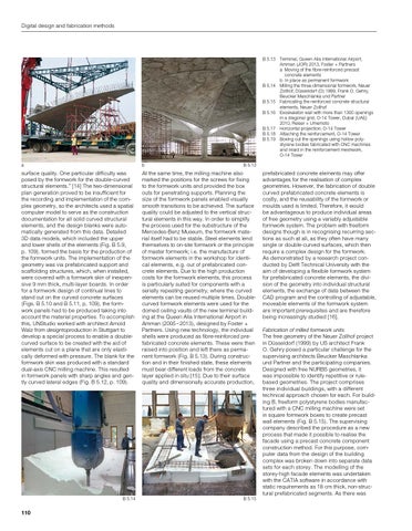
B 5.13 Terminal, Queen Alia International Airport, Amman (JOR) 2013, Foster + Partners a Moving of the fibre-reinforced precast concrete elements b In place as permanent formwork B 5.14 Milling the three-dimensional formwork, Neuer Zollhof, Düsseldorf (D) 1999, Frank O. Gehry, Beucker Maschlanka und Partner B 5.15 Fabricating the reinforced concrete structural elements, Neuer Zollhof B 5.16 Exoskeleton wall with more than 1300 openings in a diagonal grid, O-14 Tower, Dubai (UAE) 2010, Reiser + Umemoto B 5.17 Horizontal projection, O-14 Tower B 5.18 Attaching the reinforcement, O-14 Tower B 5.19 Boxing out the openings using hollow poly styrene bodies fabricated with CNC machines and inlaid in the reinforcement meshwork, O-14 Tower a
b
s urface quality. One particular difficulty was posed by the formwork for the double-curved structural elements.” [14] The two-dimensional plan generation proved to be insufficient for the recording and implementation of the complex geometry, so the architects used a spatial computer model to serve as the construction documentation for all solid curved structural elements, and the design blanks were automatically generated from this data. Detailed 3D data models, which included the upper and lower shells of the elements (Fig. B 5.9, p. 109), formed the basis for the production of the formwork units. The implementation of the geometry was via prefabricated support and scaffolding structures, which, when installed, were covered with a formwork skin of inexpensive 9 mm thick, multi-layer boards. In order for a formwork design of continual lines to stand out on the curved concrete surfaces (Figs. B 5.10 and B 5.11, p. 109), the formwork panels had to be produced taking into account the material properties. To accomplish this, UNStudio worked with architect Arnold Walz from designtoproduction in Stuttgart to develop a special process to enable a doublecurved surface to be created with the aid of elements cut on a plane that are only elastically deformed with pressure. The blank for the formwork skin was produced with a standard dual-axis CNC milling machine. This resulted in formwork panels with sharp angles and gently curved lateral edges (Fig. B 5.12, p. 109).
At the same time, the milling machine also marked the positions for the screws for fixing to the formwork units and provided the box outs for penetrating supports. Planning the size of the formwork panels enabled visually smooth transitions to be achieved. The surface quality could be adjusted to the vertical structural elements in this way. In order to simplify the process used for the substructure of the Mercedes-Benz Museum, the formwork material itself had to be stable. Steel elements lend themselves to on-site formwork or the principle of master formwork; i.e. the manufacture of formwork elements in the workshop for identical elements, e.g. out of prefabricated concrete elements. Due to the high production costs for the formwork elements, this process is particularly suited for components with a serially repeating geometry, where the curved elements can be reused multiple times. Doublecurved formwork elements were used for the domed ceiling vaults of the new terminal building at the Queen Alia International Airport in Amman (2005 – 2013), designed by Foster + Partners. Using new technology, the individual shells were produced as fibre-reinforced prefabricated concrete elements. These were then raised into position and left there as permanent formwork (Fig. B 5.13). During construction and in their finished state, these elements must bear different loads from the concrete layer applied in situ [15]. Due to their surface quality and dimensionally accurate production,
B 5.14
B 5.15
110
B 5.13
prefabricated concrete elements may offer advantages for the realisation of complex geometries. However, the fabrication of double curved prefabricated concrete elements is costly, and the reusability of the formwork or moulds used is limited. Therefore, it would be advantageous to produce individual areas of free geometry using a variably adjustable formwork system. The problem with freeform designs though is in recognising recurring sections as such at all, as they often have many single or double-curved surfaces, which then require a complex design for the formwork. As demonstrated by a research project conducted by Delft Technical University with the aim of developing a flexible formwork system for prefabricated concrete elements, the division of the geometry into individual structural elements, the exchange of data between the CAD program and the controlling of adjustable, moveable elements of the formwork system are important prerequisites and are therefore being increasingly studied [16]. Fabrication of milled formwork units The free geometry of the Neuer Zollhof project in Düsseldorf (1999) by US architect Frank O. Gehry posed a particular challenge for the supervising architects Beucker Maschlanka und Partner and the participating companies. Designed with free NURBS geometries, it was impossible to identify repetitive or rulebased geometries. The project comprises three individual buildings, with a different technical approach chosen for each. For building B, freeform polystyrene bodies manufactured with a CNC milling machine were set in square formwork boxes to create precast wall elements (Fig. B 5.15). The supervising company described the procedure as a new process that made it possible to realise the facade using a precast concrete component construction method. For this purpose, computer data from the design of the building complex was broken down into separate data sets for each storey. The modelling of the storey-high facade elements was undertaken with the CATIA software in accordance with static requirements as 18 cm thick, non-structural prefabricated segments. As there was