Stefan PrinciplesWinter–Structures –ManualExamplesofMulti-StoreyTimberConstruction
Edition ∂
Hermann Kaufmann
Stefan Krötsch

Translation of the first edition 2018: Christina McKenna, Douglas Fox, Meriel Clemett for keiki communication, Berlin (DE) Copy editing (English edition): Stefan Widdess, Berlin (DE)
Proofreading (English edition): Meriel Clemett, Bromborough (GB) Cover design based on a concept by: Wiegand von Hartmann, Munich (DE) Production and DTP: Simone ludwig:media,Reproduction:SoestersZell am See (AT) Printing and binding: Grafisches Centrum Cuno, Calbe (DE)
Editorial services
Steffi Lenzen (project manager) Jana Rackwitz (editorial services and layout), Cosima Frohnmaier, Sophie Karst, Sonja Ratz, Daniel Reisch, Eva Schönbrunner Charlotte Petereit (editorial assistant) Carola Jacob-Ritz (proofreading German edition)
MarionRalphDrawings:DonhauserGriese,Martin Hämmel, Simon Kramer, Dilara Orujzade, Janele Suntinger
© 2022 second edition English translation of the third, revised and expanded German edition 2021 “Atlas Mehrgeschossiger Holzbau” (ISBN: 978-3-95553-556-8) 2018 first edition English translation of the first German edition 2017 environmentPaper: Grocer Kraft (cover), Magno Volume (content)
AuthorsImprint
Research assistants: Ruth SandraStudentClaudiaKlingelhöfer-KrötschKöhler,DavidWolfertstetterassistants:Gressung,TobiasMüller,Maren Richter, Moritz Rieke, Sascha Ritschel, Konstanze Spatzenegger, Fabia Stieglmeier
Hermann Kaufmann Stefan Krötsch Stefan Winter Co-authors Sonja Geier, Annette Hafner, Wolfgang Huß, Holger König, Maren Kohaus, Frank Lattke, Klaus Mindrup, Lutz Müller, Anne Niemann, Daniel Rüdisser, Christian Schühle, Sandra Schuster, Manfred Stieglmeier, Martin Teibinger, Gerd Wegener
Translation into English: Mark Kammerbauer, Landshut (DE)
2
Bibliographic information published by the German National Library. The German National Library lists this publication in the German National Bibliography (Deutsche Nationalbibliografie); detailed bibliographic data is available on the Internet Thishttp://dnb.d-nb.de.atworkissubject to copyright. All rights reserved. These rights specifically include the rights of translation, reprinting, and presentation, the reuse of illustrations and tables, broadcasting, reproduction on microfilm or on any other media and storage in data processing systems. Furthermore, these rights pertain to any and all parts of the material. Any reproduction of this work, whether in whole or in part, even in individual cases, is only permitted within the scope specified by the applicable copyright law. Any reproduction is subject to charges. Any infringement will be subject to the penalty clauses of copyright law. This textbook uses terms applicable at the time of writing and is based on the current state of the art, to the best of the authors’ and editors’ knowledge and belief. All drawings in this book were made specifically by the publisher. No legal claims can be derived from the contents of this book.
DetailPublisher:Business Information GmbH, Munich ISBN:detail.de978-3-95553-581-0 (printed edition) ISBN: 978-3-95553-582-7 (e-book)
3 Contents Foreword 5 Part A Introduction 1 The Evolution of Multi-storey Timber Construction 8 2 Wood as a Resource 14 3 Solid Wood and Wood-based Products 18 4 Life Cycle Analysis 24 5 Indoor Air Quality – The Influence of Timber Construction 32 Part B Structural Systems 1 Structures and Load-bearing Systems 42 2 Construction Components and Elements 56 Part C Construction 1 Protective Functions 78 2 Thermal Insulation in Summer – A Question of Planning 94 3 The Layer Structure of Building Envelopes 98 4 The Layer Structure of Interior Construction Components126 5 Building Services Technology – Particularities of Timber Construction 136 Part D Process 1 Planning146 2 Digitalisation in Timber Construction154 3 Timber Production158 4 Prefabrication162 5 Solutions for Modernising and Expanding Existing Buildings172 Part E Examples of Buildings in Detail Joinery in Detail184 Project Examples190 Appendix SupportersIndex311ProjectImageDINGlossary302Bibliography300Authors298Standards306Credits308Participants310/Sponsors312
5 and economically viable buildings. This approach has long been typical to building in an urban context. Consider how construction methods were blended in the Middle Ages, when combinations of timber and stone made it possible to build impressive half-timbered structures, or Wilhelmian buildings, which seemingly consist of solid masonry on their exterior, while their horizontal construction elements such as slabs and roofs actually contain a large proportion of timber. The opportunities offered by modern means of construction motivate us to question the conventional and very narrow categorisation of timber structures into frame, panel and solid timber-based construction types and, as a result, expand upon them. Based on the possibilities of combining horizontal and vertical elements already in practice today, timber construction constitutes a fascinating and creative process. In conjunction with modern building envelope construction types, the range of applications for this renewable raw material is nearly boundless and ever-expanding. The continuous use of wood as a construction material and the resulting long-term carbon storage capacity and creation of carbon sinks are positive contributions to the struggle against global warming. Nevertheless, climate change will impact and transform the supply of timber. In future, wood as a natural building material will be available to us in a different supply mix than today. The availability of hardwood will likely grow, while softwood stock will simultaneously decline. This will necessarily result in new and further developments in wood-based materials and a much larger share of hardwood-based materials in multi-storey timber buildings than is the case thus far, with positive consequences. Many hardwood species feature much better strength and stiffness characteristics, allowing the production of very thin and lightweight construction components that open up entirely new design opportunities in the realm of multi-storey timber construction. The forestry industry in Europe has been a sustainable practice for centuries and demonstrates that thriving forests can be maintained while sustaining other functions, ranging from air purification and water storage to serving as a recreational space –despite the intensive harvesting of this raw material. Europe currently grows more wood than it uses. Germany, Austria and Switzerland could theoretically realise all Timber construction has experienced profound advancements in recent years. The newest quantum leap is demonstrated by the fact that a growing number of ever taller buildings feature timber construction. This classic building material, all but forgotten in the modern era, is undergoing a renaissance for various reasons. Climate change has led to an increasing interest in the public sphere and among architects and their clients in resource-efficient, sustainable construction solutions rooted in biological processes. Timber construction offers better answers to related questions than other construction methods. The special tactile, visual and olfactory qualities of wood as a natural building material and its outstanding strength-to-weight ratio make timber construction increasingly attractive for modern building projects. However, the primary costs, compared to common standard solutions, can be somewhat higher than those for conventional structures – depending on the type of project. Yet, in terms of overall economic efficiency, modern timber construction is already and by all means Whilecompetitive.timber construction for single-family homes and for agricultural structures has, for a long time, seen ongoing growth, it had all but vanished from cities. This is now changing. Initiated by dedicated housing development associations, cooperatives and groups with an increasing environmental awareness, new multi-storey timber constructions are being built that allow many people to directly experience humankind’s oldest natural building material. Its return to the cities is also due to the fact that timber construction is highly suitable for purposes of converting existing structures and increasing densities in metropolitan centres, such as in the case of rooftop additions, expansions and remodelling. Wood is light, easily workable, permits efficient transport. Prefabrication enables building quickly and with a low degree of disruption. The many interesting examples of timber buildings in this manual clearly demonstrate the ways in which they enrich architecture in an urban context. Many of them are, in fact, hybrid structures, which is by no means a step backward for timber construction. On the contrary, it is logical and sensible to skilfully combine the tried and tested building materials and construction methods available on the market in relation to their performance, availability, price and design potential, in order to build efficient new timber buildings by using about half of their annual wood supply. Particularly for interested planners and clients with little or no experience in building with timber, this manual will help combat scepticism, misconceptions and bias regarding a material that is possibly largely unknown to them. Based on a new, practical approach to the systematisation of construction methods, potential design options are introduced and explained that show how planning with timber isn’t any more difficult than with any other building material. It is high time to employ this readily available natural resource as a construction material and integrate it into the residential and work environments of people to a stronger degree than ever before. Following the publication of the first edition in 2017, some areas experienced innovations that resulted in the need for a revision. In addition, very interesting examples have been realised that document said innovations. The topic of building simply, the use of hardwood in construction, planning and digitalisation processes adapted to timber, which were still in research and development stages at the time of the original version of this book, have now been implemented within pilot projects. These interesting developments are featured here. We would like to thank everyone who contributed to the creation of this book: the publishers for their excellent cooperation, the authors for their knowledgeable contributions, the sponsors for their generous support, our project manager of the original edition, Anne Niemann, and the project manager of this new edition, Manfred Stieglmeier, for their tireless commitment.
Foreword
Munich, July 2021
Hermann Kaufmann Stefan Krötsch Stefan Winter Agricultural Centre, Salez (CH) 2019, Andy Senn Architekt
Accordingly, the first issue of the professional magazine zuschnitt summed up an analysis of new timber construction in 2001 in their subtitle: “[...] the first gener ation of multi-storey buildings has passed the Technicaltest.” advances and a continuously adapting legislative context have since resulted in new height records for timber buildings in increasingly short intervals.
ing: it was now possible to build timber structures that would remain intact for hundreds of years. Their load-bearing components permitted easy replacement without having to disassemble the entire load-bearing structure. Half-timbered construction also resulted in establishing a great deal of knowledge and skill involving construction-based timber preservation that is still in use today. Prolonging the lifespans of buildings and structures by introducing post-andbeam construction or the timber framing method comprising stacked and appropriately stiffened storeys facilitated the construction of multi-storey buildings made Theof wood.former granary (Alter Bau) in Geislingen an der Steige, dating from 1445, comprises a seven-storey timber structure set on top of a first floor plinth made of masonry brick. The building is proof of the performance and permanence of this construction method (Fig. A 1.6, p. 9). The Modern Era Concrete and steel dominated the material canon of classic modernism. Here, timber as a material for load-bearing structures no longer played a significant role. Competition from suddenly widely available, nondegradable and non-combustible materials relegated timber to the role of building material for lower-height and sometimes temporary buildings. Only following the turn of the millennium has timber construction experienced a fundamental reframing based on a series of technical innovations. In the context of a worldwide political process of reassessment in the face of global environmental change and especially global warming, timber construction has received renewed appreciation in central and northern Europe. A broadly conceived model project in Bavaria and new developments in Austria had led to the building of a number of threestorey timber apartment houses (Fig. A 1.7).
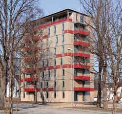
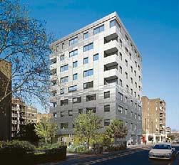
The seven-storey e 3 apartment building erected in Berlin in 2008 features elements such as timber-concrete composite slabs and an exterior reinforced concrete staircase in order to adhere to fire safety requirements (Fig. A 1.8). Eight-storey buildings that nearly qualify as high-rise structures, such as the H8 in Bad Aibling (Fig. A 1.9) and the LifeCycle Tower One in Dornbirn, followed in 2011 and 2012. The first timber building considered a high-rise, the tenstorey Murray Grove Tower, was built in London in 2009 (Fig. A 1.11). Another tenstorey apartment building, Forté Tower, was
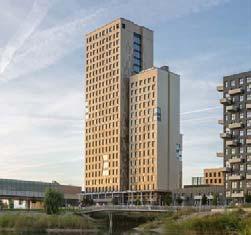
10 Tō-ji 557Japan,Temple888metresstoreys Pura Besakih Temple Bali, 11th century 44 metres 11 storeys Hopperstad stave church Norway, 1130 27 metres 4 storeys Qigu 325China,Tan1420metresstoreys Historic 721Germany,granary1445metresstoreys 10 m 20 m 30 m 40 m 50 m 60 m 70 m 80 m 90 m A 1.7 A 1.9A 1.8
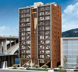
completed in Melbourne in 2012. While the building complex along the Via Cenni in Milan, completed in 2013, is only nine storeys tall, it consists of four residential towers connected by a platform building that covers an entire city block. In the United Kingdom, Australia and Italy, as in many other countries, there exist no requirements concerning the combustibility of load-bearing structures, even for high-rise buildings – as long as a degree of fire resistance is ensured for a sufficient amount of time. For this purpose, buildings can comprise encapsulated cross-laminated timber panels. A 14-storey building with a glued-laminated timber frame and prefabricated modular rooms set into its structure was built in Bergen in Norway in 2015 (Fig. A 1.12). In 2016 a student housing project with 18 storeys and a height of 53 m was completed in Vancouver in Canada, comprising a frame construction with glued-laminated timber columns and cross-laminated timber ceilings. The completion of the HoHo in Vienna and of the Mjøstårnet in Brumunddal in Norway constitute the current apex in the quest for reaching ever new record-breaking heights. The HoHo is an 80-metre tall timber-concrete hybrid high-rise building with 23 storeys (Fig. A 1.13). The Mjøstårnet consists of glued-laminated timber posts and crosslaminated timber ceilings as well as a limited number of concrete ceilings on the upper floors of the 18-storey, 84-metre tall structure. The hotel tower of the Cultural Centre in Skellefteå in Sweden reaches a height of 82 m (see project example p. 198ff.). There seems to be no end in sight for these constantly accelerating height developments, raising the question of whether the increasing effort involved justifies pushing these limits further. It proves, however, that timber meets each and every requirement placed on modern building materials. The examples from recent years outlined above show that the combustibility of timber has long been overstated and is by no means an obstacle to the construction of multiA 1.7 Apartment building – Bavarian model project, Regensburg (DE) 1996, Fink + Jocher A 1.8 e 3 high-rise apartment building, Berlin (DE) 2008, Kaden Klingbeil Architekten A 1.9 H8 high-rise apartment building, Bad Aibling (DE) 2011, Schankula Architekten A 1.10 Overview of multi-storey timber buildings according to height A 1.11 Murray Grove Tower, London (GB) 2009, Waugh Thistleton Architects A 1.12 High-rise apartment building, Bergen (NO) 2015, Artec Arkitekter / Ingeniører A 1.13 HoHo timber high-rise building, Vienna (AT) 2019, RLP Rüdiger Lainer + Partner
11 A 1.10 Cultural centre and hotel Sweden, 2021 82 metres 20 WhiteArchitects:storeysArkitekter Student ActonArchitects:1863Canada,residence2017metresstoreysOstryArchitectsArchitects:39Germany,housingDamaschkeestate1996metresstoreysFink + Jocher Germany,H8 2012 25 metres 8 SchankulaArchitects:storeys Architekten 90 m 10 m 20 m 30 m 40 m 50 m 60 m 70 m 80 Timem Forté LendleaseArchitects:1032Australia,Tower2012metresstoreys A 1.13A 1.12A 1.11 THE EVOLUTION OF MULTI-STOREY TIMBER CONSTRUCTION
• protection from weather-related low /high temperatures and moisture /dampness
• protection from interior and exterior noise exposure
32 A 5.1 Indoor Air Quality –
Maren Kohaus, Holger König
The Influence of Timber Construction
Regardless of construction type, a building must provide an indoor climate that users perceive as pleasant and must accommodate the activities it was planned for. Comfort criteria (as specified in DIN EN 15 251) offer guidance on the factors that need to be taken into account:
• sufficient ventilation for the particular use and resulting reduction of CO2 levels in the air
• protection from ionising (e.g. radon) and non-ionising radiation (e.g. electric smog)
Analyses of current testing and measuring methods that serve as basis for legal boundary values show how complex this topic is and also indicate the need for further research projects in order to synthesise results [4]. Until further findings become available, discussions on the extent to which emissions from wood and wood-based materials in contemporary timber buildings can be regarded as either harmful to health or as inherent to wood and, therefore, natural, harmless or even promoting health, are ongoing. To offer clients, users and planners a degree of security and bring clarity to the discussion, relevant aspects will be examined in detail below.
• protection from high levels of use-related moisture, resulting condensation and mould risk
• optimum lighting and adequate daylight intake, as well as protection from excessive sunlight (heat /overheating risk)
A 2003 study by the Joanneum Research Forschungsgesellschaft on the potential effects of stone pine wood in the immediate environment on people’s circulation and sleep found that it improved their performance and general well-being [2]. Maximilian Moser’s 2007 study “Schule ohne Stress” (School without Stress) analysed the effect of solid wood fittings and furnishing in classrooms. The study states that the calming effect of wood, estimated by measuring the students’ heart rates and vagal tone, might yield positive health effects [3]. The 2017 metastudy HOMERA presents an analysis of 44 research projects regarding the interrelation between emissions and wood and /or engineered wood on the one hand and indoor air quality on the other, as well as the possible effects on humans.
A Healthy Indoor Climate
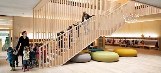
Wood has been in use as a construction material for human dwellings for centuries. Contemporary building continues to use wood and wood-based materials in a wide range of ways – as a construction material, for flooring, wall and ceiling cladding and for fittings and furnishings. The material is highly valued now as ever for its natural character and authenticity. Wood surfaces in particular, due to the specific character, colour, grain, texture and structure of the material, are generally regarded as appealing to the senses, as Maximilian Moser’s study “Interaktion Mensch und Holz” confirms [1]. Characteristics of wood specific to the material and related to building physics, such as low thermal conductivity (Å-value = 0.11– 0.17 W/mK) and low thermal effusivity coefficient or b-value (Fig. A 5.3) mean that wood surfaces are perceived as warm. Untreated wood surfaces also support the control of indoor climates, because wood enables the ab sorption of indoor air moisture and its timedelayed release. The scent of wood, which is made up of emissions of volatile substances, has a pleasantly calming effect on some people.
• poor indoor air quality due to building materials, equipment and devices A 5.1 Wood interiors, kindergarten, Bludenz (AT) 2013, Bernardo Bader, Monika Heiss – Farbe & Design A 5.2 Recommended TVOC levels and resulting recommendation for action A 5.3 Thermal effusivity coefficients of select building materials A 5.4 Classification of chemical compounds by boiling point
Adequate air exchange provided by manual or mechanical ventilation ensures that emissions produced by building products, electronic devices and by occupants are removed. However, the use of toxin-free building materials wherever possible is advised. Emissions in Indoor Air Materials used in building interiors can impact indoor air by discharging particles in the form of particulate matter and fibre or by emitting gases. User behaviour and indoor climate conditions (indoor humidity, temperature, etc.), as well as the situation and integration of construction materials into building components and their contribution to diffusion processes are relevant for levels of indoor air pollutants [5]. When discussing emissions in indoor air and wood-based materials, two terms are highly relevant: VOCs (volatile organic compounds) and formaldehyde. VOCs In both construction practice and the analysis of interiors, VOC gases are classified according to their boiling point (Fig. A 5.4): • VVOC: very volatile organic compounds • VOC: volatile organic compounds • SVOC: semi-volatile organic compounds During construction, many different VOCs are temporarily discharged into indoor air. These higher-than-usual concentrations can usually be greatly reduced by heavy ventilation during and after work. VOCs are considered a single group of substances, albeit a very diverse one. They can be harmless, become a nuisance due to their smell or even be harmful to health. The most familiar VOCs are alkane /alkene, aromatic compounds, terpenes, halogenated hydrocarbons, esters, aldehydes and ketones. Wood exudes small amounts of terpenes and aldehydes that are perceived as typical wood scent. They are termed nVOC (natural Volatile Organic Compounds) due to their origin in natural raw materials. The toxicity of different types of VOCs varies significantly. Carcinogenic benzene is a particularly harmful indoor air pollutant, while numerous VOCs, such as terpene originating in natural oils, natural colours or natural wood resin are considered comparatively harmless. In high concentrations (e.g. perceivable smell of turpentine oil), they may impair people’s well-being and be allergenic, but are not harmful to health in the concentrations usually present in timber buildings. VOC emissions from building products There are no Europe-wide statutory limits or prohibitions imposed on VOC emissions from building products. Since 2004 the AgBB evaluation scheme of the DIBt approval process, introduced by the Committee for Health-related Evaluation of Building Products (Ausschuss zur gesundheitlichen Bewertung von Bauprodukten), has served as the basis for the healthrelated evaluation of building product emissions. Updated in 2018 and adopted by the Model Administrative Provisions – Technical Building Rules (Musterverwaltungsvorschrift Technische Baubestimmungen, MVV TB) in 2019, it sets maximum emission values for building products and determines exclusion criteria according to which building products are not permitted for However,use. emissions tests of individual products should not serve to conclude what the expected indoor air concentration might be [6]. This is due to the fact that it is dependent on the influence of other factors. These factors include e.g. the situaAbbreviation Name Boiling point [°C]Examples
Recommended TVOC levels (indoor air)Hygiene assessment and recommendations for action Level 1: TVOC< 0.3 mg/m3 (< 300 μg/m3)
A gas /substance with a high boiling point is less volatile and is discharged into the surrounding atmosphere at slower rates. A gas /substance with a low boiling point is highly volatile and is therefore discharged at faster rates. Values analogous to WHO classification.
MaterialThermal effusivity coefficient b value [KJ/Km2√s] insulation (mineral fibre)0.06 cork 0.10 wood 0.4 ... 0.5 human skin 1.0 ...1.3 glass 1.3 ...1.5 water 1.6 concrete 1.8 ... 2.2 steel 14 copper 36 Materials with high thermal effusivity coefficients such as metals are perceived as cold when their temperature is lower than that of human skin. In contrast, materials with low thermal effusivity coefficients such as wood or insulation are perceived as warmer at the same temperature.
• hygienically acceptable as long as levels for individual substances are not exceeded
• hygienically unsound, occupation only for limited time periods
Level 3: TVOC> 1.0 mg/m3 (> 1,000 μg/m3 andand < 3.0 mg/m3 < 3,000 μg/m3)
VOCvolatile organic compounds50 (-100) to 240 (-260)many solvents, such as styrene and xylene
• individual toxicological evaluation recommended Level 5: TVOC> 10 mg/m3 (> 10,000 μg/m3 andand < 25.0 mg/m3 < 25,000 μg/m3)
• hygienically unacceptable, occupation to be avoided
VVOCvery volatile organic compounds 0 to 50 (-100)formaldehyde,acetone,acetaldehyde
• “target level” (= hygienic prevention range; recommended) Level 2: TVOC> 0.3 mg/m3 (> 300 μg/m3 andand < 1.0 mg/m3 < 1,000 μg/m3)
SVOCsemi volatile organic compounds 240 (-260) to 380 (-400)plasticisers, biocides, flame retardants, PCBs
INDOOR AIR QUALITY – THE INFLUENCE OF TIMBER CONSTRUCTION
• hygienically questionable, occupation only for limited time periods
• hygienically acceptable as long as levels for individual substances are not exceeded
• health impact of substances exceeding recommended levels must be tested; individual toxicological evaluation recommended Level 4: TVOC> 3.0 mg/m3 (> 3,000 μg/m3 andand < 10.0 mg/m3 < 10,000 μg/m3)
• individual toxicological evaluation recommended A TVOC concentration of more than 3,000 μg/m3 is regarded as hygienically unsound. BNB/DGNB certification only to be issued if TVOC levels are in the range of 300 μg/m3 (non-defined measurements) to 500 μg/m3 (defined measurements).
POMparticulate organic matter> 380PAH in buildingbituminousmaterials
MVOCmicrobial volatile organic compounds (produced by mould and bacteria) within VOC range wide range of different substances and substance classes
• increased ventilation necessary
33 A 5.2 A 5.3 A 5.4
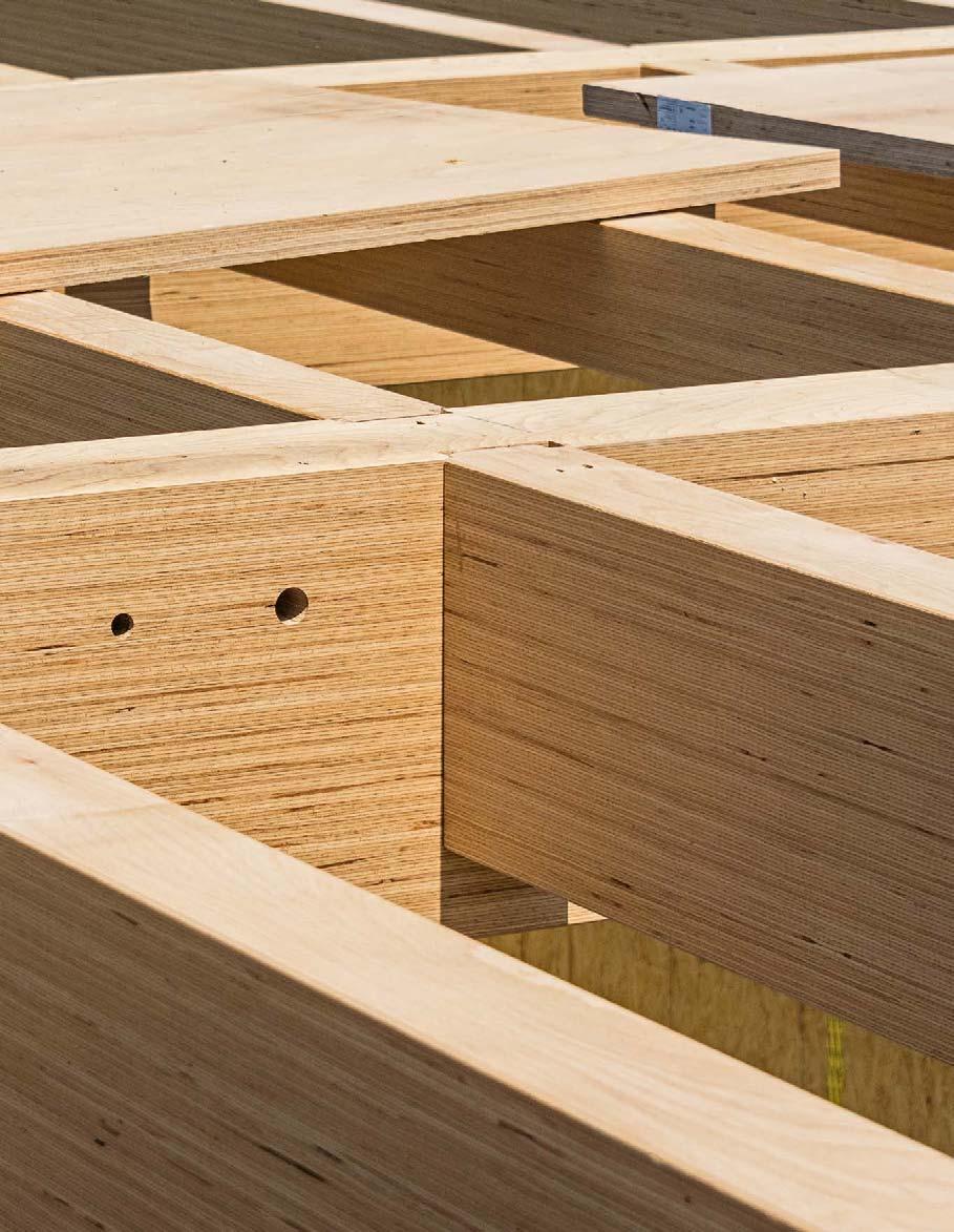
41 1 Structures and Structural Systems 42 From Linear to Planar Member 43 Combining Construction Elements 45 Combining Materials 45 Structural Engineering in Timber Construction 48 Timber Construction in Comparison 49 Conclusion 54 2 Construction Components and Elements 56 Dowel Laminated Timber Walls 57 Frame Wall Construction 58 Cross-laminated Timber Walls 60 Laminated Veneer Lumber Walls 61 Beams 62 Dowel Laminated Timber Ceilings 63 Beam Ceilings 64 Box Ceilings 66 Cross-laminated Timber Ceilings 68 Laminated Veneer Lumber Ceilings 69 Timber-Concrete Composite Ceilings 70 A Comparison of Timber Construction Elements 72 Part B Structural Systems Beech laminated veneer lumber load-bearing structure, office building, Augsburg (DE) 2015, lattkearchitekten
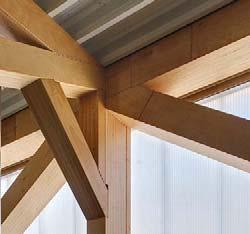
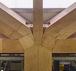
54 B 1.19 B 1.20abc fer vertical loads, new dimensions in timber construction become possible. Additional processing (hardwood-based glued laminated timber or laminated veneer lumber) can contribute to further advancements (Fig. B 1.19). For this purpose, it is also necessary to develop corresponding highperformance connections. The increasing availability of hardwood leads to new opportunities in the production of beams predominantly subject to bending forces. The elasticity modulus of such flexural construction components – and, as a result, their rigidity – does not increase to the same extent as their strength. Beech laminated veneer lumber has assumed an important role as an economically feasible construction material for trusses, which are predominantly subject to normal forces. The connection and fastening technology facility in Waldenburg is an impressive example, featuring trusses made of beech laminated veneer lumber as primary and secondary beams spanning 18.30 m to 42 m (Fig. B 1.21). Compared to steel or reinforced concrete, this permitted the creation of a structure of significantly lower weight and resulted in lower expenditure for required foundation work and assembly of the large-size beams. Fire protection requirements were also realised at substantially lower costs. The nodes between members comprise butt joints and carpentry-style woodworking joints that make use of the high lateral stress resistance and shear strength of the material. Employed comprehensively for entire structures, beech laminated veneer lumber often also finds use when specific beams or columns of a load-bearing structure are supposed to bear stronger loads without having to deviate from the dimensions of the other members of the structure. Beech laminated veneer lumber is also an interesting option for multi-storey timber frame construction if columns and beams are required to bear heavy point loads (Fig. B 1.20). The expectancy is that further timber construction materials made of hardwood or hybrid construction materials comprising softwood and hardwood will become marketable in the future. This includes, for instance, wood-reinforced timber consisting of softwood and hardwood veneer [7], hardwood cross-laminated timber or hybrid hardwood and softwood cross-laminated timber [8]. Conclusion Timber construction has undergone an astounding evolution in the last decades, accessing more and more fields of application. Building with wood has become a high-quality alternative to conventional construction methods. The combination of different timber construction types, yet also combinations of materials, by including other construction materials such as concrete or steel, allows for precise and custom solutions for very different building-related tasks. Timber buildings are becoming increasingly competitive in the context of everyday activities. Prefabrication as a specific construction process is also receiving increased appreciation. It impacts topics relevant to the future of building, such as the improvement of construction quality and speed or opportunities of digitalised and automated production processes. In addition, timber construction and its unique advantages in ecological terms offers answers to urgent societal challenges, such as energy and resource efficiency, suitability for purposes of a circular economy or climate neutrality. When architectural design and structural engineering take into account the specific characteristics of timber as a construction material while making use of hybrid construction types as required, there are hardly any limits to building with wood. IPE 270Beechveneerlaminatedlumber Beech laminatedgluedtimber Spruceveneerlaminatedlumber Spruce laminatedgluedtimber h = 270 mm w = 135 mm m = 36.1 kg/m h = 270 mm w = 160 mm m = 29.4 kg/m h = 440 mm w = 160 mm m = 48.8 kg/m h = 360 mm w = 160 mm m = 29.4 kg/m h = 460 mm w = 160 mm m = 31.3 kg/m SteelAssumptions:S235: m = 1.00 fy/x = 235 N/mm2 Beech and spruce laminated veneer lumber: use class 1 kmod = 0.9 m = 1.20 (EN 1995-1-1) Beech and spruce glued laminated timber: use class 1 kmod = 0.9 m = 1.25 (EN 1995-1-1)
STRUCTURES
AND STRUCTURAL SYSTEMS
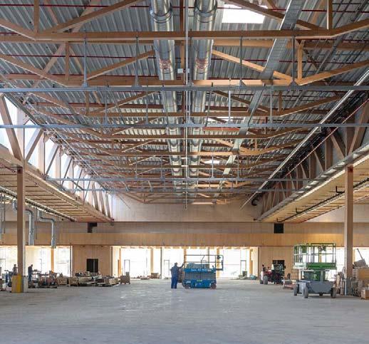
B 1.21 Connection and fastening technology production hall, Waldenburg (DE) 2020, Hermann Kaufmann + Partner a primary truss girder, supported by column, high-performance beech laminated veneer lumber woodworking joint b secondary truss girder, supported by a primary beam, woodworking joint c production hall with a roof structure comprised of primary and secondary beech laminated veneer lumber truss girders
[4] Horizontal slabs or horizontal or vertical plates are planar elements that can bear out-of-plane loads or in-plane loads; combined loading often occurs in wall, ceiling and roof elements
[5] Newcombe, M.; Pampanin, S.; Buchanan, A. H.: Governing criteria for the lateral force design of posttensioned timber buildings. WCTE 2012 Proceedings, Final Papers, Auckland 2012, p. 148ff.
[8] Kaufmann, Hermann et al.: Research project. Development of a material and energy-efficient timber construction system with hard- and softwood (LaNaSYS). Fachagentur Nachwachsende Rohstoffe (FNR), Gülzow. Termination date 06/2023. www.ar.tum.de and www.bgu.tum.de
55 c b B 1.21
[6] Wanninger, Flavio; Franghi, Andrea: Experimental and analytical analysis of a post-tensioned timber frame under horizontal loads. Engineering Structures, Vol. 113, Kidlington 2016, p. 16 – 25 [7] Lechner, Markus; Winter, Stefan: Hybride Holzbauteile aus Laubholz-Furnieren und Brettschichtholz aus Nadelholz – Holzbewehrtes Holz. Research project Technical University of Munich. Bundesinstitut für Bau-, Stadt- und Raumforschung (BBSR), Bonn, Research initiative “Zukunft Bau”; SWD10.08.18.7-18.21. Termination date 06/2021
B 1.19 Comparison of different glued laminated timber and laminated veneer lumber (beech and spruce) column cross sections with a steel IPE 270 Å-beam
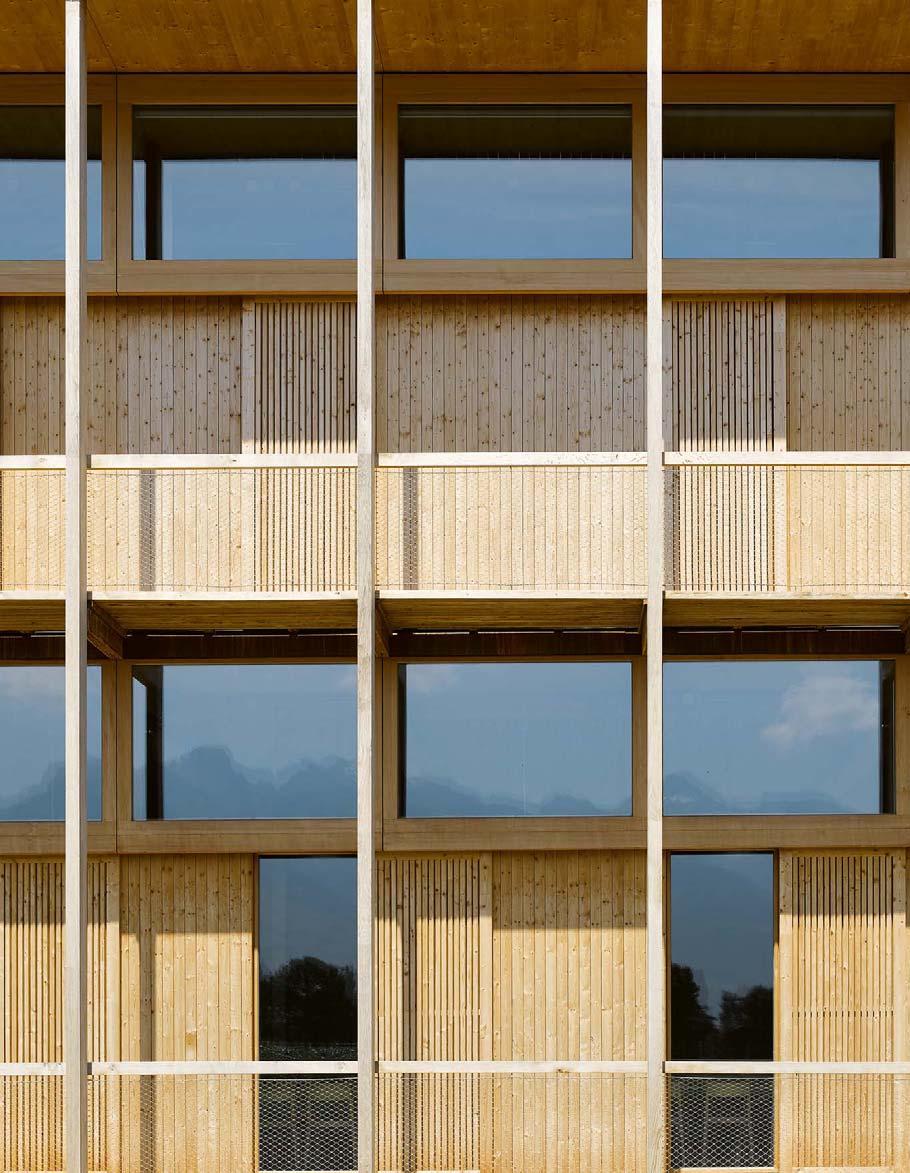
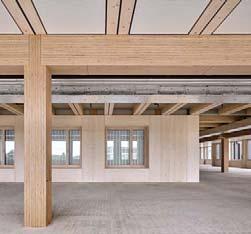
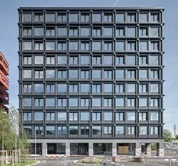
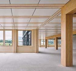
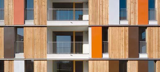
B 1.20 Nine-storey administration building, RischRotkreuz (CH) 2018, Burkard Meyer Architekten a, b timber-concrete composite beam ceiling with beech laminated veneer lumber primary frame construction (columns /downstand beams) c The facade visually displays the frame construction and the rhythm of structural members.
Notes: [1] Deplazes, Andrea: Holz indifferent, synthetisch. In: DETAIL 1/2000, p. 23 [2] CEN / TS 19 103 Design of Timber Structures –Structural design of timber-concrete composite structures – Common rules and rules for buildings www.bgu.tum.de [3] Basic rules of stiffening: at least one ceiling plane is connected to three wall planes with their axes not intersecting in one point, or four wall planes with their axes intersecting in at least two points.
In-plane stiffness The in-plane stiffness of frame construction and dowel laminated timber walls is minor compared to that of relatively homogeneous cross-laminated timber and laminated veneer lumber walls, the performance of which is sufficient to stiffen taller buildings.
A Comparison of Timber Construction Elements constructionframetimberlaminateddowel timberlaminatedcross- lumberveneerlaminatedglued stackedlaminatedboards low high low high 0 % 3 % load-bearing capacity In-plane stiffness Additives (glue percentage) constructionframe boardsstacked frame construction with continuous studs timberlaminatedcross- lumberveneerlaminated lumberveneerlaminated dowelled dowellaminatedcross-timberlaminated timber frame construction with diagonal sheathing frame construction with OSB sheathingboardsstackedlaminatedglued timberlaminatedcrossWall elements
The figures B 2.63– B.2.66 compare the structural components described above (p. 51–71) based on the following parameters. Load-bearing capacity As a rule, common frame construction walls are not suitable for buildings taller than three storeys, unless built according to a specific construction type (Figs. B 1.11 b and c, p. 48). Cross-laminated timber, laminated veneer lumber and, most of all, dowel laminated timber walls can bear very heavy vertical loads and are, therefore, suitable for erecting tall buildings.
72 B 2.63
Additives Adhesives comprise the majority of additives for wood-based materials, construction components and elements. Using hardwood dowels as connectors enables the creation of adhesive-free dowel laminated timber and cross-laminated timber walls, as well as dowel laminated timber ceilings. The same applies to frame construction walls and beam ceilings, where the stiffening function is achieved by diagonally arranged boards, instead of woodbased material panels (three-ply panels, OSB, etc.). Spans Beam ceilings are seldom used for multistorey timber buildings and only for relatively short spans. In most applications, vibration and flexural behaviour are de cisive for dimensioning construction components, rather than load-bearing capacity. Therefore, cross-laminated timber and dowel laminated timber ceilings are suitable for average spans, while timber-concrete composite ceilings and box ceilings are appropriate for long spans.
73 B 2.64 A COMPARISON OF TIMBER CONSTRUCTION ELEMENTS 5 m 10 m 0 % 3 % low high Span CO2 storage capacity Additives (percentage of glue) beam ceilingbox ceiling stackedveneerlaminatedbeech,boards softwoodveneerlaminated timberlaminatedcrossbox ceiling beam ceiling veneerlaminatedbeechboardsstacked softwoodveneerlaminated timberlaminatedcrossbeam ceiling timbercross-laminatedunidirectional bidirectional crosslaminated timber, stacked boards box compositetimber-concreteceiling,ceiling timber-concrete composite ceiling, bidirectional crosslaminated timber, timberconcrete composite ceilingdowel laminated timber box ceiling with laminated veneer lumber sheathing lumberveneerlaminateddowel withtimber,laminatedbeamceilingboardsheathing beam ceiling with OSB laminatedboards,gluedsheathing,stackedcross-timber 0.08 m3/m2 0.22 m3/m2Required material Ceiling elements
Combustibility plays a major role in the ignition and growth phases of a fire. Thus, prescriptive building regulations feature requirements for non-combustibility of surfaces in emergency escape routes (e.g. in staircases and corridors) or the provision to use low-combustibility building materials as facade cladding, in order to meet the general performance requirements described above. New research [4]
It is imperative to clearly distinguish between the combustibility of building materials (defined in building material classes) and the fire resistance of construction components (defined by the fire resistance classes of construction components). The combustibility of building materials essentially influences the spread of fire immediately after ignition and as it develops. DIN 4102 divides building materials into non-combustible (A1 and A 2) and combustible materials classes (B 1 to B 3). DIN EN 13 501 specifies seven “Euroclasses” (A1, A 2, B, C, D, E, F) and classes s1, s2 and s3 for smoke emission (s = smoke), for burning droplets (d = droplets) classes d 0, d1 and d 2 and special classes for floorings (fl = floorings) (Fig. C 1.3, p. 79). The fire resistance of a construction component describes its capacity to remain stable (criterion R) and the capacity of a construction component that encloses spaces to prevent the transmission of smoke and fumes (criterion E), as well as heat (criterion I) for the required fire-resistance duration. Construction components are classified in fire resistance classes, which use the building authority terms “fire-retardant”, “highly fire-retardant” and “fire-resistant”, according to duration of fire resistance (specified in 30-minute intervals) (Fig. C 1.4, p. 79). Load-bearing structural elements may also enclose spaces, e.g. party walls between residential units (REI), while individual columns only need to be designed to retain their structural integrity (R). Figure C 1.5 shows the principles of fire development and allocation of the requirements outlined above.
• A pane of glass is not combustible, but heat passes through it almost immediately. While a 30-mm thick softwood fibre panel can burn, it can significantly obstruct heat transmission, preventing an increase in temperature on the side not exposed to the fire for up to 15 minutes.
Combustibility and fire resistance
• A steel column (class A building material – non-combustible) that is neither protected by fire protection cladding nor fire protection coating typically loses its load-bearing capacity after 30 minutes. In contrast, a glued laminated timber column will burn on its exterior, but can retain its structural integrity for more than 90 minutes in a fire, without any additional protective cladding or coating.
RisksfireDiagram,development
DIN EN 13 501-2 fire behaviour classification of construction products and types – fire resistance tests
Fire behaviour of combustible construction components or structures Fire behaviour of non-combustible construction components or structures
Test standard DIN EN 13 501-1 fire behaviour classification of construction products and types – fire behaviour of construction products
80 fire outbreakignition flashover full-scale fire REI 30REI 90coolingfire growth time 30 min90 min temperature C 1.5 buildings (high-rise buildings with a topmost floor elevation of more than 22 metres above ground): firefighters may be unable to effectively extinguish fires above these heights. Such buildings should be able to withstand a complete burnout without their load-bearing structure collapsing. The related special building regulation prescribes a fire resistance of at least 90 minutes and the use of non-combustible construction materials for high-rise buildings. Their structural components are required to maintain their long-term load-bearing functions, even in the post-fire cooling phase [3]. The 90-minute period is calculated based on an average fire load in residential and office buildings of 600 to 750 MJ/m2, which a fully ventilated fire has typically consumed in 90 minutes, i.e. the temperature in the impacted space falls relatively quickly to below 200 °C in the cooling phase (Fig. C 1.5).
Building authority designation adjoining building materials taken into accountfire-retardant fire-resistant
combustibilityspread of flames on surfacesbuilding materials: heat build-up, smoke and toxicity construction components: load-bearing capacity (R), partition (E; flame passage, residual strength) and heat transition (I)
The combustibility of a building material and the fire resistance of a construction component are not directly related. Some examples that illustrate this fact include:
C 1.7 Combustion behaviour of various timber building materials as per DIN EN 1995-1-2 fire can’t penetrate into cavities where it could spread unchecked and become almost inaccessible to firefighters. Burning solid timber elements are easy to extinguish, no subsequent ignition occurs. This makes it possible, and in many cases has been achieved, to install solid and visible timber construction elements with a fire resistance duration of 90 minutes (REI 90) in buildings below high-rise height and use them as an alternative to firewalls in staircases (REI 90-M; see “Administration Building in Aalen”, p. 237ff.).
C 1.5 Diagram of fire development showing the influence of building materials and construction components C 1.6 Cross section of a solid timber beam exposed to fire. In contrast to the one-dimensional burn rate ß0, which measures the burn-off depth in the centre of a timber cross section, the nominal burn rate ßn takes the rounding of corners in the burning of cross sections and timber cracks into account.
• The necessary corridors and staircases must be kept free of fire loads by means of non-combustible cladding or panelling.
• The share of exposed timber surfaces in individual rooms should be limited to minimise the increase of the fire load through timber construction elements. The rule of thumb to limit non-mobile fire loads is: in the case of a ceiling comprised of visibly exposed solid timber construction components, walls must not be clad in combustible materials. Alternatively, up to 25 % of wall surfaces can consist of exposed solid timber, as long as the ceiling underside is not clad in combustible materials. Additional and individual non-clad columns or downstand beams are permissible. The surface exposed to fire must not comprise more than 40 % of the overall wall surface, or in the case of an exposed timber ceiling, the flammable surface must not be increased by more than an equivalent of 25 % of the ceiling surface. For typical screed construction using nonMaterial One-dimensionalburnrateß0[mm/min] burnNominalrateßn[mm/min]
81 C 1.7 C 1.6 PROTECTIVE FUNCTIONS confirms the influence of exposed timber construction components on fire development. In particular in the case of multistorey residential buildings, restrictions are necessary and are formulated within policy, for instance the new model timber construction directive (Muster-Holzbaurichtlinie, MHolzBauRL) [5]. Timber construction performance characteristics A timber building must ensure the same levels of safety as other construction types. The fire behaviour of timber and timber structures must be realistically assessed, regardless of combustibility, to utilise the positive properties of the material in the event of fire. The basic fire safety performance requirements (see p. 78f.) for all structures must be equally met by timber structures. Planners, clients and others involved in the construction of timber buildings often want to create exposed wood surfaces (at least in some areas). Thus, the combustibility of the material in particular must be taken into account. The behaviour of timber construction elements in a fire is greatly influenced by the interrelation between surface to cross section and the densities of various species of wood. The greater the density of wood, the lower its burnout rate, i.e. the burnout in mm/min when impacted by fire (Fig. C 1.7). Burning timber contributes to the indoor fire load. On the side exposed to the fire, a charred layer forms that also protects the interior area it borders. The nominal char rate ßn takes increased charring of corners into account (Fig. C 1.6). Also, the thermal conductivity coefficient of wood is relatively low (≤ 0.13 – 0.17 W/mK). Thus, the inner, unburnt area remains cool and maintains load-bearing functions. Increasing the thickness of components beyond the structurally required dimensions can provide effective timber fire protection cladding. Another advantage of solid timber elements is that
Softwood and beech glued laminated timber with a characteristic bulk density of ≥ 290 kg/m3 solid timber with a characteristic bulk density of ≥ 290 kg/m3 0.650.65 0.80.7
solid wood or glued laminated timber with a characteristic bulk density of ≥ 450 kg/m3 0.500.65 0.550.7
• Fire protection cladding for a defined protection period (encapsulation criterion, e.g. K 230 or K 260) limits the temperature on the side not exposed to fire within the period specified to T ≤ 300 °C and, thus, prevents the timber from burning and increasing the fire load. Encapsulation cladding in the case of frame construction with insulated or insulation-free cavities must also prevent fire from penetrating into a structure.
Hardwood solid wood or glued laminated timber with a characteristic bulk density of ≥ 290 kg/m3
Panels wood wood-basedplywoodpanellingpanels, except plywood 0.9 1) 1.0 1) 0.9 1) 1) Figures apply to characteristic bulk density of 450 kg/m3 and material thickness of 20 mm.
Planning for fire protection in the case of timber construction requires particular consideration of the following criteria:
Laminated veneer lumber with a characteristic bulk density of ≥ 480 kg/m3 0.65 0.7
• condensation protection (due to convection or diffusion)
• load-bearing / structural layer
• fire safety • soundproofing (incl. acoustic measures) Facades and roofs are subject to basically identical building physics requirements, although different functional requirements will call for different sequences of layers and materials in related construction components. To effectively manage the complexity of the functional allocation of individual layers of components, it is advisable to identify their functions in the early planning stages and specify them in detail plans and workshop drawings (Figs. C 3.4 and C 3.5, p. 100).
Building RequirementsEnvelope
• exterior cladding
• insulation layer • airtight layer • vapour barrier layer
• windproof layer / second water-bearing layer
• installation layer (with / without insulation)
• interior cladding or panelling Each function within a construction component can be assigned to a specific layer, but some materials are polyfunctional and can perform several functions at the same time (Fig. C 3.3). A vapour barrier layer and airtight layer are typically incorporated into the same layer of a component, e.g. a wood-based material panel or film layer. Allocating functional requirements to component layers requires their continuity, which must be considered when creating joints and connections between components. An exposed cross-laminated C 3.1 Low-energy timber houses, Mühlweg residential development, Vienna (AT) 2006, Architekten Hermann Kaufmann C 3.2
Building envelopes must perform the following protective functions (see also “Protective Functions”, p. 78ff.):
• weather protection (wind, rain, snow, sun / UV radiation) • thermal insulation in winter / summer • airtightness
Building envelope construction layer development in timber construction (horizontal section) with focus on thermal insulation C 3.3 Polyfunctionality of construction component layers
98 C 3.1
The Layer Structure of Building Envelopes Maren HermannKohaus,Kaufmann
Modern timber construction, given the special opportunities offered by wood as a natural, renewable building material, plays a pioneering role in environmentallyfriendly construction. Many passive energy and plus-energy buildings feature highly insulated building envelopes based on a timber construction type. Concerns related to past experiences with draughty interiors quickly overheating in summer are now unfounded. In fact, the opposite is the case. Timber construction offers a very effective means of achieving a low heat transmission coefficient with thin walls (Fig. C 3.2), as the many timber buildings that meet modern comfort standards prove. These advantages are being acknowledged not only in new buildings, but in renovated buildings as well. With the opportunities offered by prefabrication, building envelope systems based on timber structures increasingly find acceptance. The complex layer composition of timber structures, however, places high demands on planners and the professional execution of construction elements. As the number of layers of construction elements increases, the complexity of joints between elements in prefabricated structures in particular does so as well. Therefore, reducing the number of layers is considered a sensible aim (see “Building Simpler”, p. 118). Efforts are ongoing to control the variety of possible solutions through standardisation in order to achieve a better overview and greater planning reliability [1].
Functions of Construction Component Layers
Individual layers are described in accordance with their functions as follows:
timber panel of an exterior wall that has a load-bearing function can also serve as a vapour barrier and airtight layer. In this case, joints between elements must be tightly sealed. This can be achieved by covering joints with sealing tape or placing sealing strips between joints or into gaps (Fig. C 3.12, p. 103). Polyfunctional layers of construction components generally make it possible to reduce the number of layers and result in a reduced workflow in executing components. This reduction, however, usually also requires special connection details between components (e.g. by integrating interior components or service lines into the building envelope). Careful planning and monitoring in the construction phase are therefore important. Insulating layer and construction A principal distinction is made between two different types of primary insulation levels, in terms of construction and depending on their position in relation to the structure. Insulation can be placed either on the outside of the load-bearing structure, which is usually the case with solid timber structures comprised of cross-laminated, dowel laminated or glued laminated timber elements (Fig. C 3.13, p. 104), or it can be infilled between linear structural members (Fig. C 3.14, p. 105).
Structures with exterior insulation Rigid insulating materials that do not require a dedicated substructure are typically used for structures insulated on the outside. Soft insulating materials, in contrast, are infilled between a single, double or even three-layer substructure (Fig. C 3.9, p. 102) with members arranged crosswise, or between special members optimised for minimal thermal bridges (e.g. Å-joists) (Fig. C 3.13 a, E, p. 104).
2 mm sanded stainless sheet steel substructure back vapour-permeableventilation facade membrane 380 mm three-ply mineral wool e.g. 72 mm cross-laminated timber element, adhesively sealed edges, airtight joints, interior exposed timber quality
99 Exterior wall protective functions Exterior wall construction component layers Exterior wall functional layers 4polyfunctionality:functionscorrespond to 1 construction component layer sarking (windproofing,layer second water-bearing layer) claddingexterior thermal (rigid/soft)insulation structural load bearing layer barriervapourlayerairtight interior (with/withoutcladding installation layer) insulationthermal condensationprotectionprotectionfire proofingsound- acousticsairtight-nessprotectionweather °C exteriorinterior Example exterior wall structures cm38.40 timber structureframe U = 0.16 W/m2K cm42.25 solid timber structure (here: Utimber)cross-laminated=0.16W/m2K 1972 U = 0.58 W/m2K cm17.85 1982 U = 0.28 W/m2K cm22.45 1992 U = 0.25 W/m2K cm26.15 2002 U = 0.18 W/m2K cm28.75 C 3.2 C 3.3 THE LAYER STRUCTURE OF BUILDING ENVELOPES
It is both possible and probable that the combination of timber with other building materials, primarily concrete and reinforced concrete, will see further developments. Solutions are already available in the form of hybrid construction components, such as timber concrete composite ceilings that include shared prefabrication processes for both materials. Some construction types allow for intelligent combinations of elements prefabricated separately according to particular materials on the building site (see “Timber-Concrete Composite Ceilings”, p. 70f.), in response to the available, yet different options specific to construction companies and trades. The integration of different trades in the context of assembly has, thus far, not been practised exhaustively. Building components made of mineral materials, such as firewalls or stiffening access cores, are typically built independently of timber construction, even where prefabricated reinforced concrete elements are used. This significantly slows down the construction process and increases the cost and complexity required for scaffolding. The reason for this lack of integration is less due to construction-related obstacles and more due to the typical contemporary separation of trades into one construction company carrying out execution for concrete and another for timber construction and the resulting organisation on the building site (e.g. crane use). In Central Europe, there is an ongoing trend of large firms serving as general contractor merging with timber construction companies with the aim of securing a share in the promising future timber construction market. As a result, there is a likelihood of the creation of companies underpinning hybrid construction
a final step, panels with integrated sealing strips were attached to the inside, completing the airtight and vapour barrier layers. The example of two element joint alternatives in the case of a facade renovation project with wall framing elements in Fig. D 4.14 shows how assembly process and prefabrication influence the design of details. In the case of a residential building renovation in Augsburg (see p. 228ff.), floor-to-floor height elements were connected with screws and the timber frame structure was geometrically interlocked, which also led to minimising thermal bridges (Fig. D 4.14 a). In the renovation of a residential and office building in Munich, extensive metal cladding projecting beyond elements did not permit this type of solution. The elements were set into position from above, stacked on top of each other, and connected by hardwood dowels (Fig. D 4.14 b). The structure was completed once the element was lifted into place. No further connection was necessary along the edges of the building structure.
tial for combining space-enclosing and planar elements when adding further storeys and horizontal extensions to buildings while they are still in use.
Combinations of different prefabrication steps Similar to the simultaneous use of different timber construction types, the combination of different prefabrication steps offers potential that has, thus far, been scarcely exploited. Modular construction is a suitable method for room modules that are comparatively small and feature a high degree of technical installation and building services technology or complex equipment, such as kitchens, sanitary rooms or also access cores. In contrast, planar or linear elements demonstrate ideal suitability for flexible and open spatial structures with long spans. By intelligently combining systems, buildings become possible that can be assembled quickly with a high degree of flexibility and a maximum degree of prefabrication. Another application of this method is suitable for elegantly solving the central problem of renovating bathrooms in residential buildings, by adding replaceable modules that are accessible from the building exterior. There may also be great poten-
168 D 4.12ba D 4.13
Hybrid construction types
Room modules in timber construction have been realised in Germany since the 1970s. Initially only used for single-storey buildings, multi-storey timber room module buildings have been built since the 1990s, most of all, in the Vorarlberg state of Austria and in Switzerland. A maximum degree of prefabrication was employed for early projects by adding storeys to hotel structures with minimal permitted downtime (e.g. Hotel Fetz in the Bödele ski resort, by Leopold Kaufmann, 1997). The construction of the five-storey Hotel Ammerwald near Reutte in 2009 is considered a milestone in the development of timber room module construction types. With 96 modules, it constitutes an entirely new dimension of this construction type. From 2010 onward, projects exceeding high-rise limits were built all over the world. The market share of timber room module construction is currently increasing and plays a strong role in the range of different timber construction types. Design and typology Room module construction has a significant influence on the logic of spatial organisation (Fig. D 4.15). Transport and load-bearing characteristics are the most influential limiting factors. The typical application of room modules encompasses construction tasks for small, enclosed and repetitive functional units, such as apartments, senior care facilities or hotels. In these cases, a degree of prefabrication of 100 % is possible. Modules are, under ideal circumstances, delivered to the construction site complete with furniture, locked entrance door and only to be opened after inspection. Beyond this typical field of application, there is a tendency towards utilising transport sizes as much as possible and organising entire apartments within a spatial module. Larger apartments can be created by connecting multiple room modules. In school construction in particular, large rooms, such as classrooms, are mostly assembled from three-room modules that allow individual transport (Fig. D 4.9, p. 166). In the case of these open room modules, the degree of prefabrication is somewhat lower. Flooring needs to be applied on site.
In structural terms, the application type occurring most often includes precisely stacked room modules with primary loadbearing capacity (Fig. D 4.17, p. 170). However, self-load-bearing room modules for placement within a primary structure are also available. In addition, combinations are possible: in the case of the residential timber high-rise building Treet in Bergen in Norway, already the world's tallest timber building during construction in 2015, four storeys of room modules were stacked on top of each other altogether three times and placed into a large-scale glued laminated timber exoskeleton (Fig. A 1.12, p. 11). This module for a modulesanitarymoduleapartmentcompletewithroom=room two open e.g.combinedmultipleancombinedmodulesintoe.g.officeroommodulesintoclassrooms
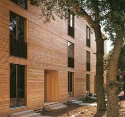
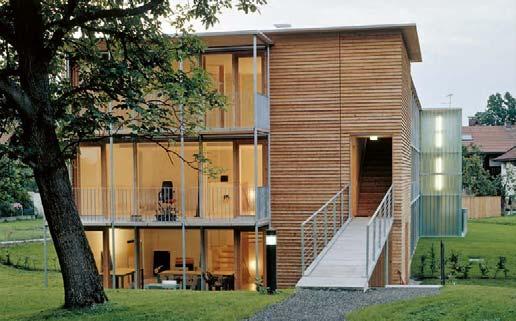
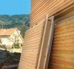
169 D 4.14ba D 4.15 PREFABRICATION D 4.12 Ölzbündt housing development, Dornbirn (AT) 1997, Architekten Hermann Kaufmann, Christian Lenz a Prefabricated facade element on site b High degree of prefabrication, horizontal section, element joint, exterior wall, scale 1:20 D 4.13 Facade design revealing prefabrication, housing development in Dornbirn (AT) 1997, Architekten Hermann Kaufmann, Christian Lenz D 4.14 Facade modernisation through prefabrication, vertical cross section, element joint a Cladding allows for screw connections along front edge, renovation of a residential building, Augsburg (DE) 2012, lattkearchitekten b Cladding does not allow for screw connections along front edge, residential and office building, Munich (DE) 2016, Braun Krötsch Architekten D 4.15 Typology of room modules: interrelation room –module types with a corresponding corporate structure, which then will significantly accelerate the construction process for hybrid buildings. Maximum Prefabrication: Room Module Construction Types
232 12
272 21 Fink
284 24 Andy
276 22 Sauerbruch
250 16 Bruno
224 10 lattkearchitekten,
183 Part E Examples of Buildings in Detail E1 Joinery in Detail 184 01 Acton Ostry Architects, Student Residence in Vancouver 190 02 Kaden Klingbeil Architekten, Residential and Office Building in Berlin 194 03 White Arkitekter, Cultural Centre and Hotel in Skellefteå 198 04 pool Architekten, Residential and Commercial Building in Zurich 204 05 OOPEAA, Residential Complex in Jyväskylä 208 06 Deppisch Architekten, Residential Complex in Ansbach 212 07 ARGE ArchitekturWerkstatt Vallentin, Johannes Kaufmann Architektur, Residential Complex in Munich 218 08
Florian Nagler Architekten, Residential Development in Munich echsle architekten, Rooftop Extension in Zurich Renovation of a Residential Building in Augsburg Mühlethaler, Residential Buildings in Zurich
237 13 Architekten
246 15 Michael
254 17 Cukrowicz
262 19 NKBAK,
288 25 Helen
294 Residential
228 11 Rolf
220 09 spillmann
Florian Nagler Architekten (System Development and Design), Kampa (Construction), Administration Building in Aalen Hermann Kaufmann, Office Building in Vandans Office Building in St. Johann in Tyrol Green Architecture, Research and Office Building in Prince George Mader, Administrative Building in Clermont-Ferrand Nachbaur Architekten, Community Centre in St. Gerold Diedorf – Architekten Hermann Kaufmann, Florian Nagler Architekten, Secondary School in Diedorf European School in Frankfurt am Main R2K, School Complex in Limeil-Brévannes Thurnher, Agricultural Training Centre in Altmünster Hutton, Student Housing in Hamburg Architekten, Office Building in Alpnach Senn Architekt, Agricultural Centre in Salez & Hard and SAAHA, Bank Headquarters in Stavanger complex in Jyväskylä (FI) 2015, OOPEAA
240 14 architekturwerkstatt,
280 23 SEILERLINHART
268 20 Agence
258 18 ARGE
The connection between a ceiling slab and a load-bearing exterior wall displays the interdependencies of joining construction components in multi-storey timber buildings particularly well. The continuity of exterior wall layers belonging to the thermal building envelope and slab structures as separation between floors must be coordinated with the slab supports and the transfer of loads from floors above. These parameters are superimposed by specific principles resulting from prefabrication and construction processes. The taller a building is, the more decisive a standard detail that is repeated floor by floor will become to its structure. As an introduction to the documentation of projects, this chapter features a comparison of slab support details along exterior walls of five very different timber buildings. The office building in Vandans and the community centre in St. Gerold comprise frame structures that could hardly be more different in terms of their functional requirements, slab structures and assembly processes. The load-bearing structures of the Woodie student housing project and the agricultural centre in Salez consist of cross-laminated timber wall and ceiling plates. They are, however, fundamentally different buildings: on the one hand, apartments were prefabricated as room modules, on the other hand, boarding school rooms were built as conventional wall and ceiling elements. These examples are compared with a residential complex in Zurich comprising multi-storey structures with load-bearing wall framing Whileelements.the projects are described in detail and comprehensively illustrated in the project documentation section, one specific detail will be compared here – the connection between the ceiling and the exterior wall. Each of these joinery examples – similar to the key topics of Parts B, C and D of this Manual – is analysed in terms of principles of load-bearing structure, structural engineering and construction process and discussed in the context of the overall system of each building.
The opportunities to combine various loadbearing systems, the multilayered character of construction components, different types and degrees of prefabrication and continuously growing requirements placed on construction types result in very complex and specific detail manifestations. Self-explanatory, generally applicable – if possible, standardised – forms of execution are still the exception, rather than the rule in timber construction. When a load-bearing structure is designed to remain visible, technical aspects of joints that connect construction components are deeply entwined with design intentions.
184Joinery in Detail
Stefan Krötsch
Detail 1
The wall framing elements feature two layers of insulation. The interior sheathing layer comprises adhesively bonded joints and includes the airtight layer. It is continued along and around the integrated ceiling elements and is adhesively bonded to the sheathing in the area of the floor construction. Short, projecting roof elements protect the timber facade and windows from weathering. The sound insulation and fire safety requirements of the ceiling slabs are met by a layer of floating screed above and a hung ceiling below.
185JOINERY IN DETAIL
Structural engineering
Prefabrication and assembly
Layer composition
The load-bearing exterior walls consist of wall framing elements. An edge beam with L-shaped cross section is placed on top of studs and into a recess along the upper edge of the wall elements. It serves as a linear support for the dowel laminated timber slab elements. The wall elements feature neither top nor bottom plates, studs are continuous along the entire height of the wall element. Vertical loads are transferred through element joints, settlement-free and without transverse compression applied to timber components, from one stud end grain to the next stud end grain.
Wall framing element – dowel laminated timber ceiling Residential Buildings in Zurich Project documentation p. 232ff. Isometric illustrations, n.t.s. Vertical sections, scale 1:50
The panel elements were prefabricated including windows, sun protection devices, interior finishes, cladding substructure and window soffits as construction components allowing integration of four windows each. The prefabricated floor-height exterior wall cladding panels and projecting roof elements were mounted on site. After erecting wall elements, ceiling elements were placed on top with a timber batten as a guide along their top edge, serving to fit in the successive wall element equipped with a corresponding recess along its lower edge.
WhiteArchitects:Arkitekter, Stockholm Robert Schmitz, Oskar Norelius Structural engineering: TK Botnia, Burträsk Text: Stefan Krötsch
Concept
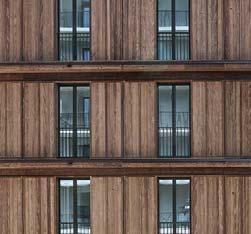
The Swedish city of Skellefteå, home to about 35,000 residents, is 770 km north of Stockholm on the Gulf of Bothnia. With a floor area of roughly 28,000 m2, a height of approximately 82 m and a footprint of 60 ≈ 160 m, the Sara Cultural Center, named after the Swedish author Sara Lidman, constitutes one of the world's largest timber buildings. The building complex unites different cultural functions and, thus, comprises the new centre of the city. It houses multiple theatre stages and public event spaces, a concert hall, an art museum, an art gallery, studios for dance and ballet, the municipal library, as well as a hotel with conference centre. The building geometry, an addition of multiple volumes, sculpturally represents the functional heterogeneity. The hotel, a slender high-rise structure, towers above the cultural centre and offers a panoramic view of the Nordic forest landscape beyond the city limits. Along the facade and in the interiors, the surfaces consist almost exclusively of timber. This creates a comfortable atmosphere most of all during the long, dark subarctic winters. The extensively glazed foyer in the southwest of the building and the exhibition spaces offering views to the interior in the north-east provide transparency and connect spaces inside the building with the surrounding environment. The galleries and the grand staircase with its sitting steps provide the foyer with a character resembling a market place. The execution of a building ensemble of this size and complexity almost exclusively as a timber structure is, for one, indebted to the ecological aspirations of both the client and the planners. In addition, it reflects local building traditions and serves to integrate the timber processing industry, important to the region, within the project.
198Cultural Centre and Hotel Skellefteå, SE 2021
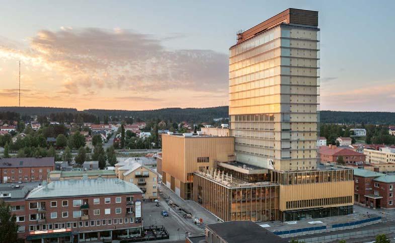
199 9 11 10 12 87 5 6 4 321 a a 13 1514 19 20 16 2121817 22 2423 CULTURAL CENTRE AND HOTEL IN SKELLEFTE Site 21ScaleFloorScaleplan1:3,000plans1:750LibraryMainfoyer with “cultural staircase” 3 Cloakroom 4 Matinee stage 5 Hotel lobby 6 Reception 7 Hotel kitchen 8 Hotel auxiliary room 9 Building services centre 10 Ventilation centre 11 Store / library 12 Storage rooms 13 Studio 14 Carpentry 15 Smithy 16 Theatre hall (small) 17 Auditorium 18 Foyer 19 Theatre hall (large) 20 Concert hall 21 Upper foyer 22 Kitchen 23 Exhibition space 24 Hotel room 6th –18th floor Ground floor First floor
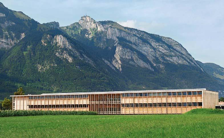
Salez, a village in the Rhine valley with a population of 830, is located only a few kilometres from the border between Switzerland and Liechtenstein. The Swiss canton St. Gallen has operated a training centre for agricultural professions here since the 1970s. The existing building ensemble housing administration and workshops was expanded by an L-shaped addition. The two-storey, longitudinal main wing contains rooms for education and training, while a three-storey wing comprises the boarding school dormitory and guest apartments.
Structural engineering: merz kley partner, Altenrhein Text: Stefan Krötsch
288Concept
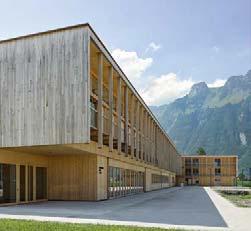
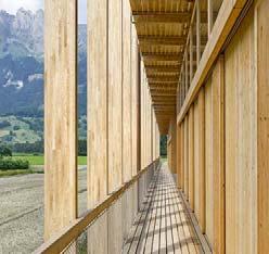
As a result, an elongated courtyard was created between the new construction and the existing buildings. The two entrances to the new addition are located on the courtyard side at the interface between the education and dormitory wings and at the eastern end of the main longitudinal wing. In the interior, staircases and double-height rooms provide interruptions and changes in orientation to the otherwise strictly linear organisation of the building. Access balconies in front of the south and west facades provide structural sun protection. Together with the access balconies on the north side of the building, they vividly express the rhythm of the load-bearing structure with its uninterrupted 2.14-m grid and define the appearance of the building. A central incision on the building volume’s southern side creates space for a covered and, in parts, two-storey terrace that offers gorgeous views towards the surrounding landscape of the Rhine Valley.
Structural Engineering The two-storey, longitudinal main education wing comprises a skeleton frame structure with spruce glued laminate timber columns and beams. Ceiling elements consisting of Agricultural Centre Salez, CH AndyArchitects:2019SennArchitekt, St. Gallen
7 Fitness 8 Double room 9 apartmentJanitor’s 10 First aid room 11 Cloakroom 12 Delivery 13 Kitchen 14 Food counter 15 Auditorium 16 Group room
The large concrete mass allows maintaining soundproofing requirements between floors of the education wing and also serves as thermal storage mass. The three-storey dormitory wing is based on the same construction grid as the main longitudinal wing. Due to the shorter spans, a parallel shear wall construction based on cross-laminated timber panels finds use, with the primary span oriented parallel to the longitudinal facades. For reasons of soundproofing, load-bearing walls between dormitory rooms are built as cavity walls. As in the school facility, timber concrete composite ceilings featuring cross-laminated timber and in-situ concrete span from wall to wall. To prevent sound transmission between storeys, ceilings are separated by a gap, similar to the walls. To create a ceiling plate that stiffens the entire building, ceiling segments are connected by three steel flanges each placed between the cross-laminated timber and the concrete layer.
Structural Timber Protection
289AGRICULTURAL CENTRE IN SALEZ 6 6 8 6 64 9 16 1676543168 9 10 1112 13 1514 1 2 aa bb1 aa Site SectionScaleplan1:4000•Floor plans Scale 1:750 1 Entrance / vestibule 2 Dining hall 3 Terrace 4 Recreation 5 Teaching kitchen 6 Training room
6-cm thick three-layer panels are set into this frame. Combined with a 10-cm thick layer of in-situ concrete, they constitute a timber-concrete composite construction. This composite construction forms a stiff ceiling plate and ensures necessary stiffness for ceilings spanning up to 8.50 m.
In order to ensure that the weathered access balconies remain functional as long as possible, all structural components consist of oak. In addition, the construction is suspended from a cross-laminated timber panel that projects from the roof, which prefents splash or surface water penetration. A steel edge beam enables linear distribution of point loads from the tensile oak glued laminated timber posts into the cantilevering panel. The oak decking is placed indirectly on top of beams, which feature slotted plate spacers as connectors Ground floor 1st floor
Hermann Kaufmann born Univ.-Prof.1955 Dipl.-Ing. certified architect Studied architecture at the Technical University of Innsbruck and the Technical University of Vienna 1981–1983 Employed at firm Hiesmayr in Vienna Founded own architectural firm in Schwarzach, Vorarlberg in partnership with Christian Lenz, focus on sustainable building and the possibilities of modern (multi-storey) timber construction 1995 –1996 Guest lecturer for Timber Construction at the Liechtenstein Engineering School (LIS) 1998 Visiting professor at Graz University of Technology 2000 Visiting professor at the University of Ljubljana 2002 – 2021 Professorship of Architectural Design and Timber Construction at the Technical University of Munich (TUM) Director, hkarchitekten, Hermann Kaufmann + Partner, Schwarzach Stefan Krötsch born Dipl.-Ing.1973certified architect, Association of German Architects (BDA) 1994 – 2001 Studied architecture at the Technical University of Munich and the Wrocław University of Science and Technology in Wrocław, Poland 2001– 2003 Employed at bogevischs buero, Munich 2003 – 2005 Project manager at Söldner und Stender Architekten, Munich 2005 – 2013 Architekturbüro Stefan Krötsch in Munich 2008 – 2014 Academic councillor at the Chair of Architectural Design and Timber Construction, Prof. Hermann Kaufmann, Technical University of sinceMunich2009 Braun Krötsch Architekten in partnership with Florian Braun 2015 – 2018 Junior professor, head of the newly founded Department of Tectonics in Timber Construction, Faculty of Architecture at the Technical University of Kaiserslautern (TUK) since 2018 Professor for Building Construction and Design, University of Applied Sciences Konstanz 2020 Appointment to the Association of German Architects Bavaria, member of the state executive board and expert on climate-friendly construction since 2020 Klingelhöfer Krötsch Architekten in partnership with Ruth Klingelhöfer-Krötsch
Annette Hafner born 1971 Prof. Dr.-Ing. certified architect 1990 –1997 Studied architecture at the Technical University of Munich and ETSAB Barcelona 1998 – 2004 Architect in London and Munich 2004 – 2014 Research assistant at the Chair of Timber Structures and Building Construction, Prof. Winter and head of Certification Body ZQ MPA BAU, Technical University of Munich
298
Wolfgang Huß born 1973 Prof. Dipl.-Ing. Architect 1994 – 2000 Studied architecture at the Technical University of Munich and ETSA Madrid, graduated 2000 2000 – 2007 Architect at SPP Munich 2007– 2016 Teaching and research assistant at the Chair of Architectural Design and Timber Construction, Prof. Hermann Kaufmann, Technical University of sinceMunich2013 HKS architekten (Huß Kühfuss Schühle) since 2016 Professor of Industrialised Construction and Production Technology, Faculty of Architecture and Civil Engineering, Augsburg University of Applied Sciences
Stefan Winter born Univ.-Prof.1959 Dr.-Ing. 1980 –1982 Apprenticeship in carpentry 1982 –1987 Studied civil engineering at the Technical University of Munich and the Technical University of 1987Darmstadt–1990Research assistant at the Institute of Steel Construction and Materials Mechanics and at the Institute of Concrete Construction at the Technical University of Darmstadt 1990 –1993 Director at the Institute of Carpenters, 1993DarmstadtFounded engineering company bauart Konstruktions GmbH & Co. KG, with headquarters in Lauterbach and branches in Munich, Darmstadt 1993and Berlin–2003 Expert consultant for the information service Informationsdienst Holz in Hesse 1998 Doctorate at the Technical University of Darmstadt, topic: “Structural behaviour of steel-concrete composite columns made of high tensile steel StE 460” since 2000 Publicly appointed and sworn expert for timber construction at the Gießen-Friedberg Chamber of Industry and Commerce (IHK) 2000 – 2003 Chair of Steel and Timber Construction, University of Leipzig 2001– 2010 Shareholder at MFPA Leipzig GmbH since 2003 Full professor of Timber Structures and Building Construction at the Technical University sinceof Munich2006Test engineer for structural analyses in timber construction, Bavaria 2009 – 2012 Finland Distinguished Professor (FiDiPro) at Aalto University, Helsinki since 2012 Chairman of the construction standards committee Department 04 “Timber Construction”, member of the DIN Standards Committee Building since 2014 Chairman of the European standards committee CEN TC 250 / SC 5 Eurocode 5 – Timber construction – Design and Execution
2012 Doctorate at the Department of Civil Engineering and Surveying, Technical University of Munich since 2014 Professor at the Chair of Resource-Efficient Building at Ruhr-University Bochum, Department of Civil and Environmental Engineering
Sonja Geier born 1991–Dr.-Ing.19732000 Studied architecture at Graz University of 2006TechnologyQualification in International Project Management at Vienna University of Economics and Business 1992 – 2008 Work and project management at various architectural and civil engineering firms 2008 – 2012 International and national research projects at AEE INTEC in the area of sustainable buildings and timber construction since 2012 International and national research projects at Lucerne University of Applied Sciences and Arts –Engineering and Architecture (HSLU T&A) in the area of timber construction and planning processes, BIM and circular economy 2018 Doctorate at Technical University of Munich in the topic of prefabricated timber construction at the Chair of Architectural Design and Timber Construction, Prof. Hermann Kaufmann since 2018 Deputy head of CC Typology and Planning in Architecture, HSLU T&A
Authors
Frank Lattke born Dipl.-Ing.1968certified architect, Association of German Architects Apprenticeship(BDA)incarpentry, studied architecture at the Technical University of Munich and ETSA Madrid since 2003 own firm in Augsburg (Lattke Architekten) 2002 – 2014 Research assistant at the Chair of Architectural Design and Timber Construction, Prof. Hermann Kaufmann, Technical University of Munich 2007– 2010 TES EnergyFacade (WoodWisdom ERA Net), from 2011 onward smart TES 2010 – 2014 Collaboration, E2ReBuild 2014 – 2017 Project partner in the leanWOOD research project Klaus Mindrup born Dr.-Ing.1985Civil Engineering 2002 – 2006 Apprenticeship and qualification as 2008electrician–2011Studied Building Services Technology at the School of Applied Sciences Münster 2011– 2013 Studied Energy-Efficient and Sustainable Construction at the Technical University of Munich 2014 – 2019 Research assistant at the Chair of Timber Structures and Building Construction 2015 – 2020 Doctorate at the Technical University of Munich, topic: “Thermally activated solid timber 2017–elements”2019 Team leader for expert planning in building services technology, engineering firm bauart Konstruktions GmbH & Co. KG since 2019 Executive partner, bauart TGA GmbH & Co. KG Lutz Müller born 1969 1989 –1992 Carpentry apprenticeship in Munich 1995 –1999 Studied architecture at Konstanz University of Applied Sciences 1999 – 2001 Employed at Prof. Wolfgang Lauber und Prof. Steidle + Partner, Munich 2001– 2005 Employed at RRP Architekten, Munich 2005 – 2014 Project manager at agmm Architekten, 2007MunichResearch assistant at the Chair of Building in the Tropics, Prof. Dr. Wolfgang Lauber, Konstanz University of Applied Sciences 2007– 2009 Graduate studies under Prof. Hans Kollhoff at the ETH Zurich 2011– 2014 Studied art history at Ludwig Maximilian University of Munich 2015 Employed at Henn Architekten, Munich since 2015 Assistant at the Chair of Architectural Design and Timber Construction, Prof. Hermann Kaufmann, Technical University of Munich since 2016 Employed at Gassmann Architekten, Munich Anne Niemann born Dipl.-Ing.1976certified architect 1996 – 2002 Studied architecture at the Technical University of Munich, ETSA Madrid and Ben-Gurion University of the Negev 2003 – 2009 Partner at Niemann Ingrisch Architekten, 2006MunichGerman Academy Rome Villa Massimo: Fellowship at Casa Baldi, Olevano Romano, Italy 2008 – 2014 Assistant at the Chair of Architectural Design and Timber Construction, Prof. Hermann Kaufmann, Technical University of Munich 2009 – 2013 Partner at m8architekten, Munich 2014 – 2019 Research assistant at the Chair of Architectural Design and Timber Construction, Prof. Hermann Kaufmann, Technical University of sinceMunich2017 Research assistant at the Chair of Architectural Design and Construction, Prof. Florian Nagler, Technical University of Munich Daniel Rüdisser born Dipl.-Ing.1974certified engineering physicists and building 1994scientist–2006
Founder, CARD EDV Entwicklungs- und 2004Vertriebsgmbh–2012Founder, iuvaris Software GmbH, development of software for technical-scientific applications
299 Holger König born Dipl.-Ing.1951certified architect, book author 1971–1977 Studied architecture at the Technical University of PromotingMunichenvironment and health issues in the building sector for over 30 years
2014 – 2017 Research project manager for heat, humidity and climate at the Laboratory for Building Physics, Graz University of Technology since 2013 Owner of engineering firm HTflux, which focuses primarily on developing building physics sincesoftware2017 Senior Researcher at AEE – Institute for Sustainable Technologies for Buildings, research areas: building physics, solar radiation, thermal comfort, heat and moisture transport, building climate, simulations and numerical modelling, BIM Christian Schühle born 1971 Prof. Dipl.-Ing. certified architect 1995 – 2002 Studied architecture at the Technical University of Munich 2000 – 2005 Employed at Herzog & de Meuron in Munich and Basel since 2007 own architecture firm, since 2013 HKS architekten (Huß Kuehfuss Schühle) 2010 – 2020 Research assistant at the Chair of Architectural Design and Timber Construction, Prof. Hermann Kaufmann, Technical University of sinceMunich2020 Professor, Building Construction and Design, Munich University of Applied Sciences
Sandra Schuster born Dipl.-Ing.1970(FH) certified architect 1989 –1998 Studied at Augsburg University of Applied Sciences and postgraduate studies at the Academy of Fine Arts, master class Prof. Otto Steidle 1998 – 2001 Employed at Cepezed, Delft (NL) and Neutelings Riedijk, Rotterdam (NL) since 2000 Teaching activity at TU Delft, Academy of Fine Arts, Nuremberg Tech and Augsburg University of Applied Sciences since 2001 Freelance architect 2001– 2006 RingSchuster Architekten, Munich since 2006 SAS.Architekten, Munich since 2016 Research assistant at the Chair of Architectural Design and Timber Construction, Prof. Hermann Kaufmann, Technical University of Munich (since 2021 Chair of Architecture and Timber Construction, Prof. Stephan Birk) since 2019 Director of the network for research and teaching TUMwood Manfred Stieglmeier born 1962 Prof. M Eng architect 1982 –1991 Studied architecture at the Academy of Fine Arts Munich, University of Applied Sciences Munich 1987–1998 Employed at various Munich-based architecture firms, including Auer + Weber, among others 1999 – 2000 Partner, Schmidhuber + Partner since 2000 Freelance architect, own firm in Munich, focus on timber construction (stieglmeier architekten) 2007– 2009 Graduate studies in timber construction for architects at the Rosenheim University of Applied 2009Sciences–2021 Research assistant at the Chair of Architectural Design and Timber Construction, Prof. Hermann Kaufmann, Technical University of 2019Munich–2020 Lecturer, Timber Technology and Timber Construction Programme, Salzburg University of Applied Sciences since 2021 Professor, Smart Building program, Department of Building Studies, Building Construction and Timber Construction
Martin Teibinger born Dipl.-Ing.1972Dr. techn. 1992 –1999 Combined studies, Timber Economy, University for Soil Culture and Structural Engineering at the Technical University Vienna 2002 – 2004 Doctorate at TU Vienna 1996 – 2016 Collaboration, Construction Technology Department at Holzforschung Austria 2006 – 2016 Head of the Department of Building Physics; research, appraisal and publication activities in the fields of building physics, fire protection and multistorey timber construction since 2016 Sworn and court-certified expert Lecturer, teaching in the fields of building physics, timber construction and fire protection at universities, schools of applied sciences, technical colleges Gerd Wegener born 1945 Prof. Dr. Dr. habil. Drs. h.c. TUM Emeritus of 1993Excellence–2010Full professor of Wood Science and Wood Technology and Head of Wood Research Munich (HFM) at the Technical University of Munich More than 400 publications on forestry and wood Visitingscienceprofessor and expert reviewer around the world Numerous awards and distinctions
Maren Kohaus born Dipl.-Ing.1975certified architect 1994– 2000 Studied architecture at the Technical University of Dortmund, Technical University of Munich, ETSA 2001–Madrid2008 Employed at Allmann Sattler Wappner Architekten GmbH, Munich 2008 – 2012 Member of the Executive Board at Allmann Sattler Wappner Architekten, Munich since 2012 Freelance architect, focus on timber construction consultancy since 2012 Research assistant / academic councillor at the Chair of Architectural Design and Timber Construction, Prof. Hermann Kaufmann, Technical University of Munich (since 2021 Chair of Architecture and Timber Construction, Prof. Stephan Birk) 2015 – 2016 Lecturer at the Technical University of sinceMunich2020 Lecturer at Rosenheim Technical University of Applied Sciences for the Master’s programme Timber Construction and Energy efficient Buildings, studies for Collaborationprofessionalsin the research project dataholz.eu
308Image Credits The authors and publisher would like to sincerely thank everyone who contributed to the production of this book by providing images, granting permission to reproduce their work, or supplying other information. All the drawings and diagrams in this book were created especially for it. The authors and their staff created those graphics and tables for which no other source is credited. Photos for which no photographer is credited are architectural or work photos or originate from the archive of DETAIL magazine. Despite intensive efforts, we were unable to identify the copyright holders of some images, but their entitlement to claim copyright remains unaffected. In these cases, we would like to ask you to contact us. Figures refer to illustration numbers. p. 4 Seraina Wirz Part A Introduction p. 6 Christian Schittich The Evolution of Multi-storey Timber Construction A 1.1 taken from: Weston, Richard: Utzon – Inspiration, Vision, Architektur. Kiel 2001, p. 48 A 1.2 HGPhotography A 1.3 mykyotomachia.com A 1.4 Sergio Somavilla A 1.5 Bernard Gagnon – own work, GNU Free Documentation License, Himeji02.jpg?uselang=dewikimedia.org/wiki/File:Ch%C3%A2teau_de_https://commons. A 1.6 Neckar-Magazin, Esslingen / Neckar A 1.7 Peter Bonfig A 1.8 Bernd Borchardt A 1.9 Roland Pawlitschko A 1.10 TU Munich, Chair of Architectural Design and Timber Construction, Univ. Prof. DI Hermann Kaufmann A 1.11 Waugh-Thistleton Architects A 1.12 Artec Arkitekter A 1.13 cetus Baudevelopment/kito.at A 1.14 by Tilman 2007 – own work, CC BY-SA php?curid=87795952https://commons.wikimedia.org/w/index.4.0, A 1.15 ke E:son Lindman A 1.16 a Jakob Schoof A 1.16 c Jacob Kanzleiter Wood as a Resource A 2.1 Friedrich Böhringer – own work, CCBY-SA 2.5, File:Mischwald_Herbst_Panorama.jpghttps://commons.wikimedia.org/wiki/ A 2.2 Tourist Information Einbeck A 2.3 Munich Stadtmuseum, Graphics / Paintings collection A 2.4, 2.5 Gerd Wegener / Ralf Rosin, Wood Research Munich A 2.6 TU Munich, Chair of Architectural Design and Timber Construction, Univ. Prof. DI Hermann Kaufmann A 2.7, 2.8 Ralf Rosin, Wood Research Munich A 2.9 taken from: Kaufmann, Hermann; Nerdinger, Winfried (eds.): Bauen mit Holz – Wege in die Zukunft. Munich, London, New York 2012, p. 17 Solid Wood and Wood-based Products A 3.1a – d Hans-Joachim Heyer & Boris Miklautsch /Werk statt für Photographie, University of Stuttgart A 3.1e SWISS KRONO A 3.1f proHolz A 3.1g Holzabsatzfonds, Bonn A 3.1h Mathias Kestel A 3.1i – l Holzabsatzfonds, Bonn A 3.1m Mathias Kestel A 3.1n ARGE Holz, Düsseldorf A 3.1o – q Holzabsatzfonds, Bonn A 3.1r Mathias Kestel Life Cycle Analysis A 4.1 paul ott photografiert A 4.2 taken from: Kaufmann, Hermann; Nerdinger, Winfried (eds.): Bauen mit Holz – Wege in die Zukunft. Munich, London, New York 2016, p. 52 A 4.3 Hafner, Annette et al.: Treibhausgasbilanzierung von Holzgebäuden – Umsetzung neuer Anforderungen an Ökobilanzen und Ermittlung empirischer Substitutionsfaktoren (THG-Holzbau). Bochum 2017 A 4.4 Annette Hafner A 4.5 taken from: Kaufmann, Hermann; Nerdinger, Winfried (eds.): Bauen mit Holz – Wege in die Zukunft. Munich, London, New York 2016, p. 47 A 4.6 Annette Hafner Indoor Air Quality – The Influence of Timber Construction A 5.1 David Schreyer A 5.2 according to: Leitwerte für TVOC in der Innenraumluft. Compiled by the ad-hoc working group under the auspices of the Federal Environmental Agency. Dessau 2007 A 5.3 according to: Wikipedia A 5.4 taken from: Holzmann, Gerhard; Wangelin, Matthias; Bruns, Rainer: Natürliche und Pflanzliche Baustoffe. Wiesbaden 2012, p. 26 A 5.5 taken from: Bauen und Leben mit Holz. Informationsdienst Holz. March 2013, p. 23 A 5.6 taken from: Holzmann, Gerhard; Wangelin, Matthias; Bruns, Rainer: Natürliche und pflanzliche Baustoffe. Wiesbaden 2012, p. 33 A 5.7 TU Munich, Chair of Architectural Design and Timber Construction, Univ. Prof. DI Hermann Kaufmann A 5.8 according to: Thünen Institute and Holzmann, Gerhard; Wangelin, Matthias; Bruns, Rainer: Natürliche und pflanzliche Baustoffe. Wiesbaden 2012, p. 32 A 5.9 TU Munich, Chair of Architectural Design and Timber Construction, Univ. Prof. DI Hermann Kaufmann A 5.10 TU Munich, Chair of Architectural Design and Timber Construction, Univ. Prof. DI Hermann Kaufmann A 5.11 according to: Paulitsch, Michael; Barbu, Marius C.: Holzwerkstoffe der Moderne. Leinfelden-Echterdingen 2015, p. 418 A 5.12 Stefan Müller-Naumann A 5.13 taken from: König, Holger: Baustoffe –Lebenszyklusanalyse als Planungsinstrument. In: Djahanschah, Sabine; Kaufmann, Hermann; Nagler, Forian (eds.): SchmuttertalGymnasium. Architektur – Pädagogik –Ressourcen. DBU Bauband 1. Munich 2016, p. 84 A 5.14 according to: Raumluftqualität – Grundlagen und Massnahmen für gesundes Bauen. Published by Lignum. Zurich 2013, p. 27 A 5.15 a – c Brigida González A 5.16 David Schreyer Part B Structural Systems p. 40 Eckhart Matthäus / lattkearchitekten Structures and Load-bearing Systems B 1.1 Darko Todorovic B 1.7 a Architekten Hermann Kaufmann B 1.7 b, 1.10 Bernd Borchardt B 1.15 a proHolz Polaris B 1.15 b Bernd Borchard tB 1.15 c Architekten Hermann Kaufmann B 1.17 ETH Zurich B 1.18 TU Munich, Chair of Architectural Design and Timber Construction, Univ. Prof. DI Hermann Kaufmann B 1.20 a Margherita Spiluttini, © Architekturzentrum Vienna, Collection B 1.20 a–c Roger Frei, Zürich B 1.21 a Marc Lins B 1.21 b, c Roland Wehinger Construction Components and Elements B 2.1, 2.2 Matthias Kestel B 2.8 STEICO SE B 2.16 proHolz Polaris B 2.22 Finnforrest B 2.27 Bernd Borchardt B 2.31, 2.37 Matthias Kestel B 2.42 Ökoberatung G. Bertsch B 2.49 Binderholz GmbH B 2.54 Peter Cheret B 2.61 Architekten Hermann Kaufmann Part C Construction p. 76 ARTEC Protective Functions C 1.1 abcmedia – Fotolia C 1.2 according to: MBO (2012) C 1.3 according to: DIN 4102-2 and DIN EN 13 501-2 C 1.4 according to: Deutsches Institut für Bautechnik: Bauregelliste – Standards list A, B and C. Issue 2015/2 C 1.5, 1.6 Technical University of Munich C 1.7 according to: EN 1995-1-2 C 1.9 Stefan Winter C 1.10 Dianna Snape C 1.11 Emma Cross photographer C 1.16 a taken from: Zeumer, Martin; El Khouli, Sebastian; John, Viola: Nachhaltig konstruieren. Munich 2014 C 1.17 Huber & Sohn GmbH & Co. KG, Bachmehring C 1.18 Midroc, Photo: Martin Johansson C 1.19 a Photo: Bosch C 1.19 b Hilti, Kaufering C 1.20 David Borland C 1.21, 1.22 Stefan Winter C 1.23 Christian Schittich C 1.24 Stefan Winter C 1.25 Holzforschung Austria / Grüll C 1.26 Stein, René; Schneider, Patricia; Kleinhenz, Miriam et al.: Fassadenelemente für Hybridbauweisen – Vorgefertigte, integrale Fassadenelemente in Holzbauweise zur Anwendung im Neubau hybrider Stahlbetonhochbauwerke (unpublished). Chair of Timber Construction and Structural Design, Chair of Energyefficient and Sustainable Planning and Construction, Chair of Solid Construction. Technical University of Munich 2016 C 1.27 Thomas Madlener Thermal Insulation in Summer – A Question of Planning C 2.1 – 2.3 taken from: Ferk, Heinz; Rüdisser, Daniel et al., proholz Austria (eds.): Sommerlicher Wärmeschutz im Klimawandel – Einfluss der Bauweise und weitere Faktoren. In: att.zuschnitt. Vienna 2016 C 2.4–2.10 Daniel Rüdisser The Layer Structure of Building Envelopes C 3.1 Bruno Klomfar C 3.2 Maren Kohaus, according to: Informationsdienst Holz and dataholz.eu
The Layer Structure of Interior Construction Components
Photographics
Contribu-
Akustik
Part
309 Building Service Technology – Particularities of Timber Construction C 5.1 Kiefer Holzbau GmbH & Co. KG, Stockach C 5.2 b_solution b_box © binderholz C 5.3 Manfred Mühe C 5.6 Informationsdienst Holz, Düsseldorf C 5.7 Eisedicht, Dörentrup C 5.10 Kaiser GmbH & Co. KG, Schalksmühle C 5.11 Holzforschung Austria C 5.12 Informationsdienst Holz, Düsseldorf C 5.21 Hilti C 5.22 DEUTSCHE ROCKWOOL C 5.23 Stefan Winter C 5.24 Ernst Macho Part D Process p. 144 courtesy of University of British Columbia Planning D 1.1 TUM Chair of Architectural Design and Timber Construction D 1.2 Geier, Sonja; Keikut, Frank; Stieglmeier, Manfred: Book 3 – Part A and B: Ausbildung. In: leanWOOD 2017. Final Report WoodWisdom-Net Projekt leanWOOD. Munich, Lucerne 2017 D 1.3 Geier, Sonja: leanWOOD. Planen und Kooperieren für den vorgefertigten Holzbau. Final documentation. Switzerland. Lucerne 2017. Available online: detail/?pid=710hochschule-luzern/forschung/projekte/www.hslu.ch/de-ch/ D 1.8 a merz kley partner D 1.8 b Architekten Hermann Kaufmann D 1.8 c Kaufmann Bausysteme Digitalisation in Timber Construction D 2.1 Gumpp & Maier, Binswangen D 2.2 a, b SAAHA AS D 2.4 BIM Levels in Bew-Richards BIM Maturity Model (Mark Bew and Mervyn Richards 2008) D 2.5 TUM, own illustration, Chair of Architectural Design and Timber Construction (BIMwood, 2021) Timber Production D 3.1 BDF / FingerHaus / Rolf Vennenbernd D 3.2, 3.3 Hans Hundegger AG D 3.5 a, b Eckhart Matthäus D 3.5 c, 3.6 WEINMANN Holzbausystemtechnik GmbH Prefabrication D 4.1 Kaufmann Bausysteme D 4.2 Huber & Sohn GmbH & Co. KG D 4.3 b lattkearchitekten D 4.4 b Darko Todorovic / Cree D 4.5 b Ignacio Martinez D 4.7 RADON photography / Norman Radon D 4.9 thomasmayerarchive.de D 4.11 b Vielstädte Holzbau GmbH & Co. KG D 4.11 d Stefan Müller-Naumann D 4.11 f Architekten Hermann Kaufmann D 4.12 a Architekten Hermann Kaufmann D 4.13 Ignacio Martinez D 4.16 Kaufmann Bausysteme D 4.19 Siegfried Mäser Solutions for Modernising and Expanding Existing Buildings D 5.1 lattkearchitekten D 5.2 Gumpp & Maier, Binswangen D 5.4 Bruno Klomfar D 5.5 Dominik Reipka D 5.6 Martin Lukas Kim C 3.3 – 3.5 Maren Kohaus C 3.6 Maren Kohaus, according to: Winter, Stefan; Merk, Michael: Verbundforschungsprojekte Holzbau der Zukunft – Partial project TP 02 –Brandsicherheit im mehrgeschossigen Holzbau. Technical University of Munich, Chair of Timber Construction and Structural Design. Munich 2009 C 3.7 Huber & Sohn GmbH & Co. KG, Bachmehring C 3.8 according to: Muster-Richtlinie über brandschutztechnische Anforderungen an Bauteile und Außenwandbekleidungen in Holzbauweise (MHolzBauRL), October 2020 C 3.9 Photo: Claudia Fuchs, graphic: Maren Kohaus C 3.10 Photo: Michael Meuter, graphic: Maren Kohaus C 3.11 Photo: Bernd Borchardt, graphic: Maren Kohaus C 3.12 a –c Maren Kohaus C 3.13 a, b Maren Kohaus C 3.14 a, b Maren Kohaus C 3.15 b Architekten Hermann Kaufmann C 3.16 a Maren Kohaus, according to: DIN 68 800-2, A 7; following: Merk, Michael et al.: Erarbeitung weiterführender Konstruktionsregeln / -details für mehr geschossige Gebäude in Holzbauweise der Gebäudeklasse 4. Stuttgart 2014 C 3.16 b Maren Kohaus, according to: DIN 68 800-2, A 4; following: Merk, Michael et al.: Erarbeitung weiterführender Konstruktionsregeln / -details für mehr geschossige Gebäude in Holzbauweise der Gebäudeklasse 4. Stuttgart 2014 C 3.16 c Maren Kohaus C 3.17 a Maren Kohaus, according to: DIN 68 800-2, A 5; following: Merk, Michael et al.: Erarbeitung weiterführender Konstruktionsregeln / -details für mehr geschossige Gebäude in Holzbauweise der Gebäudeklasse 4. Stuttgart 2014 C 3.17 b Maren Kohaus, according to: DIN 68 800-2, A 2; following: Merk, Michael et al.: Erarbeitung weiterführender Konstruktionsregeln / -details für mehr geschossige Gebäude in Holzbauweise der Gebäudeklasse 4. Stuttgart 2014 C 3.17 c Maren Kohaus C 3.18 Maren Kohaus C 3.19 a–c Maren Kohaus C 3.20 Bernd Borchardt C 3.21 Maren Kohaus C 3.22 Maren Kohaus, according to: DIN 68 800 and dataholz.eu C 3.24 – 3.30 Maren Kohaus C 3.31 a–c cf. dataholz.eu C 3.32 Maren Kohaus C 3.33 a paul ott photografiert C 3.33 b–d cf. dataholz.eu C 3.34 a–d RADON photography / Norman Radon C 3.35 a N11 Architekten GmbH C 3.35 b Maren Kohaus C 3.36 a Patrick Sun C 3.36 b Maren Kohaus C 3.37 a Jürgen Pollak C 3.37 b Maren Kohaus C 3.38 b Lanz, Schels, Pk Odessa C 3.38 c Maren Kohaus C 3.38 d Tilmann Jarmer C 3.38 e Maren Kohaus C 4.1 Ed White C 4.8 Köhnke, Ernst Ulrich: Schallschutztechnische Ausführungsfehler an Holzdecken, tion to 4th HolzBauSpezial: und Brandschutz im Holz- und Innenausbau (ISB 2013) Bad Wörishofen 2013 C 4.11 Giuseppe Micciché D 5.11 a, b Jens Rötzsch D 5.11 c, d Jan Bitter D 5.12 Alexander Gempeler, Bern D 5.19 Eckhart Matthäus / lattkearchitekten E Examples of Buildings in Detail p. 182 Mikko Auerniitty Joinery in Detail p. 185 Gataric Fotografie p. 186 Hanspeter Schiess Schoof p. 205 Giuseppe Micciché p. 206, 207 top pool Architekten p. 207 bottom Giuseppe Micciché p. 208, 209, 211 Mikko Auerniitty p. 212 – 214 Sebastian Schels p. 215 Deppisch Architekten p. 216 Jacob Kanzleiter p. 218 Lukas Vallentin p. 220 top Eva Schönbrunner p. 220 bottom, 221, 222 Stefan Müller-Naumann p. 224 – 227 Roger Frei, Zürich p. 228 top, 229 lattkearchitekten p. 228 bottom Eckhart Matthäus p. 230 Guido Koeninger, Firma Keimfarben p. 232 – 236 Gataric Fotografie p. 237– 239 KAMPA GmbH p. 240, 241, 244 Bruno Klomfar p. 243 left, centre Thomas Giradelli p. 243 right Darko Todorovic p. 246 – 249 Christian Flatscher p. 250, 251, 253 Ed White Photographics p. 252 top photography by MAG (Michael Green Architecture, Vancouver) p. 252 top courtesy of Forestry Innovation Investment p. 254, 256, 257 photo.Abbadie.Herve p. 258, 259, 260 bottom, 261 top Hanspeter Schiess p. 261 bottom Cukrowicz Nachbaur Architekten p. 262, 265 – 267 Carolin Hirschfeld p. 263, 264 Stefan Müller-Naumann p. 268, 270 thomasmayerarchive.de p. 271 RADON photography / Norman Radon p. 272, 273 bottom, 274 Lignotrend, Weilheim-Bannholz / Fotografie Uwe Röder, Bischweier p. 273 top Antoine MERCUSOT p. 276, 277, 279 Walter Ebenhofer p. 278 Fink Thurnher Architekten p. 280, 283 Jan Bitter p. 281 Thomas Ebert p. 282 left Götz Wrage p. 282 right Kaufmann Bausysteme p. 284 – 287 Rasmus Norlander p. 288 – 293 Seraina Wirz p. 294, 295 left, 296 bottom, 297 Sindre Ellingsen p. 296 top Helen & Hard Architects p. 296 middle Moelven Limtre AS
p. 187 Seraina Wirz p. 188 Jan Bitter p. 189 Bruno Klomfar Project Examples p. 190 KK Law; naturally:wood p. 191 courtesy of Seagate Structures. Photographer: Pollux Chung p. 192 Steven Errico p. 193 left, centre Neil Taberner p. 193 right Steven Errico p. 194 –197 Bernd Borchardt p. 198, 200 left Patrick Degerman p. 200 right, 201 ke E:son Lindman p. 202, 203 Jonas Westling p. 204 top Michael Meuter p. 204 bottom Jakob
The authors and the publisher wish to thank the following institutions for supporting the revised and expanded German edition:
www.www.zimmerer-bayern.comwww.stmelf.bayern.deproholz.at
Detail Business Information GmbH, Munich
TimberofManualGerdMartinManfredSandraChristianDanielAnneLutzKlausFrankMarenHolgerWolfgangAnnetteGeierHafnerHußKönigKohausLattkeMindrupMüllerNiemannRüdisserSchühleSchusterStieglmeierTeibingerWegenerMulti-StoreyConstruction
ExamplesStructuresPrinciples
construction material timber has become the epitome of sustainability – and thus, a promise for the future of construction. Since timber, nearly without limitation, is suitable for use in the construction of multi-storey buildings, a strongly increasing demand can be observed. In parallel, the need for well-founded and constructive knowledge is also on the rise – among those responsible for planning and among clients. Modern timber construction is disengaging from classical categorisations of timber frame construction, solid timber construction and others. It also supports sensible combinations of different construction types within a project. This opens up completely new opportunities for architectural approaches to timber construction. The publication focuses on multi-storey timber construction. It conveys the essential expert knowledge on new methods of systematisation and construction – from design to prefabrication and assembly on-site – and presents a selection of examples from practice. This approach to the topic contributes to the reciprocal under standing among all project partners involved in an integrated planning and construction process. The manual provides readers with the necessary expertise to convincingly promote and implement modern timber construction.
HermannAuthors: Kaufmann Stefan Krötsch
Stefan Winter Sonja
Thedetail.derenewable