4DSimulationProposalforaPrefabricatedSteelTowerErection
Ledcor Construction Inc
By
Angel Damian Chalan Jumbo 3A Architectural Engineering
May 2021
Executive Summary
The following report discusses the scheduling and coordination process taken for optimizing the construction of a steel tower using prefabricated construction, and it is integrated by the use of simulation videos as the final coordination result. This process of generating these simulations also referred to as 4D simulations are a product of the Virtual Construction Services team in Ledcor, where I was part of the last work term.
This resource generation has a large application throughout the Architecture, Engineering and Construction industry (AEC) for preconstruction coordination that is not exclusive to construction, but also other engineering fields. Topics regarding steel assemblies and connections will be explored as they relate to the main steel tower case that is studied in this report. It is also important to note that the overall result and schedule were a collaborative result between the estimating team, the steel manufacturer and my supervisor, which will be explained when adequate.
Finally, the report concludes with the final overall simulation result of the proposed optimized construction process. It outlines possible room for improvement inside the schedule and recommendations for future simulations and scheduling.
1. Introduction
The practice of prefabricated construction has been not recent and has been slowly getting into a large-scale application. In simple terms, it can be defined as the process where the parts and components of any infrastructure are being assembles or already constructed off-site (Ng, 2006) This method has been gradually increasing and adopted widely in the AEC in order to enhance productivity andalleviate any commonproblems relating to common constructionon-sitepractice. It also ensures a higher lever of quality as the prefabricated components are often treated as manufactured products that passes many layers of quality assurance processes.
Theuseofother tools that havebecome everytime moreaccessible andfrequent forlargescale project is the use of Building Information Modeling (BIM) tools. As construction projects become larger and every time more complex in their structure and the integration of new technologies, the lack or insufficient planning can largely drive to project failures and technical problems for construction. One of these available resources are 4D simulation, that is developed and based in the BIM available. These simulations are generated by linking an 3D project and a precedent project schedule, also called precedence diagramming method (PDM) for later visualization (MichelGuévremont,2020). This4Dsimulationwouldoftenprovideamajorefficiency workflow by making it easier of identifying problems that would be difficult to spot just by looking at the schedule
1.1.4D Simulation in AEC
The term of 4D simulation refers to a four-dimensional as planned model that contains the process of a design on real-time lapsed video (Mani Golparvar-Fard, 2009). In general BIM, or 4D can be used for a large number of applications from preconstruction coordination as well as a sharing mean for new and current stakeholders and their viewpoints of the project.
These simulations can be performed by a large amount of available software, that is able to link existing developed BIM projects with an existing project schedule file. For this report the software use was Fuzor by Kalloc Studios and it allows the proper integration of 3D models with a Microsoft Project whose origin is from the project schedulers.
2. Current Steel Tower Analysis
It is important to understand the current state of the assembly, so that, new methods of construction can be revised and compared to this current version. This steel tower is part of a project building in Vancouver, British Columbia, that will serve as serve as a student residence for an academic local institution. The current phase of construction is the planification and preconstruction coordination. This means that the project is experimenting with alternatives so it can be completed at the most efficient time. These alternatives include a prefabricated steel frame superstructure, mas timber construction and traditional cast-in place construction.
The methods of Cast in place and mass timber can be considered more common regarding their application in the AEC. This means that a 4D simulation comparison between these two methods would depict the differences more noticeably, as the share similar construction stages. This 4D
simulation is performed by using theConstructionDesign software called Fuzor and its integration and modelling is coming from Revit software. The video was later edited using Camtasia software was a postproduction tool.
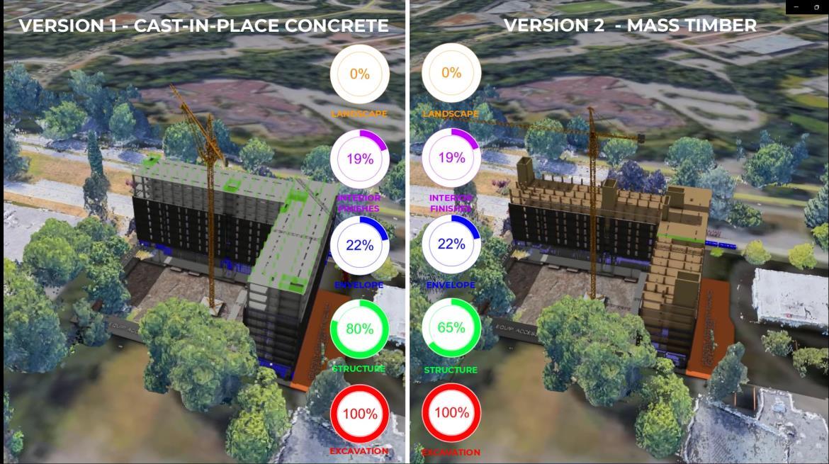
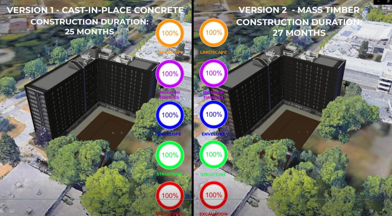
The difference is mainly focussed on scheduling and in terms of budget the Cast in place has a reduced cost, that allows construction process to have additional equipment. For instance, the Version 1 Cast in place overall construction includes an additional mobile crane on its exterior side. This comparison also helps us to outline the differences. The concrete erection goes floor by floor, while the mass timber erection has CLT Cores that are erected three storeys at a time. The overall time difference is the time frame where the construction duration of the concrete construction is 25 months, while the mass timber construction is 27 months as Figure 2 shows.
Figure 1 Overall 4D construction comparison during construction
As the previous two methods have been compared with this 4D simulation, the third unusual methodology can get started as part of this comparison as well. The super frame structure is first to be confirmed and consulted with a steel work company. During it’s the concept design, scheduling is substantial as it drives several parameters on how this construction is being carried out.
2.1.Project Schedule
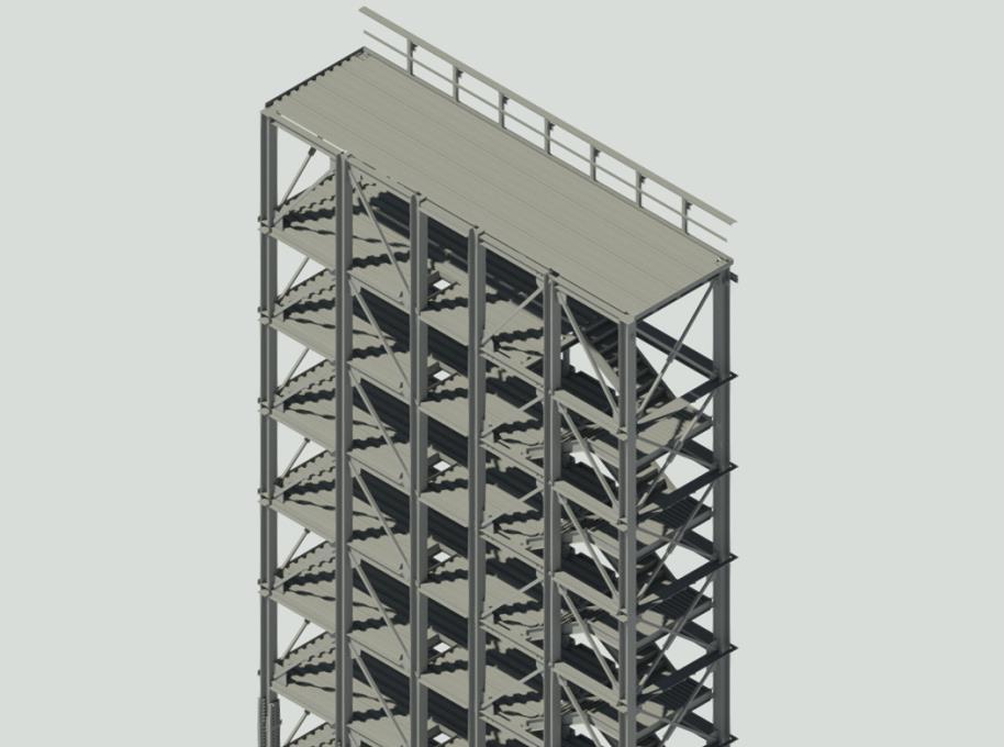
As the building general shape shows, a proper accommodation for the frame structure uses the stair shafts as steel towers and a core structure. These towers can be identified inside the building as follows.
Figure 2. Overall 4D finished construction process
Each of these towers is composed by the mostly by the same elements, meaning same number of braces, stairs, floor decks and major columns assemblies. The initial grouping of elements was analyzed and determined by the way it can be welded together and then stacked as prefabricated modules efficiently.
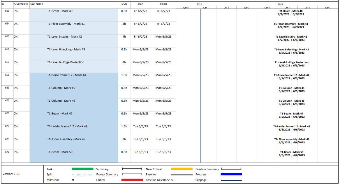
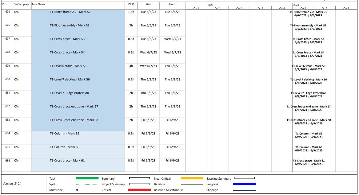
The schedule can be summarized as follows according to Table 1, for the construction timing of a single steel tower.
ESTIMATED TIME
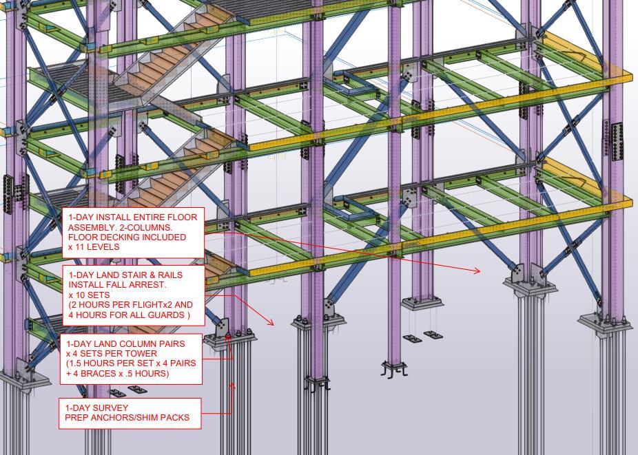
ERECTION SCHEDULE
1 DAYS SURVEY SET SHIM PACKS LAYOUT
4 DAYS LAND MAJOR COLUMN ASSEMBLIES
4 DAYS LAND LOOSE BRACES
11 DAYS LAND FLOOR PLATFORMS AND DECK
10 DAYS LAND STAIRS/ GUARDS
4 DAYS TRUE/ PLUMB/ ALLOWANCE/ INSPECTIONS AND DEFICIENCIES
34 DAYS TOTAL PER TOWER (7 WEEK AVERAGE)
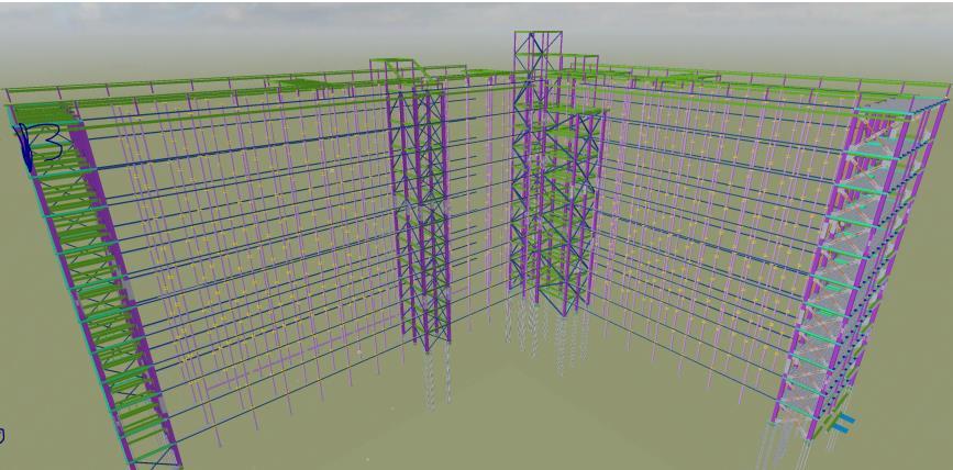
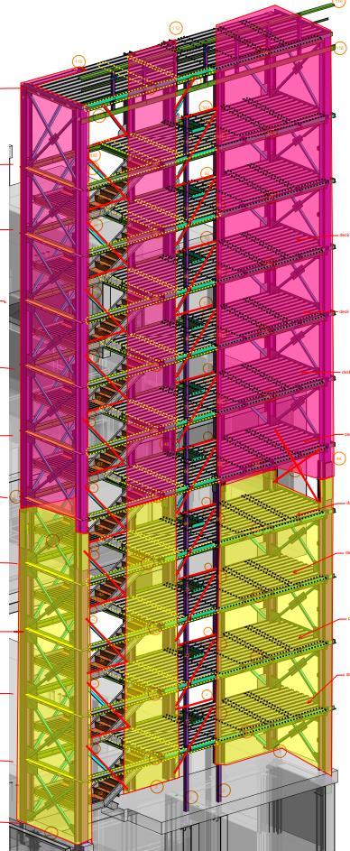
Figure 3. Super frame structure for the entire building
Table 1. Summary of the Current Construction phases
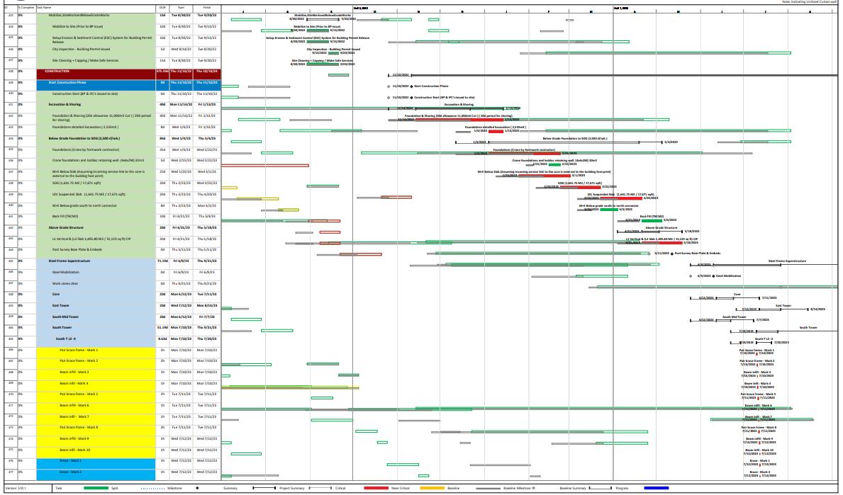
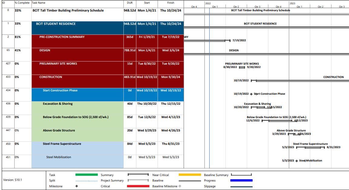
As figure 2 shows, the main frame structure is composed by 4 steel towers and a core structure. Since, the overall frame structure accounts with 4 towers, the calculated week average time should be multiple by 4. However, due to costs availability in regards the prefabricated budget, 2 towers can be erected in tandem, meaning almost simultaneously. This would reduce the overall erection time of about 14 weeks total for the 4 towers Additional 10 days are added for addressing any welding work. In Appendix B, it can be found a much-detailed schedule, developed in Microsoft Project Software.
Understanding the current construction projection is substantial in order to target any time efficiency problem and be able to use new constructions for faster development. Since the assembly time is quite efficient, the current components arrangement has nor been fully explored or subjected to any internal changes. This exploration is what the preassembly proposed method is targeting and is expected to reduce overall construction time and be more on-site efficient.
Figure 4. Steel Construction Task Assignment Close Up
2.2. Proposed Assembly Option
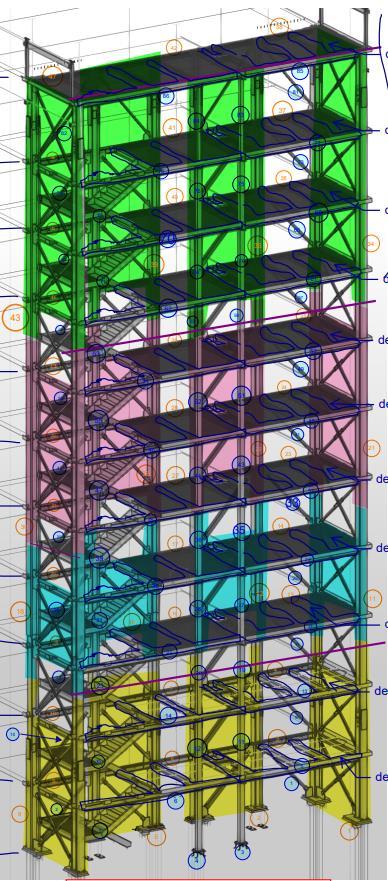
Revising again the latest assembly, the construction was separated by levels which included a separation of around 7 levels per sections, which in the whole tower would be an overall amount of 4 sections, as Figure 5 shows For the new proposed arrangement, the number of portions gets reduced to the amount of 2 overall, separated by around the vertical tower midspan.
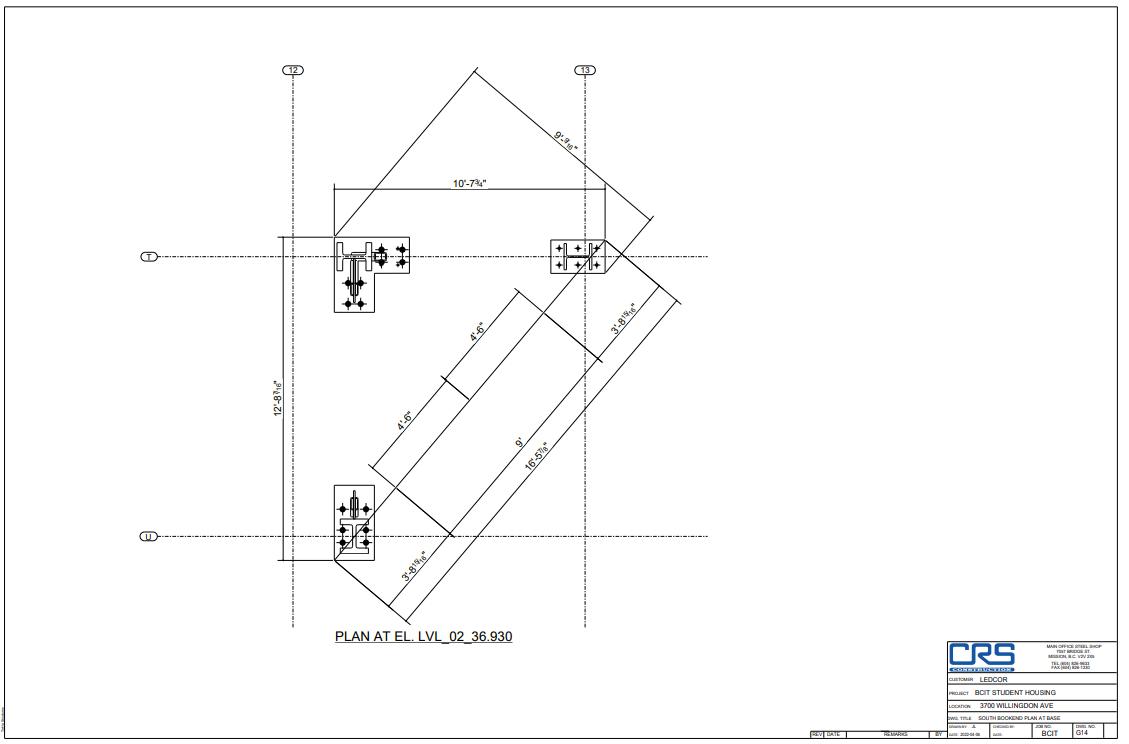
This is possible as at midspan, the connection between Level 6 and Level 7 contains the main bolt assembly and steel plate to column connection in the entire assembly. Taking Figure 5 as reference, in plan view in each of these portions from Figure 3, would represent both corners
Figure 5 Overall steel tower assembly decomposition comparison
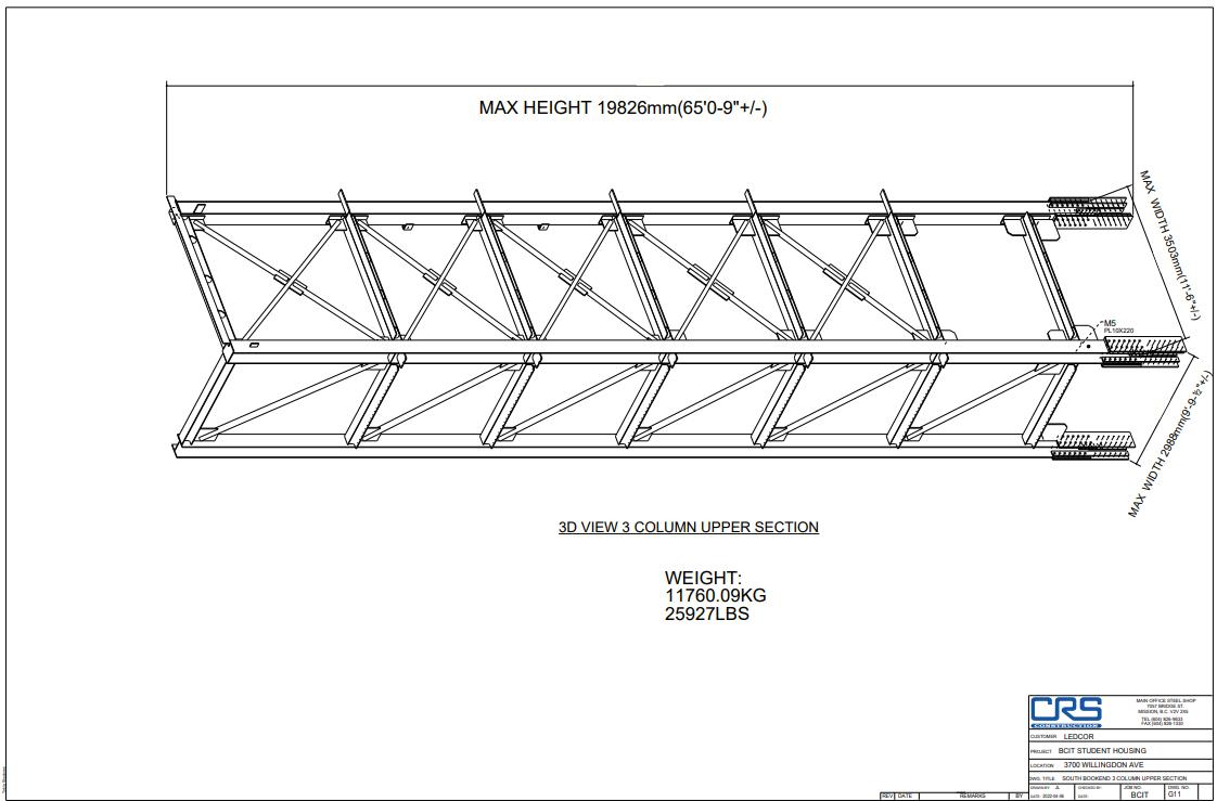
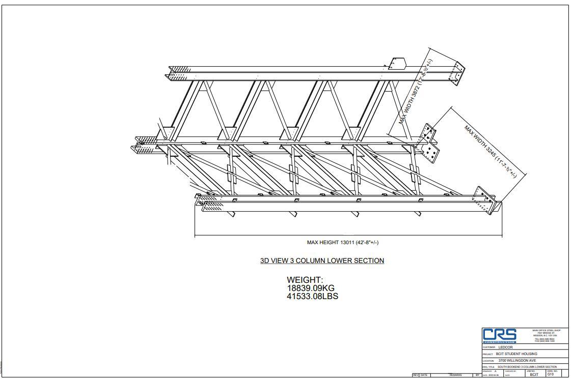
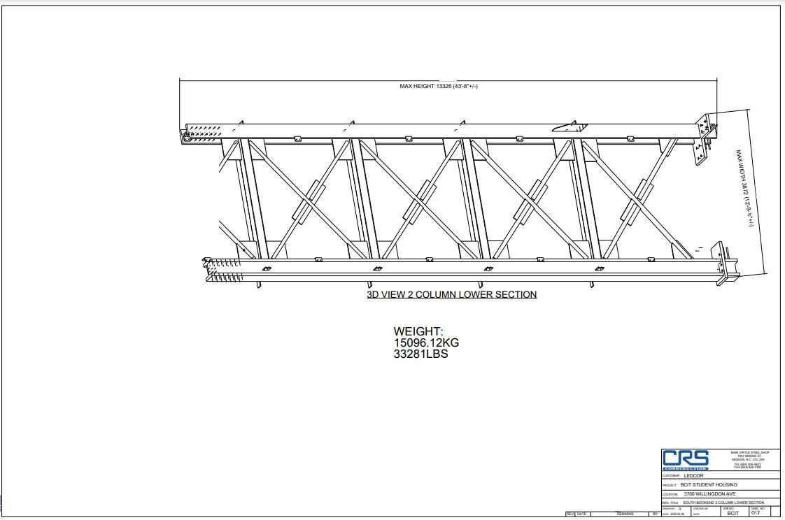
and a side part of the tower, meaning, the total amount of three subcomponents. These three components are key for the assembly process as they include the beam connections between vertical members, braces and columns, elements that were included separately in the previous assembly design As the prefabricated assembly must ensure to not have a weight of over 39, 000 pounds, so the crane can lift it normally, the weight of each of these components were recorded as follows.
As Table 2 showed,the overall prefabricated components arein the weight allowablerange that a regular crane can lift. These new sections are also present in Appendix A, with their respective weights and configuration.
Table 2. New portions overall weight in shop
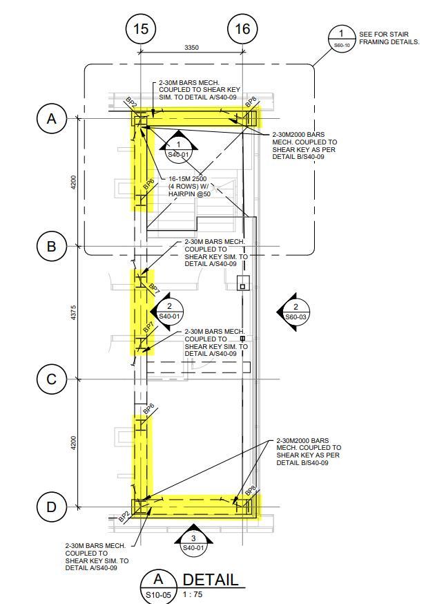
Figure 6. New proposed portion’s location in plan view produced by others
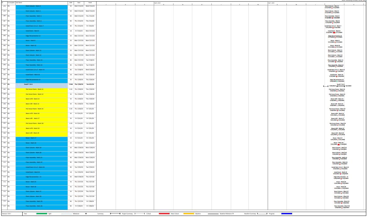
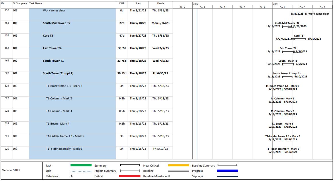
Now, with this new configuration the schedule is also modified as their main components come with a lot of parts assembled prior tower installation. According to the site trades, and the estimating team collaboration, the estimated time of installation for these frames is around 2 – 3 hours. The new version full schedule can also be found in Appendix C. Some value differences change other required assembly process that the previous design had. For instance, the original schedule showed the deck installation as a 1-day process. As several of the pieces are included in these components, already welded and assembled, it is normal that in the updated schedule this process is may faster, For the deck installation, the contour support beams for the landings and connexion to the deck and adjacent frame come already installed, which saves installation time to an overall of 0.5h as shown in Appendix B A similar case can be observed for the stairs installation where the current plan shows a time between 4 hours and 1 complete workday, the proposed plan includes a reduced and constant time of 4 hours for the stair’s installation throughout the building.
Additionally, comparing both full project schedules, it can be noted that the number of tasks barely changes compared to the proposed plan. As mentioned before, the number of single elements inside each portion is the same regardless their arrangement, so many tasks stay unchanged and their mark labels are the only ones that changes, since they direct the overall installation order.Finally, Table 3 summarizes theproposed newschedulein themainconstruction phases for a singular steel tower.
Table 3. Proposed Schedule Summary for new Assembly arrangement
ESTIMATED TIME ERECTION SCHEDULE
1 DAYS SURVEY SET SHIM PACKS LAYOUT
3 DAYS LAND MAJOR COLUMN ASSEMBLIES
5 DAYS LAND LOOSE BRACES
9 DAYS LAND FLOOR PLATFORMS AND DECK
8 DAYS LAND STAIRS/ GUARDS
4 DAYS TRUE/ PLUMB/ ALLOWANCE/ INSPECTIONS AND DEFICIENCIES
30 DAYS TOTAL PER TOWER (6 WEEK AVERAGE)
3. 4D Simulation Result
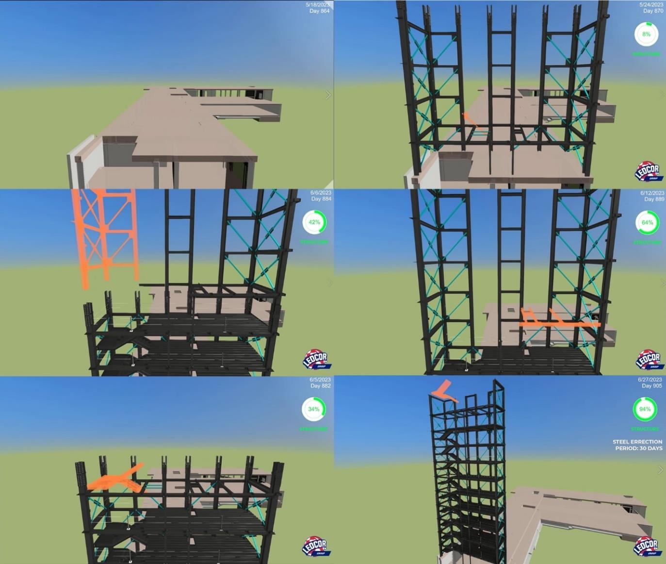
After fully defining the new schedule for this new proposal, a 4D simulation can be performed and can be seen as an the most optimal visualization tool for showing this project. As many pieces get unstilled at the same time, the camera positioning and progress tracking is essential in order to have a proper progress follow-up. The 4D simulation for this project was a video that is broken apart by their main video frames, which is what can be seen in Figure 7.
As mentioned before, the result simulation is found in Figure 7, and it encapsulates how in the first two frames and three main lower parts are placed. Following to this, the inner elements are assembled, including beams, braces, floor assemblies and decking until Level 6. In the second row of frames, the upper sections are also placed and experience the same inner process. In the last frames reflects more about the final elements and roof components that will finish the whole steel structure.
Figure 7 Video frames of the Final 4D simulation product of the new proposed assembly.
The following step after these simulations is to present it to 3 main different teams inside the project, the estimating team, the site logistics coordination and the project Superintendents, or Onsite Supervisors This resource is critical as it clearly shows the assembly process and teams involved can note any deficiency or constraints for their later troubleshooting. After Quality Assurance process as been taken on this process, the following steps mainly rely on site coordination and the prefabrication supplier, so the assembly’s transportation and set up can work efficiently during construction.
4. Conclusions & Recommendations
As the main simulation shows, the overall average construction time for the tower using a lower and upper portion arrangement gets slightly reduced by around 4 days. Since this process can be reproduced in tandem for the other 4 towers, the overall super structure time would be of around 12 weeks, and an additional 10 days for targeting any steel and welding work required In terms of time efficiency, the presented methods are a strong recommendation for a proper construction workflow. It is highly recommended to analyze the same process and see if it compromises the entire structural integrity, building budget, material availability and construction equipment on site.
References
Mani Golparvar-Fard, F. P.-M. (2009). Visualization of Construction Progress Monitoring with 4D Simulation Model Overlaid on Time-Lapsed Photographs. Journal of Computing in Civil Engineering, 23(6).
Michel Guévremont, A. H. (2020). Review and Survey of 4D Simulation Applications in Forensic Investigation of Delay Claims in Construction Projects. Journal of Legal Affairs and Dispute Resolution in Engineering and Construction, 12(3).
Ng, V. W. (2006). Towards adoption of prefabrication in construction. Building and .