
cegageos.ca THE MAGAZINE OF CANADIAN ENERGY GEOSCIENTISTS MAY/JUN 2024 • ISSUE 3 • VOL 51 Reservoir


All of your CCS reservoir solutions, stored in one place!
Enhanced Oil Recovery
• PVT Testing
• Core Flooding Experiments
Storage Capacity
• In Situ Petrophysical Properties
• Fluid Saturations
• Pore Volume Compressibility
• CO2 Dissolution Testing
• Adsorption Isotherms
Cap Rock Integrity
• Permeability & Threshold Pressure
• Mechanical Strength Analysis
• Seal Integrity


Precambrian Stromatolites, Montana.
Stromatolites occur within the 1.45 Ga Mesoproterozoic Belt-Purcell Supergroup, Glacier National Park, Montana, along the Highline Trail, below Garden Wall and above Going to the Sun Road. These belong to the form-genus Collenia and are hosted in the Helena Formation of the Middle Belt that is correlative with the Siyeh Formation in Alberta and British Columbia. Stromatolites are microbialites - layered biochemical accretionary structures that have grown in shallow water.

Learn new skills and expand your professional network by volunteering with any of CEGA’s programs. Share your experiences through our mentor@CEGA inita�ve.
Advance your technical knowledge through peer reviewed papers in the Bulle�n of Canadian Energy Geoscience and ar�cles in the digital Reservoir magazine.
Further your educa�on and receive CPD credits with our technical offerings - technical luncheons, division talks, short courses, field seminars, and more!
Meet members of the industry through our social events. Several networking events are held throughout the year, as well as our annual spor�ng events - Mixed Golf, Road Race and Squash 150 - 540, 5th Ave SW, Calgary, AB, T2P0M2
Phone : 403-234-5610 | Web : www.cegageos.ca | Email : membership@cegageos.ca
The RESERVOIR is published 6 times per year by the Canadian Energy Geoscience Association. The purpose of the RESERVOIR is to publicize the Association’s many activities and to promote the geosciences. We look for both technical and non-technical material to publish.
The contents of this publication may not be reproduced either in part or in full without the consent of the publisher.
No official endorsement or sponsorship by the CEGA is implied
for any advertisement, insert, or article that appears in the RESERVOIR unless otherwise noted. All submitted materials are reviewed by the editor. We reserve the right to edit all submissions, including letters to the Editor. Submissions must include your name, address, and membership number (if applicable). The material contained in this publication is intended for informational use only.
While reasonable care has been taken, authors and the CEGA make no guarantees that any of the equations, schematics, or
devices discussed will perform as expected or that they will give the desired results. Some information contained herein may be inaccurate or may vary from standard measurements. The CEGA expressly disclaims any and all liability for the acts, omissions, or conduct of any third-party user of information contained in this publication. Under no circumstances shall the CEGA and its officers, directors, employees, and agents be liable for any injury, loss, damage, or expense arising in any manner whatsoever from the acts, omissions, or conduct of any third-party user.

PRESIDENT
Andrew Vogan
ConocoPhillips Canada Ltd. andrew.vogan@cegageos.ca LinkedIn

FINANCE DIRECTOR ELECT
Rachel Lea
Suncor Energy directorfinanceelect@cegageos.ca

DIRECTOR
Scott Leroux
Mancal Energy Inc. education@cegageos.ca Linkedin
CEGA OFFICE
#150, 540 - 5th Ave SW
Calgary, Alberta, Canada T2P 0M2
Tel: 403-264-5610 | cegageos.ca

PAST PRESIDENT
Simon Haynes Haynes Geological Consulting simon.haynes@cegageos.ca

DIRECTOR
Gary Bugden Cabra Consulting Ltd membershipdirector@cegageos.ca Linkedin

DIRECTOR
Michael Livingstone Eathie Consulting Limited technicaldivisions@cegageos.ca LinkedIn

PRESIDENT ELECT
Shelley Leggitt
Kiwetinohk Energy Corp. shelley.leggitt@cegageos.ca

DIRECTOR
Ross Kukulski
Chevron Canada publications@cegageos.ca

DIRECTOR
Michelle Thoms Freehold Royalties Ltd. outreach@cegageos.ca Linkedin
MEMBERSHIP INQUIRIES
Tel: 403-264-5610
Email: membership@cegageos.ca
ADVERTISING INQUIRIES
Britney Tang
Tel: 403-513-1230
Email: britney.tang@cegageos.ca

FINANCE DIRECTOR
Scott Norlin Wood Mackenzie directorfinance@cegageos.ca Linkedin

DIRECTOR
Marcelina Labaj
Central European Petroleum Ltd. fieldtrips@cegageos.ca Linkedin

DIRECTOR
Kevin Webb
Aquitaine Energy Ltd. conferences@cegageos.ca Linkedin
CONFERENCE INQUIRIES
Kristy Casebeer
Tel: 403-513-1234
Email: kristy.casebeer@cegageos.ca
MANAGING DIRECTOR
Emma MacPherson
Tel: 403-513-1235
Email: emma.macpherson@cegageos.ca


When looking for new analogues in sedimentology, most geologists tend to look down rather than up. However, the sky above us provides an enormous sedimentological laboratory, where the world’s largest rivers, such as the Gulf Stream, flow through rippled deposits that may stretch for hundreds of kilometres. Huge plumes of cloud rear up in response to upwelling currents. All of us are familiar with a herringbone sky, but how many have paused to wonder how such structures are formed. By the end of this article, hopefully our readers will realize that every flight is, in reality, an aero-geological field trip.

There are many types of clouds, all made up of millions of tiny droplets of water and ice (unless you are on another planet, of course!). These droplets are so light that they can float on air but are liable to be transported and moulded into structures by air currents. Hence, they provide a unique analogue to the behaviour of sediments, such as sand grains and clay particles, under the influence of submarine and fluvial currents. The stratification of the atmosphere ensures that clouds usually behave as though in contact with an underlying bed surface. Many of the same sedimentary structures that may be observed in ancient and recent deposits are also clearly visible in the sky. There are heavenly analogues to dunes, to ripples of many kinds, and to dewatering structures. There are also aerial channels, incised valleys
Cumulus Low Fluffy with flat bases; may grow vertically; formed by convection, size varies with temperature profile
Cumulonimbus Low More complex structure, often with an anvil top (caused by wind shear), formed by water vapour condensing. Associated with severe weather
Nimbostratus Low to Middle Multilevel, amorphous, uniform dark grey cloud, appears illuminated from within; formed by slowly rising warm air mass (may contain cumulonimbus)
Stratocumulus Low Dark, rounded masses, usually in groups, lines or waves, may cover huge areas; formed by break up of stratus cloud by weak convective currents held down by overlying drier, stable air
• humilis puffy , flattened shapes
• mediocris like humilis but more vertical
• congestus towering, cauliflower-like
• fractus ragged
• calvus similar to congestus
• capillatus with cirrus-like, fibrous top
• flammagenitus rapidly growing clouds formed by fires, volcanic heat
• very thick, opaque and featureless so does not have species – least picturesque
• stratiformis flat, lumpy sheets
• lenticularis flat, elongated, seed shaped clouds
• castellanus puffy, tower-like formations atop the cloud layer
• also undulatus (parallel waves or rolls) parallel to wind shear; radiatus, waves perpendicular to wind shear; duplicatus (multiple layers); mamma (mammatus cloud); asperitas (chaotic, wavy undulations due to severe wind shear)
Stratus Low Horizontally layered or featureless, hazy, with a flat base; formed by weak air currents lifting air from the ground
Altocumulus Middle Globular masses in rolls or layers, formed by convection
Altostratus Middle Grey featureless sheets; formed when large masses of warm, moist air rise causing water vapour to condense on dust particles
Cirrus High Delicate and wispy; composed of ice crystals, formed when warm air rises and vapour deposited on dust particles
Cirrocumulus High Regular, rippled pattern or as rows of clouds, cast no shadow; formed by convection with high altitude instability, short lifespan
• nebulosus featureless veil with no distinctive structure
• fractus irregular shape, fragmented, ragged
• castellanus puffy, tower-like formations atop the cloud layer
• stratiformis (sheets or flat patches)
• lenticularis (“UFOs”)
• castellanus, vertical development
• floccus, tufted
Cirrostratus High Transparent clouds that cover large areas of sky. May be very thin, made of ice crystals; formed due to slower rising air
• castellanus cumiliform tops
• fibratus looks striated, common
• floccus series of tufts
• spissatus dense
• uncinus hooked, mare’s tails (fast wind)
• stratiformis sheet-like
• lenticularis lens shaped, tapering at ends
• castellanus build upward, turreted
• floccus tufted
• others include undulatus, with a wavy, undulating base, associated with stratiformis
• fibratus high fibrous sheet, similar to cirrus but with detached filaments
• nebulosus covers entire sky like a featureless veil
Big sand dunes stacked up during storms
May have ripples on margins
Large sand dunes, high energy deposition = shallow water
Massive sands and thick mudstone beds
Sand sheets (stratiformis)
Rippled deposits (undulatus and radiatus, with the former transforming into the latter with increasing wind speed)
Dewatering structures (mamma)
Hummocky cross-stratification = storm deposits (asperitas)
TABLE 1 Major types of cloud with methods of formation, species of cloud and terrestrial equivalents (some data drawn from Wikipedia). See also Figure 1. Cloud
Massive sands and thick mudstone beds (nebulosus)
Lower plane bed flow (nebulosus)
Sand sheets (stratiformis)
Rippled seabed, may be undulating
Dewatering structures (lenticularis)
Pods of sediment (lenticularis)
Primary current lineations (fibratus)
Starved ripples
Rippled seabed, may be undulating
Thin veneer of sediment on bedrock seabed

Major types of cloud corresponding to altitude (BBC 2000)
infilled with cloud deposits and eroded coastlines. These may appear analogous to terrestrial deposits, but there are also some significant differences:
• The lack of underlying bedrock means that we get to see the underside of these deposits, something that is usually not possible in nature.
• The scale of these features dwarfs their terrestrial counterparts, an excellent example being the Jet Stream which is more than 5000 km long, 20+ kms wide and flows at 50 to 120 km/hour.
• The amount of flow and turbulence is much greater than on the Earth’s surface, with storms provide a counterpart to catastrophic flooding events, giving us the opportunity to see the impact of high currents on a scale rarely possible in the subaqueous realm.
• The impact of gravity on deposition is much less than in the terrestrial realm, meaning that sedimentary structures often have steeper dips.
• The instability of clouds means that any sedimentary structure is, by definition, transient, requiring immediate observation if it is not to be lost forever.
Clouds were originally classified using a Linnean system proposed by Luke Howard in 1802. Clouds are divided into five physical forms which can be further classified into altitude levels to derive ten basic genera. The three principal categories are shown, highlighted in yellow, in Table 1, along with other common cloud types in green. The clouds can be further subdivided into species based on their morphology. The shapes of the clouds are governed by air temperature, the strength of convective currents, humidity, the concentration of particulates in the atmosphere, wind speed and shear and air instability.
The processes that create different types of cloud are generally well understood, meaning that the types of cloud can be predicted in different types of weather systems. As shown in Figure 2, the patterns of convective currents generated by weather systems strongly influence the cloud types in different parts of a warm front, with stratus family clouds at lower altitudes and cirrus family clouds at higher altitudes.

Cloud types associated with a warm front (Kelvinsong, Wikipedia)
Folk (1976) examined flow behaviour in a variety of media from subaerial and subaqueous sediment to clouds made up of water droplets. He described lower flow regimes producing transverse ripples, crossbeds and dunes. Under high shear, upper plane bed flow, laminated plane beds with longitudinal sediments streaks (upper plane bed laminations) are deposited. Small changes in grain size (water droplet size) and viscosity (related directly to temperature) can lead to a change in circulation from lower to upper flow without changes in flow velocity.
Increasing shear is thought to lead to a transition from transverse rollers (perpendicular to current or wind direction), through a festoon stage and into longitudinal vortices (current or wind parallel). The festoons represent undulations along the transverse ripple crests as the increasing currents begin to push sediment downwind. Further increases in current speed will lead to a chaotic turbulence, eventually stabilizing into the next order transverse ripple phase. The zones of chaos may develop antidunes, their size depending on wind (current flow) speed.
Folk postulated three orders of magnitude, separated by zones of chaos at the transitions. Each order is five to ten times the amplitude (or relief) of the previous order, so as wind speed increases (usually with altitude), we will see a change in the size of the airborne sedimentary structures. As in terrestrial deposits, there may also be smaller structures, such as ripples, on the surface of larger, dune features. Generally larger droplets or ice crystals form larger, taller sedimentary structures, ranging from ripples to dunes to cumulus in clouds.
As a general rule, the most common clouds occur at low altitudes, with frequent convection and mixing. Conditions are very moist with nimbostratus producing precipitation. There may be ground interference especially where mountains “poke up” into the atmosphere. Clouds with vertical development, such as those in the cumulus family, require strong updraughts of warm moist air, often develop in zones of deep instability and may be vertically zoned. In these conditions it is normally cumulonimbus that produces precipitation.

Graph of stream power against grain size to show the resulting sedimentary structures (after Myrow and Southard 1991)
This article is not meant to be an exhaustive catalogue of flow behaviour and resulting aerial bedforms for every category of cloud (watch this space for a forthcoming paper that tries to do just that). Rather it aims to marry the better known, terrestrial bedforms and sedimentary structures with their equivalent cloud types. In terrestrial settings, stream power (flow rate and volume) and grain size help to determine the type and size of sedimentary structures that are preserved (Figure 3). By comparing these land based sedimentary structures to the structures seen in clouds, this can give an idea of wind speed and droplet size.
Ripples are regularly spaced undulations on a surface. There is a threshold wavelength (50 cm on Earth) above which they are classified as dunes. They show a wide variety of shapes and may exhibit cross-lamination internally. Asymmetric ripples indicate unidirectional flow while symmetrical ripples form in response to wave action although things are somewhat more complex than this in nature. Ripple crests may also be straight or curved, with curved crests more common in asymmetric ripples. Ripples in terrestrial settings typify lower flow rates (see Figure 3).
The most common cloud type to exhibit ripples is Altocumulus. There is little vertical development and they occur at mid-level altitudes, with steady winds with slight instability. The basal surface of the rippled interval often undulates laterally. Cirrocumulus clouds behave in a similar way. The undulating, rippled patter, made up of rows of small clouds, is similar in appearance to fish scales and is termed a mackerel sky.
Stratocumulus clouds may form flow parallel ripples in undulatus, transforming to flow perpendicular ripples termed radiatus with higher wind speeds. More complex patterns are generated by interference between wind currents with different orientations, much like interference ripples in terrestrial settings.


Interference ripples in Stratocumulus from the Atlantic


Stratocumulus with striking ripples in the


Dunes and sandwaves are larger than current ripples although many features of their shape and organization are similar. Complete dunes preserved in the fossil record are rare, so much of the interpretation is based on their internal cross-beds. This is partly because of later erosion of much of the upper portions of dunes during the deposition of subsequent, overlying dunes.
The sky is a very dynamic place, with few structures surviving more than a few minutes. However, during the brief life of these structures, it is possible to see complete features including dunes. Internal cross-beds are occasionally visible in clouds, but generally cannot be discerned even as an aeroplane descends through the cloud mass. The constantly mobile water droplets within a cloud do not lend themselves to preserving the internal bounding surfaces. Large bar forms are common in Stratocumulus and may have “feathered”, rippled margins.


The amount of convection in the sky, married to the relative buoyancy of the water droplets compared to coarser sand grains, means that cloud banks of “sediment” i.e. water droplets, can build up for hundreds of metres. Cumulus congestus appear as towering, cauliflower-like structures up to a kilometre or more in thickness. The closest terrestrial analogue is large dunes formed during rapid deposition of sediment during storms or by strong tidal currents. However, the scale is usually significantly smaller in terrestrial deposits. Few classic convective currents seen in terrestrial deposition. The only example is in deserts, where air is sucked in from all sides over star or oghurd dunes.


HCS is a form of cross-bedding usually formed by the action of large storms, taking the form of scoured bases overlain by a characteristic hummocky zone with several second-order truncation surfaces separating individual undulating lamina sets (Harms et al 1975). It is generally found in the lower shoreface and takes on the forms of hummocks and swales, elliptical and one a scale of metres. It is thought to form under a combination of unidirectional and oscillatory flow generated by relatively large storm waves in the ocean.
Asperitas is a cloud formation first proposed by Gavin Pretor-Pinney of the Cloud Appreciation Society in 2009. It is similar to undulatus clouds and occurs as a species in Altocumulus or Stratocumulus. They are defined as wave-like structures, more chaotic and with less horizontal organization than the variety undulatus. These cloud structures bear a striking similarity to HCS and may be generated by a similar interaction of variable flow in multiple directions.
Higher currents tend to transport most of the sediment and deposition is limited to PCLs – streaks of sediment running parallel to the flow direction. The same is true at high altitudes where the wind sppeds are much faster. This leads to the deposition of thin streaks of cloud, as well as mare’s tails, which are streaks of wispy cirrus uncinus clouds forming high in the atmosphere. Strong winds, often made up of warmer air, blow these cirrus clouds and cause them to curl with the moving air. It’s this warmer wind that usually brings rain to the forecast.


asperitas, chaotic wavy undulation due to severe wind shear, Calgary AB
Hummocky cross-stratification and Stratocumulus asperitas


Stratocumulus mammatus formed in the same way as dewatering (foundering) in sediments (Photo sourced online)

Erosive feature in cloud surface


Some other cloud related features
There are many extraordinary features associated with clouds, too many to detail in this short article. We have seen some of the common sedimentary structures observed in the sky; others include lenticularis clouds, often looking like UFOs in the sky. They are formed when stable moist air flows over a mountain, creating standing waves downwind. Temperatures at the wave crests may drop, forming the lenticular clouds. Another type of cloud akin to terrestrial deposits are mammatus clouds. They form in association with large Cumulonimbus clouds, where turbulence leads to sagging of moist clouds creating breast-like features, hence the name.
A roll cloud (volutus) is a low, horizontal, tube-shaped, and relatively rare type of arcus cloud. They differ from shelf clouds by being completely detached from other cloud features. They are a solitary wave called a soliton and the rolling is caused by variation in speed and direction of the winds with altitude. One of the most famous occurrences in the Morning Glory cloud in Queensland, Australia.
One fun suggestion related to vapour trails, or contrails, left by planes as they cross the skies. After considering them as possible structural features, my correspondent postulated that they could be thought of as unusually long and straight burrows. A new field of aero-ichnology is born!
Erosional and structural features can be observed in clouds. Sometimes the wind will blow strongly along the margin of a cloud bank, leaving a sharp edge. Erosive features can also be observed incising in the upper surface of Stratocumulus clouds, possibly due to localized wind currents stripping away water droplets. Mountains can poke up into the atmosphere and cause eddies due to interference with cloud movement driven by wind currents. These wind currents are driven, for the most part, by the rotation of the Earth.
This article has only scratched the surface of cloud sedimentology. The classification of clouds is challenging, as the boundaries between types of cloud are fluid and ever changing. The study of clouds has the potential to elucidate the formation of sedimentary structures at an extraordinarily compressed timescale; the behaviour of very light particles; and the development of sedimentary structures on a very large scale. Analogues to virtually every class of sedimentary structure are floating above our heads and can be studied from every angle, either standing outside or from the window of a plane. I hope that each one of you readers takes the chance to look up rather than down as a result of this article.
Cloud Appreciation Society: https://cloudappreciationsociety.org/ https://earthsky.org/
Folk, R.L. 1976. Rollers and ripples in sand, streams and sky: rhythmic alteration of transverse and longitudinal vortices in three orders. Sedimentology 23 pages 649 to 669
Harms, J.C., Southard, J.B., Spearing, D.R. and Walker, R.G. 1975. Depositional environments as interpreted form primary sedimentary structures and stratification sequences. S.E.P.M., Tulsa Short Course no. 2, 161 pp.
Met Office:https://www.metoffice.gov.uk/weather/learn-about/weather/ types-of-weather/clouds
Myrow, P.M. and Southard, J.B. 1991. Combined-flow model for vertical stratification sequences in shallow marine storm-deposited beds. J. Sediment. Res., 61, 202–210.
Wikipedia: multiple pages


MAY
May 2nd Online + In Person
Thursday | 12:00 - 1:00pm MST
Energy Transition and Sustainability Technical Division
The Sedimentology of High Perm Streaks and Reservoir Heterogeneity: Implications for CCS
Speaker: Jon Noad
Location: A unique zoom link will be sent to your primary email prior to the event OR CEGA Conference Room, +15 level, 540-5 Ave SW, Calgary AB
May 7th Online Only
Tuesday 12:00-1:00 pm MST
Geothermal Technical Division
Constructing a Geothermal Test Facility to Demonstrate and Scale Geothermal Technologies
Speaker: Robert Klenner
May 15th Online + In Person
Wednesday | 12:00 - 1:00pm MST
Heavy Oil/Oil Sands Technical Division
Strat-Log High-Density Reservoir Monitoring
Speaker: Lars Hinrichs and Pavan Elapavuluri
Location: A unique zoom link will be sent to your primary email prior to the event OR CEGA Conference Room, +15 level, 540-5 Ave SW, Calgary AB
May 16th Online + In Person
Wednesday 12:00 pm -1:00 pm MST
GeoWomen Talk
How to Ace Public Speaking in the Workplace
Speaker: Michelle Lund
Location: A unique zoom link will be sent to your primary email prior to the event OR 540-5 Ave SW, +15 Level Calgary, AB T2P 0M2
May 22nd Online + In Person
Wednesday | 12:00 - 1:00pm MST
Structural Technical Division
Characterization of Natural Fractures of the Upper Devonian Duvernay Formation in the Kaybob Area, Alberta
Speaker: Guido Garcia Rodriguez
Location: A unique zoom link will be sent to your primary email prior to the event OR CEGA Conference Room, +15 level, 540-5 Ave SW, Calgary AB
May 29th
Wednesday | 12:00 - 1:00pm MST
International Technical Division
The Orange Basin, Deepwater Namibia –One of the World’s Newest and Hottest Oil and Gas Hunting Grounds
Speaker: Tako Koning
Location: CEGA Conference Room, +15 level, 540-5 Ave SW, Calgary AB

May 8th
Wednesday | 11:30 am -1:00 pm MST
Renewables, Storage and EV’s impact on Global Oil and Gas Demand
Speaker: Tim Polega, Drax Group
Location: Calgary Petroleum Club, Devonian Room 319 5 Ave SW, Calgary, AB T2P 0L5
June 19th
Wednesday | 11:30 am -1:00 pm MST
Society needs Geoscience. Now, more than ever - June GeoConvention Luncheon
Speaker: Dr. Ellie MacInnes
Location: Hyatt Regency Calgary, Imperial Ballroom 4/6/8 700 Centre Street SE, Calgary, AB T2G 5P6


We are once again excited to announce the CEGA Core Conference. Hosted at the Core Research Centre in Calgary from June 20-21, 2024, this year’s conference is entitled Fueling the Future: Core Insights for Energy Resource Exploration and Development. Over the course of two days, we will have presenters explore a wide range of exciting topics and showcase cores from across Canada. Siliciclastic and carbonate focused sessions will look at geochemical data, as well as microscopic-scale up to regional-scale depositional features. These two sessions will include Silurian aged core from the Permian Basin, shallow marine carbonates from off-shore Newfoundland, and Montney and Duvernay cores from central Alberta. We are also excited for our mini sessions on the Basal Cambrian and on CO2 Storage. The Basal Cambrian session will discuss pore space, fluid dynamics and regional depositional frameworks for the Basal Cambrian in both Alberta and Ontario. The CO2 Storage session will examine CO2 and helium storage in sandstone, carbonate and evaporite intervals. The Core Conference will be rounded out by an Applied Geoscience session that will integrate detailed core analysis and regional depositional frameworks key in understanding oil and gas production. This session includes presentations on open hole multileg drilling within the Frobisher beds of SE Saskatchewan, key drivers of oil sands quality and development, and the fracability within the Cardium.
The 21 presentations represent the range of focus that geoscientists are undertaking to fuel society's future. The presenters represent the forefront of industry, government, and academic research, and we are thrilled that they will be able to share their expertise with us during this year's Core Conference.
Session Chairs:
Mastaneh Liseroudi, GSC, Rob Paul
This first session looks at mitigating CO2 emissions by sequestration of CO2 in the Basal Cambrian Sandstone, as well as in carbonates and halite. The session starts by looking at the Basal Cambrian Sands of the WCSB and Southwestern Ontario, followed by the Leduc formation near the proposed CO2 storage site in the Simonette area. The session concludes with a look at salts and non-salts within the Elk Point Group.
Session Chairs: Celine Chow, Saturn Oil + Gas Inc., Ozzy Ofoegbu, Cenovus
This session highlights various carbonate reservoirs, from Southeast Saskatchewan and Southern Alberta to offshore Newfoundland and the United States. Interpreting well log data for facies modeling will be explored, along with the use of pXRF chemostratigraphic data. Gaining understanding of the impact of sea level fluctuation on carbonate sequence stratigraphy and the timing of diagenetic processes in carbonate reservoirs is of the utmost importance as we strive to identify new plays and enhance our development strategies.
Session Chairs:
Lauren Eggie, Imperial Oil, Daniela Becerra, SLB
The fundamental component to success for any resource play is an in-depth understanding of the subsurface. This session is focused on integrated reservoir characterization through core descriptions, well log analysis, and mapping methods utilized in a wide range of conventional and unconventional plays. These plays include the Cardium in the Pembina field, the Mississippian Frobisher State A Marker in the Williston Basin, and two stratigraphic units of the Kearl oil sands mine, namely the Clearwater Formation and the Quaternary succession. There is discussion on the impact of core extraction techniques for optimizing reservoir quality and rock properties for both conventional and unconventional plays. The topics covered in this session offer valuable insights that can be utilized to delineate reservoirs, optimize development strategies, and identify potential geotechnical hazards more effectively.
Session Chairs:
James Burr, Spur Petroleum, Cole Ross, Spur Petroleum
When evaluating siliciclastic reservoirs, understanding the internal stratigraphic architecture is a foundational step in reservoir characterization whereby the study of core is paramount. This session will explore a deeper look into the sedimentologic and stratigraphic nuances within the Mannville Group, in addition to the Montney and Duvernay Formations.


The Petrophysics and larger Geoscience and Petroleum Engineering community lost a true giant in the field on Mar 21, 2024. After graduating from McGill in 1962 Ross headed west to begin his 60+ year career focused on the science and application of Petrophysics. After working with Schlumberger, Pan-Arctic, Sproule and others he built up his own company utilizing ground-breaking microcomputer-based techniques to advance the field of well log analysis and reservoir evaluation.
Ross’s legacy will remain strong within the more than 3000 students he taught and with the incredible website that he developed throughout his career. Ross was recognized in 2019 for his tremendous contributions with the Canadian Well Logging Society (CWLS) Lifetime Achievement Award.
Ross’s other passions included his Hereford Ranch in west-central Alberta and his impressive train collection and set-up at that same location.
Ross Crain was a true ‘icon’ in the Petrophysics community and he will be sorely missed.
By Reigh MacPherson

The Medal of Merit has been awarded since 1952 and is the most prestigious and oldest technical award of the society. The medal is awarded annually for the best peer reviewed paper on a geological subject related to the petroleum geology or the geology of energy generation and extraction, of Canada. The stated objectives of the Medal of Merit Award are: to promote the preparation and publication of geological papers of high quality, to give honorable recognition to works of merit, and by means of suitable publicity, to bring the attention of the members and of the public to the activities of the geological petroleum profession by awarding the Medal of Merit annually for the best paper.

Michelle Johnston earned her B.S. in Biology with a minor in Environmental Science from Bellarmine University in 2011, and her M.Sc. in Geological Sciences with a focus in coal/ organic petrology from the University of Kentucky in 2013. While in Graduate School, she was an Antoniette Lierman Medlin Award recipient in 2012 from the Geological Society of America Coal Geology Division for her work in petrographic assessments of Eastern Kentucky coals. During this time, Michelle was also a visiting organic petrography student at the University of Witwatersrand in Johannesburg, South Africa, assisting with organic matter characterization for efficient coal utilization in association with Dr. Nikki Wagner. Immediately following graduation, Michelle worked as an organic petrographer for the Center of

Shaina Kelly is an Assistant Professor of Earth and Environmental Engineering at Columbia University in the City of New York and the Assistant Director of Columbia’s Lenfest Center for Sustainable Energy. Shaina and her research group investigate and optimize the interplay between multiphase fluid flow and fluid-mineral interactions in geologic and engineered porous media for sustainable energy applications. Shaina joined Columbia in July 2022. Prior to her academic appointment, Shaina’s 6 years
Applied Energy Research, as well as co-project contributor and organic petrographer for Morehead State University’s EPSCoR-funded project examining microbial diversity in Cenozoic lignite coals for the Department of Physics, Earth Science and Space Systems Engineering. She joined ConocoPhillips, LTD. in 2014 as a geologist working as an organic petrography specialist conducting organic matter characterization, thermal maturity analyses, and organic petrographygeochemistry integration for unconventional source systems for seven years and is now a coal geologist at the U.S. Department of Interior Geological Survey within the Central Energy Resources Science Center, Energy Resources Program (ERP).
of industry experience include roles as Senior Petrophysicist at ConocoPhillips Company and Senior Geoscience Engineer at AquaNRG Consulting Inc. working on related petrophysics and flow in subsurface porous media research topics. Shaina received a PhD in Petroleum and Geosystems Engineering from The University of Texas at Austin in 2015, and a BSc in Environmental Engineering from the University of Florida in 2011.

Dallin grew up in southern Alberta admiring the mountains and developing a love for the outdoors, which eventually blossomed into an interest in geology. He earned his bachelor’s degree in Geology at Brigham Young University, where he co-authored a successful book about the Geology of Utah’s National Parks. Following his time in Utah, Dallin completed a Ph.D. at the University of Calgary, specializing in fine-grained sedimentary rocks. Following his education, he started working at ConocoPhillips where he has worked on a
variety of unconventional reservoirs, including the Eagle Ford, Niobrara, Canol, Duvernay, and Montney. Recently he moved to a new role working in the oilsands to gain additional experience. In his spare time, Dallin volunteers with a group of geoscientists from NASA, academia, and the oil industry to create original geological research and educational materials using satellite data. This has yielded fun opportunities to study everything from shoreline stability to planetary geology.

Eric has a BS from Indiana University and MSc from University of Oklahoma. He is a subject matter expert in the application of petroleum geochemistry and basin modelling for basin and field scale problems. Eric has 32+ years of operator industry experience (ConocoPhillips, USGS, Mobil) in conventional and unconventional (e.g., heavy oil, CBM, tight oil/gas) reservoirs performing subsurface
risk and resource assessment for in-place volumes, hydrocarbon phase prediction and field development and optimization. He has coauthored 45+ publications and patents in using geochemistry and basin modeling for petroleum system analysis. Eric joined APT Houston in 2022 as Chief Geochemical Advisor for Americas.

Rick Tobin is currently the owner of Tobin Reservoir Petrography LLC in Houston, Texas. Rick has over 40 years experience in the oil and gas industry, having worked as a technical specialist on projects involving clastic diagenesis and reservoir quality modeling for Amoco, BP, Maersk Oil, and ConocoPhillips. During his career, Rick has been involved with a number of major projects in the North Sea, onshore basins in Canada and the USA, Gulf of Mexico, offshore Angola, Trinidad, and various
basins in South America, Russia, China, the middle east, northern Africa, and southeast Asia. His technical specialties and research interests include sedimentology, sedimentary petrography (both conventional sandstones and unconventional mudrocks), fluid inclusion microthermometry, diagenesis, and predictive reservoir quality modeling. He received his B.S. from James Madison University in 1977 and both M.S. and Ph.D. degrees from the University of Cincinnati (1979, 1982).

Graduated in 2003 from the University of Calgary with a B.Sc. in geology. The next 5 years were spent in the exploration group for Burlington Resources working western Canada assets. The sale to ConocoPhillips led to a year in the technology group in Houston learning basin modelling with projects in Algeria, Peru, and Norway. Following this; a move to the Norwegian business unit allowed continued growth in basin modelling with projects in the Norwegian Barents Sea, North Sea, and
Greenland. Back in Canada in 2015 saw a quick transition to unconventionals, beginning with basin modelling of the Montney across Alberta and British Columbia and quickly picking up geochemistry, including regional characterization and production allocation. After almost 10 years working the Montney; insights continue to be made on the origin and history of the formation, specifically focusing on the Blueberry Area.
The Redwater Leduc field, discovered by Imperial Oil in 1948, stands as a cornerstone of the Canadian oil industry. This paper summarizes the reservoir’s geological attributes, historical production, and recent endeavors in carbon capture and enhanced oil recovery (EOR). Through a rigorous analysis of reservoir data, historical original oil in place (OOIP) calculations, and the outcomes of a CO2 injection pilot, Conifer illuminates the reservoir’s intrinsic value for hydrocarbon extraction and carbon sequestration.
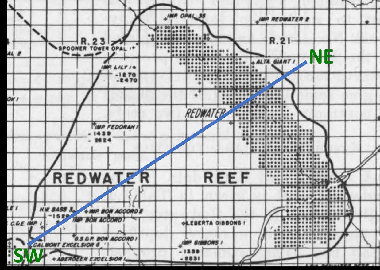
The discovery of the Redwater Leduc field marked a significant milestone in Canadian oil exploration. In 1947, after numerous dry holes, Imperial Oil made the decision to drill below Top Mississippian and hit a major oil find in a Devonian reef at the now-famous Leduc field. A year later, the company made another world-class light oil discovery in the same formation, near the hamlet of Redwater. By the end of 1951, a staggering 971 Redwater wells were drilled, and this field stands today as the third largest oil pool in Canada (Figure 1).1 These early successes at Leduc and Redwater led to a frenzy of exploration and ushered in an era in which Alberta became a major North American oil-and-gas provider. In 1967, Willmon assessed the Redwater Leduc OOIP at 1.28 billion barrels of oil (BBO), and this is the most recent volumetric assessment found by the authors.2 The field has produced over 850 million barrels of oil (MBO) to date, which would suggest a recovery factor (RF) of 69%. This RF is high compared to other conventional oil fields, especially because it has been under primary production only. A few factors likely contribute to this, such as the high-quality reservoir and a very active water drive due to a strong connection to the Cooking Lake aquifer. Conifer Energy updated the volumetrics in 2023 to evaluate the field for an enhanced oil recovery-carbon storage (EOR-CCS) project. A 3D geomodel was built for this assessment and to enable simulation studies.
The Redwater Leduc is a large, isolated reef atoll complex that formed during the Middle Devonian on a broad, gentle high on the top of the underlying Cooking Lake platform. It is 275 m thick, spans over six townships (Townships 56-20W4 to 58-22W4) and is composed of limestone. The strata now dip to the SW due to the formation of the Alberta foreland basin beginning in the Jurassic, followed by erosion of the shallow section to the NE.
The overlying Ireton and coeval Duvernay shales vertically and laterally seal up to 70 m of oil at the reef’s updip NE edge. The quality of these seals is further confirmed by the differing hydrogeological properties of the overlying strata. Below the Leduc, the Cooking Lake platform is generally tight, except at the western limit of the Leduc reef, where it has been altered to a higher-porosity dolomite, allowing fluid communication between the two formations (Figure 2).
The Leduc Formation formed as a stacked succession of backstepping cycles and has been subdivided into the Lower, Middle and Upper Leduc stages. Oil is trapped within the Upper Leduc only (Figure 2). The Redwater reef is characterized by a tidal flat/lagoon central region transitioning outward to reef flat, reef margin, and forereef facies at the reef rim, and current reservoir properties tie closely to depositional facies. The reefal facies are best developed at the windward NE edge. Stromatoporoids were the main reef framework builder, along with minor Amphipora, corals, gastropods and brachiopods.
Willmon’s 1967 OOIP calculations relied purely on core analysis data.2 There is reasonable core analysis data coverage on an areal basis (Figure 3a), but many wells only penetrate the uppermost Leduc, resulting in a downsection decrease in data density (Figure 3b). As a result, there is a data bias towards the youngest subunits. Old neutron-count logs in about 700 wells were not included in this assessment, which is not surprising because these logs are unscaled and difficult to convert into quantitative values (Figure 4).
Willmon developed porosity-water saturation (Sw) transforms, based on analyses of cores subjected to mercury capillary measurements or drilled with oil-based muds. From this

FIGURE 2 Stratigraphic cross-section through the Redwater Leduc reef (updated from Wendte and Callow, 1983). Line of section shown on Figure 1.
analysis, he assumed an average Sw of 25% across the field for volumetric calculations. No net cutoffs were applied. These inputs were used to calculate an OOIP of 1.28 BBO.
For the 2023 assessment, porosity log data were added to the dataset to provide a higherconfidence result. Since 1967, 55 wells have been drilled in scattered locations across Redwater, and some have density, sonic, and/ or scaled neutron-porosity logs. Unscaled neutron-count logs are still the dominant porosity log type, and they were converted to quantitative porosity logs using a multi-step process.
Converting neutron-count logs to scaled porosity logs is time-intensive and must be done on each well individually. First, the log must be normalized using two calibration zones with consistent properties (Figure 5).3
Logs can be converted to porosity using either a shale (A1) or high-porosity zone (A2), and a tight zone (B). The Ireton shale was identified as a potential shale calibration zone, but it is usually behind casing over an openhole Leduc section. The neutron-count logs were run after casing was set, and readings over the cased section were poor. Therefore, in this study, the logs were rescaled using a tight and a porous Leduc interval and converted to
porosity using a semi-log conversion. This analysis is strongly sensitive to the assumed porosity within the tight zone, and maps were constructed to identify the appropriate values and areal trends. The tightest rocks in the NE reefal region generally are ~3% porosity, gradually transitioning to 1% porosity in the tidal flat/lagoon facies within the reef interior. It is also important to characterize the highest porosity value in each well for normalization, and this requires local understanding of geology and porosity from core, sonic, density or scaled neutron porosity logs to assign this appropriately. In many cases, the casing was landed below the top Leduc, artificially generating high-porosity intervals that were excluded. The resulting rescaled porosity logs match reasonably well with core analysis data and were incorporated into the assessment (Figure 6).
For the 2023 3D field-wide geomodel, the oilfilled Upper Leduc was subdivided into eight subunits that are roughly parallel to Leduc Top (except at the reef rim where they thin downslope). A net cutoff of 2% porosity was used to define net-to-gross (NTG) and porosity values for each grid cell. Water saturation was also populated for each grid cell, using Willmon’s porosity-Sw equations. OOIP calculated from this geomodel was compared

FIGURE 3 Map of Leduc oil pool.
(a) Wells with Leduc core analysis data.
(b) Percent of wells with >50% core analysis coverage of the oil-filled section.
FIGURE 4 Neutron-count log data coverage.


FIGURE 5 Neutron-count log calibration with logarithmic porosity overlay, after Hitchie (1979). Logs can be converted to porosity using either a shale (A1) or high-porosity zone (A2), and a tight zone (B).

FIGURE 6 Porosity Log Cross Section. Porosity calculated from neutron-count log (black curve, middle track) compared with core data (black dots).
with the 1967 assessment (Figure 7). The 2023 OOIP, at 1.34 BBO, is 5% higher, primarily due to a higher estimated porosity (7% vs 6.5%).
The current dataset shows a general down-section increase in porosity, particularly within the tidal flat/lagoon. Since there is poor core data coverage of deeper subunits, the 1967 assessment is skewed towards a lower average porosity. In contrast, the 2023 dataset is larger, and the 3D geocellular model was extended outside sparse datapoints in deep subunits to mitigate shallow data bias (Figure 8). The higher OOIP results in a larger CO2 storage volume and residual oil that can be captured by EOR-CCUS.
Core facies mapping indicates the reef margin was poorly developed in the older subunits, becoming better developed in the youngest units. The well-developed reef margin likely decreased wave energy in the reef interior, decreasing reservoir porosity.
The Redwater Leduc reef has been recognized by industry as an ideal formation for the injection and permanent storage of CO2 for the following reasons:
(1) It is very large (Figure 2). Based on the current geological model, the CO2 storage capacity of the Redwater Leduc oil pool is up to 80 million tonnes (MT) above the original oil-water contact. Within the underlying reef aquifer, the CO2 storage capacity is estimated to be as high as 1.0 gigatonne (GT) or 1,000 MT.4
(2) Reservoir pressure is very stable due to the hydraulic connection to the massive underlying Cooking Lake aquifer system, reducing the likelihood of induced seismicity (Figure 2). Conifer knows this connection exists because the current reservoir pressure of the oil pool is within 5% of its original reservoir pressure, despite

FIGURE 7 1967 vs 2023 volumetrics comparison.

producing over 850 MBO. To maintain this pressure, water from the Cooking Lake migrated into the Leduc reef as the pressure dropped due to oil production. Conifer believes this connection is a twoway valve; therefore, with CO2 injection, water will migrate out of the Leduc reef into the Cooking Lake, equalizing pressures to regional values.
(3) “Location, location, location.” The reef is only a few miles north of the Alberta Industrial Heartland area (Figure 9), which is the origin of considerable volumes of uncaptured CO2 emissions, estimated to be approximately 15,000 tonnes per day (5.5 MT per year).5
(4) Unlike aquifers currently being explored for carbon capture and storage (CCS), the Redwater Leduc Formation has high geological certainty due to its large well dataset, 3D seismic surveys, successful CO2 injection pilot, and decades of production and water injection data. These data show that the Leduc reservoir has exceptional reservoir quality and continuity. Moreover, the Ireton shale is a competent seal that trapped over 1.3 BBO for millions of years.
Due to the Redwater Leduc’s substantial thickness and overall reservoir quality, the optimal EOR development strategy is a vertical CO2 flood, rather than a horizontal flood (Figure 10). Since the reef top is relatively shallow at 950 m total vertical depth (TVD), the CO2 will be immiscible with the oil at the start of the flood. However, the oil pool is up to 70 m thick, so as the flood front (i.e., the CO2-oil contact) progresses deeper into the reservoir, the CO2 will become miscible as the pressure and temperature increase. The sweep efficiency of the CO2 is maximized within a flat gravity-stable flood front, which can be achieved by injecting CO2 at low rates.
ARC Resources (ARC) acquired Imperial Oil’s interest in the field in 2005 because they

recognized its potential for carbon capture, utilization and storage (CCUS) and EOR. Industry also recognizes the reef as a top candidate for CO2 sequestration due to its large storage capacity.6
ARC initiated a CO2 EOR pilot in July 2008 (Figure 11), and the incremental oil recovery factor exceeded initial predictions. The pilot initially consisted of one injection well, one observation well, and four production wells (Figure 12). By mid-2010 two wells outside
the pilot area began producing incremental oil and CO2. The pilot area was expanded to include these wells, which were tied-in to the EOR facilities to recycle and re-inject their CO2 (Figure 12). By early 2011, four more wells outside the expanded pilot area began producing incremental oil and small volumes of CO2, but they were not included in the pilot area or tied-in to the EOR facilities (Figure 12).
The injected CO2 was expected to remain trapped within the original structurally high

pilot area, so it was surprising that wells outside this feature produced CO2. Many of the wells that produced CO2 were logged several times to determine how and why CO2 migrated outside the feature. The logs identified a tilted oil-water contact of about 0.6⁰ dipping from the NE to the SW due to the influence of the strong aquifer water drive, causing the flood front to migrate out of the structural high.
Pre-pilot predictions of incremental oil recovery factor ranged from 6% to 10% OOIP within the original pilot area. Results exceeded expectations, with incremental oil recovery of 27% OOIP within the initial pilot area, or 19% OOIP of the expanded pilot region. The pilot results proved that immiscible CO2 is capable of mobilizing and accumulating significant volumes of oil at Redwater.

FIGURE 10
Immiscible Vertical Flood Schematic (updated from ARC Resources, 2007).
Through a series of transactions, Conifer Energy ultimately acquired ARC’s interest in Redwater. Conifer has leveraged the successful CO2 EOR pilot results and built a 3D geomodel to investigate a field-wide commercial CO2 EOR project. Based on this evaluation, the project could recover up to 200 MB of incremental oil (15% of the 2023 OOIP). To put this in context, 200 MBO is approximately 12% of Alberta’s total conventional light-medium crude oil reserves as of the end of 2022.7
CO2 injection would start in the structurally highest parts of the oil pool and progress vertically downward in phases. Phase 1 would start at the top of the reservoir and subsequent phases, based on structural elevations, would progress the flood front to the original oil-water contact. (Figure 13).
There are two possible CO2 injection scenarios: one with an unlimited supply of CO2 and one with a limited supply of CO2. For illustrative purposes, Conifer will assume a limited CO2 supply of 15,000 tonnes per day, the amount currently available from nearby sources (Figure 14).
If CO2 supply is unlimited, the predicted injection rate would ramp up to 83,000 tonnes of CO2 per day by the end of the flood, which would take only seven years to complete. Unfortunately, this is not a very realistic scenario because there aren’t enough nearby sources to supply such a large amount of CO2. If the maximum CO2 supply is 15,000 tonnes/ day, predictions indicate it would take about 16.9 years to complete the vertical flood.
A commercial Redwater CO2 EOR project provides an important mechanism to mitigate climate change impacts from the Alberta Industrial Heartland area because it could sequester the area’s current CO2 emissions for about 14 of the project’s 17-year life.
FIGURE 11 Top of Leduc structure map with ARC CO2 EOR pilot location.

12 Structure map of the ARC CO2 EOR pilot area with location of all wells (updated from ARC Resources, 2011).


FIGURE 14 Graph of CO2 injection vs time over the duration of a commercial CO2 EOR project. Note the duration of each injection phase of the limited supply scenario.
The Redwater Leduc reef is a remarkable asset with significant potential for additional hydrocarbon recovery and carbon sequestration. Moreover, it is located directly north of a major industrial region that has significant CO2 emissions. By capitalizing on the reservoir’s excellent geological attributes and embracing proven technologies, Conifer can unlock new avenues for sustainable resource development and carbon mitigation strategies within the province.
The authors would like to thank the management of Conifer Energy for providing the opportunity to publish this article.
1. Haskett, I. (1951). Reservoir analysis of the Redwater Pool. Canadian Mining and Metallurgical Bulletin. April 1951: 140-150. https://teststore.cim.org/en/reservoir-analysis-of-the-redwater-pool
2. Willmon, G. J. (1967). A study of displacement efficiency in the Redwater Field. Journal of Petroleum Technology 19 (4): 449-456. https://doi.org/10.2118/1493-PA
3. Hilchie, D. W. (1979). Old electrical log interpretation. AAPG Methods in Exploration Series, No. 15. 165 pp.
4. Gunter, B. (2007). Reducing emissions from oil sands upgrading and other industries through CO2 capture and geological storage in Alberta’s Industrial Heartland: The Redwater opportunity. Alberta Research Council Presentation.
5. Government of Canada. (2022). Greenhouse Gas Reporting Program. https://data-donnees.az.ec.gc.ca/data/substances/monitor/ greenhouse-gas-reporting-program-ghgrp-facility-greenhouse-gasghg-data/PDGES-GHGRP-GHGEmissionsGES-2004-Present.xlsx
6. S. Bachu. (2015). Identification of oil reservoirs suitable for CO2-EOR and CO2 storage (CCUS) using reserves databases, with application to Alberta, Canada. Internation Journal of Greenhouse.Gas Control, vol. 44, pp. 152-165, 2015, doi: 10.1016/j.ijggc.2015.11.013. https:// www.sciencedirect.com/science/article/pii/S1750583615301286
7. Alberta Energy Regulator (AER). (2023). ST98: Alberta Energy Outlook, 2023_CrudeOil_Reserves.xlsx https://www.aer.ca/ providing-information/data-and-reports/statistical-reports/st98/ reserves

The Canadian Energy Geoscience Association’s (CEGA) second Energy and Emerging Technology in Geosciences (EETiG) symposium, held in Calgary on February 7-8, 2024, proved to be a resounding success, showcasing the latest advancements and insights in the field of geosciences and new energy technologies. With a focus on “Adventures in Pore Space: Shared Reservoirs in New Energy,” the symposium brought together industry experts, researchers, and students to explore the challenges and opportunities presented by shared pore space in deep aquifers.
One of the key strengths of the symposium was its engaging technical content, carefully curated to provide a balance of in-depth technical information and broader insights into the new energy landscape. The four sessions, each dedicated to a specific theme related to new energy industries such as helium, lithium, geothermal, and carbon sequestration, featured a mix of case studies, technical talks, and panel discussions. This format not only kept attendees engaged but also exposed them to a wide range of projects and perspectives within the new energy sector.
The symposium also succeeded in broadening CEGA’s membership and reach. With 171 registered attendees, including CEGA members, nonmembers, students, recent graduates, and sponsor delegates, the event provided a platform for networking and collaboration.
The symposium’s schedule and format were well-received, with attendees appreciating the single-track delivery and the mix of technical talks, panel discussions, and networking opportunities. The inclusion of
a keynote address by Chris Clarkson, David Eaton, and Sara HastingsSimon from the University of Calgary provided valuable insights into skillset development in the new energy space. Several of the speakers were outside the geology discipline, broadening the discussion. In particular, Nick Ettinger of Torys LLP discussed the potential legal conflicts of shared pore space under different regulatory policies.
We would like to thank the event sponsors for their support, in particular SLB for participating as title sponsor. Sessions we sponsored by E3 Lithium, McDaniel, Tourmaline Oil, and Sproule. Lunches were sponsored by Pathways Alliance and Copoint. APEGA, AGAT, GVerse Geographix and Torys LLP sponsored coffee breaks. Enverus sponsored the program book and GLJ sponsored the student/recent graduate registration. Chinook and Core Labs sponsored the networking event at the end of the conference.
Thank you to the organizing committee. Matt Caddel and Darcy Reynolds were symposium co-chairs. Sessions were chaired by Natasha Morris, Francis Morin, Steve Grasby, Nico Vandersalm, David Hills and Gordon Brasnett. Mia Costigan and Genga Nadaraju participated as advisors.
In conclusion, CEGA’s EETiG symposium was a testament to the ongoing innovation and collaboration in the field of geosciences and new energy technologies. By focusing on engaging content, broadening membership, and fostering collaboration, the symposium highlighted the importance of continued exploration and discovery in unlocking the potential of shared reservoirs in new energy.

Technical Program Available
Want to know what is being discussed at Gussow 2024?
Check out the Technical Program and Session Overviews before registering!

Opportunities Available
Connect with top geoscientists, expand your brand's reach, and explore business opportunities. Get costeffective exposure and stay ahead with the latest research and market insights.
Position your brand for success sponsor Gussow today!
Mark your calendars and get ready for the rebranded 2024 CEGA Golf Tournament, previously advertised as the CEGA Mixed Golf tournament. On Wednesday, August 14th at Lynx Ridge Golf Course, come celebrate 32 years of social golf with your Canadian Energy Geoscientists Association. After the successful 2023 tournament, we are pleased to move forward under new branding where you can reconnect and share a laugh or two. We have an afternoon, mid-week time slot, with a shotgun start at 1:00pm so you will have a chance to meet and golf with your CEGA colleagues and sponsors. The four-golfer, best-ball tournament includes a round of golf, meals, hospitality, good times, and an opportunity to network with your industry colleagues. This year we will return to the typical August day, with the course at its finest. Expect inviting fairways, smooth greens, spectacular mountain views, and ever-beckoning water hazards and sand traps to capture errant golf shots. Not smoky skies that only clear because of the rain!
This is a fun and social tournament, with balanced teams for golfers to contribute to the team score and enjoy the summer day.
Please watch for further announcements and information in the CEGA Reservoir and social media pages, and make sure to register online at the CEGA website https://cegageos.ca/. Register early to avoid disappointment!
We thank our previous sponsors from 2023 that stepped up and helped make our shortened tournament such great fun. We look forward to the return of members, guests, and sponsors to enjoy the event. A big thank you to our continuing committee members, Norm Hopkins, Darren Hiscott, Nash Hayward, and Brenda Pearson. You can address questions and registration inquiries to Rachel Lea (rlea@suncor.com), David Middleton (dw_middleton@telus.net) or Julie Beally (julie. beally@cegageos.ca).
If you are interested in sponsoring the tournament this year, please contact Darren Hiscott (dhiscott@ suncor.com), Nash Hayward (Nash.Hayword@ Cenovus.com) or Julie Beally (julie.beally@ cegageos.ca). We look forward to having you join!
COME CELEBRATE 32 YEARS OF SOCIAL GOLF WITH YOUR CANADIAN ENERGY GEOSCIENTISTS ASSOCIATION


1.
Chevron makes moves across the WCSB
2.
Offshore OilCo �eviews its position
n Liard shuffle sees Chevron exit, Paramount Resources enter and Woodside remain
Woodside Energy announced that it had signed a deal with Paramount Resources to transfer 50% ownership of Liard Basin assets. Woodside will also join the Rockies LNG partnership and supply feedgas to the prospective Ksi Lisims project. This is Woodside’s second attempt at a Canadian LNG project, the first being Kitimat LNG. There is a ways to go for Ksi Lisims, but it has achieved a notable milestone signing a 2 mpta agreement with Shell.
The Liard has a storied corporate history. Apache was involved in 2010 and started to link the large 167-tcf resource potential to LNG. Chevron and later Woodside would acquire the Liard position, drill several wells, progress LNG plans and then ultimately halt funding and write down the Kitimat LNG project in 2021. We understand Chevron’s 50% stake was transferred to Woodside earlier this month which now has been shifted to Paramount Resources. No consideration amounts have been provided.
Chevron was a major player in Liard when the basin was being explored, drilling two of the biggest gas wells in Canada. However, Liard never reached full development mode, and only seven wells were brought online. Rig activity in Liard stopped in early 2017, and production was completely shut down by mid-2019.
Woodside does not operate wells in Canada. Bringing in Paramount Resources adds an established operator who has previously drilled in the nearby Horn River play and is familiar with western Canada gas dynamics. Neither company will be looking to shift capital to the play at this stage while gas prices remain low. This is more of a positioning for the future should prices improve or further LNG demand centres come to fruition.
n Duvernay for sale: Chevron markets its playleading position
Chevron has marketed its 70% working interest in a 245,000-acre position in the Kaybob region. KUFPEC holds the remaining 30% after completing a US$1.5 billion deal in 2014.
The Duvernay is no longer immune to ‘Canadianisation’ trends we’ve seen in other Canadian resource plays. Since February 2021, Shell, Ovintiv, ExxonMobil and Repsol have all exited the play to make way for Crescent Point, Kiwetinohk, Whitecap Resources and Paramount.
3.
4.
Q1 2024 Dallas Fed Energy Survey takeaways Efficiency up. Activity down.
The play has attracted over US$6.5 billion in M&A spend since 2011, although most of that came in 2012-2014 when PetroChina and KUFPEC made headline joint venture deals.
There is buyer interest and its position offers deep drilling inventory, even if well economics struggled to compete against Chevron’s Permian wells. But the Duvernay asset won’t come cheap. It is the top condensate producing asset in the Duvernay and Chevron/KUFPEC have invested Cdn$3 billion in drilling and facilities investment since 2011.
The Provincial Government of Newfoundland and Labrador has been reviewing its offshore oil stakes since 2022. Rothschild now has the mandate to market the assets to potential buyers. There is no guarantee the government continues on to a sale.
Newfoundland and Labrador is expecting to run a fiscal deficit of Cdn$154 million in 2023-2024. Selling stakes in valuable oil assets could provide near term financial relief as we value its position at US$571 million.
The province owns a 4.9% stake in Hebron, 8.7% in Hibernia South and 5% in White Rose Extension via Oil and Gas Corporation of Newfoundland & Labrador (OilCo, formerly Nalcor). The three assets are producing around nine million barrels per day. The entity also maintains the right to acquire up to a 10% stake in Bay du Nord, and would have to pay for past share of exploration and appraisal activity if they exercise that right.
Two strong takeaways stood out to us. First, E&P development costs remain elevated and breakevens are rising. For the Permian Basin, average breakevens increased by US$4/bbl relative to last year. Second, OFS business sentiment is deteriorating despite elevated pricing. Higher costs are in line with trends we have seen. For example, Diamondback reported that 2023 LOE increased by US$1.50/boe compared to 2022, and drill bit F&D increased to US$9.06/boe in 2023 from US$6.91/boe in 2022. One of the contributing factors for the company was activity shifting to areas where its water is dedicated to higher-cost 3rd parties. Additionally, EOG reported flat Wolfcamp 6-month cumulative oil production per lateral ft from 2021 through 2024. While the company did realize notable improvements to gas and
NGL productivity, the gains weren’t great enough to offset higher well costs and the company reported higher F&D, too.
But it is important to keep in mind that the Dallas Fed survey is skewed towards smaller producers and scale is a key factor for development costs. Larger companies stand to benefit the most by being able to run simul-frac operations, employ complex co-development strategies and negotiate better service rates. The survey found that small operators require US$9/bbl more than large operators to profitably drill a new well. (Large firms > 10,000 b/d, Small firms < 10,000).

Despite elevated service pricing, OFS companies face headwinds. 60% of OFS survey respondents reported decreasing operating margins. Input costs for OFS providers are increasing while equipment utilization is falling. The silver lining for OFS providers is that service pricing, specifically for high-spec equipment, remains resilient, especially where it can point to efficiency gains, as noted in Q4 earnings. At the tail end of the service sector, though, margins are under pressure which will likely accelerate shale patch consolidation in the near term.


Can OFS and E&Ps both be profitable? Yes. But with growth rates capped, we see it unlikely OFS companies bite the hand that feeds with even higher rates. Survey participants noted oilfield services industry will need to follow the same consolidation path as the oil and gas drillers. We agree. We have already seen some sizable deals last year like Patterson-UTI and NexTier’s US$5.4 billion merger. And we expect more to come this year.
The US rig count has fallen by nearly 150 since the start of 2023. Yet despite an average decline of roughly two rigs per week, production continued to reach all-time highs. Many moving parts contributed to last year’s massive growth, but more efficient operations certainly played an important role. We’ve recently been digging into the various efficiency gains many US E&Ps have been sharing and which technologies and behaviours have enabled such impressive improvement.
• Fewer, bigger wells – The number of wells turned to production in 2023 was 32% lower than in 2018. For regions like the Mid-Continent, this was driven by declining industry activity. However, in other areas, the picture is more complicated. For example, due to longer laterals, the total number of Permian lateral feet drilled in 2023 was similar to 2018-2019. This was despite 26% fewer wells brought online. Longer laterals also distribute the sunk costs of pad construction and vertical hole sections over greater footage of reservoir delivered to sales, helping lower development costs (although cost inflation in 2022 eroded many of these gains).
• Rigs racing ahead - In the past six years, rig efficiency has improved by 65%. More than enough to offset 33% fewer active rigs. A long list of technological improvements has enabled this, including improved drill bit design and higher horsepower rigs, but the greatest gains have come from eliminating downtime. Improvements in geosteering technology and the transition from mud motors to rotary steerable units have helped drillers stay in zone and minimize time-consuming trips in and out of the hole to service equipment. Recall that several US independents, like Diamondback and Permian Resources, reduced their rig count last year by 1-2 rigs and maintained the number of spuds they initially guided to.
• Nothing has improved more than completions – Average active frac spread counts fell by 40% from 2018 to 2023, but efficiency almost doubled. Much of this improvement was enabled by increased adoption of simul-frac and trimul-frac (completion of multiple wells without the need to demobilize and move equipment). Like many of the drivers of rig efficiency improvements, simul-frac delivers efficiency by eliminating down-time. And this has huge cost benefits too. For example, Ovintiv has noted savings of $125,000/well thanks to trimul-frac and 2x cycle time improvements compared to zipper fracs. What does this all mean for 2024 and beyond? E&Ps have demonstrated that operationally, they can continue to deliver the same with less. And with big buyers like ExxonMobil, Oxy and Diamondback all outlining some form of bold synergy or technology plans to improve operations going forward, more progress is likely.

Scott joined the Canadian Upstream Research team at Wood Mackenzie in June 2019. He is responsible for providing financial asset valuation and objective commercial analysis on company and play activity across Canada. His coverage ranges from North American large caps to junior private producers. He also covers CNRL and Cenovus for the corporate analysis team, providing high level company valuation and strategy analysis.


Xin's responsibilities include financial asset valuation and emissions modelling for Canadian and Alaskan assets. She also contributes to corporate analysis for Canadian and international mid caps and large caps such as Tourmaline Oil and Chevron.
DISCLAIMER – THE VIEWS AND OPINIONS STATED ABOVE ARE BASED ON WOOD MACKENZIE’S DATA, SOURCED FROM PUBLIC SOURCES ACROSS THE GLOBE AND OUR PROPRIETARY TOOLS SUCH AS LENS.


RIGSAT Communications
Ikon Science Ltd.
Torys LLP
Athabasca Oil Corporation
Belloy Petroleum Consulting
Eavor
National Oilwell Varco (NOV)
Hammerhead Resources
Key Seismic Solutions Ltd.


Petrocraft Products Ltd.
Tallman Geological
University of Calgary
RPS Group
Schlumberger Technology Corporation
Svante Inc.
Continental Laboratories (1985) Ltd. - Calgary, AB (2050)
Cossack Land Services Ltd.
DMT Geoscience
Earth Signal Processing Ltd.
Echo Seismic
LXL Consulting
Prairie Lithium Corporation
Project Canary
ROGII Inc.
Weatherford International
XRF Solutions Ltd
Sigma Explorations
ALT - Advanced Logic Technology
BJV Design Inc.
Cordax Evaluation Technologies
Dynacore Solutions Ltd.
Headwater Seismic


Spectrum
Whiskey Jack Resources
GeologicAI
Peer-Solutions
Skilvirkur Consulting
Synterra Technologies