Technical Programs and Social Events Coordinator: Dayna Rhoads
Email: dayna.rhoads@cspg.org
Publications Coordinator: Caitlin Young
Email: caitlin.young@cspg.org
Member Services Coordinator: Kasandra Klein
Email: kasandra.klein@cspg.org
Outreach Coordinator: Alyssa Middleton
Email: alyssa.middleton@cspg.org
Corporate Sponsorship: Lis Bjeld
Email: lis.bjeld@cspg.org
Convention Contacts:
Convention Manager: Aileen Lozie
Email: aileen.lozie@cspg.org
Sponsorship and Exhibits Coordinator: Alyssa Middleton
Email: alyssa.middleton@cspg.org
EDITORS/AUTHORS
Please submit RESERVOIR articles to the CSPG office. Submission deadline is the 23rd day of the month, two months prior to issue date. (e.g., January 23 for the March issue).
To publish an article, the CSPG requires digital copies of the document. Text should be in Microsoft Word format and illustrations should be in TIFF format at 300 dpi., at final size. For additional information on manuscript preparation, refer to the Guidelines for Authors published in the CSPG Bulletin or contact the editor.
Technical Editors
Ben McKenzie Colin Yeo (Assistant Tech. Editor) Tarheel Exploration EnCana Corporation Tel: 403-277-4496 Tel: 403-645-7724 Email: bjmck28@shaw.ca Email: colin.yeo@encana.com
Advertising inquiries should be directed to Caitlin Young, Tel: 403-513-1227, email: caitlin.young@cspg.org. The deadline to reserve advertising space is the 23rd day of the month, two months prior to issue date. The
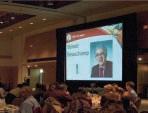
DR. DEBORAH A. SPRATT, P.GEOL.
The L.C. Charlesworth Professional Service Summit Award® is presented annually to a Member of APEGGA who has served her or his profession diligently for many years and made substantial contributions to the operation of the Association and the advancement of its professional status.
The 2011 recipient is Dr. Deborah Spratt, P.Geol., a University of Calgary Geoscience Professor. An ardent promoter of Professional Geoscientists and compliance with Alberta’s laws, she also advises geoscience students on how to choose optional courses that will qualify them for Geologist-inTraining status soon after convocation.
2011 Recipient APEGGA L.C. Charlesworth Professional Service Summit Award ®
As APEGGA’s representative on the Canadian Geoscience Standards Board (CGSB) she helped to set the national geoscience knowledge standards at a level on par with APEGGA’s. Dr. Spratt was one of four members of the team that drafted the Geoscience Knowledge and Experience Requirements for Professional Registration in Canada and is now part of the CGSB working group developing and harmonizing application procedures for internationally trained geoscientists.
For more information on Dr. Spratt, P.Geol., and the APEGGA Summit Awards® visit www.apegga.org.
A message from the CSPG Vice President, Robin Mann
Increasing the Visibility of the CSPG
Seven months ago I had the honour of being electedto the position of Vice President for the CSPG. This was my first time participating as a candidate in a CSPG election, and it was great to see the interest the election garnered. The number of members who participated in the vote was encouraging and spoke to passion within the membership. It is the intention of the current Executive to capitalize on that passion by running elections each year for at leastthe positions of Vice President and Assistant Finance Director. If candidatescan be found, we would also love to have annual elections for all Assistant Director positions. As an Executive, we truly believe that elections are a positive process because elections allow our membership to bring different and diverse experience and opinions to the Board table on an annual basis. The other benefit of regular elections is that the process of seeing your peers put their names forward engages the membership and puts the CSPG top of mind.
Building off the success of last year’s election, the CSPG has made this year a year of ‘bringing things f orward.’ We a re committed to taking steps that will bring the work of the CSPG into the spotlight. To this end, one of our major projects has been to make the CSPG and the Executive more transparent and visible. One of the reasons I ran in last year’s election was my personal belief that the CSPG needs to have a higher profile, both within the energy industry and acrossCanada. The CSPG has a significant amount of knowledgeable talent within our membership and our collective ‘brain trust’ could be utilized even more as a tremendous scientific source, capable of providing even more education on the many aspects of earth sciences to the
public as a whole. In order to reach out to even more people than we do now, we need to make the CSPG more visible and definitely more accessible.
Over thenext year, we have identified two initiatives that will serve to increase our profile, both to our members and to the public. The first is the creation of a new website and the second is our new office location. Both of these initiatives have the ability to increase the profile of the Society, preparing us to show off our scientific prowess in both earth sciences and theenergy industry. As our office lease at 640 – 8th Avenue is coming due at the end of June 2011, the Executive has been searching for a more visible location for the CSPG office. We recently signed a new lease for space at 333 – 5th Avenue SW. This ground-floor officelocation offers the CSPG many advantages: it is in the center of downtown, making it physically accessible to a large number of our members; it is at street level and just below one of the busiest +15 intersections, offeringthe Society an opportunity to physically show ourselves to the public; and, the central location will give all of our committees a more central location for meetings and increase opportunities for members to interact with the CSPG staff.
One of the significant changes associated with the move is that our new office space will not be shared with the CSEG. Even though there are a number of advantages in having both Societies at the same location, the two Societies have a number of differences in their operation plans for the immediate future. The good news is that the CSEG will a lso be moving office locations, and have selected a new space that is relatively close to the new (Continued on page 7...)
CORPORATE SPONSORS
AAPG
AGAT LABORATORIES
APACHE CANADA LTD.
APEGGA
ARC FINANCIAL CORPORATION
AYRTON ExPLORATION CONSULTING LTD
BAkER ATLAS
BLUEBACk RESERVOIR
BOYD PETROSEARCH
CANADA BROkERLINk
CANADIAN NATURAL RESOURCES LTD
CASEY & ASSOCIATES
CENOVUS ENERGY INC.
CGG VERITAS
COLORADO SCHOOL OF MINES
CONOCOPHILLIPS CANADA LIMITED
DEVON CANADA CORPORATION
DIVESTCO INC.
ENCANA
ENERPLUS RESOURCES FUND
FUGRO AIRBORNE SURVEYS CORP.
FUGRO – JASON
GEOEDGES INC.
geoLOGIC systems ltd.
GEOMODELING TECHNOLOGY CORP.
GEOSTRATA RESOURCES INC.
GEOVARIANCES
HALLIBURTON ENERGY SERVICES
HUNT OIL COMPANY OF CANADA
HUSkY ENERGY INC.
IHS
IMPERIAL OIL RESOURCES
LARIO OIL & GAS COMPANY
LITTLE ROCk DOCUMENT SERVICES
LORING TARCORE LABS LTD.
MJ SYSTEMS
MURPHY OIL COMPANY
NEURALOG
NExEN INC.
PENN WEST ENERGY TRUST
PETROCRAFT PRODUCTS LTD.
PLUSPETROL
PROVIDENT ENERGY LTD.
RPS BOYD PETROSEARCH
RPS ENERGY
SCHLUMBERGER CANADA LTD.
SENSOR GEOPHYSICAL LTD.
SHELL CANADA LIMITED
SPROULE ASSOCIATES LIMITED
SUNCOR ENERGY INC.
TALISMAN ENERGY
TOTAL E&P CANADA LIMITED
TOURMALINE OIL CORP.
TUCkER WIRELINE LTD.
WEATHERFORD LABORATORIES
AS OF MAY 10, 2011
(...Continued from page 5)
CSPG office (one block away), so we remain close enough to continue working together.
We anticipate moving into our new offices by September 1, 2011. Over the summer, the existing office will be closed and all CSPG services and communications will be handled remotely. If you are a member who usually phones the CSPG office for information or simply uses the website, the new office location may not have a huge effect on you, but come September, we hope to see many more members stopping by the new location
to se e firsthand the services offered by the Society and to meet the CSPG’s great staff.
The second initiative I mentioned as part of our plans to increase the profile of the CSPG is the development of a new website, which is scheduled to launch this fall. The construction and design of the new website has been happening over the past year thanks to the dedicated efforts of our Communications Directors (Steve
Hubbard and Jim Barclay) and Jeremy Sherry from the CSPG office. The new site is being developed to provide an avenue for increased technical and social content. The site will be very dynamic and we anticipate it will serve as an interactive tool for all of our members. It will include CSPG news, Executive Committee comments and activity, an interactive calendar, a job board, “up to the minute” course and field trip information, online book purchasing (but we also hope you come to the new office to browse the book selection), links to other georesources, and of course, networking options. The new site’s improved graphics and functionality will make it one of the premier geosciences sites on the internet.
With a new centrally located office location and a more interactive website, the CSPG is entering the first stages of increasing our visibility. The Executive will be working hard over the next couple of years to build prominence for the Society, showcasing the great work we do for the members, educational institutions, and the public in general.
technicaL Luncheons JUNE LUNCHEON
A major breakthrough in fracture recognition from seismic –important implications for resource operations and recoveries
SPEAKER
Ralf Oppermann OPPtimal Exploration and Development Pty Ltd.
11:30 am
t hursday, June 9, 2011 c algary, te L us c onvention c entre c algary, a lberta
Horizontal well targeting fractures in Chalk & Shales
Webcasts sponsored by
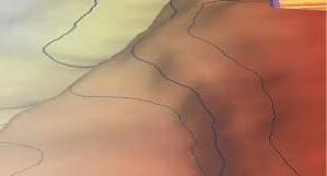
No seismic faults identified or predicted from Reflectivity data: ‘sub-seismic’ faults “hit and miss” fracture development drilling
Fault identification: multiple seismic faults penetrated by well: ‘sub-visual’ faults targeted fracture development possible !
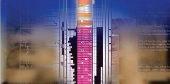
Figure 1. High-resolution fault extraction visualises small-scale spatial changes in amplitude, frequency, or phase content of 3D seismic data, and challenges perceptions of what can and can not be identified with seismic data. Comparison and calibration of seismic fault extractions with faults identified in wells (from core, image logs/dipmeter, log correlation) helps to groundtruth extractions and assess the true seismic fault resolution of a particular data set at objective level.
Please note: the cut-off date for ticket sales is 1:00 pm, monday, June 6, 2011. csPg member ticket Price: $42.00 + gst. non- member ticket Price: $45.00 + gst.
Each CSPG Technical Luncheon is 1 APEGGA PDH credit. Tickets may be purchased online at https://www.cspg.org/eSeries/source/Events/ index.cfm.
Fault and fracture networks can significantly impact reserve recovery and productivity, and can also have significant effects on
FRACDATABASE
Optimize Your Completion Success
» Reliable & Value-Added: We database and summarize the entire completion operation.
» Expanding Dataset: Growing rapidly, driven by client requests.
Contact us for a live demonstration 403.269.3644 info@canadiandiscovery.com www.fracdatabase.com
drilling, mining, and the safety of resource operations. Due to this, various automated fault-extraction techniques have been developed for 3D seismic data in recent years. These techniques aim to support or replace manual fault-mapping efforts, which are typically labour-intensive, timeconsuming, imprecise, and subjective. Ultimately, automated fault-extraction offers the opportunity to replace the interpretation of faults with the direct measurement of faults.
This talk will present an innovative and ‘world-first’ method that has been developed to integrate highest-resolution 3D image processing results with the detailed calibration and review of various seismic, well, and mining data. It will be shown that the method delivers groundbreaking insights into the physical description of resources (Figure 1).
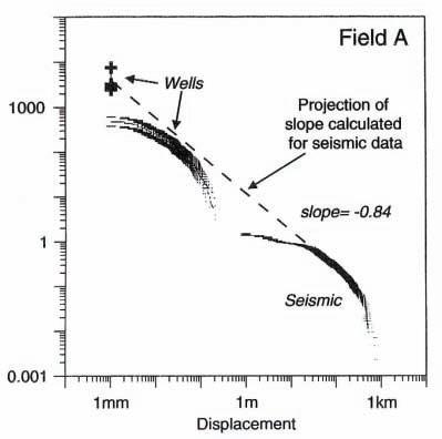
Properly calibrated fault and fracture network volumes deliver faster and more reliable and objective fault evaluations, and a better understanding of structural geometries a nd f ault populations. The key benefit of hi-res, automated fault extraction, however, is a marked increase in fault resolution, which results in a significant increase in the number of medium-sized faults that are identified from seismic (i.e., faults with displacements between 30 and ca. 5m for deep/low-resolution 3D surveys; Figure 2).
With decreasing fault throw (i.e., reflector offset) visual interpretation becomes more and more challenging and subjective, and visual fault-mapping confidence decreases accordingly. This is where automated fault extraction can help to objectively and more confidently visualise faults, particularly
Oil & Gas Cut-off visual fault mapping (20-30m throw)
Figure 2. Comparison of visually mapped seismic fault-throw data with well displacement data (modified from Needham et al., 1996). Displayed also are the cut-off ranges for visual fault mapping from deep, lowresolution oil and gas 3D surveys and shallow, high-resolution Coal Mining 3D surveys. These cut-offs for low and hi-res 3D surveys can both be lowered by automated fault extraction.
faults with small displacement. Automated fault extraction reduces the cut-off for seismic fault recognition and can provide information on faults at ‘sub-visual’ level, approaching the true seismic resolution limit for the detection of faults in a particular data set. These sub-visual, or medium-scale faults are currently incorrectly, but consistently and industry-wide, included into the subseismic and ‘un-mappable’ category by many geoscientists, but can in fact be extracted from seismic data with latest technology, experience, and careful calibration with other data. It follows from this, that most 3D surveys in the resource industries are currently under-utilized when it comes to fault identification, as an entire mediumsized, sub-visual (but not sub-seismic) fault population can be extracted from already existing data with relatively little effort.
Examples from fractured and compartmentalised reservoirs around the world, as well as unconventional reservoirs (tight gas, shale gas, basement reservoirs) demonstrate that the new techniques can delineate potential fluid barriers, fluid conduits, or geomechanical instability areas in the subsurface at a much higher resolution than achieved by other current methods.
With the increased resolution, much higher fault/fracture densities are found than
were previously recognized. Instead of identifying, for example, only the 10 largest faults in a field through visual mapping efforts, 100 or 1,000 smaller faults can be additionally made visible through hi-res automated fault extraction.
This, in turn, allows the identification of many fault penetrations in wells that were previously not recognized from seismic data, or even from well data, particularly in intervals where no core, dipmeter, or image logs have been acquired. These newly identified seismic fault penetrations are often directly linked with drilling problems (e.g., fluid losses, geomechanical/borehole stability issues) or production problems (e.g., water or gas channelling along fault planes, compartmentalisation, etc.). Importantly, they can be also directly linked with hydrocarbon shows and productivity, especially in fractured and unconventional reservoirs, where these faults can provide direct access to productive natural fracture networks.
The comparison of the new hi-res seismic fault and fracture networks with drilling and production issues suggests that a new dimension in the visualization and understanding of resources has been opened. The presentation will aim to show that a focused application of the new
technology workflows can deliver increased recoveries from resources, and that it can also result in safer, cheaper, and more successful drilling and mining operations. As such, the new techniques are proposed as Best Practise tools for exploration and development planning and execution.
BIOGRAPHY
Ralf Oppermann is an independent geoscience consultant with 21 years of international experience in the Oil and Gas industry, working as a seismic interpreter and geologist in integrated, multi-disciplinary exploration, appraisal and development teams. During his career, he has worked as international staff for various Shell Operating Companies in the Netherlands, U.K., Germany, Malaysia, and New Zealand, as well as working with Chevron in Australia.
In 2008, Ralf founded OPPtimal Exploration & Development Pty Ltd. as a technology service company, to provide new and leading-edge volume interpretation workflows to companies active in oil and gas, shale gas / oil, coal seam gas / coal bed methane, underground gas storage, geosequestration, geothermal, groundwater, coal mining, and ore mining. His company is located in Perth, Australia, and has so far performed fault visualization studies on assets in North America, Europe, M iddle E ast, Asia, and Australasia, for oil and gas, shale gas, geothermal and coal mining companies. Currently, Ralf is working on one of the largest oil fields in the world, a fractured carbonate reservoir in the Middle East.
Ralf is particularly keen to perform further studies on shale gas and coal seam gas assets in North America, as very few of these assets in Australia are currently covered with 3D seismic. He is also trying to find a company who is interested in performing a comparison of his hi-res fault extractions with microseismic data.
Ralf holds an M.Sc. in Geology/Palaeontology and B.Sc. in Business and Economics from the University of Göttingen in Germany. He is a member of the European Association of Geoscientists and Engineers (EAGE), the Formation Evaluation Society of Australia (FESAus), the German Federation of Geologists (BDG), the Petroleum Exploration Society of Australia (PESA), the Petroleum Exploration Society of Great Britain (PESGB), and the Society of Petroleum Engineers (SPE).
DIVISION TALKS GEOMODELING DIVISION
Application of Ensemble Kalman Filter as a data assimilation technique for characterization of heavy oil reservoirs
SPEAKER
Yevgeniy Zagayevskiy Centre for Computational Geostatistics School of Mining and Petroleum Engineering University of Alberta
12:00 Noon
Wednesday June 29, 2011 Husky Conference Room A +30 South Tower 707 8th Avenue SW Calgary, Alberta
ABSTRACT
The success of most oil recovery methods used for bitumen extraction in northern Alberta heavily depends on the permeability distribution. Realistic estimation of the permeability values in space can significantly improve oil recovery factor, leading to more efficient field development. For instance, a key concern in modeling of petroleum reservoirs, where steam-assisted gravity drainage (SAGD) is used, is proper understanding of the spatial distribution of the vertical permeability tensor. The vertical permeability determines flow communication between injection and production well pairs and the connectivity to the reservoir. Core data, dynamic production data, and time-lapse seismic attributes can be used to constrain the permeability distribution. However, the amount of core data is limited and sampled unevenly and sparsely. Dynamic data are a more abundant source of information once production has commenced, but it must be properly integrated into the reservoir model. The Ensemble Kalman Filter (EnKF) is proposed as an automatic
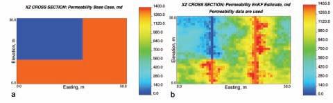
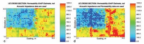
Figure 1. Comparison of EnKF estimates of permeability derived using different data sets to base case: a) permeability base case, b) permeability estimate when permeability data are used, c) acoustic impedance data are used, and d) permeability and acoustic impedance data are used. It is obvious that incorporation of additional data has improved estimation results.
data assimilation technique based on an ensemble of realizations. Its application leads to proper petroleum reservoir characterization, where all available data are used to constrain the permeability distribution and the relationship between variables is preserved. History matching serves as a goodness criterion for the quality of permeability estimates. The background of EnKF is highlighted with both global and local updating approaches. Its im plementation details and limitations are discussed with small 2D case studies. Core data, such as porosity and permeability, abundantly available temperature data from surveillance wells and 4D seismic attributes are used to constrain the permeability distribution. CMG’s thermal flow simulator (STARS) and a temperature- and pressuredependent Gassmann’s fluid substitution model are used to establish the relationship between variables. The technique is reasonably simple to implement and relatively precise, but in some cases may be computational expensive.
BIOGRAPHY
Yevgeniy Zagayevskiy is an M.Sc. student at the School of Mining and Petroleum Engineering, University of Alberta, and a research assistant at the Centre for Computational Geostatistics, directed by Professor Clayton Deutsch. He graduated from Kazakh-British Technical University (Almaty, Kazakhstan) in 2009 with a bachelor’s
degree in petroleum engineering. His main research work is focused on application of EnKF in petroleum reservoir characterization. He has also done some work in developing a framework of sensitivity analysis based on regression approach.
INFORMATION
There is no charge for the division talk and we welcome non-members of the CSPG. Please bring your lunch. For details or to present a talk in the future, please contact Weishan Ren at (403) 233-3428, e-mail: weishan. ren@conocophillips.com.
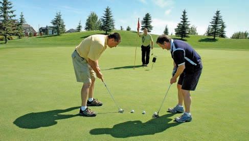
Have you registered for upcoming CSPG Social Events?
• Classic Golf
• Mixed Golf
• 10K Road Race and 5K Fun Run
RJWDOUGLASMEDAL CALLFORNOMINATIONS
The RJW Douglas Medal is awarded annually by the Canadian Society of Petroleum Geologists for outstanding scientific contributions to the understanding of sedimentary geology in Canada, commending major contributions to regional tectonics, petroleum, and structural geology.
The award is open to all geologists who follow the example of Bob Douglas in contributing to the development of Canadian sedimentary, petroleum, and structural geology.
Nominations for the award of the medal must be endorsed by at least three members of the CSPG. Nominations may be proposed at any time, but to be considered for a particular year, they must be received by the Society before September 1
The sponsors of a nominee for the award should supply:
A curriculum vitae (outlin g the nominee’s career and previous honours or distinctions).
A list of publications by the nominee.
A summary of the nominee’s achievements in a form suitable for use as a citation for the award.
An analysis of the nominee’s achievements, highlighting the contributions for which he or she is being recognized, and relating these to the appropriate publications in the bibliography.
The last item of information is a key part of the nomination and should convey the magnitude and scope of the nominee’s scientific contributions, with comments on the influence that these contributions have had on others. An example of a submission may be provided on request.
Completed nominations should be sent to:
Margot McMechan
CSPG Douglas Medal Committee Chairman, c/o Margot McMechan
GSC – Calgary
3303, 33rd Street NW, Calgary, Alberta T2L 2A7
Telephone (403) 292-7154
Email: mmcmecha@nrcan.gc.ca
Five Great Days of the Finest Geoscience Training for One Low Price
Courses include:
❍ Fundamentals of Petroleum Geoscience—Bend
❍ Fundamentals of Siliciclastic Sequence Stratigraphy—Holbrook
❍ Getting Started in Fluvial Stratigraphy—Holbrook
❍ Creativity in Petroleum Exploration—Beaumont & Strickland
❍ Using Well Log Analysis for Reservoir Volumetrics—Erickson
❍ Practical Oil-field Development: Important Applications of Geol. & Petrol. Engineering—Erickson
❑ Computer Mapping for Petroleum Exploration—Leetaru
❑ Hydraulic Fracturing for Geologists—LaFollette
❑ Reservoir Engineering for Petroleum Geologists—Green
Hosted by the Norris Conference Center: 304 Houston St. Ft. Worth, TX 76102
Phone: 817-289-2400
Fax: 817-289-2411
Special AAPG group rates at nearby hotels.
Registration and information:
Toll-free (U.S. and Canada) 888-338-3387, or 918-560-2650
Fax: 918-560-2678
E-mail: educate@aapg.org
Download a registration form at: www.aapg.org/education/sec.cfm
UNICORNS IN THE GARDEN OF GOOD AND EVIL: Part 8 – Igneous and Metamorphic Reservoirs
| By E. R. (Ross) Crain, P.Eng.
Unicorns are beautiful, mythical beasts, much sought after by us mere mortals. The same is true for petrophysical models for unconventional reservoirs. This is the eighth in a series of review articles outlining the simple beauty of some practical methods for log analysis of the unusual.
IGNEOUS AND METAMORPHIC BASICS
Igneous and metamorphic rocks form reservoirs in many parts of the world. Reservoir quality varies and most benefit from natural fractures. Although some geologists believe the hydrocarbons in some granite reservoirs comes from deep in the earth, the majority of these reservoirs can be shown to contain hydrocarbons that migrated from conventional sedimentary sources.
As a generalization, metamorphic rocks are rocks that have been exposed to high heat and pressure. The main causes are:
• Contact metamorphism – changes in the rock due to heat from a nearby magma source.
• Regional metamorphism – changes caused by widespread elevated heat and pressure.
• Hydrothermal metamorphism – chemical changes in the rock due to the circulation of hot liquids through the rock fractures.
• Fault-zone metamorphism –metamorphic changes caused by friction at fault movements.
My personal experience is that density, neutron, sonic, and photoelectric values for metamorphic rocks are the same as the sedimentary equivalent, although this may not be universally true.
The change in the rock is based on the amount of heat and pressure applied to it, as well as the fluids available during the metamorphic processes. Changes that occur during metamorphism include:
• Small crystals re-form to create larger crystals of the same minerals (re-crystallization).
• New minerals are created from the original mineral composition (neomorphism).
• New minerals are created by gaining or losing elemental components.
Specific sedimentary rocks become specific metamorphic rocks, as shown in Table 1.
Igneous rocks are classified in several ways – by composition, texture, and method of emplacement. Generally speaking, the composition (mineral mixture) determines the log response, the texture determines the name used for the mineral mixture, and the method of emplacement determines the texture and internal porosity structure (if any).
Intrusive igneous rocks are formed inside the earth. This type of igneous rock cools very slowly and is produced by magma from the interior of the earth. They have large grains, may contain gas pockets, and frequently have a high fraction of silicate minerals. Intrusions are called sills when oriented
Basalt Schist or Amphibolite
Granite Schist
Rhyolite Schist
Table 1. Metamorphic rock origins.
roughly horizontal and dikes when near vertical. Extrusive igneous rocks form on the surface of the earth from lava flows. These
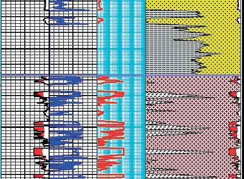
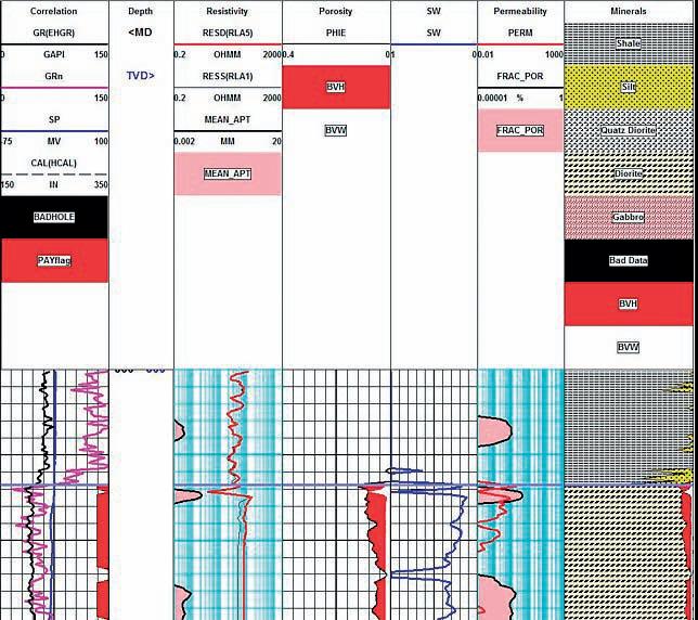
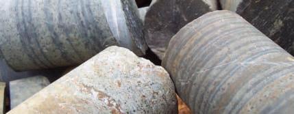
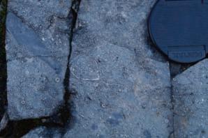
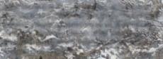
Figure 2. Granite Wash (yellow) and shale (gray) above granite (white) and diorite (tan). Porosity and lithology are calculated from conventional density, neutron, and PE methods. Both zones are radioactive, so the GR is not used for shale volume.
cool quickly, resulting in small grain sizes. They typically contain little to no gas from the initial formation.
Both intrusive and extrusive rocks may contain natural fractures created by contraction while cooling, and may have carried other rock fragments with them, called xenoliths. Intrusive rocks may alter the rocks above and below them by metamorphosing (baking) the rock near the intrusion. Extrusives only heat the rock below them, and may not cause much alteration due to rapid cooling. Extrusives can be buried by later sedimentation, and are difficult to distinguish from intrusives, except by their chemical composition and grain size.
The mineral composition of an igneous rock depends on where and how the rock was formed. Magmas around the world have different mineralogical compositions.
• Felsic igneous rocks are light in color and are mostly made up of feldspars and silicates. Common minerals found in felsic rock include quartz, plagioclase feldspar, potassium feldspar (orthoclase), and muscovite. They may contain up to 15% mafic mineral crystals and have a low density.
• Mafic igneous rocks are dark colored and consist mainly of magnesium and iron. Common minerals found in mafic rocks include olivine, pyroxene, amphibole, and biotite. They contain about 46-85% mafic mineral crystals and have a high density.
• Ultramafic igneous rocks are very dark colored and contain higher amounts of the same common minerals as mafic rocks, but with about 86-100% mafic mineral crystals.
• Intermediate igneous rocks are between light and dark colored. They share minerals with both felsic and mafic rocks. They contain 15 to 45% mafic minerals.
• Plutonic and volcanic rocks generally have very low porosity and permeability. Natural fractures may enhance porosity by allowing solution of feldspar grains. Some examples with average porosity as high as 17% are known.
Tuffs and tuffaceous rocks have high total porosity because of vugs or vesicles in a glassy matrix. This is most common in pyroclastic deposits. Interparticle porosity may also exist. Some effort has to be made to separate ineffective microporosity from the total porosity. Pumice (a form of tuff) has enough ineffective porosity to allow the rock to float!
The numerical data in Table 3 has worked well in igneous reservoirs using standard lithology models given earlier in this chapter (Mlith-Nlith, DENSma-Uma, etc). The table is in imperial units. If you work in metric
units: divide neutron values by 100; multiply density by 1,000; and multiply sonic by 3.281. All these values have a moderate range (+/10%) and some tuning may be necessary. Don’t forget to convert to metric as needed.
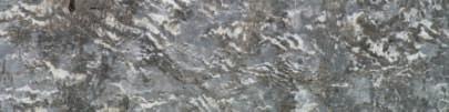
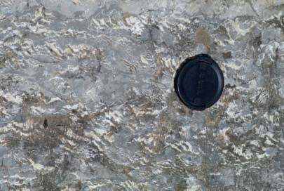
Figure 3. Diorite intrusion covered by shale, open fracture visible as low resistivity spike at top of diorite. Fracture aperture (Track 2) and fracture porosity (Track 5) are from resistivity image processing.
Table 2. Igneous rock classification.
Table 3. Matrix properties for igneous rocks.
Use these matrix values in matrix density or PE crossplots.
Since a typical log suite can solve for three or four minerals at best, you need to chose the dominant minerals and zone your work carefully. If you have additional useful log curves, you might try for more minerals or set up several four-mineral models in a probabilistic solution. A good core or sample description will help you choose a reasonable mineral suite.
Sometimes lithology is determined by triggers. For example, where basalt beds are interspersed between conventional granites or quartzites, it is easy to use the PE or density logs to trigger basalt, leaving the remaining minerals to be defined by a twoor three-mineral model. This approach is widely used in sedimentary sequences to trigger anhydrite, coal, or salt.
Two crossplots are useful for rock identification in metamorphic rocks, as shown in Figures 5 and 6.
METAMORPHIC SAND / GRANITE
R
ESERVOIR EXAMPLE
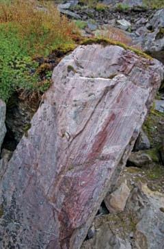
Figure 7 is a granite / metamorphic rock example from Indonesia. The reservoir has a porosity-enhanced (possibly by fracturerelated solution) granite at the base, metamorphosed sandstone and shale above, topped by unmetamorphosed sandstone and shale. Porosity is moderately low throughout, but the gas column is continuous. Interbedded shales (schist or gneiss in the metamorphic interval) are present but do not act as barriers to vertical flow.
Figure 4. Typical igneous rock mineral composition (courtesy Schlumberger). (Continued on page 16...)
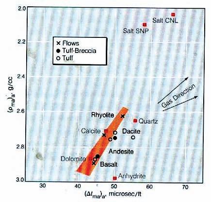
Figure 5. DENSMA vs. DELTMA Plot (courtesy Schlumberger).
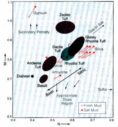
Figure 6. Mlith vs. Nlith Plot (courtesy Schlumberger).
(...Continued from page 15)
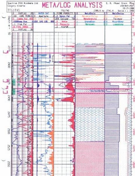
In this case, the mineralogy was triggered by quantitative sample descriptions, which in turn were keyed to raw log response to minimize cavings and depth control issues. Porosity and water saturation were derived from conventional log analysis methods. The reservoir is naturally fractured and a fracture-intensity curve was generated from anomalies on the open-hole logs. This was compared to the fracture intensity from resistivity micro-image log data.
Quantitative sample description of mineral composition is shown in track five (right-hand track). Interpreted lithology is in track four; computed porosity in track three (middle track). The log analysis porosity matches core reasonably well (center track) and open-hole fracture indicators (right edge of track one) correspond to resistivity image log data (left edge of track two).
FRACTURED GRANITE R ESERVOIR EXAMPLE
Most people forget that there are many unconventional reservoirs in the world,
which include igneous (extrusive and intrusive) and metamorphic rocks. Granite reservoirs are prolific in Viet Nam, Libya, and Indonesia. Lesser-known granite reservoirs exist in Venezuela, United States, Russia, and elsewhere. Indonesia is blessed with a combination sedimentary, metamorphic, and granite reservoir with a single gas leg. Japan boasts a variety of volcanic reservoirs.
Log analysis in these reservoirs requires good geological input as to mineralogy, oil or gas shows, and porosity. Good coring and sample-description programs are essential, as are production tests. The analyst often has to separate ineffective (disconnected vugs) from effective porosity and account for fracture porosity and permeability. All the usual mineral identification crossplots are useful, but the mineral mix may be very different than that in normal reservoirs. Many such reservoirs seem to have no water zone and most have unusual electrical properties (A, M, N), so capillary pressure data is usually needed to calibrate water saturation.
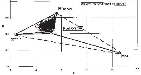
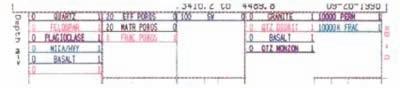
In an example from the Bach Ho (White Tiger) Field in Viet Nam (see Figures 9, 10, and 11), the mineral assemblage was defined by the ternary diagram in Figure 8. The three minerals (quartz, feldspar, and plagioclase) were computed from a modified Mlith vs. Nlith model, in which PE was substituted for PHIN in the Nlith equation. If data fell too far outside the triangle, mica was exchanged for the quartz.
Figure 9. Mlith vs. Plith crossplot for granite (micaceous data excluded).
Figure 7. Metamorphic / Granite example with quantitative sample description, calculated lithology, log analysis porosity, saturation, and permeability, with core porosity and permeability overlay. A production log cumulative productivity curve was overlaid on a similar curve generated from log analysis flow capacity (KH). Since this is a gas play, cutoffs are quite liberal.
Figure 8. Ternary Diagram for Granite.
Three rock types – granite, diorite, and monzonite – were derived from the three minerals. A trigger was set to detect basalt intrusions. A sample crossplot in Figure 9 shows how the lithology model effectively separates the minerals.
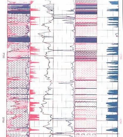
A sample of the log analysis plot is shown in Figure 10. The average porosity from core and logs is only 0.018 (1.8%) and matrix permeability is only 0.05 mD. However, solution porosity related to fractures can reach 17% and permeability can easily reach higher than several Darcies. Customized formulae were devised to estimate these properties from logs, based on core and test data. My colleague, Bill Clow, devised most of the methods used on this project.
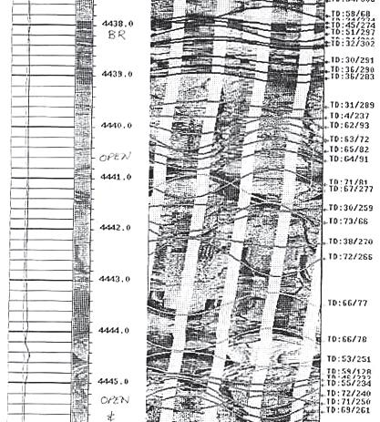
Note the fracture porosity and permeability derived from open-hole log data. Fracture porosity from resistivity micro-scanner logs was also computed where available to help control the open-hole work. A black and white resistivity image log, Figure 11, shows some of the fractures. Both high- and low-angle fractures co-exist.
It is clear that non-conventional reservoirs may need some extra effort, customized models, and unique presentations. Everything you need to develop these techniques can be found elsewhere in my handbook (Crain’s Petrophysical Handbook on CD-ROM). The mineral properties need to be chosen carefully, but the mathematical models don’t change too much.
ABOUT THE AUTHOR
E. R. (Ross) Crain, P.Eng., is a consulting petrophysicist and a Professional Engineer with over 45 years of experience in reservoir description, petrophysical analysis, and management. He has been a specialist in the integration of well log analysis and petrophysics with geophysical, geological, engineering, and simulation phases of oil and gas exploration and exploitation, with widespread Canadian and Overseas experience.
His textbook, “Crain’s Petrophysical Handbook on CD-ROM” is widely used as a reference to practical log analysis. Mr. Crain is a Honourary Member and Past President of the Canadian Well Logging Society (CWLS), a Member of Society of Petrophysicists and Well Log Analysts (SPWLA), and a Registered Professional Engineer with Alberta Professional Engineers, Geologists and Geophysicists (APEGGA).
Figure 10. Depth plot for a granite reservoir.
Figure 11. Resistivity micro-scanner image in a granite reservoir – dominant dips are 60 to 75 degrees from horizontal.
2011 CSPG STANLEY GOLD
“This pioneer and explorer in geology, engineering and natural gas technology bequeathed a fundamental knowledge, years ahead of his time and was considered by many a virtual Leonardo da Vinci of the Petroleum Industry. Slipper, our first President, deserved the honour (unbeknownst to him) of our highest award in the Canadian Society of Petroleum Geologists” (Aubrey Kerr).
The medal is presented annually by CSPG for outstanding contributions to oil and gas exploration in Canada. The contributions of the winner of this award should encompass a number of activities related to aspects of petroleum exploration. Such activities include: initiating and or leading exploration programs, significant discoveries on new or existing exploration trends, teaching and or training of explorationists, and
involvement in and leadership within geological societies and professional organizations.
The Committee is currently calling on the CSPG membership to provide additional nominations for this prestigious award. The Award winner must be a CSPG member and should be able to attend the awards presentation to be held in 2012.
Please include an updated biography, bibliography and letters in support of your nominee.
Nominations should be emailed before Thursday, September 15, 2011 to:
Email: clinton.tippett@shell.com and kasandra.klein@cspg.org (please send your nomination to both addresses)
Phone: Clint Tippett, Chairman, 403.691.4274 or Kasandra Klein, Member Services Coordinator 403.513.1229
T HE ANALYSIS OF FRACTURES IN PETROLEUM RESERVOIRS : Part 1
| By Paul A. MacKay
INTRODUCTION
Fracture analysis in petroleum systems is a rapidly expanding field of study in the Earth Sciences. Interest in the analysis of fracture systems is driven by the recognition of the essential role that fractures play as fluid conduits within the earth’s crust. For the past few decades the role of the importance of fractures as fluid pathways has grown. Much of this recognition has been driven by the petroleum industry as it seeks new unconventional reservoirs to replace the declining production from older more conventional reservoirs. The challenge in fracture analysis is no longer the identification of fracture systems but rather to quantify the effect of the fractures on fluid migration and the effectiveness of transmitting fluids through rock.
Initial studies in fracture analyses were directed towards material strength issues. Essentially, at what point does the structural integrity of materials fail? Fractures were studied as a possible contribution to failure mechanism including slope stability problems, mine safety issues, well bore stability concerns to name a few. Some of the first recognition of fractures as a significant factor in fluid conductivity came with the search of looking for repositories for nuclear waste. Several underground sites within crystalline rock were investigated for the feasibility of storing waste fluids from nuclear reactors. It was consistently found that deep open fracture networks made potential sites an unsuitable option due to the inability of the rock to contain the injected waste (Fabbro, 2010).
Efforts into understanding fracture networks as a contribution to the reservoir permeability were initially investigated in the late 1950s and early 1960s as a means of explaining production from wells that did not fit the classic reservoir models. Experimental work into rock failure on core plugs carried out by Sterns and Friedman (1972) at Texas A&M helped develop the concept of conjugate fracture systems and the link between fracture patterns and the causal stress orientations. This model of fractures persists through much of the literature with little change from its inception.
A significant renewal in the interest in fractures as an enhancement to reservoir permeability occurred in the 1980s and 1990s as oil and gas projects were drilled to pursue tight reservoirs in structurally complex geologic settings. These wells were dependent on open fracture systems to provide economic delivery of hydrocarbons (Morrison and Cooper, 1992). In this case, the fracture development was recognized to be a combination of the classic models developed by Sterns and Friedman, as well as fracture development created by the bending moment in the rock associated with folding.
As the role of fractures relative to reservoir deliverability became more accepted, a strategy developed to pursue zones that had hydrocarbon indications (shows) but did not have the characteristics of a conventional reservoir (matrix porosity and permeability). The rush to pursue coalbed methane projects and the recent interest in shale reservoirs has pushed the analysis of fracture systems to the forefront of exploration (Durham, 2010). Long-reach horizontal drilling, image logs, microseismic, and multi-stage fracs are all new technologies developed to help identify and exploit fracture systems.
Despite this strong effort to identify natural and induced fractures systems, fracture analysis remains largely qualitative (good
vs. poor fractured zones), and effort to quantify the fracture systems has languished. As the need to quantify the resource and establish economic criteria to rank the quality of resource projects intensifies, the analysis of fractures will be driven to greater precision. Fractures are a fabric within the rock that remains elusive to describe in anything but general terms. The challenge will be to describe the fracture systems with a reasonable degree of accuracy and to accurately predict the path and intensity of newly induced fracture systems.
ROCK FAILURE
Before describing fractures, it is worthwhile to investigate fracture generation. Fractures are failure surfaces within the rock volume. They are a response to stress conditions in the rock and, as such, record strain. Classical strain studies within rock deal with the concept of penetrative strain, a total rockvolume response to stress conditions within the rock over some finite volume within the rock. However, fractures are discrete failure or strain surfaces in the rock. Two parallel fractures form as a strain response to stress within the rock, but the volume between the two failure systems may not record any strain. This makes analysis of fractures using classically developed strain-analysis techniques difficult.
(...Continued from page 19)
Fractures form, or stated more simply, rock breaks when the stress conditions within the rock exceed the strength characteristics of the rock. Failure in rock is a function of the stresses acting on the rock and the mechanical strength of the rock. The stresses acting upon the rock are determined by the depth of burial (vertical stress) and generally tectonic forces (horizontal stresses) that develop as a result of plate-to-plate interactions. These tectonic forces are generally greatest on the flanks of the plate and penetrate into the plate’s interior. Local conditions can also influence the direction and magnitude of the stress vectors, such as differential compaction, local folding, and faulting, to name a few. The mechanical strength of the rock is determined by the physical rock properties. For failure to occur, the effective stresses acting on the rock must exceed the physical strength of the rock. In a simple homogeneous isotropic
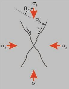
medium, the stresses acting on any plane within the rock volume can be resolved into a normal stress ( sn) and a shear stress (Figure 1). With knowledge of the magnitude and orientation of the principal stresses ( s1, s2 , s3) it is possible to determine the normal and shear stresses acting on any plane within the rock volume.
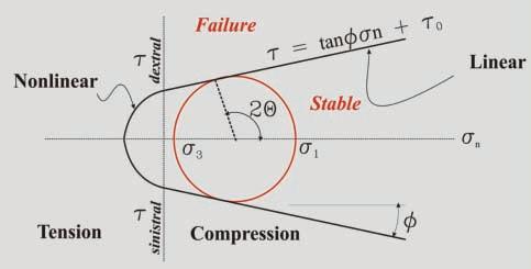
The relationship of the shear stress acting along a surface and the normal stress acting across the same surface is easily described using a Mohr Diagram, which is simply the relationship of shear stress to normal stress in Cartesian coordinates (Figure 2). By convention, if the normal stress is compressive, it is considered positive, whereas tensile stresses are considered negative. A shear stress with a dextral (right-hand) sense of motion is considered positive and sinistral (left-hand) shear stress is considered negative. The principal stresses acting on a rock volume are by definition acting on planes that have no associated shear stress acting along that plane. Thus the principal stresses lie on the horizontal axis of the Mohr Diagram.
In contractional systems, it is convenient to assume that the system is behaving under the conditions of Plane Strain. This means that the intermediate stress ( s2 ) is confining and that there is no motion in and out of the plane perpendicular to the intermediate stress (essentially all the deformation can be described simply with the maximum and minimum principal stresses ( s1 and s3 ). This is a broad simplification and is often not true locally. In the design of fracture stimulation of wells the intermediate stress should be taken into consideration.
The difference in magnitude between the maximum and minimum stress is called the differential stress or the deviatoric stress. The stress conditions acting on any plane within the rock volume are described by a circle on the Mohr Diagram that is defined by the maximum and minimum principal stress. Thus the stress conditions acting on any plane in the rock volume lie on a circle defined by s1 and s3 whose diameter is the differential stress.
The strength conditions of the rock
Figure 1. Stress distribution in an isotropic homogeneous system and how the normal and shear stresses relate to the principal stresses.
Figure 2. Mohr Diagram describing the stress and strength conditions of a rock volume.
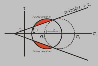
Figure 3. The role of increasing fluid pressure is to shift the Mohr circle to the left, thereby creating failure conditions.
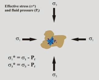
Figure 4. Fluid pressure works against the confining stress such that the effective stress is less than the confining stress.
volume can also be described on the Mohr Diagram. A line separates the stress conditions that are stable from those that are unstable (failure) for a given material. The line approximates a straight line in the compressive field and is known as the Failure Envelope with the general form of y = mx + b. If the stress conditions exceed the strength conditions defined by the line then failure is anticipated. In this case, y is the shear stress and is the normal stress sn . The slope of the line, m, is the rise over the run and is defined as the tangent of the angle that the line makes with the horizontal axis (), and the y-intercept where failure occurs under no compressive stress is known as o and defined as the cohesive strength of the rock (cohesion). Note that in the compressive field the strength conditions approximate a straight line but in the tensile field the strength conditions are not linear and the complexity of the relationship is greatly increased.
Most of these terms are easily understood, except for . This parameter () is a function of the rock properties and is dependent on factors such as the strength modulii, density, anisotropy, lithology, depth of burial, cementation, etc. of the rock. These terms are grouped together under this single term , and is referred to as the Angle of Internal Friction. This is the rock’s resistance to failure or its strength. In the case shown
in Figure 3 the system is critically stressed, meaning that the strength conditions and the stress conditions are balanced at the point of failure, where the stress circle is touching the strength envelope. In this case, if failure should happen it will occur on an oriented plane whose normal stress is theta ( ) degrees away from the maximum principal stress ( s1).
Once the strength-stress relationship of the system is understood, it is a straightforward process to understand how to create failure conditions and fracture a rock or propagate a fault through the rock volume. To create failure, the stress conditions must exceed the strength conditions as defined on the Mohr Diagram. One method of creating failure is to increase the maximum compressive stress while holding the minimum compressive stress constant. In this method, the differential stress increases and the circle grows in diameter to place certain plane orientations into the failure field. Failure will occur on these planes and fractures or faults will propagate through the system. A second method of failure is to decrease the minimum compressive stress thereby increasing the differential stress and causing failure. Any combination of these two effects increases the differential stress and may lead to failure.
Another method to create failure is to increase fluid pressure. At a pore level, fluid
pressure, Pf, is pushing out from the pore in all directions (pressure is not a vector and will have the same magnitude in all directions, unlike stress, which is a vector and has directionality). Hence the fluid pressure works opposite to stress and the effective stress s * is defined as the absolute stress ( s) less the fluid pressure (Pf ) (Figure 4).
The effective stress is less than the principal stresses by the amount of fluid pressure and will shift the circle on the Mohr Diagram to the left (Figure 5). This shift of the Mohr Circle will place certain orientations of the rock into the failure field and fracturing will occur along those orientations.
Since fluid pressure works in all directions s1 and s3 are affected equally such that the effective principal stresses can be defined as:
s1* = s1 - Pf and s3* = s3 - Pf
The result of an increase in fluid pressure is to shift the stress conditions into failure mode.
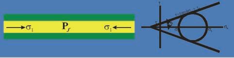
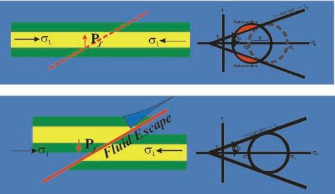
In a contractional setting it is interesting to consider what happens as failure occurs. Consider an example where the system is at critical stress (Figure 5a). As fluid pressure increases the system shifts into failure conditions and the rock breaks (Figure 5b). The break creates a pathway that allows the fluid to escape and results in lower fluid pressure and a return to the stable stress conditions (Figure 5c). In this scenario, the stress conditions always remain critically stressed near failure. It is impossible to release the fluid pressure to such a state as to take the failure conditions deep into the stability field as the normal stresses acting on the failure plane will be allowed to work to close the fluid escape path to prevent excess bleeding of the fluid pressure. Over geologic time, the system will eventually find itself in equilibrium with the overall surface or an overlying seal, but not until the horizontal stresses relax or the source of the elevated fluid pressure is exhausted.
If fluid pressure plays such a critical role in the failure mechanism, what is the source of the additional fluid? In the sedimentary section, the fluids available to the failure mechanism are either water or hydrocarbons. All other fluids that may be available are in such small quantities as to be insignificant. Water is an incompressible fluid and is an excellent source to create elevated fluid pressures, especially in systems that form in poorly lithified rock and systems that are undergoing compaction. In these systems, the compaction process results in elevated fluid pressures conducive (Continued on page 22...)
Figure 5. A critically stressed system near failure conditions (a). Increase in fluid pressure shifts the Mohr Circle to the right into failure conditions (b). The failure of the rock opens up fluid pathways that allow the fluid pressure to escape and the system returns to the critical stress conditions (c).
c.
to failure. In active deformation systems that are propagating through older strata or lithified rock, the use of water as the principal fluid source becomes problematic as the amount of water is limited and the system has compacted in a manner that does not favour the easy transfer of water from one horizon to another. In these cases, the source of the fluid is more likely to be hydrocarbons that formed as the strata are buried and heated ( kreis et al., 2005). The maturation process that converts organic material to hydrocarbons is a volume increase reaction, although the degree and extent that
this happens is variable and dependent on the chemical structure of the organic material.
The formation of the fracture has a range of implications to the rock / fluid system. The fracture forms as a response to the increase in fluid pressure and, as such, has the capacity to move fluids. Thus, all fractures are capable of moving fluids at some point in their inception. Essentially the fracture forms to relieve the growing fluid pressure in the rock. If the fracture does not move fluids, the fluid pressure would continue to build to impossible levels. This has another implication in that the fracture will have a
preferential permeability to the fluid type that is present when the fluid pressure initially formed.
In a rock that has sufficient organic content to be considered a source rock, the generation of the type of hydrocarbon is essential to the relative permeability curves of the fluid system. Nature designs the fracture network to relieve the pressure in the most efficient manner. The fractures will open only as large as necessary to relieve the fluid pressure. If the nature of the fluid is a small molecule, such as gas, then the fracture that forms will likely be small aperture. Conversely, if the fluid creating the pressure has large molecules such as oil, then the fractures will have larger aperture to be able to pass the larger molecule. In this manner, the nature of the fluid that forms the pressure is of critical importance to the size of the aperture of the fracture and greatly affects the relative permeability curves of the system (Figure 6).
In the case of hydrocarbons as the fracturing fluid, there is a slightly more complex attribute to consider. Different kerogen types tend to preferentially form different types of hydrocarbons. Type III kerogen favours the formation of gas, such that the expectation in this setting would be a fracture systems that formed with a small molecule type of fluid. The fractures would have small aperture and have poor relative permeability to a liquid phase (oil or water) but would be permeable to gas. Organic material rich in Type I and II kerogen will tend to form oil, a larger molecule, and as such, will have fractures that have a larger aperture and will have greater permeability to the liquid phase (oil and water).
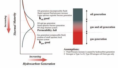
The thermal maturity of the organic material increases complexity of the fracture system in the cases where hydrocarbons are the dominant fracturing agent of the system (Figure 7). As the thermal maturity of a source rock increases the type of hydrocarbon that is generated changes. At relatively low thermal maturity, liquid petroleum is generated. With an increase in the thermal maturity, oil generation reaches a peak. With greater thermal maturity gas becomes the dominant constituent. Not only has the molecule size changed with the increase in thermal maturity, but the relative compressibility of the generated fluid also changes. The early stage of the thermal maturation of hydrocarbons generates oil, an incompressible fluid. This will result in a large regional pressure front creating a regional interconnected fracture system with relatively large aperture and good permeability to oil (Johnson, 2009).
In situations of high thermal maturity the
generating fluid is gas, a compressible fluid. In this case, the fluid pressure is not transmitted significant distances and the fracture system is likely to be more local with poor permeability to liquids. These systems will transmit gas, but if fluids are introduced into the system (such as drilling mud) then the fractures may become blocked and the permeability of the system to gas is compromised.
In the intermediate stage of the maturation levels there are two phases of fluid that form. Liquid petroleum is still being generated, but a gas phase also forms. The pressure release created by the fracturing of the rock will preferentially release gas as it is the smaller molecule. Oil is in the system but the fracture network is partially designed to pass gas and the liquid phase is less mobile. In part, the liquid phase will move but the fracture aperture is smaller and the relative permeability for oil is reduced. The clogging of the fracture system with the liquid phase has the effect of reducing the relative permeability of gas and a partial permeability trap forms that has compromised the fracture systems ability to move either gas or oil. This stage of the maturation pathway has been referred to as the “Permeability Jail”, where neither oil nor gas is easily transmitted.
PERMEABILITY
As previously discussed, fractures are of critical importance with respect to the transmission of fluids within a rock. Given this importance, it is necessary to discuss the term permeability and to grasp the influence that fractures have on this term. Permeability is defined as the ability of a material to transmit fluids. It is defined by Darcy’s law, which relates fluid flow through a material as a function of the pressure gradient (dP/ dl ), the distance (l ), the cross-sectional
area (A), the viscosity ( ) of the fluid, and the permeability (k) of the system.
Q = k (dP/dl ) A / l
Some of the concepts about permeability flow from this law. One is that permeability has directionality. Flow has directionality and, as such, so must permeability. This means that the permeability will differ within a reservoir not only in spatial terms but also in directional terms – vertical permeability is different from horizontal permeability, the permeability across bedding is different from the permeability parallel to bedding. Although permeability is defined as the ability of a material to pass fluids, it is conceptually easier to think of the rock volume as a resistor to the passing of fluids and to
(Continued on page 24...)
http://en.wikipedia.org/wiki/
Figure 6. Thermal maturation of organic material affects the fluid type in terms of molecule size and compressibility (influences the areal extent of the pressure event).
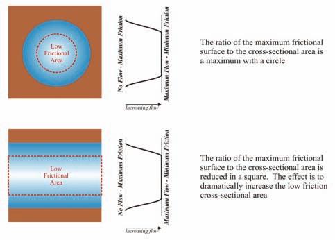
Figure 7. Schematic diagram to compare friction effects of a tube of set diameter compared to a plane of surface of equal diameter.
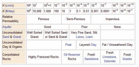
Figure 8. Hydraulic conductivity through different naturally occurring materials. (from:
Hydraulic_conductivity, original reference: Bird, 1972).
(...Continued from page 24)
consider the friction of the system. Features within the rock that reduce the friction of the system enhance the permeability of the system. This is an important concept when discussing fractures. When considering friction it is necessary to describe the source of the friction. The friction comes at the edge of the permeability pathway at the rock/fluid interface (Figure 8). At this boundary the flow is essentially zero, much like the flow at the base of a river channel is zero at the channel bottom / water interface.
Darcy’s law was based on observations of fluid through sand where the pore-to-pore connections are approximated by tubes, which are circular in cross-section. Fracture systems
are planar in nature and as such have a significantly different circumference-to-area ratio in cross-section as compared to pipelines. The result is a significant reduction in friction and enhanced flow along fractures compared to flow through an unfractured rock.
Another concept of fractures as a permeability enhancement is the length of the fluid pathway is reduced. In an unfractured rock the fluid must pass from pore to pore along a crooked, tortuous path. Fractures tend to be planar and, as such, straighten the path reducing the distance and enhancing the permeability of the system.
The effects of friction are not only felt by the shape of the cross-sectional area but also by the roughness of the surface. Fractures tend to have a smoother surface than a typical pore found within a rock. As such, the friction is further diminished by the smoothness of the fracture as well. The type of material plays a role in the friction between the fluid and the rock. Soil scientists have recognized this phenomenon and don’t discuss the permeability of a system, but rather hydraulic conductivity of a system (Figure 9 – Bear, 1972). This field of study has developed a series of empirical curves that take into account the soil lithologies as well as the conduit shapes.
The challenge that arises is to “Radial Drainage” and our base assumption that molecules closest to the well bore will drain early, whereas those far away arrive to the well bore later. But with the recognition of the fracture system as the principal fluid conduit is this assumption safe and are the reserve calculations based on radial drainage accurate?
REFERENCES
Bear, J. 1972. Hydrodynamic dispersion. In: Flow through porous media, R. J. M. DeWiest, (ed.). Academic Press, New York-London.
Bear, J. 1972. Dynamics of Fluids in Porous Media. Dover Publications.
Durham, L. S. 2010. Shale wells tend to be custom jobs. American Association of Petroleum Geologists, Explorer, December, p. 16.
Fabbro, G. 2010. Nuclear waste – A geologist’s perspective. http://www.science20.com/tuff_ guy/nuclear_waste_geologists_perspective.
Kreis, L. K., Costa, A. L., Osadetz, K. G. 2005. New perspectives on hydrocarbon potential of Bakken and Torquay formations, southeastern Saskatchewan. American Association of Petroleum Geologists, Annual Meeting Abstracts, v. 14, p. A75.
Johnson, M. S. 2009. Parshall Field, North Dakota – discovery of the year for the Rockies and beyond, American Association of Petroleum Geologists, Annual Meeting Abstracts, Denver, Colorado, June 7-10, 2009.
Morrison, M. L. and Cooper, M. 1992. The control of fracturing on reservoir quality and productivity within the Sukunka-Bullmoose play trend of the NE British Columbia foothills, American Association of Petroleum Geologists Annual Meeting Expanded Abstracts, v. 1992, p. 91-92.
Stearns, D. W. and Friedman, M. 1972. Reservoirs in fractured rock. In: Stratigraphic Oil and Gas Fields, R. E. King (ed.). American Association of Petroleum Geologists, Memoir 16, p. 82-106.
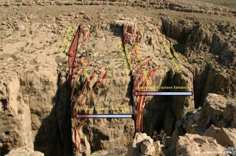
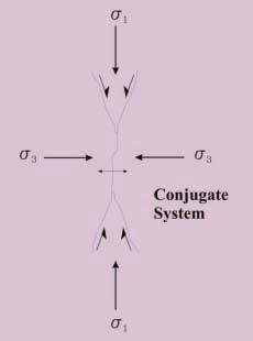
Figure 9. Conjugate fracture systems consist of two shear fracture surfaces acting with opposite senses of motion and a single extensional fracture oriented perpendicular to the minimum stress direction.
CANADIAN SOCIETY OF PETROLEUM GEOLOGISTS
Call for Nominations 2012 Executive Committee
In accordance with Article VI, subparagraph (a) of the By-Laws 2003, the Nominating Committee hereby calls for Nominations to Stand for Election to the 2012 Executive Committee of the Canadian Society of Petroleum Geologists.
Nominations can be made in two ways:
1) Formal Nominations are to be made in writing, signed by at least twentyfive members in good standing and endorsed by the nominee who is consenting to stand for office. Qualified candidates will be published on the CSPG website and the election will take place on January 10th, 2012 at the AGM.
2) Informal Nominations can be made via e-mail or letter; please confirm that the nominee is willing to stand for the office of choice and send to CSPG Office to the attention of the Past President. Candidates nominated in this fashion will be considered by the Nominations Committee.
The Canadian Society of Petroleum Geologists asks for your assistance in filling the following positions: Vice President, Communications Director, Assistant Director of Finance, Assistant Services Director, Assistant Program Director, and Assistant Outreach Director.
Interested parties should contact the office for details and general requirements of service on the Executive. Call for Nominations closes September 15th, 2011.
PARTNERSh IP T RAC kS AwARDS
The Partnership Tracks award is the CSPG’s newest award, having been created in late 2010. The award is to recognize non-CSPG members or non-geologists who have made outstanding contributions to the welfare and prestige of CSPG.
John Cuthbertson, Q.C., has been a volunteer Trustee of the Canadian Society of Petroleum Geologists Educational Trust Fund since 2000.
John’s commitment to the CSPG Educational Trust Fund has been exceptional over the last 11 years. He brings a straight-forward, non-geological approach, which allows us to groundtruth our decisions. His contributions to the Trust are invaluable due to the very broad range of experiences that he has had over his career. Although John is not a geologist and is not a member of our Society, he has selflessly volunteered his time, energy, and enthusiasm to make the CSPG Educational Trust Fund strong and vibrant.
John grew up in Red Deer, Alberta and attended the University of Alberta for his undergraduate degrees, subsequently
travelling to the Maritimes to attend Dalhousie University, where he graduated in 1979 with a combined MBA and LLB. John is a partner at Burnet, Duckworth & Palmer LLP (BD&P), where he practices in the Energy area and leads the Energy Group. He has received significant professional recognition for his contributions to the energy law sector. In addition, John has been very involved in the larger community. Most notable has been John’s involvement as a volunteer
GeoEdges Inc.
with Calgary Legal Guidance, where he has volunteered for over 30 years, including roles as Director and Board Chair. John was also a founding director for Pro Bono Law Alberta and is a past Governor of the Calgary Petroleum Club. John was a recipient of the 2004 Weldon Award from Dalhousie University for Outstanding Contributions to the Community and the Legal Profession, as well as a recipient of the Distinguished Service Award from the Law Society of Alberta and Canadian Bar Association for Service to the Community in 2000.
Annette Milbradt , a geophysicist and member of the Canadian Society of Exploration Geophysicists (CSEG), has made substantial contributions to the CSPG through her work with the Honourary Address committee, Kids in Science Program (KISP), and – most recently – Earth Science for Society (ESfS).
Annette was one of the champions of the ESfS Exhibition, an overwhelmingly successful outreach event, held at the GeoCanada 2010 convention. She worked with the past organizing committee members to expand on the Kids in Science Program, evolving it
Western Canada: Slave Point, Swan Hills, Leduc, Grosmont, Jean Marie, Horn River Shales, Elkton, Shunda, Pekisko, Banff, Mississippian subcrops and anhydrite barriers in SE Sask., Bakken, Three Forks, Montney, Halfway, Charlie Lake, Rock Creek, Shaunavon, BQ/Gething, Bluesky, Glauconitic, Lloyd, Sparky, Colony, Viking, Cardium, Horseshoe Canyon and Mannville CBM, Oilsands Areas, Outcrops
US Rockies & Williston: Red River, Mississippian subcrops & anhydrite barriers (Bluell, Sherwood, Rival, etc), Bakken, Three Forks, Cutbank, Sunburst, Tyler, Heath, Muddy, Dakota, Sussex, Shannon, Parkman, Almond, Lewis, Frontier, Niobrara, Mesaverde shorelines, Minnelusa, Gothic, Hovenweep, Ismay, Desert Creek, Field Outlines, Outcrops
North American Shales: Shale plays characterized by O&G fields, formation limit, outcrop, subcrop, structure, isopach, maturity, stratigraphic cross-sections. Includes: Marcellus, Rhinestreet, Huron, New Albany, Antrim, Utica-Collingwood, Barnett, Eagleford, Niobrara, Gothic, Hovenweep, Mowry, Bakken, Three Forks, Monterey, Montney, Horn River, Colorado
into ESfS. ESfS was Annette’s passion and she stepped up when needed to become Chair of the Organizing Committee, she managed Logistics and Exhibits and helped immensely with fundraising. Annette did not intend to get so heavily involved, however, she stepped up several times to work on the various necessary tasks needed to create the successful event that ESfS was. Around 2,000 Calgary area students, 500 members of the public, and 500 delegates were treated to 27 exhibits in 5 pavilions. Annette worked tirelessly; many volunteers noticed e-mails coming from her at very late hours of the night – e-mails sent to ensure that efforts continued in a timely manner. She was present, working enthusiastically throughout the event to ensure its success. During all of this, Annette also managed successfully to work hard at her position as a geophysicist at Tourmaline Oil Corp.
Annette managed her core of volunteers very well, with a combination of directness and friendly help that she is known for in the CSEG and CSEG Foundation. There was an overall volunteer effort of 100 people and 27 exhibits from across Canada. Volunteers were from several different companies and universities, and involved geologists, geophysicists, engineers, and university students. In fact, the Earth Science for Society Exhibition was so successful last year that it is was done again for the recovery 2011 convention.
In addition to Annette’s efforts with ESfS, she has worked on the Honourary Address Committee (sponsored by the CSPG, CSEG, and APEGGA), past Kids in Science Programs at conventions, and at countless local and western Canadian career fairs distributing CSPG and CSEG information and handouts.
The full Partnership Tracks award citations appear in the March 2011 issue of the CSPG Bulletin of Canadian Petroleum Geology.
Annette Milbradt
The Tournament would like to thank the following 2010 sponsors:
Diamond Sponsors
geoLOGIC Systems
Schlumberger of Canada Little Rock Document Services
Emerald Sponsors
GeoStrata Resources Inc.
IHS Energy
Macquarie Tristone Capital Advisors
Platinum Sponsors
AGAT Laboratories
Athabasca Oil Sands Corp.
Baker Atlas Wireline
Belloy Petroleum Consulting
CB Securities
Divestco Inc.
Energy Navigator Inc.
Fugro Data Solutions Canada Inc.
GLJ Petroleum Consultants
Halliburton
Gold Sponsors
Arcis Corporation
ATB Financial
ConocoPhillips Canada
Continental Laboratories Ltd.
Deepwell Energy Services
Devon Canada Corporation
Knowledge Energy Inc.
MD Totco Nov. Wellsite Gas Watch
Silver Sponsors
Barry Rypien
Gabel Energy Inc.
Martin Quinn
Bronze Sponsors
Candian Stratigraphic Services
Crow River Resources
RBC Dominion Securities
Weatherford Canada Partnership
Wildcat Scouting Services (1991) Ltd.
M J Systems
Painted Pony Petroleum Corp.
Pason Systems Corp.
ProGeo Consultants
RECON Petrotechnologies Ltd.
RPS Energy
Ryan Energy Technologies
Sproule Associates Ltd.
West Canadian
Pajak Engineering Ltd.
Petrocraft Products Ltd.
Polaris Resources Ltd.
Regent Resources Ltd.
ReSurge Ltd.
Rigsat Communications
Sample Pro Ltd.
Van Helden Agencies Ltd.
Montane Resources Ltd.
Trivision Geosystems
Hydro-Fax Resources Ltd.
San Dago Resources Ltd.
The CSPG Classic Golf Tournament has incorporated fundraising for charity as part of the event. In 2011,, the charities selected are the Salvation Army Agape Hospice and the CSPG Education Trust Fund. ,
NAME:
SPOUSE’S NAME: COMPANY:
ADDRESS (Bus.):
Registration Form
POSTAL CODE:
TELEPHONE: CELL PHONE:
E-Mail:
All contestants are required to have a photo in the Golfer’s Photo Roster. Former contestants who have submitted a photo in the past need not do so again. Handicap / Golf Index __________________ or Average of best three 18-hole scores in past 2 years:______________
Registration Fee: Includes three rounds of golf with power cart; Paid driving range; Door prize draws; Skill prizes; BBQ (at Elbow Springs) and Awards Banquet (Calgary Petroleum Club) both for you and your guest.
Cost: Tournament Fee $428.50 GST $21.45
Total if paying by cheque $449.95
To assist the Entertainment Committee with budgeting, please indicate if you plan to attend the two major social events of the tournament:
Wednesday Barbecue: Self: Yes q No q Guest: Yes q No q
Friday Awards Banquet: Self: Yes q No q Guest: Yes q No q
Social Events Cancellation or Additions require 72 hours notice before the event. Please contact Bob Earle by phone: (403) 803-3744 or email: cspgclassicgolf@gmail.com
* Please photocopy your entry form and cheque before mailing.
Last day for refund requests: June 1, 2011.
Mail/Courier Registration: Print this registration Form (http://www.cspg.org/events/events-social-classicgolf.cfm) send to CSPG Office with cheque.
DONATING PUBL ICLY TRADED SECURITIES
A great way to minimize taxes while supporting the CSPG Educational Trust Fund
| By Krysta L. Adamski, CA, Senior Tax Manager, WBLI Chartered Accountants, Bedford, NS, with Alberta rates updated by N. Calvin Stewart, CA, TEP of Kenway Mack Slusarchuk Stewart LLP Chartered Accountants
An often under-utilized tax planning strategy, possibly because it is not understood by many, is the donation of publicly traded securities. A gift of publicly traded securities is a very effective way to give to the CSPG Educational Trust. The tax treatment to the individual is favourable, and the CSPG Educational Trust can decide whether to hold or sell the security.
When you dispose of securities, you must pay tax on 50% of the capital gain (fair market value at the time of transfer, less adjusted cost base, which is usually your original cost). Effective May 1, 2006, when you donate publicly traded securities, the capital gain, that would otherwise be taxable, is not included in income. This means that there is no tax to the individual on the transfer to the CSPG Educational Trust and the individual receives a donation tax receipt for the full value of the security at the time of transfer, which can be claimed on the individual’s personal tax return.
If you hold publicly traded securities that have increased in value since you purchased
them, and you are considering making a donation to the CSPG Educational Trust, you should look at donating those securities instead of selling the security and donating the net cash proceeds. For example, if you have a security worth $10,000, which you originally purchased for $2,000, and you were to sell this security, assuming a tax rate of 39% (Alberta), you would pay tax on the sale of approximately $1,560, being $8,000 x 50% taxable x 39% tax rate. You would be left with $8,440 to donate to the CSPG Educational Trust, which would result in a tax credit of $4,220, being 50% on donations in excess of $200. This will offset your taxes on the capital gain of $1,560, leaving you with a credit of $2,660 to be used against taxes on other income.
Instead, if you were to donate the security to the CSPG Educational Trust, your taxes on the transfer would be eliminated, giving you a donation receipt for the full $10,000 value of the security, which would result in a tax credit of $5,000 representing additional tax savings of $2,340, being a $2,660 net credit vs. a $5,000 net credit. The tax rates will vary
CSPG Trust
Geoscientists for our future
depending upon your province of residence.
In order to use a donation to reduce your current year taxes, it must be received by the CSPG Educational Trust by December 31st. If you cannot use all of the donation tax credit in the current year, you can carry it forward for five years. You can make a difference by funding the CSPG Educational Trust you care about while also helping to minimize your own personal taxes.
Kenway Mack Slusarchuk Stewart LLP offers a full range of accounting, tax and business advisory services to clients in the Calgary and Bow Valley corridor. For more information please visit our website at www.kmss.ca 220, 333-11th Avenue SW, Calgary, AB T2R 1L9 Telephone: 403-233-7750, Fax: 403-266-5267
FIVE THINGS that you can do in 2011!
Looking for new ways to support the next generation of geoscientists? Here are a few ideas! Consider building these into your goals for 2011.
1) Recognize the accomplishments of others.
The CSPG and the CSPG Educational Trust Fund have awards that are used to recognize outstanding achievement, excellence, and the accomplishments of many individuals in the geosciences, from students to teachers to stalwarts in the world who have made a difference. We can set up specific awards, at your request, to your liking.
2) Promote knowledge
Support publications, be they online or on paper. The Bulletin, the Reservoir, mapping projects, and a Digital Atlas, are just a few examples of worthy works of art and science that need to be converted into the digital realm. Endow to webcast all of the convention / divisional talks to CSPG members and / or the public. Support your University with an endowed subscription to all CSPG publications to provide perpetual
access to staff and students or with Grants in Aid to support research at the graduate student level. CSPG also makes available many special publications each year as well. You can also support SIFT (students could win scholarships for SIFT mapping game success), Earth Science for Society, continuing education, undergraduate thesis awards, visiting lecturer tours (expand to include career opportunities) to universities across Canada, scholarships, K-12 programs (including Career fairs and events), and internet services that are vital to disseminating scientific information. Support an annual lecture on a specific topic at annual CSPG events, be they the convention, Honorary Address, Technical or Division lunches, or at Social events.
3) Build the Future
Many proposals are submitted to the Trust on a yearly basis t hat are in need of funding. Some are research oriented; some are for field work, teaching, or training. Your contributions enable more geoscientists and students to reach their objectives. Have something specific in mind? You may want to support a specific program, or you
WAYS TO CONTRIBUTE
Contributions may be made in several forms. Consider which method gives you the greatest tax benefit, as provided under Canadian Tax / CRA rules.
• Gifts of cash
• Gifts of publicly traded or private corporation securities
• Gifts of naming the CSPG Educational Trust Fund in your will or Trust
• Gifts of directed funds to your specific legacy goal
• Gifts of life insurance, annuities, retirement plan assets, or real property
At your option, specific gift designations can be made:
• For a specific fund
• In memory or in honour of a special person, friend, relative, professor, or colleague. We would be glad to notify the person or their family and friends that you want recognized of your contribution.
We would be glad to provide information to help you choose the best way to contribute. Please feel free to call or write us with any questions. You can also request
Geoscientists for our future
may choose to provide financial assistance for college and university professors to help defray the cost of attending CSPG courses or recognize high achievement amongst geosciences faculty members. Help expand student initiatives at the annual convention, provide CSPG book store gift certificates to student presenters, or support field school programs that are under increasing funding pressure. We will design to fit your legacy desire.
4) Remember someone
Make a contribution to any of the wonderful programs that the CSPG Educational Trust Fund supports, and do so in Honour of or in Memory of a special individual or loved one. We’ll be sure to give them the recognition that they deserve. These can be restricted or unrestricted funds to further the mission of the Educational Trust Fund.
5) Get involved
Your presence is requested!
The investment of your time gives us access to your experience and enthusiasm.
CSPG Trust
Geoscientists for our future
that your donation remain anonymous, should you so choose.
The CSPG Educational Trust Fund is currently recruiting board members to fill vacant seats.
If you have experience raising funds for charitable organizations, we would like to talk to you about our goals! Help us by volunteering your time, please contact us at cspgtrust@cspg.org
LEGACY SOCIETY of the Educational Trust Fund of the CSPG
The Trust’s Legacy Society was established in 2011 by the Trustees of the CSPG Educational Trust Fund to honour and recognize donors who have advised the Trust of the creation of a legacy gift to the Trust through their estate plans.
The Trustees of the Trust honour and recognize these generous donors who have chosen to leave a legacy that will assure program support in future generations:
DonATIon S ovER $2000
Robert Dick
Claus Sitzler
Bellport Resources
DonATIon S $1000 - $2000
Michael Hriskevich
Tako Koning
Keith Lowell
Paul Price
Peter E. Putnam
Sayer Securites
DonATIon S $250 - $1000
Rein De Wit
Michael DeRoches
Jon Dudley
Thomas Gallagher
Bill Aryton SIFT
Family of Andy Baillie Andrew D. Baillie Award
If you are committed to suppport the CSPG Educational Trust Fund’s mission through a bequest or other planned gift, and desire to be included in the Legacy Society, please notify us so that it can be mentioned in next year’s report.
The Trust can put you in touch with professionals at the Calgary Foundation that can assist you in the different options that are available in leaving a legacy and properly setting up that gift.
W. Gamp
Gordon Holland
James Kirker
Ian Kirkland
Charles Stelck
Brenda Wright
DonATIon S $100 -$250
John Ambler
John M. Andrichuk
Philip R. Brown
Nancy Chow
James Christopher
Donald Cook
Wilbert Danner
John A. Downing
Robert Earle
Robert H. Erickson
Earl Fawcett
Michael Fawcett
Andrew Fox
Murray Frame
Michael C. Frank
Paul Fuenning
R. Glaister
Len Hills
R.M. Jackson
Donald Kent
David Marchioni
D.K. Mclvor
David Middleton
Eric W. Mountjoy
Daryll W. Myhr
B.S. Norford
Godfrey Nowlan
Robert Orr
A. E. Pallister
Alice V. Payne
Ronald Piatt
Ken Potma
Mohammad Sabir
Moh Sahota
Scott Smith
B.K. Smith
Roy E. Smith
David Smith
Donald F. Stott
Ferdl Taxbock
Dr. Christian Viau
Gordon D. Williams
Richard Willott
Dr. Raymond Yole
Cenovus Energy
(Continued on page 32...)
DonATIon S
uP To $100
Gary Addison
Sandeep Alexander
Howard Allen
Norbert Alwast
John Andersen
Kelvin Anderson
Lynn AndersonBruce
Larry Annand
George Ardies
Peter Aukes
Roger Baines
Christopher Baldwin
Larry Barkley
Brad Barrie
Paul Batson
Michael Beattie
Michel Beaulne
Michael Bell
Daniel Bernst
Michael Blair
Graeme Bloy
Kaley Bosch
Greg Bourassa
K. Bradley
Rotiald Bray
Charles Brehon
J. R. Brook
Laurie Brough
Robert Brown
John Bryce
Stephen Burnie
E. Matthew Caddel
Anthony Cadrin
Finley Campbell
Brian Carrigy
Craig Cartier
Neil Cathcart
Alejandro Chalco
Burns Cheadle
Dongqing Chen
Youyi Cheng
Guoxiang Chi
John Chipperfield
Curtis Chmilar
Andre Chow
Leonard Chow
Magda Ciulavu
Richard Coates
David Collar
Debbie Cook
Richard Cooper
Norman Corbett
Gerald Costigan
W.C. Cox
G. A. Sandy Crawford
Stephen Creaney
Gordon Crooks
Robert Cruickshank
Brad Curtis
Brian Curts
Nathan Dahlby
John Davey
S. Richard Davis
Brian Dean
Meridee Fockler
Brian Fong
Brad Ford
Riona Freeman
Colin Frostad
Jenny Fu
Terry Fullerton
David Gardner
Douglas Gardner
William Gatenby
Michael Geier
James Genereux
Robert Gerhardt
Santosh Ghosh
Kevin Gibson
Peter Goetz
Julius den Haan
Ian DeWolfe
Jeffrey Dickson
Diane Diebel
James Dixon
Kathleen Dixon
Steven Dixon
D. James Doig
Kenton Donaldson
Justina Maria Donkers
Oscar Gonzalez
C. Arnold Gorveatt
Jack Gould
David Grawbarger
Darcie Greggs
Lisa Griffith
Murray Gunn
Charles Gusa
Jeff Gysler
Antoine Habib
Stephen Halabura
Get More from your Core
With reservoirs becoming increasingly complex, you need the information you can get better understand reservoir.
Weatherford helps you more from core combining an unsurpassed global team geoscientists, engineers, technicians and researchers with the industry’s most comprehensive, integrated laboratory services worldwide. From core analysis, sorption, geochemistry and isotopic composition to detailed basin modeling and comprehensive data packages, we provide you with real reservoir rock and fluid information that hasn’t been distilled by a simulator or iterated by software.
We call it “The Ground Truth™” – giving you the accurate answers you need for better reservoir understanding. You’ll call it a better return on your reservoir investment. To learn more, contact TheGroundTruth@weatherfordlabs.com.
Mary Downey
Michael Downey
Calin Dragoie
Kenneth Drummond
Stephen Dryer
Roger Dueck
David Dukes
Kyle Durocher
Andrew Edmunds
Sydney Edwards
Vincent Ekvall
Douglas Ellenor
Kenneth Ellison
Stephen English
David Erickson
Olajide Esho
Mel Estoque
Tristan Euzen
Andrew Evans
Ken Fast
Eric Fauveau
Mark Fenton
Peter Fermor
Christopher Fic
C. Mike Finn
Brian Fischer
Robert Fisher
Robert Flowerday
John D. Harper
Joe Harris
David Harris
J.R. Harris
Travis Hauger
Roderick Haverslew
Michelle Hawke
E. Hawkes
Peter Hawkes
Simon Haynes
Adam Hedinger
Andrea Henry
Brian Hester
Thomas Hewitt
Kevin Hicks
Alan Higgins
Debra HigleyFeldman
Victor Hill
Georgia Hoffman
Andrea Hood
Mary Horan
Garry Howard
Roger Hume
Dave Hutchinson
Tim Hyde
Wim Jalink
Patricia Jans
Al Jenik
Gary Johannson
David Johnston
Greg Jones
Rene Jonk
Cecil Keeping
Garry Kelman
Joyce Kennedy
Reid Kennedy
Kim Kingsmith
Kelly Kingsmith
Tyler Klatt
Louise KlatzelMudry
John Koning
Alec Kovaltchouk
Doug Kozak
Andrew Kramchynski
L. Kim Kreis
Rick Kunimoto
Robert Langill
Francois Langlois
Matthew Law
Peter Laws
Robert Lee
Vincent Lefebvre
S.R. (Sid) Leggett
Robert Leonhardt
Paul Levesque
Gregg Little
Wendy Lomnes
Grant Los
Gregory Lynch
Daniel MacDonald
Gerald Macey
Duncan MacFarlane
Robert MacFarlane
A. Howard MacKay
Marlene Mackay
Janet MacKenzie
Rory MacKenzie
John MacRae
Brian Mahood
Lynne Maillet
Charlene Maines
Ron Mak
Roman Makar
Heather Makowecki
Robin Mann
L.S. Manz
J. Mathison
Blair Mattison
John Mawdsley
David May
Duncan Mccowan
David McDonald
Debra McDonald
Michael McDonough
Monica Meding
John Meloche
Bruce Miller
Douglas Minken
Ronald M. Misko
Ian Moffat
Dorel Mogosanu
Peter Moignard
Tim Montgomery
Jason Montpetit
Harry Morris
Kevin Morrison
David Morrow
Frank Muller
Kevin Mutterback
Thomas Nardin
Marilyn Neary
Shona Ness
Andrea Newman
Hammond Nicolle
Greg Niebergall
Olga Nielsen
James Noval
Egide Nzojibwami
Douglas Oicle
Mark Oliver
M. Elizabeth O’Neill
Gerard O’Reilly
John Ostrom
Bianca Palosanu
Vittorio Panei
Greg Pavan
S. George Pemberton
Amanda Perrot
Steven W. Perry
Lucy Perry
Therese Pettigrew
Peter Philipchuk
Peter Phillips
Leo Piedimonte
Christopher Pike
Christopher Podetz
Denise Poley
Sharlene Pollock
Judith Potter
Michael Powell
Wayne Pridham
Jake Pronk
John Pruit
Mitchell Putnam
Samuel Quantz
Mohsen Ragheb
Donald Rawlyk
Fred Rayer
Marcia Rempe
Peter Richards
Sue Riddell
Rose
David Robinson
Michael Robinson
Drue Robinson
Richard Rouble
Phillip Roulston
Thomas Ruissen
Neil Rutherford
Lisa Sack
Javier Salam
Peter Saltman
David Sandy
Toshiaki Sato
E. Schink
David Scott
Gary Shaner
Kenneth Shaw
Valerie Shaw
Darrell Shaw
D. Shedden
Dean Sheppard
Mike Sherwin
Bruce Shultz
Leigh Skinner
Catherine Skulski
Warren Smart
Leigh Smith
Richard Smith
Mick Somerwil
David Stelck
Chris Steudler
Patrick Stevenson
Rudy Strobl
Oleh Stupnyckyj
Gerald Sullivan
Shane Sutherland
Alan Tambosso
Mark Teare
Craig Terry
Jean-Louis Teurlai
David Thomas
G. Thompson
Jason Thompson
John Thorpe
Clinton Tippett
Kenneth Tompson
Vladimir Torres Hernandes
Gordon Trainor
Catherine Troke
Fred Turner
Uldis Upitis
Victor Urban
Sandra Vanden Brink
Michael Veloski
Victor Verkhogliad
Herbert Visscher
Daniela Vlad
Hans Von Der Dick
Garry Wasylycia
Edmund Watchuk
Michael Watson
Ken Weaving
Gordon Webb
Shawna WeirMurphy
David Weiss
John Weissenberger
Gordon Wells
Charles Welsh
James Welykochy
Lawrence West
Jonathan White
Geoff Wilcox
Andrew Williams
Samuel Wilson
Robert Workum
Oleh Wowkodaw
Andrew Wray
Dale Wright
Heather Wright
Peter Wuntke
Gerald C. Yamada
Donald Yont
Michael Zander
Leonard Zarka
James Zhang
John Zhao
DonATIon S uP To $50
Please see the Trust website at www. cspg.org/trust/ trust.cfm for a list of all donors.
We would like to thank our anonymous donors as well
www.cspg.org
Canadian Society of Petroleum Geologists
22nd ANNUAL MIXED GOLF TOURNAMENT
FRIDAY, AUGUST 26, 2011 - LYNX RIDGE GOLF CLUB
Format: Modified Texas Scramble , shotgun start at 8:00 am. Teams will be assigned according to handicap or average score This is a fun tournament open to both men and women Registration includes a Continental Breakfast, Dinner, Green Fees and Power Car ts.
Registration Deadline August 5, 2011 (Priority will be given to CSPG Members). CSPG Members: Register online at http://www.cspg.org/events/events-social-golf.cfm. Non-Members and Guests: Mail or fax your form to CSPG’s office (contact information below).
CSPG - Member # Non Member
Name:
Company:
Address:
Phone (daytime):
Email:
Male Female
Phone / Cell (evening):
Club Handicap or average 18 hole score:
Guest Name: (One guest allowed per CSPG Member)
Male Female
Club Handicap or average 18 hole score:
Please note: A Waiver must be signed by EACH par ticipant 5 business days prior to the Mixed Golf Tournament A waiver form will be distributed to you once your registration form has been processed If a waiver is not signed prior to the tournament, your registration will be removed from the tournament. All registrations must be accompanied by full payment. All Cancellations or Amendments to registrations must be received in writing via email to Brenda Pearson at bpearson@birchcliffenerg y.com. Phone requests will not be accepted The Cancellation or Amendment must be received by 4:00 pm on August 12, 2011. A 15% Cancellation and Administration fee will apply.
For more information, contact Brenda Pearson at 403-206-3339 or David Caldwell at 403-852-5571.
$ 90.00 Member
$ 130.00 Non-Member / Guest
ying guests Maximum 10 spots; first-come , first served.)
GST # 118836295)
Expiry:
Signature:
Canadian Society of Petroleum Geologists
Attn: Mixed Golf Tournament
600, 640 – 8 Avenue SW Calgary, Alberta T2P 1G7
Phone: 403.264.5610 Fax: 403.264.5898
Photos are taken during the tournament and are sometimes used for promotional purposes in CSPG publications. Your consent is needed to publish a photo where you are identi able in the picture. Please contact our o ce if you do not consent to your photo being used for promotional purposes
CSPG GRADUATE STUDENT Thesis Awards – 2010
The Graduate Student Thesis Awards was first presented in 1958 with one combined M.Sc. / Ph.D. award for the first several years. Since 1964 the award was separated into its present format of a separate Ph.D. and M.Sc. thesis award. Over the past 52 years, the winners of this award have included some very well-known geologists. A complete list of winners is on the CSPG website (www.cspg.org/ awards/students/graduate-thesis.cfm). The award has changed little since its inception, with the selection criteria being that the eligible thesis be completed at a Canadian university, regardless of project location or that the thesis deals with a Canadian sedimentary / petroleum geology topic, regardless of university location. The major change over the years has been the monetary reward for the winners. The first winner of the award, Robert G. McCrossan, received $200 from the then ASPG. In the mid-1980s the award was increased to $500 for the Ph.D. winner and $300 for the M.Sc. winner. Since 2005, the Ph.D. winner receives $2,500 and the M.Sc. winner receives $2,000.
The winner of the 2010 M.Sc. award is Jennifer A. Boutelier (née Macauley) (University of Toronto, Prof. Sandy Cruden, supervisor –currently at Monash University, Australia) for her thesis “Timing and Mechanisms Controlling Diapirism on Ellef Ringnes Island, Canadian Arctic Archipelago”. Her thesis is a well-written, detailed, multi-disciplinary study of the development and evolution of evaporite piercement structures in the Sverdrup Basin.
The Sverdrup Basin has since the 1950s intrigued exploration geologists for its oil and gas potential. Numerous studies and periodic exploration has taken place to try to unravel the resource potential of the basin. MacAuley’s thesis examines an area with spectacular evaporite structures and studies the timing and mechanisms involved in the initiation and formation of evaporite structures.
Macauley’s study successfully integrates geophysical and structural modelling to address salt movement over time in a tectonostratigraphic context. Review of
previous work, analysis of the existing wellbore and 2D seismic data, backstrip modelling on the well data, and analogue modelling formed the core components of her thesis.
Jennifer A. Boutelier (née Macauley)
Your Wellbore Solution.
Reservoir Engineering
The thoroughness of the research, and the completeness of the presentation are strong aspects of this thesis. The thesis is concisely presented, well written and illustrated, and has a practical approach. The discussion on petroleum generation and potential for future oil and gas exploration, along with the future recommendations, brings the study in focus for the petroleum exploration geologist. This study should be of interest to CSPG members working in the Sverdrup Basin or in other basins where evaporite piercement structures are an important aspect of petroleum exploration.
After careful consideration, it was decided not to give out the Ph.D. award for 2010, in part, due to the low number of entries.
A project that the committee undertook this year has been to update the list of winners to include their thesis topic, university and supervisor. The database is now complete back to the mid-1980s, although some data is still missing on pre-1986 winners. The current list is can be found at www.cspg. org/awards/students/graduate-thesis.cfm. In most cases, the missing data is either the university where the thesis was completed or the winner’s supervisor. If you can help fill in the blanks or notice any mistakes in the data please contact Andre Chow (andre.chow@ pengrowth.com). We are hoping to complete the list for the website in the near future.
GO FURTHER THAN PETROPHYSICS
Manage, edit, organize and analyze all your data together in one environment...
• Develop in the core domain and reconcile to the log domain, or optimize directly in the log domain
• Apply saved models and export to reservoir modeling software
• QC and analyze pressure-time pre-test data
• Detect uid types, free uid levels and hydraulic zones in single or multi-well pressure-depth analysis mode
Many thanks are extended to all the members of the committee for taking time out of their very busy schedules to evaluate this year’s theses. The committee members are Tim de Freitas, Richard Evoy, Tony Hamblin, Sid Leggett, Cindy Robinson, Terry Sami, Anne Sherman, Martin Teitz, Michael Webb, and Andrew Willis. The committee welcomed Anne and Cindy as new members of the committee this year. Their input has already proved to be valuable to the committee. Eileen Scott, who had been on the committee for several years, left the committee this year as a result of being transferred to Houston with her company. Her enthusiasm and insights will be missed. Also, thanks are extended Pengrowth Energy Corporation for their support.
The committee is always looking for members interested in reading and judging theses. Participation provides members with an opportunity to keep up to date with current university research. If you are interested in serving on next year’s committee, please contact Andre Chow or any of the other committee members for additional details.
2010 T RAC kS AwARDS
Tracks Awards are presented annually to CSPG Members who have made outstanding contributions to the Society through committee or other work. The award is designed to recognize individuals who have set new standards of excellence within the Society. The recipients of the 2010 awards are Denise Hodder and v ittorio ( v ic) Panei .
Denise Hodder is a long-serving volunteer member of the CSPG. Her earliest involvement was as a member of the Student Industry Field Trip (SIFT) Committee in 1996. She was SIFT Treasurer from 1996 to 1998 before becoming the committee Co-Chair later that year. Denise stepped back into the role of Treasurer in 2009 and has remained there until the present time. During that same period of time, she was also a member of the Honourary Address Committee (1996 to 2000) where she was responsible for bringing in well-known speakers such as palaeontologist Phil Currie and Bill Nye “The Science Guy” from PBS. Expanding out to the annual convention, Denise was the Co-Chair for the CSPG Conference Field Trip Committee in 2001. More recently, Denise has been a key member of the CSPG University Outreach Committee since 2005, with her main role being the coordinator for the Atlantic Canada Student Chapters. As a native Newfoundlander, she has worked very hard to raise the profile of the CSPG in the Atlantic Provinces, while at the same time reminding the CSPG of the importance of geoscientists from the Maritimes, and of the offshore reserves along Canada’s East Coast. One of Denise’s recent contributions is that she has designed a pamphlet that CSPG is using as part of our Outreach program. These are used to educate grade school children up to adult members of the general public about the CSPG and petroleum geology.
It was during the GeoCanada 2010 convention that Denise really went above the call of duty and set new boundaries for our volunteers. She almost single-handedly designed a CSPG booth for the Earth Science for Society (ESFS) section of the convention. She decided to focus on two aspects of the petroleum system: source and reservoir - not exactly easy concepts to introduce to over 2,000 junior high school students, their teachers, and parents! Denise designed many great interactive exhibits that allowed her and others to demonstrate aspects of petroleum geology simplistically
to an unfamiliar audience. Highlights were a huge mason jar full of organic ooze, a molecular stick model illustrating source rocks that generate hydrocarbons, a deltaic system made out of different coloured sands and gravels, an inflatable wading pool, and countless buckets of water, all of which thrilled and delighted the audience. She was able to generate a lot of discussion about depositional systems and how geologists use these models in our daily work. To top this off, she scheduled a rotating group of volunteers to assist her, and created “The Dummies Guide to the CSPG ESFS Booth” so that volunteers would understand the significance of each of the displays and how they related to the geological concepts they were trying to convey.
The work of volunteers like Denise Hodder is the reason that we are now planning to have an ESFS section at our future joint conventions. She is clearly passionate about her profession, and goes out of her way to share it and promote it with everyone around her.
v ic Panei has made outstanding contributions to the CSPG since 1975. He is probably best known for his dedicated service on the Photographic Committee, where he has served over the past 30 years. In fact, for many of those years Vic was the sole member of the committee. In his role as ‘CSPG Photographer’, Vic has spent countless hours helping to document the Society’s activities. He diligently took photos at CSPG social events, field trips in the Canadian Rockies, and Technical
Luncheons (from the days in the dungeons of Penley’s where lunch consisted of sausage and mash potatoes with an optional bottle of beer, through to the more luxurious setting of the Westin in the 1980s and 1990s, and up to the present location at the Telus Convention Centre).
Born and educated in Italy, Vic graduated in 1964 with an Honours Degree in Geological Sciences from the University of Rome. After serving his mandatory duties in the Italian Army, Vic immigrated to Canada in late 1966 and has been a Calgary resident working in the oil patch until his retirement in 2003.
From 1967 to 1969 Vic worked as a junior geologist at Canadian Pacific Oil and Gas. He then joined INEXCO as a junior geologist in 1970. From 1971 to 1981 he worked as junior to district geologist with Michigan Wisconsin Pipeline / American Natural Resources. In 1981, Vic joined AGIP Canada where he was Chief Geologist until 1988. He then joined Kerr McGee Canada as Senior Geologist and continued at Devon Canada through its acquisition of Kerr McGee Canada and Northstar Resources until his retirement in May of 2003.
Vic is a passionate outdoorsman: hiking, scrambling, snowshoeing, and cycling are his favourite activities, during which he practises his other lifetime passion – photography.
Full citations for the 2010 Tracks Awards appear in the March 2011 Bulletin of Canadian Petroleum Geology.
Denise Hodder
Vic Panei
GO TA kE A hIkE
Upper Kananaskis Lake, Kananaskis Country, Alberta
| By Philip Benham, Margot McMechan, and Yingchun Guan
Trailhead: Proceed 50km south of Trans-Canada Highway on Hwy 40, turn right on Kananaskis Lakes Trail. Drive 15km to Upper Lake parking lot (P).
Distance: ~16 km loop. Walk counterclockwise around the lake for best lighting of peaks. The trail around the lake is clearly marked. Maintained, but unpaved trail. Fall colours are spectacular.
Elevation Gain: 60m over the crest of the rockslide.
Upper Kananaskis Lake is one of series of waterways dammed to provide hydroelectric power to Calgary. The loop trail around the lake provides opportunity to observe Upper Paleozoic strata, some beautiful folds, and a large landslide. A series of small waterfalls grace the back end of the trail.
The Upper Devonian Palliser (limestone, dolostone, and bedded chert), the black shales of the Exshaw, the Mississippian Banff (bedded cherts, limestone, and black shale) and Livingstone Formations (light gray limestone and silty brown dolomite) are all exposed along the trail route. The younger strata of the Mount Head Formation (recessive silty brown dolomite, cherty limestone, and siltstone) can be seen capping some mountains such as Lyautey on the SW side of the lake. All this strata has been brought to the surface by the Bourgeau Thrust Fault. The fault has carried the rock tens of km northeastwards and compressed the hanging-wall into a series of folds. The fold axes are NNW-SSE oriented and are bisected by the lake, providing perfect view into the folds as one walks around the lake. The Bourgeau Thrust is one of the longest in the Canadian Rockies, extending from well north of Banff to near the US border.
At the north end of the lake, the trail will take you up and over the confusingly named Palliser Landslide (at the foot of Mount Indefatigable). Steeply inclined Livingstone limestone in the limb of the Sarrail Creek Syncline tends to slip at the contact with the shalier Banff Formation. Based on the weathering and variable lichen and tree growth, it appears that there were at least two major slides since the last Ice Age. The inclination of the beds and steep rock faces in the Livingstone suggest that more are likely in the future. The slide rubble allows observation of ripples, burrows, and marine invertebrates such as brachiopods and crinoids. Some of the older slide material exhibits karst features or differential weathering; look for closely spaced rills and weathered knife edges.
Reference: McMechan, M. E. 1998. GSC Map 1920A, Peter Lougheed Provincial Park. (Terrain map from http://maps.google.com)
by
Photo
Astrid Arts.
Bottom Left: View of folded Banff Fm in Warspite Anticline. Right: Cross-lake view of Mount Indefatigible with blocky carbonates of Livingstone sitting on “ribbed” Banff Fm with Exshaw and Palliser at base. Sarrail Creek Syncline runs parallel to mountain (axis defined by blue arrows).
The Reservoir Committee welcomes contributions from our readership to this series. If you wish to offer a submission to Go Take a Hike on your favourite hike of geological interest, e-mail the Reservoir or caitlin.young@cspg.org for more information.
of Mount Lyautey on western side of lake seen from near trailhead. The face of the mountain consists of the Palliser (PA), Banff (BF), and Livingstone (LV) Formations. It is capped by the recessive brownish siltstone and carbonates of the Mount Head Formation (MH).
View up Mount Indefatigible from a mid-slide position. Arrows point to landslide slip surfaces on steeply inclined beds. Slide blocks in foreground consist mostly of rippled and burrowed silty Livingstone carbonate.
View
Karst-like rills on fallen limestone block, Palliser landslide
Crinoids, brachiopods, and rip-up clasts (dotted line) in Upper Banff Formation.
Nodular to bedded chert and limestone of the Palliser Formation on backside of Mount Indefatigable.
GO TA kE A hIkE
Plain of the Six Glaciers, Banff National Park, Alberta
| By Philip Benham, Yingchun Guan, and Jeremy Anderson
Trailhead: Proceed from the parking lot of Chateau Lake Louise. Follow the well maintained walking path along the north side of lake where it ascends in switchbacks to the teahouse. The trail continues to a final view of Mt Lefroy.
Distance: 14.8 km return with about 340m elevation gain. For some, the teahouse, about 1.3 km from end of trail, is an acceptable end point of this long hike. Trail is heavily used but well maintained. One part of the trail on a steep slope has a cable handrail.
This popular hiking trail provides one of the more scenic settings in the Rockies. Quickly escape the swarms of tourists who go no further than the manicured patio of Chateau Lake Louise and enjoy the changing views along the north side of the lake and up into the Plain of the Six Glaciers. Warm up with a cup of tea or a light snack at the Teahouse, a welcome reward for your efforts on this hike.
The sculpted peaks around you consist almost entirely of the Gog Group. The Gog is a Lower Cambrian, shallow-shelf deposit of pinkish to grey quartzite and quartzose sandstone, with minor siltstone and shale. It is largely inaccessible to close perusal until you reach the SW corner of Lake Louise. Here, steep outcrops provide opportunities for roped climbers to observe the abundant crossbeds, and also for curious geologists to observe the abundant crossbeds and occasional trace fossils. The Gog and the Precambrian Miette Group (poorly exposed at the start of the hike) form a thick siliciclastic wedge upon which the Cambrian Carbonate platform ultimately developed. The Gog is present along the length of the Canadian Rockies, but it consistently shales out westwards. It also exhibits cyclic deposition of thick sandstones and thinly bedded sandstone, siltstone, and shale. The Gog contains locally abundant trace fossils, including Cruziana (trilobite crawling marks), Bergaueria (anenome living impressions), and Skolithos (vertical tubes created by worms). In some places Skolithos is so abundant in the coarser sandstones that it is referred to as “pipestone” rock.
The mountains surrounding the plain contain six glaciers, though not all are visible from the various viewpoints. The most visible are the thin tongues of ice that rest on either side of Mount Lefroy. While the glaciers today are small, evidence of their awesome power is evident in the huge lateral moraines than run along the edge of the valley. The last leg of your hike is atop one of the moraines. The extent of the ice is partially masked by extensive rockfall. Have a look for large fractures in the ice (crevasses), which form as the ice flows over the ground surface.
REFEREnCES: GSC Maps 1482A and 1483A.; Merino, E., Canals, A., and Fletcher R. 2008. Geologica Acta, v. 4, no. 3, p. 383-393.; Hein, F.J. and McMechan, M.E. 1994. Chapter 6 in the Geological Atlas of the Western Canada Sedimentary Basin, Mossop and Shetsen (comp.), www.ags.gov.ab.ca/publications/ wcsb_atlas/a_ch06/ch.html.
by
Photo
Above: Commanding view near start of trail with glaciers perched atop Mt Victoria. Right: Fairview Mountain (S. side of Lake Louise) displays packages of thick sandstones and thin sandstones interbedded with fine-grained sediments. This cyclicity is common in the Gog
LefroyGlacier
View of Cambrian formations exposed on slopes of Mount Lefroy (GG=Gog, MW=Mount Whyte, CA=Cathedral, ST=Stephen, EL=Eldon). White arrows point to large lateral moraines. Mount Huber and Lefroy straddle the continental divide and the provincial border runs along their crests.
Close-up of a boulder of Gog Group sandstones. Note the abundant cross-bedding formed in a high energy setting.
Near the end of the trail boulders of Cathedral Formation carbonates litter the slope. This boulder exhibits unusual patterns known as Zebra stripe dolomite, which are thought to be displacive veins that grew during the deformation of the rock (Merino et al, 2006).
View of the spectacular, glacially incised wall of Gog at the base of Mount Lefroy (foreground). The greenish gray shale, siltstone, and limestone of the thin Mount Whyte Fm are difficult to pick up from a distance, but can be observed in rockfall along the trail. Mt. Lefroy was apparently named in 1884 by G.M. Dawson, who honoured astronomer / meteorologist General John Lefroy. The nearby Abbot climbing hut honours Philip Abbot, who became the first climbing fatality in the Rockies while attempting to ascend Mt. Lefroy in 1895. One year later a memorial climb led by Prof. Charles Fay was successful in reaching the summit. The narrow gorge from which the Victoria Glacier issues is known as the “death trap.”
The trail begins ascending towards teahouse, past thick, rhythmic-bedded Gog at the foot of Mount Whyte.
Victoria Glacier
Office of Publication: Canadian Society of Petroleum Geologists 600, 640 - 8th Avenue SW, Calgary, Alberta, Canada T2P1G7
T2P 1G7 40070050
Canadian Publications Mail Product Sales Agreement No. 40070050 Return postage guaranteed.
CONTENTS
D.I. JOHNSTON, C.M. HENDERSON and M.J. SCHMIDT
Upper Devonian to Lower Mississippian conodont biostratigraphy of uppermost Wabamun Group and Palliser Formation to lowermost Banff and Lodgepole formations, southern Alberta and southeastern British Columbia, Canada: Implications for correlations and sequence stratigraphy
A. KHIDIR and O. CATUNEANU
Diagenesis of the Cretaceous-Tertiary Willow Creek sandstones, southwestern region of Alberta
K. AZMYand J. CONLIFFE
Dolomitization of the lower St. George Group on the Northern Peninsula in western Newfoundland: implications for lateral distribution of porosity
D.M. PETTY
Sequence stratigraphy and sequence boundary characteristics for upper Tournaisian (Mississippian) strata in the greater Williston basin area: an analysis of a third-order cratonic carbonate-evaporite depositional cycle
Stratigraphyand sedimentary environments of the Lower Cambrian Gog Group in the southern Rocky Mountains of Western Canada: Transgressive sandstones on a broad continental margin
www.cspg.org
To view the current issue of the Bulletin, please visit www.cspg.org/eseries/source/security/site-logon.cfm and login using your member number and password, then:
- Click on the Link for Bulletin (Current Issue)
- Select the article that you wish to read by clicking on the “PDF Download” button that is located with each article
- You will be prompted to either “Open” or “Save” the article. Click “Open” to view the article in its entirety
If you have any questions regarding the Bulletin of Canadian Petroleum Geology please contact caitlin.young@cspg.org
CORPORATE SPONSORSHIP
Would you like to learn more about sponsor opportunities with the CSPG?
Please contact sponsor@cspg.org for more information
PROGRAM SPONSORSHIP
Technical Luncheons
Technical Luncheon Web Casting Program
Technical Divisions
Technical Divisions Bag Lunch Assist
NETWORKING EVENT SPONSORSHIP
10K Road Race & 5K Fun Run
Mixed Golf Tournament
Squash Tournament
CSPG Classic Golf
OUTREACH SPONSORSHIP
Student Industry Field Trip (SIFT)
University Lecturer Program
Student eMembership
Honorary Address
CONTINUING EDUCATION
Development of Short Courses
Development of Field Seminars
On-Going Field Seminars and
CONFERENCE SPONSORSHIP
Conference Naming Rights
International Core Conference
Gussow Geoscience Conference
ADDITIONAL SPONSORSHIP
Digital Atlas
CSPG Rocks! DVD Series
Custom Sponsorship
General Corporate Sponsorship
Jocelyn Lampron, P. Geol. President & CEO
Strip Log Strip Log
Horizontal Log Horizontal Log
Wellsite Geological Supervision
*Conventional Wells-Heavy Oil/SAGD
*Coal Bed Methane Wells www.hopewellpetroleum.com info@hopewellpetroleum.com
*Domestic & International Supervision 906, 505 6 St. SW Calgary, AB T2P-1X5
Are we in spring or still winter yet? The weather definitely was something to remember this year…so far. But, one thing you can count on for the CSPG Mixed Golf is good weather. We haven’t been rained out...ever! The coldest tournament day I can remember was 14 degrees with the odd drizzle here and there. So what is stopping you from signing up? This will be our 22nd year this August 26th and we are proud to host the tournament at Lynx Ridge Golf Club once again.
Be sure to sign up before August as this tourney has a waiting list every year. It will be an 8:00 am Shotgun start with as many as five sponsored holes serving a variety of beverages and food. This is a great event to network and mingle with colleagues and friends on the geological side of the oil and gas industry. Our “Best Ball – Texas Scramble” format allows all players to enjoy the game without feeling pressure to consistently hit good shots. That is what the A player is for anyway.
Registration forms will be posted online at the CSPG website at www.cspg.org/ events /events-social-golf.cfm Other registration inquiries can be directed to Brenda Pearson at bpearson@ birchcliffenergy.com or Dayna Rhoads at the CSPG Office at 403-513-1230.
If you are interested in becoming a sponsor, please e-mail David Caldwell at david@commandequipment.com or call 403-852-5571.
We hope to see you there again this year.
2010 ConocoPhillips Canada Glen Ruby Memorial Scholarships Recipients
ConocoPhillips Canada and the CSPG would like to congratulate the recipients of the 2010 Glen Ruby Memorial Scholarships.
4th Year
Derek Brillinger, University of Western Ontario
3rd year
Lauren Eggie, University of Manitoba
2nd year
Danielle Kondla, University of Calgary
CORPORATE MEMBERS
APACHE CANADA LTD.
BAKER ATLAS
CANADIAN NATURAL RESOURCES LTD
CASEY & ASSOCIATES
CONOCOPHILLIPS CANADA LIMITED
DEVON CANADA CORPORATION
ENERPLUS CORPORATION
GEOLOGIC SYSTEMS LTD.
GEOSTRATA RESOURCES INC.
HUNT OIL COMPANY OF CANADA
HUSKY ENERGY INC.
IHS
IMPERIAL OIL RESOURCES
KKD OIL SANDS PARTNERSHIP
LITTLE ROCK DOCUMENT SYSTEMS
MJ SYSTEMS
MURPHY OIL COMPANY
NEXEN INC.
PENN WEST PETROLEUM LTD.
PETROCRAFT PRODUCTS LTD.
PLUSPETROL S.A
RPS ENERGY CANADA LTD.
SHELL CANADA LIMITED
SPROULE ASSOCIATES LIMITED
SUNCOR ENERGY INC.
TALISMAN ENERGY INC.
TOTAL E&P CANADA LTD.
TOURMALINE OIL CORP.
AS OF MAY 10, 2011
CSPG welcomes our 2011 Corporate Members!
The benefits of being a corporate member include:
• Recognition in the monthly Reservoir and quarterly Bulletin
• One associate membership
• Reserved tables at the technical luncheons with your company logo
• One free pass to the CSPG Core Conference
…and more! Contact Kasandra Klein at Kasandra. klein@cspg.org to be a corporate member today!
AESRC 2011: Stepping Stones towards our future in geosciences
| By Tannis McCartney
The last weekend in March was an exciting weekend to be in Ottawa for the politically minded and the geologically minded. The former because of the non-confidence vote on March 25 and the latter because AESRC 2011 was hosted by Carleton University from March 25 – 27, 2011.
2011 marked the tenth anniversary of AESRC, the Advances in Earth Science Research Conference that began as a joint conference between the University of Ottawa, Carleton University, and Queen’s University.
AESRC has slowly been expanding since its inception, and this year’s conference included participants from the University of Toronto, University of Waterloo, and University of Guelph, in addition to those from the original three participating universities.
There were five sessions on themes covering a broad range of geoscience topics: Tectonics; Igneous and Metamorphic Petrology; Paleontology, Sedimentology, and Stratigraphy; Environmental Science; Geophysics, Geo-engineering, and Hydrogeology; and Economic Geology. In addition to the student presenters, there were four keynote lectures from some e arly- to mid-career researchers:
• Dr. Fred Gaidies (Carleton University): Towards a quantitative understanding of metamorphic nucleation and growth
• Dr. Peter J. van Hengstum (Woods Hole Oceanographic Institution): Coastal karst basins preserve Quaternary climate and sea-level histories
• Dr. Danielle Fortin (University of Ottawa): Sr and As mobilization during the microbial reduction of natural bacteriogenic iron oxides (BIOS)
• Dr. Eric Potter (Geological Survey of Canada): Reduction mechanisms in the formation of unconformity-related uranium deposits and their relevance to exploration in the Athabasca Basin, SK
The CSPG sponsored an award for the best Paleontology, Sedimentology, and Stratigraphy talk. The award went to Mike Tilston for his talk entitled “The role of grain
size on flow structure and concentration profiles in sediment gravity currents.” gave an excellent talk about his research the University of Ottawa, some of involves a flume and a cat-scan. The other three talks in this excellent session were subjects ranging from proxies for ecosystem health in oil sands tailings ponds Neville); the coal-bearing Lenton Deposit, Bowen Basin, central Queensland, Australia (Lindsay Coffin); and the Shaler Supergroup, Western Minto Inlier, Victoria Island, (Danielle Thomson).
The primary focus of AESRC is to showcase student research, but there were plenty of opportunities to socialize over the weekend too, including the Ice Breaker on Friday and the AESRC-OCGC (Ottawa-Carleton Geoscience Centre) Dinner, sponsored Imperial Oil, on Saturday night.
Representatives from the CSPG, and Imperial Oil attended the conference as sponsors, and were warmly welcomed by the organizing committee and attendees. Congratulations to the AESRC 2011 organizing committee and best wishes to the students from Queen’s University who are organizing AESRC 2012. We forward to continued involvement in growing student-research conference.
CORRECTION
In the May issue of the Reservoir, we ran an article titled “2010 President’s Awards” highlighting the two recipients of the 2010 President’s Award: Dr. Mark Cooper and Colin Yeo. It was written that Dr. Mark Cooper was the first recipient to receive the President’s Award twice. This was incorrect, as the CSPG is fortunate enough to have numerous recipients who have received the President’s Award multiples times: Ian McIlreath (1979, 1984, 2000); Neil Hutton (1979, 1983); James Dixon (1984, 1989); John Hogg (1995, 2005); and Ian Moffat (2000, 2004). Our sincerest apologies go out to these previous winners, we are most grateful for your contributions to the Society.
Want sealed frameworks from geological and geophysical data in minutes, not weeks?
Speed Up
DecisionSpace® Desktop software automatically generates accurate sealed frameworks in about a minute.
As geoscientists interpret data, Landmark’s new unified DecisionSpace® Desktop software automatically constructs fault networks, seals horizons against the fault network and generates a sealed framework. When geologists make picks or geophysicists interpret sections, watch live updates ripple through the framework and then create accurate, report-quality maps instantly. What once took hours, or even days, now takes just a minute. So speed up your cycle time. Get better answers faster. Visit halliburton.com/decisionspacedesktop.
High Science Simplified™
At Blueback Reservoir, we are in an excellent and unique postition to create high quality and cost efficient software products. With more than 100 years of Petrel* development experience, and one of the initial developers of Petrel, no company can match Blueback`s level of expertise in developing plug-ins for Petrel. In combination with our strong domain knowledge this allows us to rapidly deliver quality plug-ins to our clients.
Software Development Services
• Development of standalone software applications
• Development of Petrel plug-in applications
• Integrating legacy software into the Petrel framework
• Ocean development services as consultancy
Blueback Reservoir
• Preferred Development Partner to Schlumberger SIS
• We utilize the Ocean Development framework from Schlumberger to develop both commercial and proprietary plug-in products for Petrel
Contact us to discuss how we can help you create software applications or a plug-in for Petrel to solve your geosciences workflows