


IHS PETRA ® provides a unique solution to integration, analysis and manipulation of geological, geophysical, petrophysical and engineering information. With easy data loading and a powerful and flexible database, you can both effectively manage projects and quickly visualize results using interactive mapping, cross sections, log plots, cross plots and more—all within a single system. Superior technical support and proven integration of customer enhancements make PETRA the highest-ranked 1 geological interpretation tool in the E&P industry for both reliability and accuracy and ease of use. Energy information, refined.
1 Welling & Company Geological & Geophysical Software Study, 2009


CSPG OFFICE
#600, 640 - 8th Avenue SW
Calgary, Alberta, Canada T2P 1G7
Tel: 403-264-5610 Fax: 403-264-5898
Web: www.cspg.org
Office hours: Monday to Friday, 8:30am to 4:00pm
Executive Director: Lis Bjeld
Email: lis.bjeld@cspg.org
Technical Programs and Social Events Coordinator: Dayna Rhoads
Email: dayna.rhoads@cspg.org
Publications Coordinator: Caitlin Young
Email: caitlin.young@cspg.org
Member Services Coordinator: Kasandra Klein
Email: kasandra.klein@cspg.org
Outreach Coordinator: Alyssa Middleton
Email: alyssa.middleton@cspg.org
Corporate Sponsorship: Lis Bjeld
Email: lis.bjeld@cspg.org
Convention Contacts:
Convention Manager: Aileen Lozie
Email: aileen.lozie@cspg.org
Sponsorship and Exhibits Coordinator: Alyssa Middleton
Email: alyssa.middleton@cspg.org
Please submit RESERVOIR articles to the CSPG office. Submission deadline is the 23rd day of the month, two months prior to issue date. (e.g., January 23 for the March issue).
To publish an article, the CSPG requires digital copies of the document. Text should be in Microsoft Word format and illustrations should be in TIFF format at 300 dpi., at final size. For additional information on manuscript preparation, refer to the Guidelines for Authors published in the CSPG Bulletin or contact the editor.
Technical Editors
Ben McKenzie Colin Yeo (Assistant Tech. Editor) Tarheel Exploration EnCana Corporation Tel: 403-277-4496 Tel: 403-645-7724
Email: bjmck28@shaw.ca Email: colin.yeo@encana.com
Coordinating Editor
Caitlin Young, Publications Coordinator, CSPG Tel: 403-513-1227, Email: caitlin.young@cspg.org
ADVERTISING
Advertising inquiries should be directed to Caitlin Young, Tel: 403-513-1227, email: caitlin.young@cspg.org. The deadline to reserve advertising space is the 23rd day of the month, two months prior to issue date. The
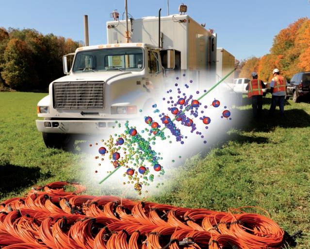
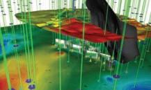
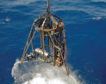
The right team with the right technology backed by unrivalled service and HSE standards – that’s CGGVeritas. We now offer microseismic services to monitor hydraulic fracture stimulation with real-time, in-field processing and a unique combination of advanced survey design and technology for surface and shallow buried array programs. From inception to completion, we offer integrated microseismic services that incorporate purpose-driven:
• Modeling and design
• Acquisition and real-time data processing
• Post-acquisition processing
• Analysis and interpretation


President Kirk Osadetz • Geological Survey of Canada, Calgary kosadetz@nrcan.gc.ca Tel: (403) 292-7022
Vice President
Robin Mann • AJM Petroleum Consultants rcmann@ajmpc.com Tel: (403) 648-3210
Past President
John Varsek • Cenovus Energy john.varsek@cenovus.com Tel: (403) 645-5417
Finance director
Darren Aldridge • Baker Hughes Incorporated darren.aldridge@bakerhughes.com Tel: (403) 537-3400
assistant Finance director
Andrea Hood • geoLOGIC systems ltd. ahood@geologic.com Tel: (403) 262-1992
Program director
Brett Norris • TransGlobe Energy Corp. brettn@trans-globe.com Tel: (403) 264-9896
assistant Program director
Jon Noad • Murphy Oil Corporation jon_noad@murphyoilcorp.com Tel: (403) 294-8829
serVices director
Chris Seibel • Nexen Inc. chris_seibel@nexeninc.com Tel: (403) 699-4558
assistant serVices director
Michelle Hawke • Apache Canada Ltd. Michelle.Hawke@apachecorp.com Tel: (403) 261-1200
communications director
Jim Barclay • ConocoPhillips Canada
Jim.E.Barclay@conocophillips.com Tel: (403) 532-3889
assistant communications director
Stephen Hubbard • University of Calgary steve.hubbard@ucalgary.ca Tel: (403) 220-6236
outreach director
Steve Dryer • Whiskey Jack Resources Inc. whiskeyjackresources@telus.net Tel: (403) 969-2292
assistant outreach director
Simon Haynes • Statoil Canada Ltd. sihay@statoil.com Tel: (403) 724-0364
executiVe director
Lis Bjeld • CSPG lis.bjeld@cspg.org Tel: (403) 513-1228
A message from the CSPG Service Director, Chris Seibel

For the first five months of this year, the Service Directors’ portfolio has been filled with inaugural events; initiatives to review, renew, and refresh; and the continuity of annual events. The inaugural events included the Volunteer Training Day and an out-oftown Technical Luncheon. Initiatives will include reviewing and amending the awards criteria, and refreshment of the membership survey. All the while, CSPG volunteers have continued to plan and execute the established annual social events in their usual outstanding fashion.
This past February 16, the Volunteer Management System was unveiled at the inaugural Volunteer Recognition Luncheon. The luncheon invitation was extended to all current volunteers and approximately 68 volunteers attended. Martin Teitz, the Volunteer Management System Chair has been working with past and current directors to develop the support system. It is designed to be an aid to all volunteers from aspiring to established, providing support at all stages of a volunteering career. The purpose of the Volunteer Management System is to broadcast opportunities and role descriptions, provide a point of inquiry for aspiring volunteers, provide training, and keep records of all volunteer contributions. There is also an initiative to revitalize the membership committee. This committee will assess the varied interests and demographics of the society to ensure recommendations are made to meet the requirements of the membership at large.
This year the Service Directors are undertaking an initiative to review and, where needed, to amend the awards criteria and qualifications. This will be a collaborative effort between the Service Directors, Past President, and the Award’s Committees. The desired outcome is to have awards reflective of the current industry and to ensure that both technical and volunteer contributions by members of the society are recognized. During this process, the
membership will be canvassed for volunteers to fill the role of chairs of the HM Hunter Award and the Tracks Award. If there are any interested parties, please contact myself, Assistant Services Director Michelle Hawke, or Volunteer Management System Chair Martin Teitz.
This year’s awards ceremony is the evening of Monday May 9, coinciding with the Geoconvention: recovery 2011 Joint Annual Convention. All members are strongly encouraged to attend, as this is a great time for the Society to express it’s appreciation for both technical and volunteer contributions.
Another initiative that has been undertaken is the refreshment of the Membership Survey. The last membership survey, conducted in 2009 provided valuable feedback to the Executive that has helped to guide the Society’s direction. Currently, the format and length of the survey is under review, incorporating recommendations from all directors. This survey creates a very useful data set for the Executive and greatly influences future recommendations and policies. I strongly encourage members to take the time to fill out the survey when it is issued.
(Continued on page 7...)
Join us in celebrating the 2010 CSPG Award Recipients Monday, May 9, 2011
Hyatt Regency Calgary, Imperial Ballroom 6:00 p.m. - 7:30 p.m.
This event is open to the public.


Collaborate. Geophysical, land and geological teams work in the same data environment with integrated interface options, targeted towards their workflows. Share. Share spatial and relational data connecting exploration teams and helping to mend data silos. Make Better Decisions. Collaborate on decision points and share information within the same data environment.

AAPG
AGAT LAborATories
APAche cAnAdA LTd.
APeGGA Arc FinAnciAL corPorATion
AyrTon exPLorATion consuLTinG LTd.
bAker ATLAs
bLuebAck reservoir
boyd PeTroseArch
cAnAdA brokerLink
cAnAdiAn nATurAL resources LTd.
cAsey & AssociATes
cenovus enerGy inc.
cGG veriTAs
coLorAdo schooL oF mines
conocoPhiLLiPs cAnAdA LimiTed devon cAnAdA corPorATion divesTco inc.
encAnA
enerPLus resources Fund
FuGro Airborne surveys corP.
FuGro – JAson
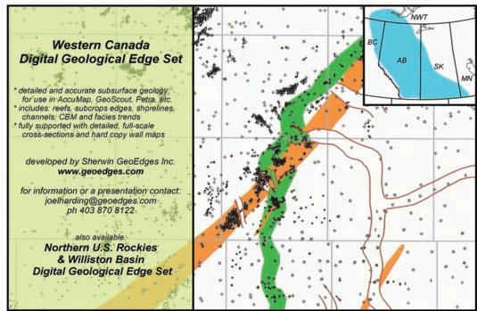
GeoedGes inc.
geoLoGic systems ltd.
GeomodeLinG TechnoLoGy corP.
GeosTrATA resources inc.
hALLiburTon enerGy services
hunT oiL comPAny oF cAnAdA husky enerGy inc.
ihs
imPeriAL oiL resources
LArio oiL & GAs comPAny
LiTTLe rock documenT services
LorinG TArcore LAbs LTd.
mJ sysTems
murPhy oiL comPAny
neurALoG
nexen inc.
Penn WesT enerGy TrusT
PeTrocrAFT ProducTs LTd.
PLusPeTroL
ProvidenT enerGy LTd.
rPs enerGy
schLumberGer cAnAdA LTd.
sensor GeoPhysicAL LTd
sheLL cAnAdA LimiTed
sProuLe AssociATes LimiTed
suncor enerGy inc.
TALismAn enerGy
ToTAL e&P cAnAdA LimiTed
TourmALine oiL corP.
Tucker WireLine LTd.
WeATherFord LAborATories
(...Continued from page 5)
The inaugural out-of-town Technical Luncheon was held on m arch 30 in regina at the ramada hotel. The speaker was Gerry reinson, and the event was coordinated jointly with the saskatchewan Geological society. This initiative partially falls under three portfolios of the society: technical, outreach, and services. The intention of holding a Technical Luncheon in a location other than calgary is to reach out to the decentralized membership while disseminating superb technical material, promoting the society, and recruiting potential new members. hopefully this will be the first of many Technical Luncheons in centres outside of calgary.
This year’s calendar of social events will include all the events that are so popular with the membership: the squash Tournament (which took place February 4-5), LongTime members reception ( may 10), classic Golf (June 15-17), mixed Golf Tournament (August 26), 10 k road race and Fun run (september 13), and the under-35 social (late - 2011). These important events allow the membership to network and build relationships while having fun outside the work environment. The volunteer chairs and committees of each event are outstanding at planning and executing these events year after
year and deserve credit for their fantastic contribution to the csPG.
Last year, the inaugural under-35 social event was held. The intent of this event, the initiative of the past service director Ayaz Gulamhussein, is to reach out to the under-35 membership of the society and to encourage their participation in the cs PG as they build their careers. Ayaz has graciously volunteered to organize this event again, so watch the reservoir and website for an announcement of the date and location.
Planning and executing inaugural events, new initiatives, and annual events will require volunteers. The cs PG depends almost entirely upon volunteers to ensure that we remain a vibrant and relevant professional geologic society that meets the needs and interests of its membership. volunteering provides an excellent opportunity for personal and professional growth while networking with your fellow geoscientists. if you would like to get involved and volunteer, do not hesitate to contact either myself, Assistant services director michelle hawke, or volunteer m anagement system chair martin Teitz for assistance.

Advances in Applied Geomodeling for Hydrocarbon Reservoirs

SPEAKER
Paul MacKay Shale Petroleum Ltd.
11:30 am, thursday, may 26, 2011 calgary, teLus convention centre calgary, alberta
Please note: t he cut-off date for ticket sales is 1:00 pm, t hursday, m ay 19, 2011. csPg m ember t icket Price: $42.00 + gst n on- m ember t icket Price: $45.00 + gst
Webcasts sponsored by
Each CSPG Technical Luncheon is 1 APEGGA PDH credit. Tickets may be purchased online at https:// www.cspg.org/eSeries/source/Events/index.cfm.
Fracture analysis in petroleum systems is a rapidly expanding field of study in the Earth Sciences. Interest in the analysis of fracture systems is driven by the recognition of the essential role that fractures play as fluid conduits within the earth’s crust. For the past few decades, recognition of the importance of fractures as fluid pathways has grown. Much of this recognition has been driven by the petroleum industry as it seeks new unconventional reservoirs to replace declining production from older more conventional
reservoirs. The challenge in fracture analysis is no longer the identification of fracture systems, but rather to quantify the effect of the fractures on fluid migration and the effectiveness of transmitting fluids through rock.
Fractures form, or stated more simply, rock breaks when the stress conditions within the rock exceed the strength characteristics of the rock. Failure in rock is a function of the stresses acting on the rock and the mechanical strength of the rock. For failure to occur, the effective stresses acting on the rock must exceed the physical strength of the rock. The effective stress acting within the crust is strongly influenced by fluid pressure.
In the sedimentary section, the fluids available to the failure mechanism are either water or hydrocarbons. Any other fluids that may be available are in such small quantities as to be insignificant. Water is an incompressible fluid and is an excellent source to create elevated fluid pressures, especially in systems that form in poorly lithified rock, as well as systems that are undergoing compaction. In these systems, the compaction process results in elevated fluid pressures conducive to failure. In active deformations systems that are propagating through older strata or lithified rock, the use of water as the principal fluid source becomes problematic as the amount of water is limited and the system has compacted in a manner that does not favour the easy transfer of water from one horizon to another. In these cases, the source of the fluid is more likely to be hydrocarbons that form as the strata are buried and heated.
There are many components to fracture analysis. To fully describe the fracture network, it is necessary to describe the orientations of the fractures, the connectivity of the fractures, the extent and aperture of the fractures, and their ability to conduct fluid (both quantity and type). The intensity (or density) of the fracture system is also important, both in terms of fluid conductivity and in terms of fluid storage. Ultimately, what is of greatest use to the reservoir analyst is how the fractures hydraulically connect the reservoir to the well bore.
It is possible to estimate the connectivity of the fracture system within the reservoir using a stereonet. Plotting the poles of the fractures on a stereonet will give insight into the connectivity of the fracture system.
If connectivity describes how well fractures intersect, there also needs to be a method of determining how many fractures exist within a given volume of rock. The term fracture intensity refers to the sum of the area of all fracture planes in a given volume of rock. Typically, scan-line analysis is used to approximate the fracture intensity, where the number of fractures intersected by a scan line of set length gives a number of fractures per unit distance.
The advantage of scan-line analysis is that it creates a mathematical function that can be analyzed using a variety of statistical tools. Summing algorithms and frequency analyses are effective tools and give quantitative results that may be compared to productive capabilities. The technique lends itself to comparison within a reservoir, and also comparison from one reservoir to another. An advantage to the technique is that it has statistical predictive capabilities. This technique can be expanded to look at fracture systems in planes. This moves
the analysis from one-dimensional line analysis to two-dimensional planar analysis.
Trend analysis, relative amplitude comparison, statistical spreads may all be determined using this technique. The tool is particularly strong for the analysis of curvature and coherency in 3D seismic data volumes. What is of particular interest to the reservoir analyst is that these values can be compared directly to well data and the effectiveness of the drilling program may be assessed.
Paul MacKay received a B.Sc. (honours, geological
sciences) from Queen’s University in 1980 and a Ph.D. from the University of Calgary (1991). He initially worked for Amoco Canada then moved to Morrison Petroleums, Northstar Energy, and Devon Canada before beginning an international consulting practice. He is currently President of Shale Petroleum Ltd. His expertise is in fracture systems and petroleum exploration and development in structurally complex reservoirs. He teaches field courses in Structural Geology/Geophysics in the Canadian Rockies and field seminars on Fractured Reservoirs based in Wyoming. He is an Adjunct Professor in the Department of Geology and Geophysics at the University of Calgary.

Designed to efficiently print brilliant logs, the NeuraJet17 prints any size log up to 17 inches wide. The top of form feature and the stacker mean little to no supervision is required. See why the NeuraJet17 is the ideal log printing solution.
• Designed for continuous fanfold paper • Automatic top of form loading & stacking
• Print speeds up to 2 inches per second
• Includes log editing & printing software

breakthrough in fracture recognition from seismic –important implications for resource operations and recoveries
SPEAKER
Ralf Oppermann OPPtimal Exploration and Development Pty Ltd.
11:30 am
t hursday, June 9, 2011 c algary, te L us c onvention c entre c algary, a lberta
Please note: the cut-off date for ticket sales is 1:00 pm, monday, June 6, 2011. csPg member ticket Price: $42.00 + gst. non- member ticket Price: $45.00 + gst.
Each CSPG Technical Luncheon is 1 APEGGA PDH credit. Tickets may be purchased online at https://www.cspg.org/eSeries/source/Events/ index.cfm.
Fault and fracture networks can significantly impact reserve recovery and productivity, and can also have significant effects on drilling, mining, and the safety of resource operations. Due to this, various automated fault-extraction techniques have been developed for 3D seismic data in recent years. These techniques aim to support or replace manual fault-mapping efforts, which are typically labour-intensive, timeconsuming, imprecise, and subjective. Ultimately, automated fault-extraction offers the opportunity to replace the interpretation of faults with the direct measurement of faults.


Webcasts sponsored by
This talk will present an innovative and ‘world-first’ method that has been developed to integrate highest-resolution 3D image processing results with the detailed
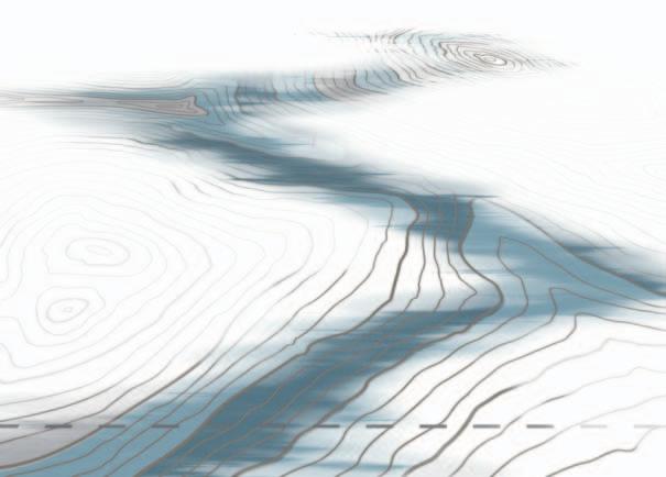
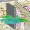
No seismic faults identified or predicted from Reflectivity data: ‘sub-seismic’ faults “hit and miss” fracture development drilling


Fault identification: multiple seismic faults penetrated by well: ‘sub-visual’ faults targeted fracture development possible !
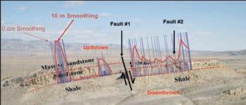
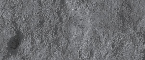
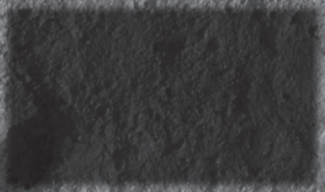
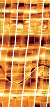
Figure 1. High-resolution fault extraction visualises small-scale spatial changes in amplitude, frequency, or phase content of 3D seismic data, and challenges perceptions of what can and can not be identified with seismic data. Comparison and calibration of seismic fault extractions with faults identified in wells (from core, image logs/dipmeter, log correlation) helps to ground-truth extractions and assess the true seismic fault resolution of a particular data set at objective level.
faults
Cut-off automated fault mapping:
Oil & Gas: ca. 5-8m Coal Mining : ?0.5-1m
Coal Mining Cut-off visual fault mapping (1-3m throw) 1mm 1cm10cm1m10m100m 1km
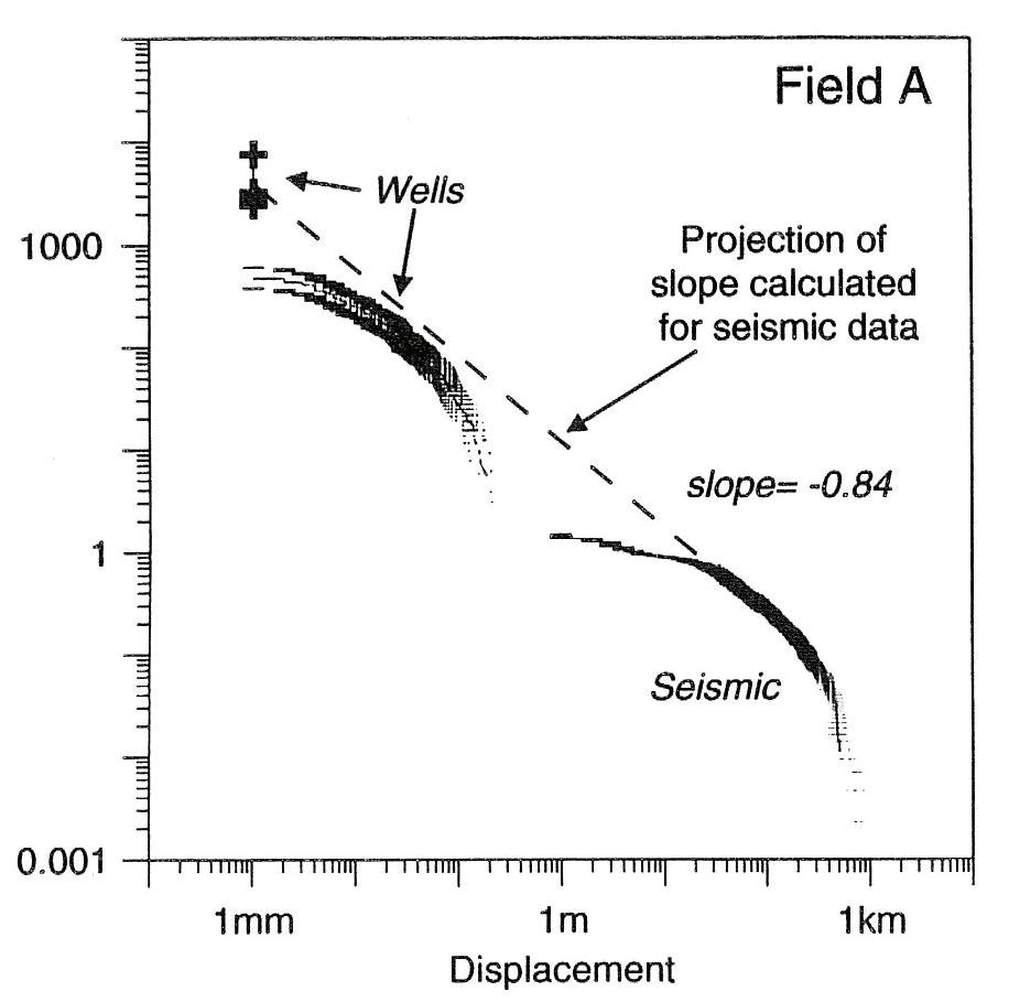
Oil & Gas Cut-off visual fault mapping (20-30m throw)
Figure 2. Comparison of visually mapped seismic fault-throw data with well displacement data (modified from Needham et al., 1996). Displayed also are the cut-off ranges for visual fault mapping from deep, lowresolution oil and gas 3D surveys and shallow, high-resolution Coal Mining 3D surveys. These cut-offs for low and hi-res 3D surveys can both be lowered by automated fault extraction.
calibration and review of various seismic, well, and mining data. It will be shown that the method delivers groundbreaking insights into the physical description of resources (Figure 1).
Properly calibrated fault and fracture network volumes deliver faster and more reliable and objective fault evaluations, and a better understanding of structural geometries and fault populations. The key benefit of hi-res, automated fault extraction, however, is a marked increase in fault
resolution, which results in a significant increase in the number of medium-sized faults that are identified from seismic (i.e., faults with displacements between 30 and ca. 5m for deep/low-resolution 3D surveys; Figure 2).
With decreasing fault throw (i.e., reflector offset) visual interpretation becomes more and more challenging and subjective, and visual fault-mapping confidence decreases accordingly. This is where Automated Fault Extraction can help to objectively and more
confidently visualise faults, particularly faults with small displacement. Automated Fault Extraction reduces the cut-off for seismic fault recognition and can provide information on faults at ‘sub-visual’ level, approaching the true seismic resolution limit for the detection of faults in a particular data set. These sub-visual, or medium-scale faults are currently incorrectly, but consistently and industry-wide, included into the subseismic and ‘un-mappable’ category by many geoscientists, but can in fact be extracted from seismic data with latest technology, experience, and careful calibration with other data. It follows from this, that most 3D surveys in the resource industries are currently under-utilized when it comes to fault identification, as an entire mediumsized, sub-visual (but not sub-seismic) fault population can be extracted from already existing data with relatively little effort.
Examples from fractured and compartmentalised reservoirs around the world, as well as unconventional reservoirs (tight gas, shale gas, basement reservoirs) demonstrate that the new techniques can delineate potential fluid barriers, fluid conduits, or geomechanical instability areas in the subsurface at a much higher resolution than achieved by other current methods.
With the increased resolution, much higher fault/fracture densities are found than were previously recognized. Instead of identifying, for example, only the 10 largest faults in a field through visual mapping efforts, 100 or 1,000 smaller faults can be additionally made visible through hi-res automated fault extraction.
This, in turn, allows the identification of
many fault penetrations in wells that were previously not recognized from seismic data, or even from well data, particularly in intervals where no core, dipmeter, or image logs have been acquired. These newly identified seismic fault penetrations are often directly linked with drilling problems (e.g., fluid losses, geomechanical/borehole stability issues) or production problems (e.g., water or gas channelling along fault planes, compartmentalisation, etc.). Importantly, they can be also directly linked with hydrocarbon shows and productivity, especially in fractured and unconventional reservoirs, where these faults can provide direct access to productive natural fracture networks.
The comparison of the new hi-res seismic fault and fracture networks with drilling and production issues suggests that a new dimension in the visualization and understanding of resources has been opened. The presentation will aim to show that a focused application of the new technology workflows can deliver increased recoveries from resources, and that it can also result in safer, cheaper, and more successful drilling and mining operations. As such, the new techniques are proposed as Best Practise tools for exploration and development planning and execution.
Ralf Oppermann is an independent geoscience consultant with 21 years of international experience in the Oil and Gas industry, working as a seismic interpreter and geologist in integrated, multi-disciplinary exploration, appraisal and development teams. During his career, he has worked as international staff for various Shell Operating Companies in the Netherlands, U.K.,

Germany, Malaysia, and New Zealand, as well as working with Chevron in Australia.

In 2008, Ralf founded OPPtimal Exploration & Development Pty Ltd. as a technology service company, to provide new and leading-edge volume interpretation workflows to companies active in oil and gas, shale gas / oil, coal seam gas / coal bed methane, underground gas storage, geosequestration, geothermal, groundwater, coal mining, and ore mining. His company is located in Perth, Australia, and has so far performed fault visualization studies on assets in North America, Europe, Middle East, Asia, and Australasia, for oil and gas, shale gas, geothermal and coal mining companies. Currently, Ralf is working on one of the largest oil fields in the world, a fractured carbonate reservoir in the Middle East.
Ralf is particularly keen to perform further studies on shale gas and coal seam gas assets in North America, as very few of these assets in Australia are currently covered with 3D seismic. He is also trying to find a company who is interested in performing a comparison of his hi-res fault extractions with microseismic data.
Ralf holds an M.Sc. in Geology/Palaeontology and B.Sc. in Business and Economics from the University of Göttingen in Germany. He is a member of the European Association of Geoscientists and Engineers (EAGE), the Formation Evaluation Society of Australia (FESAus), the German Federation of Geologists (BDG), the Petroleum Exploration Society of Australia (PESA), the Petroleum Exploration Society of Great Britain (PESGB), and the Society of Petroleum Engineers (SPE).

Lithosphericscale detachment faulting at oceanic spreading centres: How much of the Earth’s oceanic ‘crust’ is not actually crust?
SPEAKER
Graham Banks , Ph.D.
Formerly at Cardiff University, U. k. Currently at WesternZagros Resources, Calgary
12 noon to 1pm Tuesday, May 3, 2011
Location: Room A, +30 level, Western Canadian Place (Husky Energy), 707-8th Avenue S.W. Calgary, Alberta
About 71% of the Earth’s crust is oceanictype and the other 29% is continentaltype. A widely accepted axiom states that oceanic crust is continually created at oceanic spreading centres – where tectonic plate divergence is accommodated by upwelling magma that accretes new
lithosphere. The anatomy of oceanic crust differs according to spreading rate and is classified into ‘fast’, ‘intermediate,’ ‘slow,’ and ‘ultra-slow’ spreading rate types.
The Troodos ophiolite in Cyprus is an exposed segment of Tethys Ocean lithosphere formed around the intersection of a spreading ridge and a transform fault. It has long been regarded as the type section for slow-spreading oceanic
crust: the optimum place to study magma generation and crustal accretion processes at slow-spreading oceanic ridges.
Three field seasons of integrated igneous, metamorphic, and structural investigation, combined with metre-scale analysis of core Cy-4 (a 2.3km long, continuous vertical section of Troodos middle and lower oceanic crust), revealed a simple, upward sequence of magma chamber


cumulates overlain by expelled sheeted dykes and extruded lavas atop. Tectonic plate divergence was accommodated by high magma supply to the spreading ridge; relatively minor extensional deformation occurred in magmatic and semi-magmatic states. Deformation along the Arakapas Transform Fault Zone was expectedly intense.
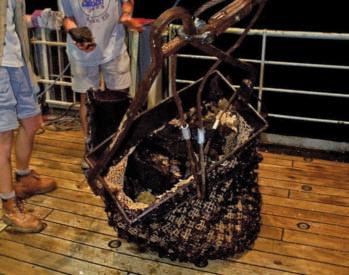
Scientific cruise JR63, aboard the RRS James Clark Ross, permitted direct comparison between the Troodos ophiolite
and recently created slow-spreading oceanic crust. Oceanic lithosphere was investigated at the Mid-Atlantic Ridge 15°45’N (close to the intersection with a major transform fault zone) using oriented cores from wireline drilling (1.5-3.5km water depth), 23 dredge hauls, and deepwater backscatter images. This study area is not ‘typical’ oceanic crust. Corrugated surfaces extending 100s km 2 represent low-angle detachment surfaces, along which mantle is exhumed at the MidAtlantic Ridge. These corrugated massifs
are dominated by highly deformed, brittle, fault rocks and fault striations ranging from 3km wavelength and 200m amplitude to centimetre scale. Sampled rocks are mainly of mantle and lower crust compositions. Strain localisation was highly efficient and long-lived, a result of fault zone weakening during focused hydrous fluid flow into the mantle.
Results of magmatic-tectonic studies across the Troodos ophiolite and at the Mid-Atlantic Ridge challenge axioms of oceanic crust creation and tectonic processes at mid-ocean ridges:
• The Troodos ophiolite resembles fast-spreading oceanic crust and thus cannot be used as the type section for slow-spreading oceanic crust.
• Commonly occurring normal faults exhume mantle into oceanic ‘crust’ at slow-spreading ridge axes, to accommodate tectonic plate separation in the absence of magmatism.
• Intense deformation along these permeable detachment faults, and al ong active transform faults, focuses large volumes of hydrothermal fluid into and out of the mantle at midocean ridges.
• A significant amount of the Earth’s oceanic ‘crust’ may not be crust at all.

SPEAKER
Bob Potter, P.Geol. President, GeoChemTech Inc.
12:00 Noon
Wednesday, May 4th
Nexen Plus 15 Conference Centre
Nexen Annex Building 7th Ave. & 7th Street SW Calgary, Alberta
COUNTR y
Sudan is a country going through a divorce and it is finalized early in July!
With an area of 2,505,810 km2 , Sudan is currently the largest country in Africa and the Arab world, and the tenth largest in
» Reliable & Value-Added: We database and summarize the entire completion operation.
» Analysis Ready: Sortable table and report views, graphing capabilities, fully exportable.
» Expanding Dataset: Growing rapidly, driven by client requests.
Contact us for a live demonstration 403.269.3644 info@canadiandiscovery.com www.fracdatabase.com
the world. It is located in northern Africa, immediately south of Egypt, and has an 853 km coastline along the Red Sea. Sudan is bordered by nine different countries and the world’s longest river, the Nile, divides the country into an east and west sides, with major tributaries including the Blue Nile, the Dinder, and Radah Rivers.
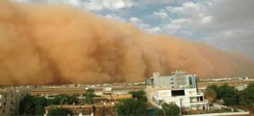
The terrain of Sudan is generally flat plains, broken by several mountain ranges. The amount of rainfall increases from north towards the south with the very dry Nubian Desert in the north and swamps and rainforest in the south. Sudan’s rainy season lasts for about three months (July to September) in the north, and up to six months (June to November) in the south. The dry regions are plagued by sandstorms, known as haboobs.


Sudan has achieved significant economic growth (GDP 6.6% – 2008, 4.2% –2009, and 5.2% – 2010) by implementing macroeconomic reforms and finally ending the civil war with rebel groups in the south by adopting a new constitution in 2005 and granting them limited autonomy. The most significant event this year was the independence referendum held in early January that resulted in a 99% vote in favor of separation.
GEOLOG y
North Africa is composed of three major cratons – West African, Arabian-Nubian, and Congo cratons. All of the MesozoicCenozoic rifting of North Africa occurred between the cratons.
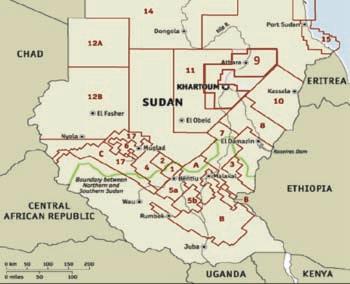
A number of rift basins related to the West and Central African Rift System (WCARS) developed during the Late Jurassic to Early Cretaceous (160 – 100 Ma) synchronous with the separation of South America and Africa. As a result, individual rift basins, Nigeria through Niger and Chad to the Sudan, were created by the extensional forces of the Central African Shear Zone (CASZ). Multi-phase rifting and some basin inversion were in response to changes of regional tectonic. In general, basins of the WCARS share much in common in occurrence and evaluation because they were developed in a similar tectonic setting, though individual basins show unique histories due to local influences.
Sudan has developed oil production from two of the multiple rift basins related
to the CARSZ. At least, six other rift basins in east-central Sudan related to the CARSZ remain basically unexplored. In addition, access to the southern margin of the Muglad Rift has been restricted for over 20 years due to the civil war. The basins of northwest Sudan are poorly defined but current available information indicates two, maybe three, rift basins and an extension of the kufra (Mourdi) basin from Libya. Significant undiscovered hydrocarbon potential exists in the other rift basins in Sudan.
The Sudan current oil production and reserves are:
• Oil Production
486,700 bbls./day (2009 EST.)
• Oil Consumption
84,000 bbls./day (2009 EST.)
• Oil Exports
303,800 bbls. /day (2007 est.)
• Oil Proved Reserve s
6.8 billion bbls. (January 2010 EST.)
• Natural Gas Proved Reserves
84.95 billion cu m (January 2010 EST.)
( S ource: CIA-World Fact Book)
The objective of the talk is to explore the magnitude of the resources within the context of the changing political environment.
y
Bob Potter (Professional Geologist), President and founding principal of GeoChemTech Inc., is a professional explorationist and manager with extensive experience in leading edge technology and multidisciplinary technical teams. His experience includes work in exploration and development in sedimentary basins of Canada, Sudan, Argentina, Thailand, and Kazakhstan.
During the past 40 years, Bob has developed and implemented exploration and business processes that have resulted in the discovery of resources over 280 million barrels of oil equivalent. He understands the application and integration of multiple data sets to reduce risk and to maximize success.
There is no charge. Please bring your lunch. The facilities for the talk are provided complimentary of Nexen, coffee by IHS and refreshments Geochemtech Inc. For further information or if you would like to give a talk, please contact Bob Potter at (403) 8639738 or mail to: ropotter@telusplanet.net or Trent Rehill at (403) 606-6717 or email to: trehill@kulczykoil.ca. Or visit our new Face Book page (“CSPG International Division”).


SPEAKER
Dan Quinsey
Alberta Palaeontological Society
7:30 PM
Friday, May 13th, 2011
Mount Royal University, Room B108
The lure of the mountains and foothills is in us all. Most of us are familiar with the Upper and Lower Foothill regions of Alberta adjacent to the Rocky Mountains which, together with the Rockies, are commonly referred to as the Eastern Slopes. The Foothills are not only home to
some of the most interesting species in the province, including the most inland race of grizzly bears in North America, they also hold evidence of ancient times.
Uncovered within the Lower Foothill regions of Alberta are the Carboniferous and Jurassic formations along Canyon Creek, Moose Mountain where many geological and palaeontological wonders await to be experienced and discovered.
The objective of this talk is to offer fellow enthusiasts an opportunity to experience the magnificence of Canyon Creek, Moose Mountain. The focus will be on the geological and palaeontological features of the area, a brief survey of the exploration history, and a look at the common flora and fauna along the way.
BIOGRAPH y
Dan Quinsey has been a member of the Alberta Palaeontological Society for over 10 years and currently holds the positions of Past President and Chairperson of the Public Outreach / Education Committee. Dan has a Baccalaureate in Palaeontology from
Mount Royal University, Degrees in Business Management from Chinook Learning Services and Electronic Data Processing from Loyalist College, and Undergraduate Degrees in Systems Analysis and Design and Architectural Drafting also from Loyalist College.
Current and previous affiliations include the Tyrrell Museum of Palaeontology, Calgary Junior Chamber of Commerce – J AYCEES, C algary Philatelic Society, and Big Brothers and Big Sisters of Calgary and Area.
Dan has published work in Deposits Magazine (UK), Kick-started the APS Guide to Common Vertebrate Fossils from the Cretaceous of Alberta book project, and is currently working on another book titled Moose Mountain, Alberta – Exploring the Natural History of Canyon Creek and Area.


• Fracture detection
“We set the wrong course and headed due north1” – Pitfalls
SPEAKER
Ali Dalir, P.Geol. Schlumberger Canada Limited, Consulting Services
12:00 Noon
Wednesday May 25, 2011
Place TBD
ABSTRACT
Geological modeling has been a hot topic for the last decade. Nowadays, modeling is part of development planning for most of the conventional and unconventional reservoirs. As a result, the demand for modeling has been growing continually, and the modeling work has spread among many geologists and geophysicists, rather than a few highly specialized experts. While this is beneficial for the industry and the field, it comes with a price. Many of the geological models are constructed by fresh-to-the-field professionals, which can be victim of one or more of the known pitfalls of the modeling. There has been a fairly regular pattern of these pitfalls, and this talk aims to share the experience from dealing with these pitfalls, and possibly open the discussion for the experts of the field to weigh in.
The talk addresses some of the well known flaws in geological modeling like unclear objectives, lack of a conceptual model, improper theory, substandard data, inefficient use of seismic data, lack of a facies model, and improper application of geostatistics. A list of possible pitfalls in geological modeling will be discussed, based on the experience from working with E&P companies in Canada and internationally, and the discussion will be opened for audience for feedback and input.
Ali Dalir received his Bachelor’s degree in geology in 1997 and his Master’s degree in Sedimentology and Sedimentary Petrology in 2003 from University of Tehran. He worked as a field geologist for about four years before he joined Schlumberger in 2003. He was introduced to geological modeling in 2004 and has been developing geological models for oil and gas reservoirs since then. In 2007, he started his Master’s of Reservoir Characterization at the University of Calgary and successfully completed the program in 2008. Since 2007 he was also part of the Consulting team in Schlumberger Canada Limited, with his main focus on reservoir characterization and modeling. Ali has extensive experience in reservoir characterization and geological modeling. He has developed several geological models of conventional and unconventional reservoirs for oil and gas companies in Calgary and internationally.
INFORMATION
There is no charge for the division talk and we welcome non-members of the CSPG. Please bring
your lunch. For details or to present a talk in the future, please contact Weishan Ren at (403) 2333428, e-mail: weishan.ren@conocophillips.com.
List of the topics to be presented in the talk: Pitfalls of modeling:
• Introduction
• Why this title
• Past experience
• Importance
• Impacts
• Wrong/unclear objectives
• What drives production
• Catch with the beautiful pictures: It looks nice, so it must be true!
• Conceptual model
• Facies/Core Analysis
• Improper theory/ insufficient knowledge
• Input Data quality
• Coordinate system
• Well head
• Tops
• MD/TVD
• Logs/ Normalization/ service company/ Measurements
• Framework: Seismic
versus well tops
• Correlation
• Horizons
• Faults/ Compartments
• Properties
• Spatial connectivity
• Facies versus zones/ units
• Electrofacies
• Geostatistical discrepancies
• Clustering
• Outliers
• Horizontal wells
• Porosity
• Water Saturation
• Permeability
• Conventional versus unconventional plays
• TOC
• Low porosities
• Integration. Bring all the data together
• That’s different than what I was expecting!
• Peer review
• A set of fresh eyes
1“Hush Sound, Where we went wrong” http://www.youtube.com/watch?v=sznbNbaJZd4

| By E. R. (Ross) Crain, P.Eng.
Unicorns are beautiful, mythical beasts, much sought after by us mere mortals. The same is true for petrophysical models for unconventional reservoirs. This is the seventh in a series of review articles outlining the simple beauty of some
practical methods for log analysis of the unusual.
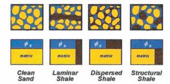
Porosity and water saturation in laminated shaly sands, and in other cases of anisotropic reservoirs, are a special case, not amenable to conventional petrophysical solutions. Isotropic reservoirs are those in which the physical properties are the same regardless of the direction of measurement. Anisotropic reservoirs have one or more properties that vary with direction.
The best known anisotropic property is resistivity, which can vary by a factor of 100 or more, depending on whether the measurement is made parallel to the bedding or perpendicular to it. This is the situation that exists in most so-called “low-resistivity pay zones”. These are usually laminated shaly sands but can also be sandstones or carbonates with thinly bedded variations in porosity. In resistivity log analysis, anisotropy is present when the bedding is thinner than the tool resolution and is sometimes described as a “thin-bed” problem.
Rocks of this type are called transverse isotropic; there is little horizontal anisotropy, so resistivity differs between only two axes – vertical and horizontal. Channel sands with significant cross-bedding and other linear depositional features could be anisotropic on all three axes.
There are no logs that measure resistivity in three orthogonal axes at the same time. The newest induction logs measure horizontal and vertical resistivity (directions relative to tool axis). Azimuthal laterologs read in eight directions (perpendicular to the tool axis) and could be used to look for horizontal anisotropy in semi-vertical wells.
The newest thin-bed tool is described as a thin-bed Rt tool. It is a microlaterolog type of device with a bed resolution of 5 cm and a depth of investigation between 30 and 50 cm (12 to 20 inches), about 2 to 3 times deeper than earlier microlaterologs. If invasion is shallow, the resistivity approaches a deep resistivity measurement. This is very useful in laminated shaly sands where the laminae are relatively thick.
Other thin-bed logging tools are the microlog, microlaterolog, proximity log, and micro-spherically focused log. These tools measure 3 to 12 centimeters of rock but have a depth of investigation of similar dimensions.
In some laminated sands, these tools can be used to determine net-to-gross sand ratio. The electromagnetic propagation log measures in the order of six centimeters, but it is a porosity and shale indicator tool, not a deep resistivity tool. Some sonic logs can be run with a 15 cm (6 inch) bed resolution.
The resistivity microscanner can see beds as thin as 0.5 cm and fractures as thin as 1 micron. The acoustic televiewer can resolve beds to 1 or 2 cm. Accurate net-to-gross ratios can be determined, but again, the resistivity of the sand fraction beyond the invaded zone cannot be determined from these tools.
None of the tools listed above provide a useful deep resistivity value when laminations are thinner than the tool resolution, so unconventional log analysis models are needed.
The problem lies in how resistivity logs average laminations that are thinner than the tool resolution. Most logs average the data in a linear, thickness-weighted fashion, but induction and laterologs average conductivity and then convert it to resistivity. In shaly sands, the conductivity of the shale laminations is usually much higher than the gas- or oil-sand laminations, the resulting conductivity is high (resistivity is low). This makes the zone look like a poor-quality reservoir, maybe so poor that it will not be tested, thus bypassing considerable oil or gas.
A similar problem exists in laminated porosity. The low-porosity laminations have higher water saturation than oil- or gas-bearing higher porosity laminations. The measured resistivity of the laminated hydrocarbonbearing reservoir is often close to the truth, but the calculated water saturation of water zones may be misleading.
To illustrate the simplest case, assume a laminated shaly sand sequence with shale laminations equal in thickness to the sand laminations. This gives a shale volume (Vsh) averaged over the interval of 50%. Assume the porosity and resistivity values are as shown below:
The upper part of Table 1 shows that the


(...Continued from page 18)
average resistivity of a 50:50 mix of 4 ohm-m shale laminations with 200 ohm-m sand laminations is 7.9 ohm-m, based on the measured conductivity. If the sand laminations are wet, as in the lower part of the table, the average resistivity is close to that measured by the conductivity log. Note, too, that the recorded resistivity contrast between a water zone and a gas zone is small, so it may not be possible to recognize gas when it is present, especially if water resistivity varies between one hydrodynamic regime and another.
Water saturation based on the measured resistivity will be very misleading, often showing the zone to be wet when it is not. We will see later how we might overcome this and maybe even find out the true sand lamination resistivity of 200 ohm-m. The correct Sw comes from the 200 ohm-m resistivity, not the 7.9 ohm-m measured by the standard logging tool.
In the early days of log analysis, this phenomenon was attributed to many different, almost mystical, reasons because the parallel nature of the conductive paths was not understood by many analysts.
The case of laminated porosity is slightly different. The resistivity contrasts are smaller than the laminated shaly sand case. The resistivity of the higher porosity streaks with low water saturation may be close to that of the low porosity streak with higher water saturation. But water zones may look pretty resistive, again giving misleading water saturation.
Assume equal thicknesses of high and low porosity with the porosity and resistivity values as shown below:
Modeling laminated shaly sands or laminated porosity with a spreadsheet is the only way to understand the resistivity response and resulting water saturation – usually counterintuitive, always surprising. A spreadsheet for these models is available as a free download on my website at www.spec2000.net .
Some newer induction logging tools provide a vertical conductivity measurement as well as the usual horizontal measurement. If the beds are still parallel to the horizontal induction log signal, the vertical induction signal will give an average of the resistivity of the beds
instead of averaging the conductivity. This is because the normal induction averages the beds in a parallel electrical circuit and the vertical induction sees a series circuit.
Assume a laminated shaly sand with horizontal bedding, a vertical borehole, and a logging tool that can measure both vertical and horizontal conductivity:
1. CONDhorz = VSHavg * CONDshale + (1 - VSHavg) * CONDsand
2. RESvert = VSHavg * RESshale + (1 - VSHavg) * RESsand
3. REShorz = 1000 / CONDhorz
4. CONDvert = 1000 / RESvert
5. AnisRatio = RESvert / REShorz
OR 5. AnisRatio = CONDhorz / CONDvert
6. AnisCoef = AnisRatio ^ 0.5
Where:
AnisRatio = anisotropic ratio
AnisCoef = anisotropic coefficient
CONDhorz = horizontal conductivity (mS/m)
CONDvert = vertical conductivity (mS/m)
CONDsand = sand lamination conductivity (mS/m)
Table 1. In a laminated shaly sand with 50% shale volume, the
less than 8 ohm-m – pretty scary, but that is what real induction and laterologs do!
and
is
oiL or gas case – Laminated PorositY
Table 2. The “RESD from COND” column shows the value a real logging tool would read in the laminated porosity. It can be higher or lower than the thickness-weighted average of the two individual resistivities, depending on the porosity and water saturation of the two layers. The correct Sw is derived by calculating PHIe times Sw for each layer, adding them up, and dividing by the average PHIe.
CONDshale = shale lamination conductivity (mS/m)
REShorz = horizontal resistivity (ohm-m)
RESvert = vertical resistivity (ohm-m)
RESsand = sand lamination resistivity (ohm-m)
RESshale = shale lamination resistivity (ohm-m)
VSHavg = shale lamination volume within the interval measured by the logging tool (fractional)
Equations 5 and 6 are as defined by Schlumberger in 1934. Some authors invert the equations so the coefficient is less than or equal to 1.0.
Equations 1 and 2 can be solved simultaneously for any two unknowns if the other parameters are known or computable. For example, we can solve for RESsand and RESshale if RESvert and REShorz are measured log values and VSHavg is computed from (say) the gamma ray log over an interval. Alternatively, we can solve for RESsand and VSHavg if we assume RESshale = RSH from a nearby thick shale:
8. CONDsand = CONDvert * (CONDshale - CONDhorz) / (CONDshl - CONDvert)
9. VSHavg = (CONDhorz - CONDsand) / (CONDshale - CONDsand)
If you prefer to think in Resistivity terms:
10. RESsand = REShorz * (RESvertRESshale) / (REShorz - RESshl)
11. VSHavg = (RESsand - RESvert) / (RESsand - RESshale)
RESsand is then used in Archie’s water saturation equation, along with porosity from core or from a laminated sand porosity method, for example:
12: PHINsand = (PHIN - VSHavg * PHINSH) / (1 - VSHavg)
13: PHIDsand = (PHID - VSHavg * PHIDSH) / (1 - VSHavg)
14: PHIsand = (PHINsand + PHIDsand) / 2
15: SWsand = (A * RW@FT / ((PHIsand^M) * RESsand))^(1/N)
Where:
PHINsand = neutron porosity of a sand lamination
PHIN = neutron log reading in the laminated sand
PHINSH = neutron shale value in a nearby thick shale
PHIDsand = density porosity of a sand lamination
PHID = density log reading in the laminated sand
(Continued on page 22...)
(...Continued from page 21)
PHIDSH = density shale value in a nearby thick shale
PHIsand = effective porosity of a sand lamination
SWsand = effective water saturation of a sand lamination
RW@FT = water resistivity at formation temperature (ohm-m)
A, M, and N = electrical properties of a sand lamination
Equations 10 through 15 can be plotted versus
depth, but this may be misleading since only some of the interval has the porosity and water saturation that is displayed – some of the reservoir interval is nearly pure shale. Oil or gas in place must be adjusted by the net to gross ratio based on the average shale volume:
16: Net2Gross = (1 – VSHavg)
17: NetSand = (1 – VSHavg) * GrossSand
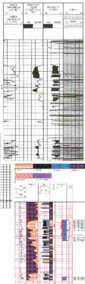
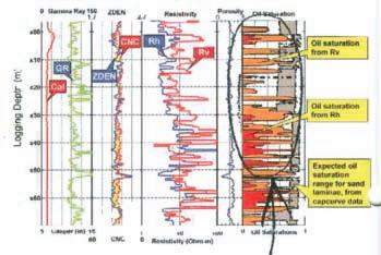
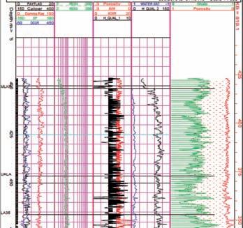
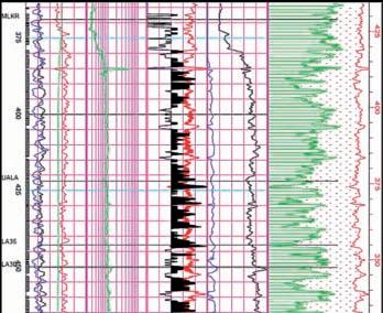
Vertical resistivity logs are still very rare, but are the tool of choice for laminated shaly sands. An example is shown in Figure 5.
Notice the large difference between Rv and Rh on the raw log and the difference in Sw on the computed log.
3-D INDUCTION LOGS IN DIPPING BEDS
The example given above involved a laminated shaly sand with bedding perpendicular to the borehole axis (horizontal bedding, vertical borehole). When beds dip relative to the borehole, the situation becomes more complicated. The relative dip is the important factor and takes a bit of thought when the borehole is not vertical.
Dipmeter results are presented as true dip angle and direction relative to a horizontal plane and true north. To obtain dip and direction of beds relative to a logging tool in a deviated borehole, you need the borehole deviation and direction from a deviation survey. This is often obtained at the same time as the dipmeter, but may come from some other deviation survey, either continuous or station by station. you need to rotate the true dips into the plane perpendicular to the borehole to get the final relative dip.
For a conventional induction log, the apparent conductivity is:
18. CONDlog = ((CONDhorz * cos(RelDip))^2 + CONDvert * CONDhorz * (sin(RelDip))^2)^0.5
Where:
CONDlog = conductivity measured by a log in an anisotropic rock (ms/m)
ReLDip = formation dip angle relative to tool axis
When relative dip is 0 degrees (horizontal bed, vertical wellbore), the conventional log reads CONDhorz, as we know it should. However, if relative dip is 90 degrees, as in a horizontal hole in horizontal laminated sands, the log reading is (CONDhorz * CONDvert) ^0.5. This is a surprise, as we might have expected the tool to measure CONDvert.
If two deviated wells are logged through the same formation (at considerably different deviation angles), two equations of the form of equation 18 can be formulated and solved for CONDhorz and CONDvert. RESsand and VSHavg can then be calculated as in equations 10 and 11.
In the absence of a vertical resistivity measurement, we can make some assumptions and use a non-conventional analysis model. These models do not generate log curves that can be plotted versus depth. Instead, they look at stratigraphically significant layers and generate the average
properties for each layer.
MODEL 1: An obvious solution is to use the math for the vertical resistivity model (equations 10 through 17 given earlier) with assumed values of RESsand (based on a model of a clean sand) and Vsh (based on the GR log). The results would give
(Continued on page 24...)
(...Continued from page 23)
an indication of the reservoir quality of the individual layer analyzed. Permeability, pore volume (PV), hydrocarbon pore volume (HPV), and flow capacity ( kH) are calculated from the above results, just as for conventional sands, bearing in mind that the results apply only to the NetSand portion of the gross interval. No depth plot would be available as the results apply to the whole layer.
MODEL 2: Another model uses rules for finding the rock properties based on shale volume, along with constants derived from core analysis. These empirical rules can be calibrated to core and then used where there is no core data. The PHIMA x porosity equation and Buckles water saturation equation given below are widely used in normal shaly sands where the log suite is at a minimum, and are equally useful in the laminated case:
18: VSHavg = average Vsh from GR or
density neutron separation over the layer’s gross interval
19: Net2Gross = (1 - VSHavg) or from core, televiewer, or microscanner
20: NetSand = (1 - VSHavg) * Gross
21: PHIsand = PHIMA x 22: SWsand = kBUCkL / PHIsand OR 22: SWsand = (A * RW@FT / ((PHIsand^M) * RESsand))^(1/N)
Where:
PHIMA x = maximum porosity expected in the clean sand laminations kBUCkL = Buckle’s number, product of porosity times water saturation expected in a clean sand lamination
This model presupposes that the laminated sand is hydrocarbon bearing. Again, permeability, pore volume (PV), hydrocarbon pore volume (HPV), and flow capacity ( kH) are calculated from the above results, just as for conventional sands, bearing in mind that the results apply only to the NetSand portion of the gross interval.
The PHIMA x value is the critical factor. If a moderate amount of core data is available for the sand fraction of the laminated sand,
this data can be mapped and used to control PHIMA x spatially. RESsand can be assumed from a nearby clean hydrocarbon-bearing sand or by inverting the Archie equation with reasonable values of PHIMA x , RW@ FT, and SW. kBUCkL is usually in the range 0.035 to 0.060, varying inversely with grain size of the clean sand fraction.
A very minimum log suite can be used, since the only curve required is a gamma ray shale indicator, but only if there are no radioactive elements other than clay. This is not the case in the Milk River, so a minimum log suite will not work here. We have used the minimum suite successfully in laminated shaly sands in Lake Maracaibo.
MODEL 3: This model uses the linear log response equation to back-out the clean sand fraction properties from the actual log readings and the shale properties. The response equations are used on the average of the log curves over the gross sand interval. We still assume:
23: VSHavg = average Vsh from GR or density neutron separation over gross interval
24: Net2Gross = (1 - VSHavg) or from core, televiewer, or microscanner
25: NetSand = Gross * Net2Gross
than 5 that are not worth perforating.
26: PHINsand = (PHINavg – VSHavg * PHINSH) / (1 - VSHavg)
27: PHIDsand = (PHIDavg – VSHavg * PHIDSH) / (1 - VSHavg)
28: PHIsand = (PHINsand + PHIDsand) / 2
29: CONDsand = (CONDavg – VSHavg * 1000 / RESshale) / (1 - VSHavg)
30: RESDsand = 1000 / CONDsand
31: SWsand = kBUCkL / PHIsand OR 31: SWsand = (A * RW@ FT / ((PHIsand^M) * RESDsand))^(1/N)
Where:
xxxxavg = log value averaged over a discreet laminated sand interval, thicker than the tool resolution
This model has the advantage of using fewer arbitrary rules and more log data, including resistivity log data. The critical values are RESshale, PHINSH, and PHIDSH, which are picked by observation of the log above the zone. It can still be calibrated to core by adjusting these parameters. If the Archie water saturation equation is used, it might distinguish hydrocarbon from water. The Buckle’s saturation presupposes hydrocarbons are present.
The layer average PHIDsand and PHINsand can be compared to each other to see if they are similar values – they should be if the parameters are reasonably correct. They could cross over if gas effect is strong enough. Our results showed a 0.02 porosity unit variation on the best behaved wells, indicating that the inversion of the response
equations was working well. However, on some intervals in some wells, the results were not nearly so good.
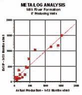
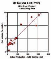
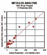
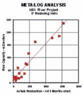
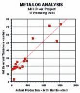
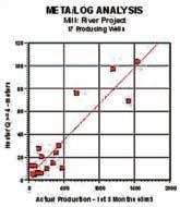
There are a number of ways to assess reservoir quality. In laminated sands. One approach is to correlate first three months or first year production with net reservoir properties from one of the laminated models described above. The following example used Model 3 and is from “Productivity Estimation in the Milk River Laminated Shaly Sand, Southeast Alberta and Southwest Saskatchewan” by E. R. (Ross) Crain and, D.W. (Dave) Hume, CWLS Insite, Dec 2004.
We chose to use the first 8,760 hours of production (365 days at 24 hours each) divided by 4 (3 months of continuous production) as our “actual” production figure. This normalizes the effects of testing and remedial activities that might interrupt normal production.
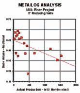
The normalized initial production was correlated with net reservoir thickness, pore volume (PV), hydrocarbon pore volume (HPV), and flow capacity ( kH). Correlation coefficients (R-squared) are 0.852, 0.876, 0.903, and 0.906 respectively. The correlation is made using data calculated over the total perforated interval. Average shale volume was correlated with actual production but the correlation coefficient was only 0.296,
although the trend of the data is quite clear. Correlation of actual production versus the various reservoir properties are shown in Figures 7 through 11.
Productivity estimate based on Model 3 results and a log analysis version of the productivity equation can be used as well. The equation is:
32. ProdEst = 6.1*10E-6 * kH * ((PFPS)^2) / (TF + 273) * FR * 90
Where:
kH = flow capacity (mD-meters) (PF - PS) = difference between formation pressure and surface backpressure ( kPa)
TF = formation temperature (degrees Celsius)
FR = hydraulic fracture multiplier (usually 2.0 to 5.0)
The leading constant takes into account borehole radius, drainage radius, and units conversions, and the constant 90 converts e3m3/day into an estimated 3-month production for comparison to actual. A correlation between estimated and actual 90-day production is shown in Figure 6. Note that the equation used is a constant scaling of kH, so the correlation coefficient is the same as the kH graph at 0.906.
Because a full log suite was available in the nine wells used for calibration, we have obtained the most likely shale volume (VSHavg) result. The eight wells held in reserve to test the model also showed very good agreement with initial production. One well that calculated an IP higher than actual can be brought into line with a small tune-up of the shale density parameter.
R ESERVOIR QUALIT y FROM AN ENHANCED SHALE INDICATOR
Another approach to assessing laminated shaly sands is to generate reservoir quality curves that can be plotted versus depth, to assist in choosing perforation intervals. One such curve is an enhanced GR modified by the resistivity contrast between reservoir and shale values:
33. QualGR = RSH * GR / RESD
Where:
QualGR = enhanced gamma ray quality indicator (API units)
RSH = resistivity of a nearby thick shale (ohm-m)
GR = gamma ray log reading (API units)
RESD = deep resistivity log reading (ohm-m)
This amplifies the shale indicator in cleaner zones (higher net sand) and is scaled the same as the GR curve. A net reservoir cutoff of QualGR <= 50 on this curve was a rough indicator of first
(Continued on page 26...)
three months production, but the correlation coefficient was as poor as for average shale volume. The QualFR cutoff varies from place to place and can be as high as 100 or more.
QUALGR does make a useful curve on a depth plot as it shows the best places to perforate when density and neutron data are missing.
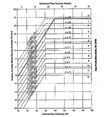
Another quality indicator was proposed in “An Algorithm for Estimating Gas Production Potential Using Digital Well Log Data, Cretaceous of North Montana”, USGS Open File Report 01-12, by T. C. Hester, 1999. It related neutron-density porosity separation and gamma ray response to production, based on the graph in Figure 12.
This graph is converted to a numerical quality indicator (Qual1) in a complex series of equations that represent predicted flow rate. An Excel and Lotus 1-2-3 spreadsheet for solving this graph is available free from the downloads page on my website at www. spec2000.net.
Hester’s paper only looked at the average quality of a laminated reservoir and did not consider the thickness of a particular quality level. To overcome this, we can use a quality

cutoff and obtain a thickness-weighted quality and correlate this to actual production, similar to a net-pay flag using porosity and saturation cutoffs:
1: IF Qual1 >= x
2: THEN PayFlagQ1 = “ON”
3: AND PayQ1 = PayQ1 + INCR
Where:
x = 4.0 or 5.0
PayQ1 = accumulated pay thickness based on Qual1>= x
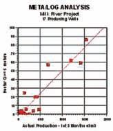
A Hester quality of 4.0 or higher reflects reservoir rock that is worth perforating, and gives similar net reservoir thickness as the previous indicators. Graphs showing the correlation of actual production to net reservoir with Qual1 >=5 and >=4 are shown in Figures 13 and 14. The regression coefficients are 0.856 and 0.837 respectively. Although this looks pretty good, the low rate data is clustered very badly and other indicators work better in low rate wells. Some of these wells were not perforated optimally and the Qual1 pay flag is helpful for workover planning.
E. R. (Ross) Crain, P.Eng. is a Consulting Petrophysicist and a Professional Engineer with over 45 years of experience in reservoir description,

petrophysical analysis, and management. He has been a specialist in the integration of well log analysis and petrophysics with geophysical, geological, engineering, and simulation phases of oil and gas exploration and exploitation, with widespread Canadian and Overseas experience.
His textbook, “Crain’s Petrophysical Handbook on CD-ROM” is widely used as a reference to practical log analysis. Mr. Crain is an Honourary Member and Past President of the Canadian Well Logging Society (CWLS), a Member of Society of Petrophysicists and Well Log Analysts (SPWLA), and a Registered Professional Engineer with Alberta Professional Engineers, Geologists and Geophysicists (APEGGA).
Correction: UNICORNS IN THE GARDEN OF GOOD AND EVIL - PART 4 – Gas Shale. The units conversion constant KV4 in the Free Gas equation on page 20 (February 2011 issue of CSPG Reservoir) was incorrect. The correct value is: KV4=0.000 043 560.
The Unconventional Reservoir Research Group in the Department of Earth and Ocean Sciences at The University of British Columbia invites applications for a Research Associate beginning as early as July 1, 2011. The appointment will be for a minimum of two years with the potential for extension based on funding availability and satisfactory performance reviews.
The position involves the investigation of reservoir properties including geomechanics of unconventional rock (shales, tight sands, coals) using a variety of testing equipment including triaxial compression testing equipment, porosity, permeability and di usion assessment using novel methodologies, adsorption and surface area analyses, electron microscopy, organic and inorganic geochemistry and organic petrology. The successful applicant is anticipated to be uent in petrophysics, reservoir modeling and geophysics. Candidates must possess a Ph.D. with specialization in geological or geophysical engineering particularly in reservoir modeling, gas sorption and ow theory and rock physics. Registration or quali cations that can lead to registration as a professional engineer in the province of British Columbia are required.
Salary will be commensurate with quali cations and experience. UBC hires on the basis of merit and is committed to employment equity. We encourage all quali ed persons to apply; however, Canadians and permanent residents of Canada will be given priority.
Applications, including a CV, copies of two relevant publications, and the names, e-mails and phone numbers of three references should be sent by May 31st, 2011 to Dr. R. Marc Bustin, Department of Earth and Ocean Sciences, The University of British Columbia, 6339 Stores Road, Vancouver, B.C. V6T 1Z4 (Phone: (604) 822-6179; Fax: (604) 822-6088).
If you want easy-to-use decision-making
– there’s only one direction to go
industry-leading customer service easy & efficient migration of existing data helping clients increase productivity
geoSCOUT™ uses a Windows-based platform that makes it easy for you to get the oil and gas data you need to make smarter decisions faster and to maximize the return on your oilfield investments. And, our solution provides you with a complete package that all your departments can use.
Thousands of landmen, engineers & geologists use geoSCOUT oil and gas mapping and analysis software every day, to make more efficient, informed decisions. Give us an hour for a demo – we know you’ll see the value. Call 403.262.1992 Email info@geoscout.com | Online www.geoscout.com
Another powerful suite of tools from


During the been on new data in the effective possible. created a powerful tool for geologists who can use our ASCII digital data to search database 14,000 from Western Canadian Basin.


Geologists can search location area - - - - etc. - formation visual porosity, grain size, rounding/sorting, fossil type, and more. will to download and depth registration own a license to, can and download online.


several this:
FREE SEARCH:
Search by location, view thumbnails and see Canstrat tops. If you can download an additional 600 meg file, you can also search by lithology and colour for no charge.
SUBSCRIPTION SEARCH:
Search using the full capability of our digital data ASCII, by location, and by all the rock properties included in Canstrat lithologs such as lithology, visual porosity, grain size, rounding/sorting, fossil type, and more. You can view logs as thumbnails and view the Canstrat tops.
SUBSCRIPTION SEARCH AND VIEW:
Search using the full capability of our digital data ASCII, by location, and by all the rock properties included in Canstrat lithologs such as lithology, visual porosity, grain size, rounding/sorting, fossil type, and more. You can view the full set of 14,000 logs as full size segments and view the Canstrat tops.


| By R. J. Spencer1,2, R. Aguilera3 , P. K. Pedersen1, C. R. Clarkson1
1Department of Geoscience, University of Calgary, 2 Alberta Innovates Technology Futures, 3Schulich School of Engineering, University of Calgary
The last part of this series, Part 10, will be published next month. In there we will reply individually to any questions our readers might have. We encourage you to submit your questions by “date”. We will also take the opportunity to publish some clarifications and an erratum for the series.
Tables comparing properties of producing reservoirs such as tables 1 and 2 from part 2 of this series and Table 1 here are used to try and determine what is needed for a successful shale gas target. There does not appear to be a clear-cut distinction among these. For instance, depths of successful reservoirs range from a few hundred to a few thousand metres. Net thickness ranges from <10 to 200 metres. Organic carbon content ranges from less than one to a few tens of percent. Porosity values also vary by an order of magnitude. Geologic and lithologic parameters from successful shale gas reservoirs vary considerably. There seems to be no consistent set of parameters that to date define a good shale gas target with any degree of certainty.
The answer to what makes a good shale gas target appears to lie in the technology available for exploitation, and whether or not that technology is suitable for the formation of interest and the conditions therein. To some extent, it appears that what makes a successful shale gas target is a successful, mature shale gas project. Hopefully this will become clearer below.
Technologic advances in shale gas exploitation have been quite rapid. Do we really understand what changes in drilling and completion practices might maximize production from a set of highly diverse reservoirs? The “optimum shale gas target” has been and is likely to continue to be a moving target because of the geologic and technical matters mentioned above. The mix of environmental issues that have surfaced during the last few years, along with potential political responses to these, are likely to influence shale gas exploitation. Market conditions and price are also paramount.
1Total
5Percent
* Data from Wang and Reed, 2009 ** Data from Aguilera, 1978
the Barnett Shale, Fort Worth Basin (FWB), United States; and Utica Shale, Quebec, Canada (Adapted from Chan et al., 2010).
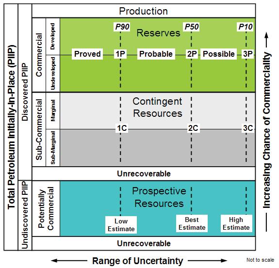
This section attempts to apply the Petroleum Resources Management System (PRMS) to shale gas reservoirs and draws heavily on previous work by Chan et al. (2010). The PRMS is endorsed by the Society of Petroleum Engineers (SPE), the World Petroleum Council (WPC), the American Association of Petroleum Geologists (AAPG), Society of Petroleum Evaluation Engineers (SPEE), and the Society of Exploration Geophysicists (SEG). A revised version of the PRMS that will include guidelines for evaluation of unconventional resources will be available to petroleum industry practitioners in the near future.
The PRMS is a project-based evaluation and must include project risk and uncertainties. Commerciality has to be confirmed before classification of the recoverable resources as reserves can be undertaken. Estimations
of recoverable resources from shale gas reservoirs must include an assessment of the associated uncertainty expressed by allocation to PRMS categories using the 1P, 2P, 3P; 1C, 2C, 3C; low/best/high methodology shown on Figure 1. Typically the evaluation process begins with estimates of original-gas in place (see part 4 of this series). Thereafter, portions of the in-place quantities that may be potentially recovered can be assessed by clearly identified development programs.
Undiscovered recoverable shale gas volumes are classed as prospective resources and are estimated assuming their discovery and future commercial development. PRMS recognizes that shale gas reservoirs may not support a flowing well test but the accumulation may be classed as ‘discovered’ based on other evidence (e.g., sampling and / or well log interpretation).
(...Continued from page 29)
Where technically feasible recovery techniques are identified but economic and / or other commercial criteria are not satisfied, even under very aggressive forecasts, estimates of recoverable quantities are classified as Contingent Resources and sub-classified as Development Not
On Production
Approved for Development
Justified for Development Development Pending Development not Viable Prospect Lead Play Development On Hold Development Unclarified
technical and commercial maturity. Reserves are only attributed after pilot programs have confirmed the technical and economic producibility and capital is allocated for development.
The PRMS approach is illustrated by comparing three North American shale gas projects at different stages of maturity. The Utica Shale in the Saint Lawrence Lowlands of Quebec is in the very early stages of study. The Barnett Shale projects in the United States are considered as mature; however, there remain major uncertainties regarding ultimate recoveries. The Fayetteville, also in the United States, is at an interim stage of maturity. The location of these three shale reservoirs is presented in of Part 1 of this series.
Viable. If the recovery processes have been confirmed as not technically feasible, the inplace volumes are classified as Discovered / Unrecoverable. As the play and technologies mature and development projects are better defined, portions of estimated volumes may be assigned to Contingent Resources sub-classes that recognize this progressive


While there are significant differences in the detailed geology and mineralogy of these shale reservoirs, there are sufficient similarities to allow careful transfer of learning regarding completion and development scenarios to make preliminary estimations of overall potential in the early stages of the Utica Shale. However, because what works well in one shale can prove to be a major fiasco in another, the technical and commercial viability for development of an unconventional resource must be f irst be demonstrated by successful pilot projects before conversion to reserves.
All data utilized in this section for illustration purposes is publicly available in the literature and on websites of companies operating in shale gas reservoirs. While the assessments are described using a deterministic approach so that they can be reproduced easily, the same method can be extended to evaluations using probabilistic methods.
Results of early attempts to quantify volumes of natural gas in the Utica shales and potential recoveries are available in the literature (Aguilera, 1978). The work was based on estimates of fracture porosity and water saturation, and the volumes of original gas-in-place (OGIP) were determined volumetrically. The work led to volumes of free gas in the fractures ranging between 5.9 and 26.6 bscf per section (640 acres). The recovery was estimated on the basis of free gas in the fractures, without considering any adsorbed gas, by assuming an abandoning pressure of 100 psi per 1,000 feet of reservoir depth. The result was estimated ultimate recoveries ranging between 4.7 and 21.4 bscf per section at an abandonment pressure of 625 psi. The initial
reservoir pressure used in the estimate was 3,000 psi.
A forecast per well was carried out by assuming some damage around the wellbore and continuous transient linear flow throughout 20 years without reaching any boundary effects. The initial average rate for the first year of production was estimated at 0.5 MMscfd based on actual testing results of vertical wells. Gas cumulative after 20 years of production was calculated to be 2.5 bscf. A preliminary analysis of a partial development project drilling 90 wells was considered to be potentially economic with only 46 successful wells required to break even. In spite of this economic evaluation the project was deemed to have a large degree of risk and a low chance of commerciality and as a result the project was put on hold.
Fast forward 33 years. We could now classify the recoverable volumes from the Utica Shale under PRMS as prospective Resources with a range of uncertainty between low and high estimates of 4.7 and 21.4 bscf per section, respectively. The project would be put on hold until sufficient wells were drilled that would allow portions to be reclassified as ‘discovered’ and thus Contingent Resources. As the Utica shales extend over 150 square miles, the potential
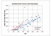
approximately the equivalent, from a gas production point of view, to a vertical well.
recoverable resources of the total play would be between a low of 711 bscf and a high of approximately 3,200 bscf.
There have been significant advances during the last few years particularly on issues related to drilling and completion of horizontal wells in shale gas formations as discussed in Part 6 of this series. These technologies have been used successfully in several shale reservoirs including, for example, the Barnett in Texas. Based on results to date, the industry has developed a useful “rule of thumb” that each hydraulic fracture stage in a horizontal well is
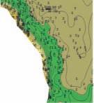
These recent innovative technologies have also been used in the Fayettville and are being investigated in the Utica shale. Figure 2 shows learning curves comparing gas production from these two shale reservoirs. There is continuous improvement with time in gas production rates in both reservoirs. The last horizontal well drilled, stimulated, and tested in the Utica shales in early 2010, the Saint Eduard No. 1A, is shown to produce gas, at the time of testing, with a rate of over 5 MMscf/d. If this rate holds at economic levels it would be reasonable to start moving some of the Utica volumes from the Prospective into the Contingent Resources class as there would be a continuous increase in the chance of commerciality. If not, additional pilots would have to be drilled.
Different operating companies utilize different evaluation methods and some put a lot of weight on adsorbed gas volumes. In Table 1, we use exactly the same methodology for consistency while comparing the Utica and Barnett shales, using publically available data. The methodology for running the calculations
(Continued on page 32...)
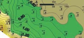

(...Continued from page 31)


Reservoir Engineering


Manage, edit, organize and analyze all your data together in one environment...

• Sophisticated multiple-function Saturation-Height modelling

• Develop in the core domain and reconcile to the log domain, or optimize directly in the log domain
• Apply saved models and export to reservoir modeling software
• QC and analyze pressure-time pre-test data
• Detect uid types, free uid levels and hydraulic zones in single or multi-well pressure-depth analysis mode

shown on Table 1 has been presented in part 4 of this series. An important objective is determining gas in place and what portion of that total volume is stored as free gas. Some of the characteristics of the Utica and Barnett shales are different, for example, the percent TOC. Others, such as free-gas porosities are considered to be of the same order of magnitude. For example, free-gas porosity for the Barnett has been estimated at 1.7% by Wang and Reed (2009). Free gas porosity for the Utica shale has been estimated at 1.4% by Aguilera (1978). Volumetric estimates of total OGIP per acre-ft are of the same order of magnitude (104.8 for the Barnett and 96.5 for the Utica). Volumetric estimates of free OGIP per acre-ft also compare reasonably well (50.9 for the Barnett and 40.9 for the Utica). Furthermore both reservoirs have readily available access to markets.
However, in spite of the above reasonable comparisons, a large part of the Barnett is assigned reserves because the ‘project base’ evaluation, including pilots, is commercial, presents relatively low risk, and has reasonably well defined production decline type curves that decrease significantly the range of uncertainty. On the other hand, the Utica is still lacking definitive results from pilot wells and clearly defined production decline curves.
Aguilera, R. 1978. Log analysis of gas-bearing fracture shales in the Saint Lawrence Lowlands of Quebec. Society of Petroleum Engineers paper 7445 presented at the SPE 53rd Annual Fall Technical Conference and Exhibition held in Houston, Texas, 1-3 October 1978.
Chan, P., Etherington, J. R., and Aguilera, R. 2010. A process to evaluate unconventional resources. Society of Petroleum Engineers paper 134602 presented at the SPE Annual Technical Conference and Exhibition held in Florence, Italy, 19-22 September 2010.


MODULES SHOWN


Wang, F. P. and Reed, R. M. 20 09. Pore networks and fluid flow in gas shales, Society of Petroleum Engineers paper 124253 presented at the SPE Annual Technical Conference and Exhibition held in New Orleans, Louisiana, 4-7 October 2009.
Websites of Some Companies Operating in Shale Gas Reservoirs (accessed in 2010): Questerre: http://www.questerre.com/en/h/en/ Southwestern Energy: http://www.swnnb.ca/ Junex: http://www.junex.ca/en/drilling/uniquecompany.php
| By John Varsek, CSPG President 2010
yearly, CSPG recognizes its most distinguished volunteer. Recipients for the President’s Award are selected by the President at the end of his term. The President’s Award is awarded for sustained and distinguished service to the Society. Past winners share the traits of providing exemplary leadership in a variety of roles and which the Society recognizes as leading models of achievement to be emulated. Many recipients have continued to contribute to the Society, its programs and events, such that this award reflects a milestone in their past and continuing excellent contributions.

Dr. Mark Cooper has already earned several of the CSPG’s most prestigious awards. This is his second President’s award, the first being bestowed in 2006. It is the first time the CSPG has honoured the same recipient twice with a President’s award. He epitomizes how our outstanding leaders continue to make a positive difference in our Society and community.
This time he is being recognized for two major accomplishments. First, for assuming the chairmanship and leadership of the GeoCanada 2010 convention in a challenging environment, when the economic and Industrial outlook was bleak. He effectively led the joint convention of Canada’s six leading geoscience Societies, including two umbrella groups representing all Canadian geoscientists. Drawing on skills that distinguished him as a business leader and employing his extensive convention experience as:
1. the CSPG technical chairperson of GeoCanada 2000,
2. the communications chair for the 2003 convention, and as
3. the co-general chair of the 2006 CSPGCSEG-CWLS convention.
Mark provided organizational and financial leadership to the GeoCanada 2010 organizing committee.
His leadership led to smart decisions, financial stability, solid program delivery, and a better than forecast financial performance that benefited both the reputation of the CSPG as Canada’s leading Geoscientific Society and all participating partners.
Mark is also being recognized for his authorship and continued updating of the Geological Highway Map of Alberta, which he first compiled and published in 2000 for the CSPG. This project is a very visible and pertinent contribution by Mark and the Society to geoscience education of the public.
Every organization needs reliable, experienced, and talented individuals who
(Continued on page 34...)


provide sensible insight and confident leadership to steer them through crises and challenges. That is why we are honouring Mark’s leadership. It is through efforts such as his that the Society continues to thrive in spite of the economic and industrial cycles. Mark’s achievement exemplifies continuous service and leadership among many Society contributions. Mark has, and I hope will continue to be, a great contributor to the Society.
Mr. Colin Yeo was CSPG president in 2007. However, he is receiving this President’s award
for sustained and influential contributions to the Society following his Presidential term. Four key contributions are being recognized.
1. Laying the foundation for rebuilding the Society. Colin provided essential continuity in advising the Executive teams of 2008, 2009, and 2010 on office restructuring, including the modernization of employment and financial policies and key staffing decisions that resulted subsequently in strong financial performance. He also advocated for a visionary, strategically focused, and active Executive like that of the past two years, which will be continued into the future.

most comprehensive, integrated laboratory services worldwide. From core analysis, sorption, geochemistry and isotopic composition to detailed basin modeling and comprehensive data packages, we provide you with real reservoir rock and fluid information that hasn’t been distilled by a simulator or iterated by software.
We call it “The Ground Truth™” – giving you the accurate answers you need for better reservoir understanding. You’ll call it a better return on your reservoir investment. To learn more, contact TheGroundTruth@weatherfordlabs.com. weatherfordlabs.com

2. Partnership development. Colin oversaw negotiation of the Joint Annual Conventions agreement with the CSEG, which is the CSPG’s first long-term partnership agreement. This beneficial and successful achievement and its learnings are paving the way for future partnerships opportunities to provide better and more exciting conventions, reliable sponsorship opportunities, and meaningful projects between our two Societies.
3. Mentoring the Executive. Colin has provided pertinent and appreciated one-onone guidance to various CSPG Directors since 2008 in the areas of Publication, Finance, Volunteer Management, and Executive performance.
4. Guiding and contributing to the expansion of the Reservoir magazine. Since 2006, Colin has influenced the expansion of technical content and contributed editorials about Executive activities and significant volunteer contributions. The Reservoir magazine today, is regarded consistently as one of the key benefits of CSPG membership. The Reservoir has become a widely read and visible anchor for the Society and a key platform for our advertisers.
In summary, Colin’s achievements are best viewed cumulatively for their impact on many aspects of Society operations and services. He keeps the future and pertinence of the Society at the forefront. He tactfully brings many issues, compelling insights, and new opportunities to the attention of the leadership. He has a rare and effective talent for which the CSPG is grateful.
Full citations for Mark Cooper and Colin Yeo appear in the March 2011 Bulletin of Canadian Petroleum Geology.
The 2010 President’s Awards will be presented at the CSPG Awards Ceremony on Monday, May 9th at the Hyatt Regency Calgary (Imperial Ballroom) starting at 6:00pm. This event is open to the public; please feel free to invite family and friends.
| By Dawn Hodgins, SIFT Chair
The Student Industry Field Trip, fondly known as “SIFT,” is the CSPG’s flagship student program where 3rd year undergrad geology students are introduced to the petroleum industry. Founded in 1978 by Bill Ayrton, the SIFT program was originally a four-day course that has now grown into an intense two-week program, which has been running for 33 years. Every year following the end of the winter school term, one student representative from each Canadian university offering a geosciences or geological engineering degree is brought to Calgary for a comprehensive introduction to the petroleum industry.
The two-week program includes a summer employment program (for interested parties), an extensive lecture series, core workshops, field trips, and a petroleum exploration game. SIFT has become successful because of the considerable support received from the petroleum industry and from the CSPG’s Educational Trust Fund each year.
The students attend a series of lectures given by industry experts on topics key to the petroleum industry, such as well logging/interpretation, carbonate/clastic reservoirs, geophysics, operations, and more. Students also participate in core workshop seminars, a four-day Rocky Mountain geological field trip, a Dinosaur Provincial Park field trip, and a rig tour.
In addition to the rigorous classroom and field work, students also participate in an exploration game that allows them to apply their newfound knowledge of geology and techniques practiced in the industry. The students are grouped into fledgling oil and gas companies and given an initial sum of money to manage and grow their company through land sale
acquisition, exploration drilling, and deal making in a designated area that simulates typical oil and gas industry activity. The trip concludes with the mock companies presenting their financial standing and geological interpretation to a panel of industry judges. Two winning teams are selected by the industry judging panel: the team with the best overall geological interpretation and the team with the highest fiscal growth (i.e., they made the most money!). The members of the two winning teams are then presented with their prestigious awards at the final StudentIndustry Wine & Cheese Mixer on the last day of the program.
In addition to all of this action, each year the SIFT committee aids students in finding summer employment for those that are interested in gaining further experience following the twoweek SIFT program. Interviews with interested companies will be scheduled just prior to the start of the official program. Many of Calgary’s oil and gas companies have used the SIFT job program to obtain talented summer students fresh from a comprehensive introduction to the petroleum industry. By hiring SIFT students, companies can save on initial training expenses, while providing the SIFT students with an opportunity to further their petroleum industry experience.
Students are selected by the SIFT committee in early March. We, the committee, inquire if the student is interested in applying for summer employment in the petroleum industry. The interested students provide the committee a cover letter, résumé, and transcripts. The SIFT Committee contacts potential summer job employers by several means to solicit positions for the SIFT program students. The students’
documents will then be forwarded to interested employers. The documents of applicants are sent out to companies at the beginning of April. Typically, each year 8-12 students participate in the program.
Interested employers should then contact Alyssa Middleton at the CSPG office (Alyssa. middleton@cspg.org or (403)513-1233) with the names of students they are interested in interviewing. We ask that potential employers provide us with their list of interview candidates by April 18th. We do not encourage companies to contact or make offers to the students prior to SIFT.
The SIFT committee Student Liaison will then arrange the interview schedule. Interviews will take place Sunday, May 1st, 2011 at the University of Calgary. Alternate interview dates may be arranged between May 1st and May 13th. Students seeking employment are flown in a day early so that the interviews do not interfere with the busy SIFT schedule. In the event of a conflict, we will try to work around your schedule. Once interviews have been completed, offers can be made to the students. We suggest that once you decide to make an offer, you do so as soon as possible, as some students may receive more than one offer. Students will be available to work from May 16th until the end of August this year.
If you are not able to find a student suitable for your available position, you are not obliged to hire one. If you have any questions or concerns, please contact Alyssa Middleton at (403) 5131233 or atAlyssa.Middleton@cspg.org.
Elbow Springs Golf Club • June 15 - 17, 2011
The Tournament would like to thank the following 2010 sponsors:
Diamond Sponsors
geoLOGIC Systems
Schlumberger of Canada
Emerald Sponsors
GeoStrata Resources Inc.
IHS Energy
Macquarie Tristone Capital Advisors
AGAT Laboratories
Athabasca Oil Sands Corp.
Baker Atlas Wireline
Belloy Petroleum Consulting
CB Securities
Divestco Inc.
Energy Navigator Inc.
Fugro Data Solutions Canada Inc.
GLJ Petroleum Consultants
Halliburton
Arcis Corporation
ATB Financial
ConocoPhillips Canada
Continental Laboratories Ltd.
Deepwell Energy Services
Devon Canada Corporation
Knowledge Energy Inc.
MD Totco Nov. Wellsite Gas Watch
Barry Rypien
Gabel Energy Inc.
Martin Quinn
Bronze
Candian Stratigraphic Services
Crow River Resources
Rock Document Services
RBC Dominion Securities
Weatherford Canada Partnership
Wildcat Scouting Services (1991) Ltd.
M J Systems
Painted Pony Petroleum Corp.
Pason Systems Corp.
ProGeo Consultants
RECON Petrotechnologies Ltd.
RPS Energy
Ryan Energy Technologies
Sproule Associates Ltd.
West Canadian
Pajak Engineering Ltd.
Petrocraft Products Ltd.
Polaris Resources Ltd.
Regent Resources Ltd.
ReSurge Ltd.
Rigsat Communications
Sample Pro Ltd.
Van Helden Agencies Ltd.
Montane Resources Ltd.
Trivision Geosystems
Hydro-Fax Resources Ltd.
San Dago Resources Ltd.
The CSPG Classic Golf Tournament has incorporated fundraising for charity as part of the event. In 2011,, the charities selected are the Salvation Army Agape Hospice and the CSPG Education Trust Fund. ,
NAME:
SPOUSE’S NAME:
COMPANY:
ADDRESS (Bus.):
Registration Form
POSTAL CODE:
TELEPHONE: CELL PHONE:
E-Mail:
All contestants are required to have a photo in the Golfer’s Photo Roster. Former contestants who have submitted a photo in the past need not do so again. Handicap / Golf Index __________________ or Average of best three 18-hole scores in past 2 years:______________
Registration Fee: Includes three rounds of golf with power cart; Paid driving range; Door prize draws; Skill prizes; BBQ (at Elbow Springs) and Awards Banquet (Calgary Petroleum Club) both for you and your guest.
Cost: Tournament Fee $428.50 GST $21.45
To assist the Entertainment Committee with budgeting, please indicate if you plan to attend the two major social events of the tournament:
Wednesday Barbecue: Self: Yes q No q
Guest: Yes q No q
Friday Awards Banquet: Self: Yes q No q Guest: Yes q No q
Social Events Cancellation or Additions require 72 hours notice before the event. Please contact Bob Earle by phone: (403) 803-3744 or email: cspgclassicgolf@gmail.com
Make Cheques Payable To: CSPG (Classic Golf)
Send Entries To: CSPG Classic Golf Tournament 600, 640-8th Avenue S.W. Calgary, AB, T2P 1G7
* Please photocopy your entry form and cheque before mailing.
Last day for refund requests: June 1, 2011.
Mail/Courier Registration: Print this registration Form (http://www.cspg.org/events/events-social-classicgolf.cfm) send to CSPG Office with cheque.
| By Aaron Grimeau and Tannis McCartney
The CSPG offered four awards, funded by the CSPG Education Trust Fund, to outstanding undergraduate students across Canada. The competition was organized by Aaron Grimeau and Sandra Rosenthal of the University Outreach Committee.
One award of $500.00 was allocated to each of four regions:
1. Atlantic Canada and Québec
2. Central/Ontario
3. Western Canada
4. Canada-wide
Of these four awards, only two were awarded this year, to Gennyne McCune of the University of Calgary and Frank Ryan of Memorial University of Newfoundland. The awards allocated for the Central/Ontario and Canada-wide regions were not awarded due to a lack of applicants.
In order to be selected for the award, the applicants needed to demonstrate an interest and talent for soft-rock geology and petroleum exploration and development, through a personal essay, a letter of recommendation from a professor, and academic standing (as evidenced by a copy of the applicant’s transcripts).
Frank Ryan is a fourth-year earth sciences
student at Memorial University. His academic interests are in reservoir characterization, hydrocarbon exploration, sedimentary diagenesis, and geophysics. Frank is currently working on an honours thesis with Dr. James MacQuaker, using a variety of methods to look for links between petrofacies and lithofacies in a shale play in northeastern British Columbia. Frank is also the pastpresident of the Alexander Murray Geological Club at Memorial University, and has interests in hockey, guitar, and volunteering in the community. He is grateful for the support of the CSPG, and looks forward to spending the summer working in industry before beginning graduate studies in the fall.
Gennyne McCune began working in the Arctic in 2008 as an assistant with the Geological Survey of Canada. She was an assistant again in 2009, but in 2010 she conducted research for her undergraduate thesis, supported by the Geomapping for Energy and Minerals (GEM) program, on Ellef Ringnes Island. Gennyne is examining the widespread occurrence of glendonites in Cretaceous shales of the Sverdrup Basin. The presence of glendonites can be an indicator of cold temperatures and specific chemical conditions often encountered in association with organic-rich sediments at high latitudes. Gennyne’s goal is to interpret
the geochemical and paleoenvironmental conditions in the Sverdrup Basin associated with glendonite occurrences, and she is looking forward to returning to the Arctic to continue this work.
Congratulations to both Gennyne and Frank for winning the 2010/2011 CSPG Undergraduate Awards, and thank you for your contributions to this article. Application deadlines for next year will be in late January again to give students time to apply. We hope to see an increased number of applicants for the 2011/2012 academic year such that we can give out all the awards.
If you have been a member of CSPG for over 30 years (since 1981) and have not yet received your invitation please contact kasandra klein, kklein@cspg.org or 403.513.1229.
Deterministic and Stochastic Inversion developed by Earthworks
Earthworks Seismic Inversion plug-in for Petrel* is an ultra-fast full featured seismic inversion software enabling effective use of impedance data and AVO in the reservoir modeling workflow.
• Fully integrated into Petrel
• Inversion of pre- and post stack seismic data
• Several optional algorithms for both deterministic and stochastic inversion
• Functionality for inspecting results and better understand the geophysical uncertainty in reservoir modeling


Eighteenth green, five-foot uphill putt with a slight break to the right. IfÉ.. noÉ. when I sink this putt, I will claim the CSPG Classic trophy for my flight, and bragging rights for the next year.
Eighteenth green, five-foot uphill putt with a slight break to the right. If….. no…. when I sink this putt, I will claim the CSPG Classic trophy for my flight, and bragging rights for the next year.
Every professional level, every skill level, and every geo-discipline is welcome at this tournament. Men, women, senior, and junior…we want everyone to come and have fun!
Are oil and gas deals consummated with on the course like on a Hollywood movie? No, however, in Calgary, golf is a big part of the oil & gas industry and the oil & gas industry is big into golf. Our industry is about people, process and plays. The plays and process may change as we have witnessed with the harvesting practice of resource type plays, but it is the people driving the ideas that make our industry thrive.
Are oil and gas deals consummated on the course like on a Hollywood movie? No, however, in Calgary, golf is a big part of the oil and gas industry and the oil and gas industry is big into golf. Our industry is about people, process, and plays. The plays and process may change as we have witnessed with the harvesting practice of resource-type plays, but it is the people driving the ideas that make our industry thrive.
Yes, we can always socialize via BlackBerry, Facebook or LinkedIn. More effectively though, we can step onto a golf course and engage in face-to-face social networking with the professionals who are involved in the latest plays, technologies and financing structures during an extended game of golf. Here you can leave the rock hammer in the bag and pull out the nine-iron!
On June 15, 16 and 17th, 2011, the CSPG will host the 51st Annual CSPG Classic Golf Tournament at Elbow Springs Golf and Country Club in Calgary. There will be 144 geologists and geophysicists and associated industry service companies networking while enjoying three rounds of golf. Here at the Classic, business contacts are made and friendships maintained.
The CSPG Classic is designed to match participants with similar skill level into groups to insure that everyone has a chance to win. As such, you can find a newgrad golfing with a VP of exploration, the owner of a successful service company, or the person you’ve been dealing with for a year but have never met. The purpose of the Classic is to share time with colleagues, forge some partnerships, and maybe even a few friendships. We’re all in this business together!
The CSPG Classic Golf Tournament is unique in that includes three rounds of golf over three days in addition to on-course sponsor tents with refreshments and food, a Friday breakfast and three evening dinners including the awards banquet and dance on Friday at the Petroleum Club which is always an entertaining end to this wonderful event. The tournament features over $10,000 in prizes and draws including vacation trips, a Bar-B-Q draw and daily hole and skill prizes.
yes, we can always socialize via BlackBerry, Facebook, or LinkedIn. More effectively though, we can step onto a golf course and engage in face-to-face social networking with the professionals who are involved in the latest plays, technologies, and financing structures during an extended game of golf. Here you can leave the rock hammer in the bag and pull out the nine-iron!
The 2011 CSPG Classic welcomes returning charity partner AGAPE Hospice, as well as the CSPG Educational Trust Fund, who will benefit from special events during the tournament.
Every professional level, every skill level and every geo-discipline is welcome at this tournament. Men, women, senior and juniorÉwe want everyone to come and have fun!
The CSPG Classic is designed to match participants with similar skill level into groups to insure that everyone has a chance to win As such, you can find a new-grad golfing with a VP of exploration, the owner of a successful service company or the person youÕve been dealing with for a year but have never met. The purpose of the Classic is to share time with colleagues, forge some partnerships and maybe even a few friendships. WeÕre all in this business together!
So grab your nine-iron and register early at the CSPG website, and come out and share this opportunity to expand your network…with a nine-iron. Questions can be directed to cspgclassicgolf@gmail.com.
The 2011 CSPG Classic welcomes returning charity partner AGAPE Hospice as well as the CSPG Educational Trust Fund who will benefit from special events during the tournament.
Sincerely,
So grab your nine-iron and register early at the CSPG website and come out and share this opportunity to expand your networkÉwith a nine-iron. Questions can be directed to cspgclassicgolf@gmail.com


Sincerely,
Mike LaBerge Chairman CSPG Classic Golf Committee
On June 15, 16, and 17th, 2011, the CSPG will host the 51st Annual CSPG Classic Golf Tournament at Elbow Springs Golf and Country Club in Calgary. There will be 144 geologists and geophysicists and associated industry service companies networking, while enjoying three rounds of golf. Here at the Classic, business contacts are made and friendships maintained.
The CSPG Classic Golf Tournament is unique in that includes three rounds of golf over three days in addition to on-course sponsor tents with refreshments and food, a Friday breakfast and three evening dinners, including the awards banquet and dance on Friday at the Petroleum Club, which is always an entertaining end to this wonderful event. The tournament features over $10,000 in prizes and draws, including vacation trips, a Bar-B-Q draw, and daily hole and skill prizes.

Mike LaBerge Chairman CSPG Classic Golf Committee

| By Tom Sneddon, P.Geol., Manager of Geoscience Affairs, APEGGA Calgary
For as long as I can remember, field hands have called us “Geo’s”. It didn’t matter whether it was a diamond-drilling crew or a seismic crew; it was a common bit of verbal shorthand. I always bore the title proudly because it amply described what I did for a living. Being one of those borderline geophysicist/geologist types, it was always a nuisance to have to tell people what I wasn’t and “Geo” covered the turf quite nicely.
On February 23, 2011 the Alberta Legislature gave Bill 3 - ENGINEERING, GEOLOGICAL AND GEOPH y SICAL PROFESSIONS AMENDMENT ACT, 2011 (the “Amendment Act”) first reading. When the bill finally makes it through the legislative process to Proclamation, the title “Professional Geoscientist” will be joining “Professional Geologist” and “Professional Geophysicist” as legal titles in Alberta for those people who the APEGGA Board of Examiners deem qualified to bear them.
For those who choose to adopt the new title (it will be optional for those practitioners who already hold the latter two titles), “P.Geo.” will take up less real estate on your business card, but will make no other
change to your ways of doing things. If you want to change your scope of practice from geology to geophysics, you still need to qualify as a geophysicist with the academics and experience requirements necessary to work in that field.
New entrants into geoscience will be granted exclusive use of the Professional Geoscientist title. Professional Geologist and Professional Geophysicist will be phased out as the current crop of practitioners who hold them leaves the professions.
The primary motivator for the change is the set of obligations imposed on Alberta citizens by the Canada-wide agreement on Internal Trade; the prairie regional New West Partnership Agreement; and the Trade, Investment and Labour Agreement between Alberta and British Columbia. All other jurisdictions in Canada recognize the Professional Geoscientist label as being parallel to the Professional Engineer title we are all familiar with. There is less intellectual distance between the geoscience disciplines than there is between, say, civil engineering and computer engineering. A side benefit of this is that those of us who are registered in
more than one jurisdiction will save business card and letterhead space by dropping the “P.Geol. (Alberta)” from the list of credentials we display.
The secondary motivator has to do with the convergence between Geology and Geophysics thanks, in part, to the extensive use of reservoir/ore body modelling and other interpretive software in geoscience. The thoroughly modern geoscientist must have a greater grasp of basic sciences and mathematics than ever before. To understand the modelling (even contouring) programs that are in common use, one must be able to interpret the algorithms used in the programs; the geostatistics behind them and the computer implementation of those algorithms. This goes equally for the increasingly more sophisticated seismic interpretation packages and the processing steps that were involved in creation of the interpretation datasets. The practical requirements for geology are beginning to look a lot more like geophysics than ever before.
An outcome of the change in corporate title, APEGGA has chosen to do a “soft
(Continued
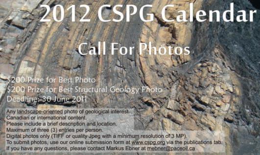
conversion” of its corporate image. That means the logo stays the same, but the name of the organization will change to the Association of Professional Engineers and Geoscientists of Alberta” (APEGA) immediately following proclamation of the revised Act. The name of the Act will change to the “Engineering and Geoscience Professions Act”; newly graduated members will become Geoscientists-in-Training; and collectively we will be called “geoscientists” in all communications, no matter what our sheepskins say. The first tentative steps in this direction occurred when the new APEGGA magazine appeared under the masthead of “The PEG” in 2010.
Reading the Amendment Act isn’t easy, as there are a lot of “struck outs and replaced bys” in its verbiage, but going through it is definitely worth your time.
The most significant change is the definition of “Geoscience” in the act, replacing the practice of Geology and the practice of Geophysics with a more general definition:
3(r) “practice of geoscience” means
(i) reporting, advising, evaluating, interpreting, processing, geoscientific surveying, exploring, classifying reserves or examining related to any activity
(A) that relates to the earth sciences or the environment,
(B) that is aimed at the discovery or development of oil, natural gas, coal, metallic or non-metallic minerals, precious stones, other natural resources or water or that is aimed at the investigation of surface or subsurface conditions of the earth, and
(C) that requires, in that reporting, advising, evaluating, interpreting, processing, geoscientific surveying, exploring, classifying reserves or examining, the professional application of the principles of mathematics, chemistry, physics or biology through the application of the principles of geoscience, or (ii) teaching geoscience at a university;
And also the definition of Professional Geoscientist:
(w) “professional geoscientist” means an individual who holds a certificate of registration to engage in the practice of geoscience under this Act but does not include:
(i) a professional licensee (geoscience), or (ii) a professional technologist as defined in section 86.4(m);
The Act will also define the exclusive scope of geoscience:
Exclusive scope of the practice of geoscience
5(1) Subject to subsection (2), no individual, corporation, partnership or other entity, except a professional geoscientist, a licensee so authorized in the licensee’s licence or a permit holder so authorized in the permit, shall engage in the practice of geoscience.
(2) Subsection (1) does not apply to the following:
(a) a person engaged in the execution or supervision of the construction, maintenance, operation or inspection of any geoscientific investigation, process, system, study, work or instrumentation in the capacity of contractor, superintendent, foreman or inspector, or in any similar capacity, when the investigation, process, system, study, work or instrumentation has been designed by, and the execution or supervision is being carried out under the supervision and control of, a professional geoscientist or licensee;
(b) a person engaged in the practice of geoscience as a geoscientist-in-training or geoscience technologist in the course of being employed or engaged and supervised and controlled by a professional geoscientist, licensee or permit holder;
(c) a person who, as a prospector, is engaged in any activities that are normally associated with the business of prospecting;
(d) a member of the Canadian Forces while actually employed on duty with the Forces;
(e) a person engaged in conducting a routine geoscientific survey or preparing a routine geoscientific report where the specifications and standards for the survey or report have been prepared or approved by a professional geoscientist or licensee;
(f) a person engaged in the routine reduction or plotting of geoscientific data under the supervision and control of professional geoscientist or licensee;
(g) a person engaged in the routine operation, maintenance or repair of geoscience equipment or facilities;
(h) a person engaged or employed by a university whose practice of the
profession consists exclusively of teaching geoscience at the university.
There is a significant number of other places in the amendment that replaces “Geologist” and “Geophysicist” with “Geoscientist”, in particular in defining the exclusive right to title. Readers are advised to visit the Legislature website:
http://www.assembly.ab.ca/IS y S/ LADDAR_files/docs/bills/bill/legislature_27/ session_4/20110222_bill-003.pdf
and review the changes directly. This is critically important if you are not currently an APEGGA member, but are interested in joining and it hasn’t been clear which category of member you should apply for. This has been an issue for people working at the higher end of the geophysical industry, in new areas of practice where engineering and geoscience collide, and in the well logging industry.
The final motivation for making the change is to allow APEGA to participate in Geoscientists Canada National Professional Geoscience public communications initiatives. The wording of the EGGP Act made such participation legally “iffy” and APEGGA lost an opportunity to address the entire nation on a couple of occasions as a consequence.
The Amendment Act also deals with crossreferences between other Alberta Acts that make mention of the name of the Act, a need for authentication of documents,0 or responsibilities of professional geoscientists, such as under the Alberta Water Act and the Fair Trading Act.
While the Amendment Act does not make for exciting reading, it is important that everyone exchanging geoscience advice for money should be aware of the changes. The Law of Unintended Effects applies every time a new act appears and an old one is amended. Some of the nuances of meaning in the context of an individual practice, for instance, may not have come to the attention of the legislative drafting committees. If you find any of these, please document them and bring them to the attention of the Executive Director (soon to be Chief Executive Officer) of APEGGA (soon to become APEGA).
If you have any questions concerning the revisions to the Act, please direct them to me and I will ensure you get a speedy response. Specifically, e-mail your questions to tsneddon@apegga.org or call me at (403) 262-7714.

Would you like to learn more about sponsor opportunities with the CSPG?
Please contact sponsor@cspg.org for more information

PROGRAM SPONSORSHIP
Technical Luncheons
Technical Luncheon Web Casting Program
Technical Divisions
Technical Divisions Bag Lunch Assist
NETWORKING EVENT SPONSORSHIP
10K Road Race & 5K Fun Run
Mixed Golf Tournament
Squash Tournament
CSPG Classic Golf
OUTREACH SPONSORSHIP
Student Industry Field Trip (SIFT)
University Lecturer Program
Student eMembership
Honorary Address
CONTINUING EDUCATION
Development of Short Courses
Development of Field Seminars
On-Going Field Seminars and Short Courses
CONFERENCE SPONSORSHIP
Conference Naming Rights
International Core Conference Gussow Geoscience Conference
ADDITIONAL SPONSORSHIP
Digital Atlas
CSPG Rocks! DVD Series
Custom Sponsorship
General Corporate Sponsorship
| By Philip Benham and Yingchun Guan
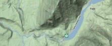


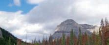
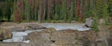
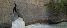
Trailhead: From Hwy 1 in yoho NP, drive 1.6 km SW of Field townsite and turn west on the Emerald Lake Road. The first outcrops of heavily deformed Chancellor occur several hundred metres in on the right. The Natural Bridge parking lot is 1.5 km from the highway.
Distance: Natural Bridge has a paved viewing trail, no more than 200m return. It provides numerous perspectives of the waterfall. Elevation gain is less than 10m. Other views can be gained upstream from short unmarked, unpaved trails at the parking lot. Careful of traffic if viewing road cuts.
The Chancellor Formation is a thick package of argillaceous limestone, slate, and calcareous shale that spans the Middle and Upper Cambrian. It is the basinal equivalent of the Mount Whyte to Sullivan formations of the Cambrian carbonate platform to the east. The edge of the platform is a high-relief feature known as the Cathedral Escarpment. The Burgess Shale fauna are preserved in proximity to this escarpment. The Chancellor strata were deposited as chaotic slumps, thin-bedded turbidites, and quiet sediment “rain” in deep water. The sediment has subsequently been metamorphosed to slate, with a cleavage oblique to and obscuring the original bedding.
At the first outcrops on your right, several 100m from the turnoff, you will note the Chancellor Formation is heavily deformed. Look for a series of short, sub-parallel sigmoidal veins filled with white calcite. These “en echelon” fractures filled with cement as the rock was sheared during deformation.
At Natural Bridge viewpoint, the Chancellor strata is deformed into several folds and the bridge itself is comprised of a tight syncline. Natural Bridge was once a waterfall, but over thousands of years, the kickinghorse River exploited structural weaknesses created by the deformation. The force of the water, countless impacts of transported pebbles and repeated seasonal freeze-thaws opened a path along fractures, or perhaps slaty cleavage, in the Chancellor. In the fullness of time, the bridge will erode and collapse, but for now we have a spectacular scene to observe.
If you wander on the rocks upstream of the bridge, you will see the alternating shaly and calcareous layers exhibiting differential erosion. There are also different deformation behaviours in the more carbonate-rich intervals. Look for varying amounts of folding, slaty cleavage, and short-distance slip surfaces. Stay clear of the raging torrents!
Reference: Balkwill, H.R., Price, R.A., Cook, D.G. and Mountjoy, E.W. 1979. GSC Map 1496A. (Terrain map from http://maps.google.com).
The Reservoir Committee welcomes contributions from our readership to this series. If you wish to offer a submission to Go Take a Hike on your favourite hike of geological interest, email the Reservoir at caitlin.young@cspg.org for more information.


by Astrid
Tightly folded Cathedral strata running perpendicular to the flow of the Kickinghorse River. Arrows mark the axis of the syncline, bedding surface marked with white line.

Thin-bedded “basinal” turbidites of the Chancellor are obvious in this roadside exposure. Mt. Stephen in background contains the thick platform carbonates of the Cathedral (CA) and Eldon (EL) sandwiching the thin “Stephen Shale” (SS). The Cathedral escarpment lays between the two locations.

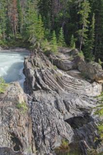
Below Left : Close-up of Natural Bridge and churning waters of the Kickinghorse River. The linear and parallel nature of the erosional niches (marked by white lines) suggest that a structural influence such as minor offsets in the tight fold, has created zones of weakness.
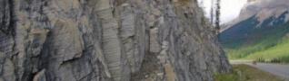
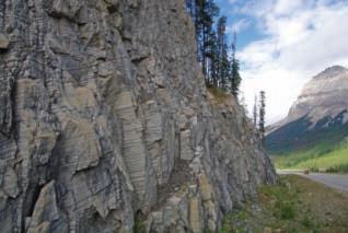
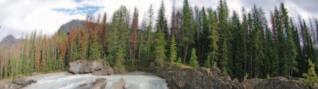

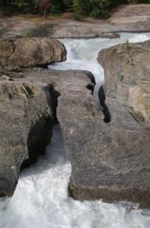
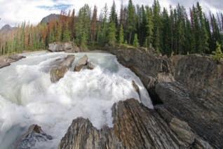
Below Right: Close-up of calcite-filled fracture systems in zones where the Cathedral strata has undergone ductile shear. These outcrops exhibit en echelon fracture systems and more complex patterns where the deformation is more intense. In some cases (circled) en echelon fracture systems have been completely sheared through, offset, and the slip surface infilled by calcite.
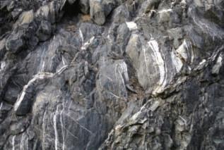
Wellsite Geological Supervision
*Conventional Wells-Heavy Oil/SAGD


*Domestic & International Supervision 906, 505 6 St. SW Calgary, AB T2P-1X5

*On & Offshore Geological Supervision

FARHATHYDERI,P.Geol President 226CopperfieldBlvd.S.E. Calgary,ABT2Z4R6 Tel 4037260666 Fax4034515380 Cell4038192516 farhat@sableconsultants.com SABLECONSULTANTS.COM

DougDauphinee,B.Sc.(Geol)
226CopperfieldBlvd.S.E. Calgary,ABT2Z4R6
Tel 4037260666 Fax4034515380 Cell4038150159
doug@sableconsultants.com SABLECONSULTANTS.COM
MONDAY AM Horn River McMurray CCS Time Lapse
MONDAY PM Horn River McMurray Water Near Surface Geophysics and Electromagnetics
TUESDAY AM Horn River Economic Recovery Conventional Western Canada Imaging and Fracture Analysis
TUESDAY PM Horn River Economic Recovery Tight Oil Grand Rapids/ Clearwater/ Carbonates
WEDNESDAY AM Horn River Eastern Canada Unconventional and Conventional
WEDNESDAY PM Basin Analysis and Sequence Strat International Shale Gas
Energy. Environment. Economy. May 9 – 13, 2011
Oil International Conventional
Oil Carbonate Sedimentology
Never before has there been so much to offer from the Technical Program! With the recession years of 2008 and 2009 in the rearview mirror and the turn-around year of 2010 just ending, the upcoming 2011 season is poised to see continued recovery in exploration, drilling activity, production, and finances of most companies in both conventional oil and gas plays, unconventional tight sandstone oil and gas, shale oil and gas, heavy oil, and oilsands. All this “re-born” activity will continue to see companies involved in a large number of plays in Canada and internationally.
FOR A MORE DETAILED LISITING OF SPEAKERS AND TALK TITLES, PLEASE VISIT WWW.GEOCONVENTION.COM/CONFERENCE/TECHNICAL-PROGRAM
May 9 - 13, 2011
MONDAY AM Clastic Sedimentology
MONDAY PM Clastic Sedimentology
6
Microseismic Processing Advances in Geosciences Seismic Acquisition
Microseismic Processing Advances in Geosciences
TUESDAY AM Caprock Integrity Arctic Seismic Processing 1 Reservoir Characterization
TUESDAY PM Montney Arctic Seismic Processing 2 Reservoir Characterization
WEDNESDAY AM Montney Microseismic Seismic Processing 3 Geomodelling
WEDNESDAY PM Montney Microseismic Seismic Processing 4 Geohazard Detection and Unplanned Challenges
The recovery 2011 technical program is designed to have a number of discussions on the several types of plays by introducing integrated sessions that allow the analysis of each play from the exploration phase to drilling, reservoir characterization, and field development. Each integrated session will deal with how seismic and non-seismic geophysics allows the mapping of the play; how geology is used to map, model, and exploit the resource; how petrophysical log and core analysis help determine producibility and deliverability of each zone; and how reservoir engineers make performance predictions. There will be talks on energy, environment, and economic recovery.
FOR A MORE DETAILED LISITING OF SPEAKERS AND TALK TITLES, PLEASE VISIT WWW.GEOCONVENTION.COM/CONFERENCE/TECHNICAL-PROGRAM


This year, the Core Conference is entitled ‘Back to the Rocks’. Submit your abstract for consideration.
Dates: Thursday, May 12, 2011 8:00 AM - 4:00 PM Friday, May 13, 2011 8:00 AM - 3:00 PM (presentations) Core Meltdown 3:00 PM - 7:00PM
Location: ERCB Core Research Facility 3545 Research Way N.W. Calgary
Cost: Attendance to the core conference is included with your convention registration. If you wish to only attend the core conference, the registration fee is $125.00.
Tickets to the annual Core Meltdown are $15.00 and can be purchased when you register to attend.
This two-day core conference will be held at the ERCB Core Research Centre, the world’s largest and most functional facility of its kind. The core conference will showcase up to 20 integrated core and poster displays and will be focused on: conventional hydrocarbon systems unconventional hydrocarbon systems, including shale gas and oil sands environmental special session: aquifer protection, water source and disposal
As in the past, the core conference will continue to include displays ranging from conventional to unconventional exploration, updating and presenting new insights into understanding the rocks. In keeping with environmental awareness and sustainable growth, water source, disposal, and aquifer protection will be offered as part of a special session. The popular Core Meltdown provides the opportunity to meet up and network with your colleagues and friends.
Sponsored by
Core on table with posters behind on the board
Scheduled PowerPoint presentation in the lecture room and meet with people at the core table
Extended abstracts (4 pages) for the Core Conference
Booklet
Please contact one of the session chairs for more clarification or if you need assistance.
Rudy Strobl Khalis Ahmed Arman Sunaryo Statoil Canada Ltd Norwest Corporation Statoil Canada Ltd. P: 403-513-1159 P: 403-399-5271 P: 403-206-1685 rudstr@statoil.com khalis@telus.net armsu@statoil.com
Please note that public parking at the ERCB is extremely limited and pay-only. Public transit is affordable and quick, and the walk from the Brentwood C-Train station will take approximately eight minutes. Walking directions are below:
Head northwest towards 33rd St.
Slight left at Research Road NW
Turn left at 33rd St. NW
Turn right at Research Way NW
Thursday and Friday, May 12 and 13
ERCB Core Research Centre 11:30 AM – 1:00 PM
Take a break from the Core Conference and enjoy a BBQ lunch at the tents behind the ERCB Core Research Centre. This lunch is free to attend with your core conference registration.
As of March 7, 2011. Subject to change.
As of March 7, 2011. Subject to change.

Company Name
Number
Aarhus Geophysics APS (www.aarhusgeo.com) 647
acQuire (www.aquire.com.au) 611
AGAT Laboratories (www.agatlabs.com) 527
Alberta Geological Survey (www.ags.gov.ab.ca) 546
ALT - Advanced Logic Technology (www.alt.lu) 630
American Association of Petroleum Geologists (www.aapg.org) 642
Apache (www.apachecorp.com)*
Apoterra Seismic Processing Ltd. (www.apoterra.com) 311
Associated Geosciences 447
Association of Professional Engineers, Geologists and Geophysicists of Alberta, The (www.apegga.org) 645
Associated Geosciences Ltd. (www.associatedgeosciences.ca)
Baker Hughes (www.bakerhughes.com) 325
Beicip Inc. (www.beicip.com) 505
Bella Vista Properties Ltd. (www.bellavistaltd.com) 810
Blueback Reservoir (www.blueback-reservoir.com) 204
Burgess Shale Geoscience Foundation, The (www.burgess-shale.bc.ca)*
Calgary Rock & Materials Services Inc. (www.calgaryrock.ca) 712
Canadian Discovery Ltd. (www.canadiandiscovery.com) 808
Canadian Society for Unconventional Gas (www.csug.ca)*
Canmore Museum and Geoscience Centre (www.cmags.org)*
Canadian Stratigraphic Services (2000) Ltd. (www.canstrat.com) 311
Canadian Space Agency (www.asc-csa.gc.ca/eng/default.asp)*
CGGVeritas (www.cggveritas.com) 316
Collaborgate Computing Solutions (www.collaborgate.ca) 433
Continental Laboratories (www.continental-labs.ab.ca) 145
Core Laboratories Canada Ltd. (www.corelab.com) 517
CREWES, University of Calgary (www.crewes.org) 104
Crowsnest Pass Ecomuseum Trust Society, Bellevue Underground Mine (www.bellevueundergroundmine.org)*
CSEG Foundation (www.cseg.ca)*
Datacon Core Imaging (www.dataconimaging.com) 547
Devon Canada (www.devonenergy.com)*
dGB Earth Sciences (www.dgbes.com) 627
Divestco (www.divestco.com) 139
Earth Sciences Museum, University of Waterloo (www.earth.uwaterloo.ca/outreach/museum)* Encana (www.encana.com)*
ESG Solutions (www.esgsolutions.com) 417
FairfieldNodal (www.fairfieldnodal.com) 126
Fugro Group of Companies (www.fugro.com) 123
GEDCO (www.gedco.com) 211
GeoEdges Inc. (www.geoedges.com) 147
geoLOGIC systems ltd. (www.geologic.com) 117
Geomodeling Technology Corp. (www.geomodeling.com) 601
Geosocket Information Inc. (www.geosocket.com) 620
Geostation Corporation (www.geostation.com) 445
Geotech Ltd. (www.geotech.ca) 622
Gore (www.gore.com) 241
Government of Alberta, Alberta Environment (www.environment.gov.ab.ca) * Government of Nunavut (www.gov.nv.ca) 812
Green Imaging Technologies (www.greenimaging.com) 246
Green’s Rock and Lapidary Ltd. (www.greenslapidary.com) 307
Geological Rentals & Services Inc. (www.grsi.ca) 700
Horizontal Solutions Intl. (www.horizontalsi.com) 346
Hydrocarbon Data System (www.hds-log.com) 144
IHS (www.ihs.com) 332
IKON Science Ltd. (www.ikonscience.com) 245
Ingrain (www.ingrainrocks.com) 800
INOVA Geophysical (www.inovageo.com) 339
Ion Geophysical Corporation (www.iongeo.com) 507
iSys - The Imaging Systems Group Inc. (www.isys-group.com) 105
Komarevich Originals Ltd. (www.komarevichoriginals.com) 623
Little Rock Document Service Ltd. (www.littlerock.ca) 305
LMKR GeoGraphix (www.geographix.com) 714
Company Name Booth Number
Manitoba Innovation, Energy and Mines, Mineral Resources Division (www.manitoba.ca/minerals) 816
Maxxam Analytics (www.maxxam.ca) 344
MEG Energy (www.megenergy.com)*
MicroSeismic Inc. (www.microseismic.com) 205
Mitcham Industries Inc. (www.mitchamindustries.com) 618
MJ Systems (www.mjlogs.com) 521
Neuralog (www.neuralog.com) 531
Newfoundland and Labrador (www.gov.nl.ca/nr) 633
Nikon Canada Inc. – Instrument Division (www.nikoninstruments.com) 404
Northwest Territories Geoscience Office (www.nwtgeoscience.ca) 820
Norwest Corporation (www.norwestcorp.com) 802
Oce-Canada Inc. (www.en.oce.ca) 338
Olympic Seismic Ltd. (www.olysei.com) 439
Olympus Canada Inc. (www.olympuscanada.com) 544
Ontario Oil, Gas & Salt Resource Library (www.ogsrlibrary.com) 644
Ontario Geological Survey (www.mndmf.gov.on.ca/mines/ogs) 646
OYO Geo Space Canada Ltd. (www.oyogeospace.com) 425
Packer’s Plus Energy Services Inc. (www.packersplus.com) 706
Paradigm (www.pdgm.com) 431
Parks Canada (www.pc.gc.ca/yoho)
Pason Systems Corp. (www.pason.com) 406
PDAC Mining Matters (www.pdac.ca/miningmatters)*
Petrocraft Products Inc. (www.petrocraft.ab.ca) 545
Petro-Explorers Inc. (www.petroexplorers.com) 629
Petrosys Canada Inc. (www.petrosys.com.au) 539
Pinnacle – a Halliburton Company (www.pinntech.com) 609
Pro Geo Consultants (www.progeoconsultants.com) 239
Quality Microscopes Ltd. (www.doughayden.ca) 806
Roxar (www.roxar.com) 140
Royal Astronomical Society of Canada (www.calgary.rasc.ca) * RPS Energy (www.rpsgroup.com) 111
SAIT Polytechnic (www.sait.ca) 606
Sample Pro Ltd. (www.samplepro.ca) 244
Saskatchewan Ministry of Energy and Resources (www.er.gov.sk.ca) 814
Saudi Aramco (www.aramco.jobs/google) 405
Schlumberger (www.slb.com) 132
SDI (System Development Inc.) (www.sdicgm.com) 524
Seismic Micro-Technology (www.seismicmirco.com) 345
SeisWare International Inc. (www.seisware.com) 411
Sigma Explorations Inc. (www.sigmaex.com) 311
SGS Canada Inc. (www.sgs.com) 130
Society of Exploration Geophysicists (www.seg.org) 643
TECTERRA Inc. (www.tecterra.com) 704
Terraplus Inc. (www.terraplus.ca) 632
TETRALE Inc. (www.tesseral-geo.com) 434
TGS (www.tgsnopec.com) 543
Total Gas Detection Ltd. (www.totalgas.ca)
702
Transform Software & Services Inc. (www.transformsw.com) 612
Trivision Geosystems Ltd. (www.powerlogger.com) 710
University of Calgary, Department of Geoscience (www.ucalgary.ca/geoscience)*
Weatherford Canada (www.weatherford.com)
112
Wellsight Systems Inc. (www.wellsight.com) 804
Yukon Government - Oil & Gas Resources (www.yukonoilandgas.com) 818
Please visit the following booths located outside of the MacLeod Halls: American Geological Institute (www.agiweb.org)
Canadian Federation of Earth Sciences (www.geoscience.ca)
Canadian Society of Exploration Geophysicists (www.cseg.org)
Canadian Society of Petroleum Geologists (www.cspg.org)
Canadian Well Logging Society (www.cwls.org)
*denotes Earth Science for Society (ESfS) exhibitor
As of March 7, 2011. Subject to change.
Monday, May 9, 2011
Calgary TELUS Convention Center – Exhibit Hall
4:00 PM – 6:00 PM
Free to attend with your convention or exhibition badge
Join us for the Monday Night Icebreaker on the exhibition floor.
Mingle with convention delegates, exhibitors, visitors, and potential clients! Additional tickets are available for purchase when you register to attend.
Monday, May 9, 2011
Centini Restaurant and Lounge
6:00 PM – 8:00 PM
Purchase your ticket to this year’s convention after-party. Continue mingling with delegates, exhibitors, and potential clients while enjoying a beverage and snacks. This event will sell-out, so ensure you purchase your ticket when you register to attend.
Tickets are $15.00 each
Tuesday, May 10, 2011
Hyatt Regency Imperial Ballroom
5:00 PM – 8:00 PM
Enjoy some food, drinks, and entertainment at this year’s networking reception taking place at the Hyatt Regency Hotel in Calgary. Give your support to charity and participate in this year’s silent auction in support of Light Up the World and possibly walk away with some amazing items!
The reception is free to attend with your delegate or exhibitor badge. Additional tickets are available for purchase when you register to attend.
Friday, May 13, 2011
Tents at the Geological Survey of Canada Parking Lot
3:00 PM – 7:00 PM
Sponsored by

Celebrate the close of another successful convention at the popular Core Meltdown event. Join the Convention Organizing Committee, fellow delegates, and exhibitors for some food, drinks, and fun.
Tickets are $15.00 each
For more information about the Core Conference and the ERCB and GSC, please visit www.geoconvention.com
Sunday May 8 – Tuesday May 10, 2011
Calgary TELUS Convention Centre (MacLeod E1-E4)
Visit interactive hands-on exhibits at four pavilions, each with a different focus on Earth Science: Resources and You, Energy for Us, One Dynamic Earth, and Our Future!
Earth Science for Society Exhibition is open to the public. Admission is FREE.
Over 2,400 students will have the opportunity to spend about 90 minutes on the exhibition floor to visit each of the pavilions.
Earth Science for Society is the public outreach program of the annual CSEG, CSPG, and CWLS geoscience convention, recovery 2011. For more information, please visit www. geoconvention.com/earth-science-for-society
Additional tickets for all special events can be purchased when you register to attend online. ,

Courses include:
❍ Fundamentals of Petroleum Geoscience—Bend
❍ Fundamentals of Siliciclastic Sequence Stratigraphy—Holbrook
❍ Getting Started in Fluvial Stratigraphy—Holbrook
❍ Creativity in Petroleum Exploration—Beaumont & Strickland
❍ Using Well Log Analysis for Reservoir Volumetrics—Erickson
❍ Practical Oil-field Development: Important Applications of Geol. & Petrol. Engineering—Erickson
❑ Computer Mapping for Petroleum Exploration—Leetaru
❑ Hydraulic Fracturing for Geologists—LaFollette
❑ Reservoir Engineering for Petroleum Geologists—Green
◆ Applied Seismic Geomorphology & Seismic Stratigraphy—Posamentier
◆ Seismic Amplitude Interpretation—Hilterman
◆ Understanding Seismic Anisotropy—Thomsen
Hosted by the Norris Conference Center:
304 Houston St. Ft. Worth, TX 76102
Phone: 817-289-2400
Fax: 817-289-2411
Special AAPG group rates at nearby hotels.
Registration and information:
Toll-free (U.S. and Canada) 888-338-3387, or 918-560-2650
Fax: 918-560-2678
E-mail: educate@aapg.org
Download a registration form at: www.aapg.org/education/sec.cfm
By Mike B. Rogers
Have you ever been asked by your family “Mom (or Dad), what do you do all day”?
Well this year, at the annual convention, you can bring them down to the TELUS Convention Centre and show them a bit of the excitement of being an earth scientist.
Earth Science for Society (ESfS) is a vibrant showcase of the earth sciences with hands-on activities and dynamic demonstrations for people of all ages and interests. It was such a huge success in 2010 that it will be held again this year, as part of the convention recovery 2011. Admission is FREE to this dynamic and interactive geosciences exhibition. It will be open to the public on Sunday, May 8th from 12-5 pm and also on Monday and Tuesday, May 9th and 10th, from 9-3:30.
As the Sunday is Mother’s Day, we will be featuring complimentary giveaways, including a crave cupcake coupon for the first 100 moms, family day passes to the Tyrell Museum, dinner, and a musical theatre package.
Highlights this year include a gold-panning adventure with “Yukon Dan,” and “The Great Trilobite Hunt” presented by the Burgess Shale Geoscience Foundation and Parks Canada.
The objective of Earth Science for Society is to have interactive and dynamic exhibits to show students and the general public how earth science impacts our daily lives. Again, we will be hosting 2,000 junior high school students to give them a rare opportunity to learn how earth science plays a critical role in our society and to make the connection between their everyday belongings and responsible development of our country’s rich natural resources. They will also gain a new appreciation for how earth science integrates many sciences, and may even be inspired to pursue a career in the geosciences.
ESfS has dedicated floor space for its exhibits and the students can visit every display. The students will be escorted by volunteer geoscience guides, who will have the opportunity to pass on their enthusiasm for our discipline and its invaluable contribution to society. If you are interested in being a volunteer guide, please email esfsvolunteer@geoconvention.com.
Please join us Sunday, May 8th from 12-5 pm for a fun, interesting, and educational outing to explore the earth sciences and pass the word around. Admission is FREE to this family-friendly event and people of all ages and interests will be intrigued by the ways they use our Earth’s natural resources.
,
For more information please visit http://www.geoconvention.com/earth-science-forsociety or email esfsinfo@geoconvention.com

Sponsored by
Registration for recovery 2011 is now open. Please visit www.geoconvention.com to purchase your convention registration and special event tickets.
Renew your Society Membership and register to attend short courses and field seminars when you register to attend the convention this year!
Register to attend the convention, and your exhibition pass is included.
If you are an oil-and-gas-industry professional, you qualify to attend the exhibition. If you aren’t attending the convention but would still like to walk the exhibition floor, please register online before May 8, 2011 for a free exhibition pass ($75.00 value). Register online at www.geoconvention.com/registration and select ‘DAY PASS’ option when you get to step 2 of the online registration.
Not sure if you qualify? Please contact info@geoconvention.com for more information about qualifying to attend the exhibition.
Register to attend the Core Conference on May 12 and 13, 2011 at the ERCB Core Research Centre at www.geoconvention.com. Your registration includes admission to the core conference (including presentations) and access to the BBQ lunch held on both days. You must purchase an additional ticket for the Annual Core Meltdown on Friday the 13th.

ApAche cA nAdA Ltd.
BA ker AtLA s
cA nA diAn nAtur AL r esources Ltd
cAsey & AssociAtes
conoco phi LLips cA nAdA Limited
devon cA nAdA corpor Ation
e nerpLus corpor Ation
geoLogic systems Ltd.
geostr AtA resources inc .
h unt oiL compA ny of cA nAdA
husky energy inc .
ihs
i mperi AL oiL r esources
LittLe rock document systems
mJ systems
murphy oi L compA ny
n exen i nc.
penn West petro Leum Ltd.
petrocr A ft products Ltd.
pLuspetro L s .A
rps e nergy cA nAdA Ltd.
s he LL cA nAdA Limited
s prou Le AssociAtes Limited
stAtoi L c AnAdA Ltd.
s uncor e nergy i nc.
tALism An energy inc.
totAL e&p cAnAdA Ltd
tourm ALine oiL corp.
AS OF APRIL 10, 2011
CSPG welcomes our 2011 Corporate Members!
The benefits of being a corporate member include:
• Recognition in the monthly Reservoir and quarterly Bulletin
• One associate membership
• Reserved tables at the technical luncheons with your company logo
• One free pass to the CSPG Core Conference
…and more! Contact Kasandra Klein at Kasandra. klein@cspg.org to be a corporate member today!
in accordance with Article vi , subparagraph (a) of the By-Laws 2003, the n ominating committee hereby calls for n ominations to s tand for e lection to the 2012 e xecutive committee of the c anadian s ociety of petroleum g eologists.
n ominations can be made in two ways:
1. f ormal n ominations are to be made in writing, signed by at least twentyfive members in good standing and endorsed by the nominee who is consenting to stand for office. Qualified candidates will be published on the cspg website and the election will take place on January 10th, 2012 at the Agm
2. i nformal n ominations can be made via email or letter; please confirm that
the nominee is willing to stand for the office of choice and send to cspg o ffice to the attention of the p ast p resident. c andidates nominated in this fashion will be considered by the n ominations committee.
t he c anadian s ociety of p etroleum g eologists asks for your assistance in filling the following positions: v ice p resident, c ommunications d irector, Assistant d irector of f inance, Assistant s ervices d irector, Assistant p rogram d irector, and Assistant o utreach d irector.
i nterested parties should contact the office for details and general requirements of service on the e xecutive. c all for n ominations closes s eptember 15th, 2012.
comprehensive domestic and international geophysical workstation support specialists
Seismic Data Room Rental Service (two secure private data rooms)
Divestiture Seismic Data Room Support (four portable workstations)
Seismic Project Conversions (between interpretation software)
Seismic Data Loading Service
Synthetic and 2D Model Generation
Georeference Service (Coordinate Transformation of Raster Images)
Geographic Coordinate Conversion Service
Well Location Plat Generation
Seismic Data Management Service
Professional Montage Display

At APEGGA we like to make science fun! We also hope to attract the best and brightest students to careers in geoscience. And we remain committed to building strong relationships with the geoscience community. Put that all together and you get an active geoscience outreach and sponsorship program.
In fact, every year APEGGA provides in-kind donations and thousands of dollars to multiple groups as a sponsor of organizations and events including: Alberta Science Literacy Society, Alberta Women’s Science Network, Burgess Shale Foundation, Canmore Museum and Geoscience Centre, Doodle Train, Earth Sciences for Society, Geophysics Undergraduate Student Society, Geoscience Day, Honorary Address, P.S. Warren Undergraduate Geological Society, PTAC Spring Water Forum, Rock ‘N’ Fossil Clinics, Rundle Group of Geology, Science Alberta Foundation, Seismic in Motion, Stones and Bones Summer Camp, TELUS World of Science Calgary and Edmonton and W.C. Gussow Geoscience Conference as well as multiple science olympics and science fairs.
That’s because, like you, we see sponsoring geoscience outreach organizations and events as an investment in future human capital and an important opportunity to raise awareness of the wealth generation and quality of life made possible by geoscientists right here in Alberta.
By working with Alberta’s geoscience community, we help to ensure that today’s students become tomorrow’s geoscience leaders.
Investing in the Future: Visit www.apegga.org for more information or call Tom Sneddon, P.Geol., Geoscience Affairs Manager at 403-262-7714 or 1-800-661-7020.

Only an unbiased comparison reveals the optimal conveyance method for your formation evaluationneeds.
Maximizing reservoir production while minimizing development costs can be a complex journey. The experts from Halliburton will collaborate with you all along the way, beginning with an approach to formation evaluation that’s free from preconceived acquisition preferences.All methods are considered—wireline, logging while drilling, surface data logging, sub-surface testing, coring or a combination of technologies—with only the most value-added method being proposed.
What’s your challenge? For solutions, go to Halliburton.com/ofe.