tm4791 - 5620, 5720 and 5820 Tractors John Deere Shop Manual
John Deere Agriculture
5620, 5720 and 5820 Tractors
DIAGNOSIS AND TESTS
SERVICE MANUAL
Covered models: 5620, 5720, 5820 tm4791, April 2006
Table of contents
FOREWORD
VERSION DATE
Section 210 - GENERAL INFORMATION
Group 05 - Safety Measures
Group 15 - General References
Section 220 - ENGINE
Group 10 - Operational Checks
Group 15 - Tests And Adjustments
Section 230 - FUEL, AIR INTAKE AND COOLING SYSTEMS
Group 15 - Tests And Adjustments
Group 20 - Theory Of Operation
Section 240 - ELECTRICAL SYSTEM
Group 10 - Electrical Circuit Checks
Group 15 - Component Testing
Group 25 - Functional Schematics
Group 26 - Summary of Wiring Harnesses
Group 26A - Wiring Harnesses
Group 26B - Wiring Harnesses from Serial Number 424816
Section 245 - ELECTRONIC CONTROL UNITS
Group 05 - Operation and General Information on Diagnostics
Group 20 - Data BUS Systems, Theory of Operation
Group BCU - BCU - Basic Control Unit
Group BIF - BIF - Basic Informator
Group EPC - EPC - Control Unit for PowrQuad Plus Transmission
Group PRF - PRF - Performance Monitor
Section 255 - POWRQUAD AND POWRQUAD PLUS TRANSMISSIONS
Group 05 - Introductory Checks
Group 10 - Operational Check-Out
Group 15 - Tests and Adjustments
Group 20 - Theory of Operation
Section 256 - DRIVE SYSTEMS
Group 10 - Operational Check-Out
Group 15 - Tests and Adjustments
Group 20 - Theory of Operation
Section 260 - STEERING AND BRAKES
Group 05 - Troubleshooting
Group 10 - Operational Check-Out
Group 15 - Tests and Adjustments
Group 20 - Theory of Operation
Section 270 - HYDRAULIC SYSTEM
Group 10 - Operational Check-Out
Group 15 - Tests and Adjustments
Group 20 - Theory of Operation
Section 280 - MISCELLANEOUS
Group 10 - Operational Check-Out
Group 15 - Tests and Adjustments
Group 20 - Theory of Operation
Section 290 - OPERATOR S CAB
Group 10 - Operational Check-Out
Group 15 - Tests and Adjustments
Group 20 - Theory of Operation
Section 299 - SPECIAL TOOLS
Foreword
This Operation and Tests manual applies to the following tractor types: 5620, 5720 and 5820
This manual is written for an experienced technician. Special tools required in performing certain service work are identi ed in this manual and are recommended for use.
Live with safety: Read the safety messages in the initial section of this manual and the cautions presented throughout the text of the manual.
CAUTION:
This is the safety-alert symbol. When you see this symbol on your machine or in this manual, be alert to the potential for personal injury.
Technical Manuals are concise guides for speci c machines. They are on-the-job guides containing only the vital information needed for diagnosis, analysis, testing and repair.
Fundamental service information is available from other sources covering basic theory of operation, fundamentals of troubleshooting, general maintenance and basic type of failures and their causes.
Group 05 - Safety Measures
Recognize Safety Information
Safety-alert symbol
This is a safety-alert symbol. When you see this symbol on your machine or in this manual, be alert to the potential for personal injury.
Follow recommended precautions and safe operating practices.
Important Information
Information marked as IMPORTANT points out problems that may lead to machine damage. By following the directions given, these problems can be avoided.
Note Information
When marked with NOTE the information given is more detailed or contains restrictions to directions given previously. On the other hand useful information may be given belonging to certain instructions without being directly connected to them.
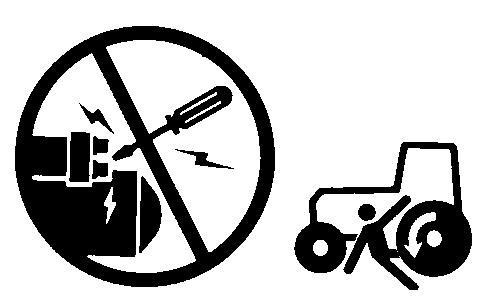
Prevent Machine Runaway
Machinery Runaway
Avoid possible injury or death from machinery runaway.
Do not start engine by shorting across starter terminals. Machine will start in gear if normal circuitry is bypassed.
NEVER start engine while standing on ground. Start engine only from operator s seat, with transmission in neutral or park.
Handle Fluids Safely Avoid Fires
Avoid Fires
When you work around fuel, do not smoke or work near heaters or other re hazards.
Store ammable uids away from re hazards. Do not incinerate or puncture pressurized containers.
Make sure machine is clean of trash, grease, and debris.
Do not store oily rags; they can ignite and burn spontaneously.
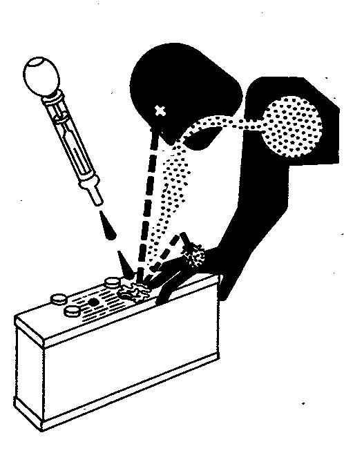
Prevent Battery Explosions
Battery Explosions
Keep sparks, lighted matches, and open ame away from the top of battery. Battery gas can explode.
Never check battery charge by placing a metal object across the posts. Use a volt-meter or hydrometer.
Do not charge a frozen battery; it may explode. Warm battery to 16°C (60°F).
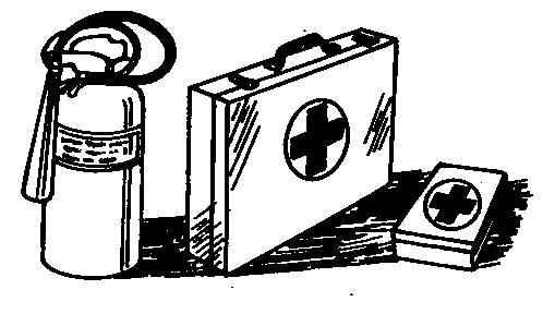
Prepare for Emergencies
First Aid Kit
Be prepared if a re starts.
Keep a rst aid kit and re extinguisher handy.
Keep emergency numbers for doctors, ambulance service, hospital, and re department near your telephone.
Prevent Acid Burns
Sulfuric acid in battery electrolyte is poisonous. It is strong enough to burn skin, eat holes in clothing, and cause blindness if splashed into eyes.
Avoid the hazard by:
Filling batteries in a well-ventilated area.
Wearing eye protection and rubber gloves.
Avoiding breathing fumes when electrolyte is added.
Avoiding spilling or dripping electrolyte.
If you spill acid on yourself:
Apply baking soda or lime to help neutralize the acid.
Flush your eyes with water for 15 30 minutes. Get medical attention immediately.
If acid is swallowed: Do not induce vomiting.
Drink large amounts of water or milk, but do not exceed 2 L (2 quarts).
Acid Burns
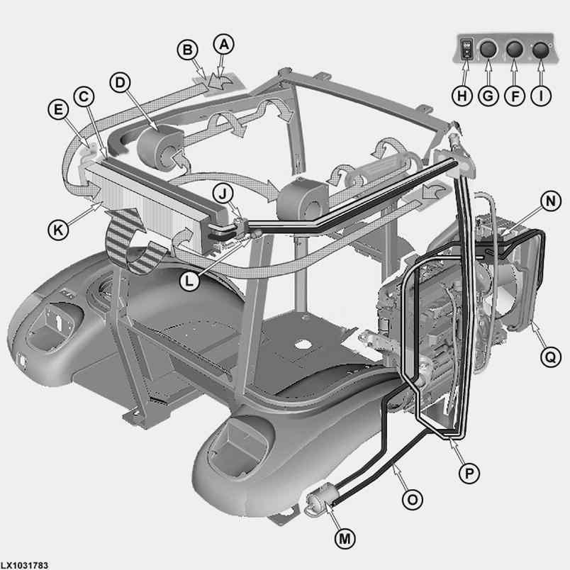
Reference 290-20-020, Refrigerant Circuit Layout
Refrigerant circuit diagram
LEGEND:
A Air inlet (2 used)
B Cab air lter (2 used)
C Radiator
D Fan motor (2 used)
E Heater valve
F Knob for heating
G Knob for cooling
H Compressor switch
I Control knob for fan
J Expansion valve
K Evaporator
L High/low pressure switch
M Receiver-drier N Compressor
O High pressure line
P Low pressure line
Q Condenser, combined with oil cooler
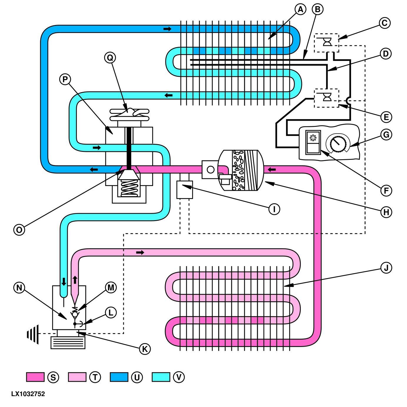
Reference
Components
Circuit
L Presssure relief valve
M Check valve
N Compressor
O Variable throttle
P Expansion valve
Q Thermal head
S Gaseous refrigerant under high pressure
T Liquid refrigerant under high pressure
U Gaseous refrigerant under low pressure
V Liquid refrigerant under low pressure
The air conditioning system operates on the compression principle. The main components are the compressor (N), condenser (J), receiver-drier (H), expansion valve (P), evaporator (A), cooling control knob (G), thermostat switch (E), defrost switch (C), compressor switch (F) and high-low pressure switch (I).
Gaseous refrigerant is compressed in compressor (N), causing it to absorb heat. Then the pressurized gas is fed through the condenser (J), where it transfers its heat to the cooling ns and condenses.
The compressor contains also a relief valve (L) and a check valve (M). The purpose of the relief valve is to release refrigerant under excessive pressure conditions in order to avoid damage to the system.
The check valve prevents the compressor from emptying by enclosing the refrigerant mixture in the compressor when the latter is switched o .
The pressurized liquid refrigerant ows through the receiver-drier (H). There a special lter removes all impurities, moisture and acid.
After it leaves the receiver-drier (H), the refrigerant passes to expansion valve (P), where it is fed through a variable throttle (O). The pressure is still high at the inlet side of the expansion valve. Once the refrigerant has passed through the throttle, however, it is free to expand and cool down.
Expansion is completed in evaporator (A), where the refrigerant returns to its gaseous state and cools down the surrounding area considerably. The refrigerant transfers its cold temperature to the evaporator s cooling ns, and air owing through the evaporator is cooled down.
High/low pressure switch (I) determines the refrigerant pressure in the expansion valve s inlet line. This is required in order to switch o the compressor if the pressure becomes too high or too low.
By means of the compressor switch (F) two operating modes can be selected.
First switch position: Compressor switch at the snow ake symbol means that the air-conditioning system cools down the operator s cab according to the position of temperature control switch, and dries the air.
Second switch position: Compressor switch at circle symbol means that the air-conditioning system is switched o and the compressor is not in operation.
Thermostat switch (E) or defrost switch (C) control the cooling output by switching compressor (N) on or o . The thermostat switch can be reset by turning cooling control knob (G).
The refrigerant ows back via the evaporator return line and is unimpeded as it passes through the housing of expansion valve (P). There it in uences the gas- lled thermal head (Q), which actuates variable throttle (O) in relation to the temperature. In this way, the refrigerant always ows to evaporator (A) at the optimum rate.
Then the gaseous refrigerant is fed back into compressor (N), and the circuit is closed.
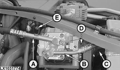
Reference 290-20-031, Functional Description of Components Compressor
Compressor
LEGEND:
A Low pressure line
B High pressure line
C Drive belt pulley
D Magnetic clutch
E Test port
The compressor is located on the engine and is driven by a multi-groove drive belt.
The compressor is of the axial piston type and is controlled by a swashplate.
The purpose of the compressor is to ingest the gaseous refrigerant from the low pressure area, to compress it and send it on to the condenser.
As the low pressure gas volume is compressed the temperature of the refrigerant rises.
The compressor drive assembly includes a magnetic clutch, which allows the compressor to be switched on and o at the compressor switch while the air-conditioning system is in operation.
The compressor housing also serves as the reservoir for refrigerant oil.
Automatic temperature regulation is achieved by switching the thermostat switch on and o . This allows the cooling e ect in the cab to be held constant.
The compressor is switched o and on by the high/low pressure switch if refrigerant pressure is too high or too low.
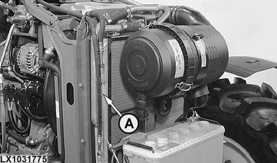
Reference 290-20-032, Functional Description of Components Condenser
Condenser
LEGEND: A Condenser with dust protection
The condenser is located in front of the radiator, looking in the direction of travel. The purpose of the condenser is to cool down the pressurized refrigerant gas so that it condenses and leaves the condenser as a liquid. The same component also houses the hydraulic and transmission oil cooler.
The cooling e ect is produced by the air ow created by the fan. The condenser s inlet is connected to the compressor s pressure connection, its return line to the receiver-drier.
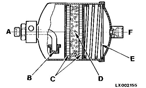
Reference 290-20-033, Functional Description of
Components Receiver-Drier
Receiver-drier operation
LEGEND:
A To expansion valve
B Screen
C Filter elements
D Desiccant (moisture-absorbing material)
E Spring
F From condenser
The receiver-drier performs two functions. Firstly, it receives high pressure refrigerant from the condenser and stores it until it is required by the evaporator. Secondly, it absorbs moisture and acid that would have a detrimental e ect on the system s ability to operate.
Solid foreign bodies are separated out by lter elements (C), whereas the desiccant (D), which lls the space between the lters, absorbs moisture and acid.
The receiver-drier s inlet is connected to the condenser, and its return line to the expansion valve.
The receiver-drier should be replaced every time the air conditioning system is repaired, as the moisture-absorbing material becomes less e ective as time passes.
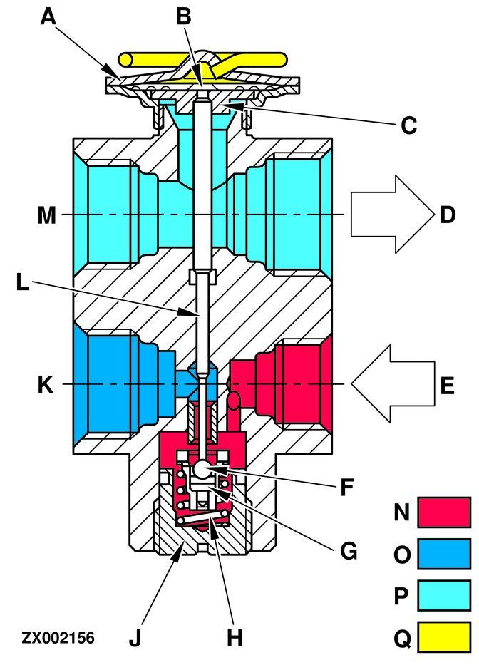
M From evaporator
N Liquid high pressure refrigerant
O Liquid low pressure refrigerant
P Gaseous low pressure refrigerant
Q Gas in thermal head
The expansion valve is located on the right side of the evaporator looking in the direction of forward travel and is connected to the evaporator s inlet and return lines.
The expansion valve is a diaphragm-actuated valve with a stainless steel thermal head. Its purpose is to control the through ow of refrigerant in relation to the return temperature from the evaporator.
If too much refrigerant ows through the evaporator, liquid refrigerant could reach the compressor via the return line, and cause damage to the compressor.
Too much liquid refrigerant is one reason why the system may not be performing well, as the refrigerant does not evaporate completely.
A variable throttle is located in the inlet to the expansion valve. This throttle is formed by valve ball (F) and actuating pin (L). At this point the pressure of the liquid refrigerant is reduced considerably. This allows the refrigerant to expand and change into its gaseous state in the evaporator, thus bringing down the temperature.
Once the refrigerant has left the evaporator, it has to ow through the expansion valve once again. However, it does not do so through the throttle, but through a passage where the refrigerant temperature can be registered by thermal head (A).
The thermal head is lled with gas, which expands and contracts as the temperature rises and falls. This process is employed to produce a movement at diaphragm (B) that is passed on to the throttle. This makes it possible to control the through ow of refrigerant in relation to its temperature.
Reference 290-20-035, Functional Description of Components Thermostat Switch
LEGEND:
A Sensing bulb (gas- lled capillary tube)
B Thermostat switch
C Bowden cable
D Evaporator
Thermostat switch (B) is located in the cab roof.
It is activated by a bowden cable (C) moved by the cooling control switch.
The thermostat switch controls the cooling output of the air conditioning system by switching the compressor on and o , thus regulating the evaporator s temperature. This e ect is determined by the position to which the cooling control switch is set.
The switch consists of a set of contacts which receive current via the fan switch. Current ows on from the thermostat switch to the magnetic clutch for the compressor.
Opening and closing of the electrical contacts is controlled by a gas- lled capillary tube (A) which is tted with a membrane or bellows on one end. The other end of the capillary tube is inserted in the evaporator core (D).
When the thermostat switch is actuated, the switch contacts close, allowing current to ow between the switch and the compressor. However, the compressor comes into operation only if the ventilator fan is also in operation.
Thermostat switch
Once the temperature in evaporator (D) reaches a preselected lower limit, the switch contacts open and the compressor is shut o . The compressor remains inoperative until the evaporator temperature reaches the upper limit value.
When this happens, the switch contacts close again and the compressor comes into operation once more. In this way, the compressor is switched on and o as required and in relation to the temperature inside the evaporator.
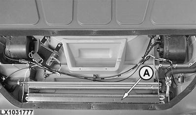
Reference 290-20-036, Functional Description of Components Evaporator
Evaporator
Evaporator (A) is located in the cab roof.
LEGEND: A Evaporator
It allows the heat transfer to take place between the refrigerant and the cab air.
Close beside it is the radiator (heat exchanger) of the heating system which, as required, heats cab air by passing it through the engine coolant. It is controlled via the heating valve.
The refrigerant is still in its liquid form as it comes from the expansion valve. It expands in the evaporator and becomes a gas. The resulting low temperature is transferred to the cooling ns and the air ow produced by the fan transfers its heat to the ns.
The moisture in the ambient air condenses when it comes into contact with the cold evaporator ns. The condensation is drained away via drain hoses.
The gaseous refrigerant is moved from the evaporator outlet via the expansion valve to the compressor.
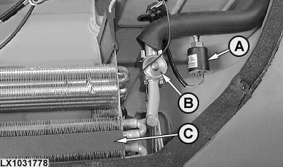
Reference 290-20-037, Functional Description of Components High/Low Pressure Switch
High/low pressure switch
The high/low pressure switch (A) is located in the cab roof directly next to expansion valve (B) and is used to shut o the compressor when the system pressure is too high or low.
The compressor is shut o when system pressure is below 1.5-0.9 bar (150-90 kPa; 22-13 psi) in the low pressure area or over
24.2-27.8 bar (2420-2780 kPa; 355-405 psi) in the high pressure area.
The compressor is turned on when system pressure is over 2.4 bar (240 kPa; 35 psi) in the low pressure area or under 18.8-15.2 bar (1880-1520 kPa; 275-225 psi) in the high pressure area.
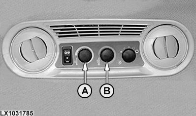
Reference 290-20-038, Functional Description of Components Control Knobs for Heating and Cooling
Control console
LEGEND: A Knob for cooling B Knob for heating
Heating is regulated by heating control knob (B), which is located in the cab roof; cab cooling is regulated at knob (A).
Heating control knob (B) is connected to the heating valve by a bowden cable; it regulates the in ow of warm air.
Cooling control knob (A) is connected to the thermostat switch by a bowden cable; it regulates the in ow of cold air.
Heating and cooling can be regulated independently of one another.
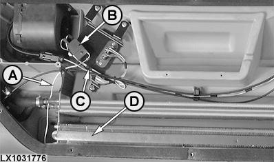
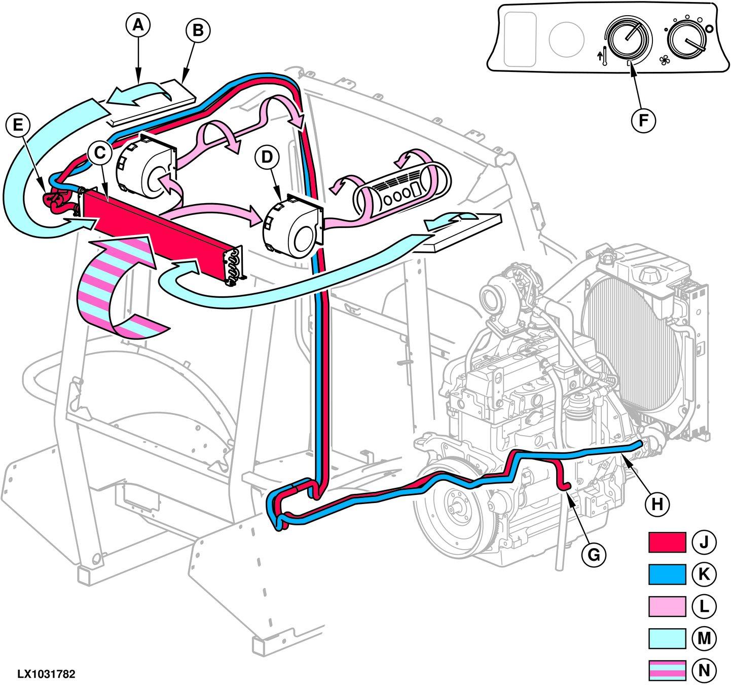
Reference 290-20-040, Heating and Ventilation
block to the heater valve in the roof and from there to the radiator. The heater valve regulates or completely shuts o the ow of coolant. When the valve is open, engine coolant ows through the radiator and via the return line to the coolant pump.
The fan motors suck in fresh air through the air inlets under each side of the cab roof.
The fresh air passes through the air lters into the air ducts in the cab roof and mixes with air recirculated from the cab. This air mixture ows through the radiator and becomes heated. The two fans push warm air through the cab air vents, which can be adjusted to direct the air as desired.
The fans provide a positive pressure in the cab to keep dust and dirt out.
Group 05 - Special Tools (Dealer-Fabricated)
Reference 299-05-001, Special Tools (Dealer-Fabricated) Summary
Reference 299-05-010 , Holding Tool
Reference 299-05-011 , Adjusting Tool
Reference 299-05-015 , Special Tool for 29-BIT CAN BUS DFLX12
Reference 299-05-016 , Solenoid Test Harness DFLX14
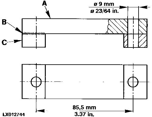
Reference 299-05-010, Holding Tool
Holding tool
LEGEND:
A 30x12x110 mm (1.18x0.472x4.33 in.) at bar steel
B Welded seam
C 30x12x20 mm (1.18x0.472x0.79 in.) at bar steel (2 used)
To hold the shifter shaft detent in place when adjusting shifting mechanism and neutral start switch.
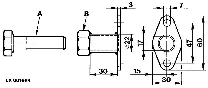
Reference 299-05-011, Adjusting Tool
Adjusting tool
LEGEND:
A M16 x 70 screw
B Attaching ange with M16 nut
Adjusting the 100 Series SCV unit in the dynamic pressure di erence test.
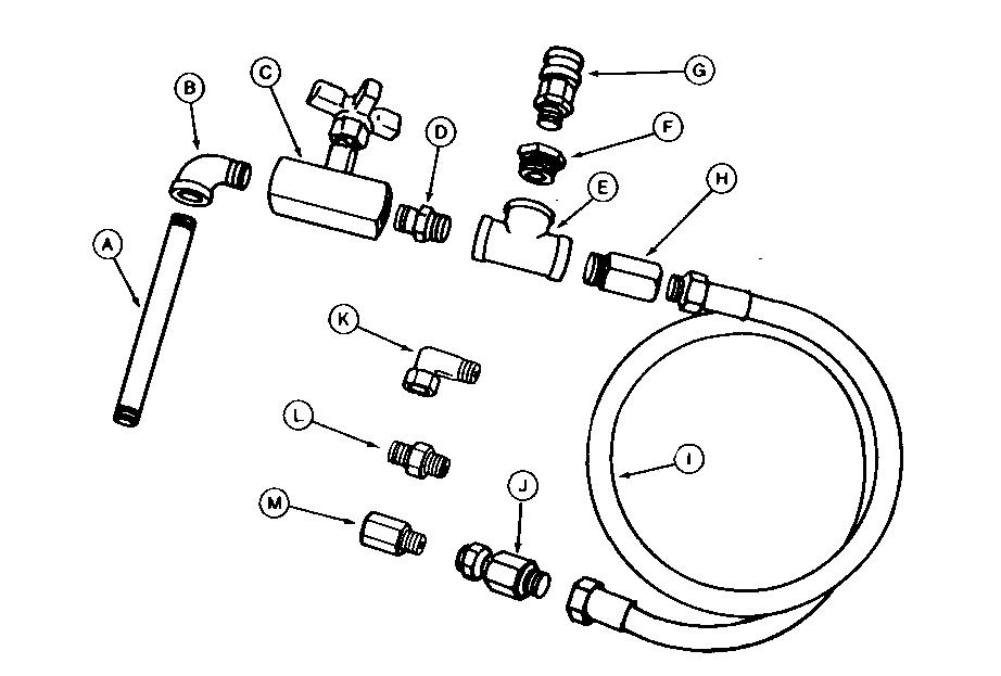
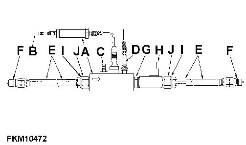
Reference 299-05-012, DFRW2 Needle Valve Test Hose Assembly
DFRW2 needle valve test hose assembly
LEGEND:
A 29H717 3/8 NPT x 15 mm (6 in.) Connecting piece
B 15H199 3/4 NPT Elbow
C JT03402 3/4 NPT Shut-o valve [ Included in tool kit JDH43A ]
D 29H659 (M) 3/8 NPT x 2-1/2 in. connecting piece
E 15H532 3/8 NPT T- tting
F 15H642 3/8 M x 1/4 F NPT Bushing
G JT03265 (M) 1/4 NPT Gauge coupler
H B29217 (F) 3/8 NPT (M) x 3/4-16 (F) O-ring
I AA20991 Hose
J JT03218 3/8 NPT x 9/16-18 (F) JIC Union
K JT03341 9/16-18 JIC SW 90° Elbow
L JT03445 9/16-18 JIC x M14 x 1.5 Connector
M JT03421 9/16-18 JIC x 11/16-16 ORFS Adapter
Use JT03341 (K) for charge pump air leak test.
Use JT03445 (L) for transmission charge pump air leak test.
Use JT03421 (M) to ow test axle lube pump.
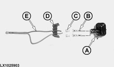
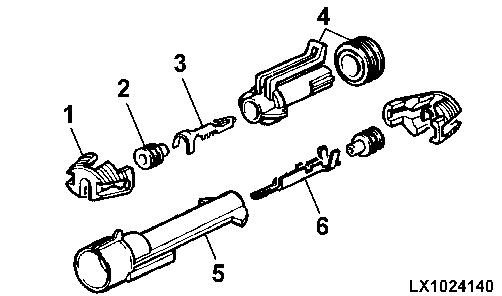
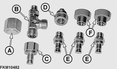
Reference 299-05-015, Special Tool for 29-BIT CAN BUS DFLX12
Special tool for 29-BIT- CAN BUS continuity test (terminators A61 and A62)
LEGEND:
A 57M7263 pin contact connector body (2 used)
B 57M7252 pin (4 used)
C 57M7377 dust cover (4 used)
D 57M7291 connector (2 used)
E [ AL153274 resistor Between pins E and F ] (120 ohm) (2 used)
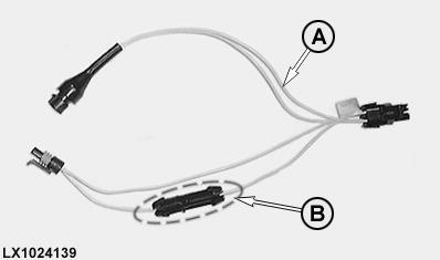
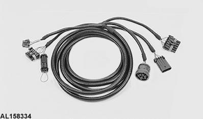
Reference 299-05-016, DFLX14 Solenoid Test Harness
Solenoid test harness
LEGEND:
A JDG774 test harness
B Additional connector for checking current strength
NOTE:
Order solenoid test harness JDG774 through normal parts channels.
The additional connector must be installed between the solenoid plug (cable to pin A) and the measuring plug.
The additional connector can be used to check current strength at the solenoids as well as voltages.
Group 10 - Special Tools and Test Equipment
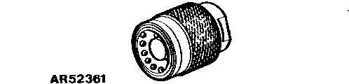
AR52361 - Socket
AR52361 - Socket
AR52361 - Socket
[ Available as spare part ]
Checking the trailer brake valve.
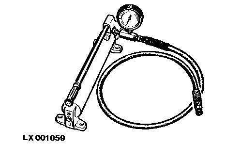
D01019AA - Manually operated hydraulic pump
D01019AA - Manually operated hydraulic pump
D01019AA - Manually operated hydraulic pump
Testing and adjusting shock valves of steering valve.
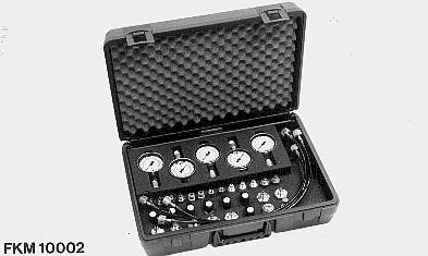
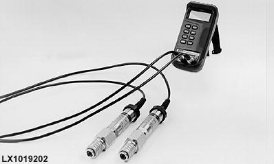
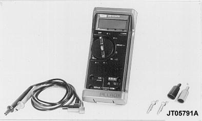
FKM10002 or JT05470 - Pressure test kit
FKM10002 or JT05470
Pressure test kit for hydraulic checks
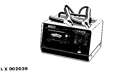
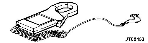
Battery Load Tester FKM10409
FKM10409 - Battery load tester
FKM10409 - Battery load tester
Checking the battery.
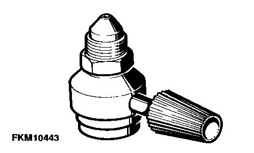
FKM10443 - Charging valve
FKM10443 - Charging valve
FKM10443 - Charging valve
Filling the system.
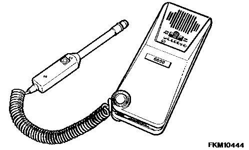
FKM10444 - Leak detector
FKM10444 - Leak detector
FKM10444 - Leak detector
Identifying refrigerant leaks.
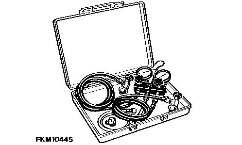
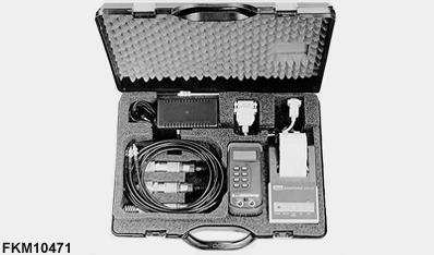
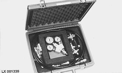
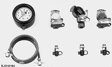
FKM10445 - Universal pressure test kit
FKM10445 - Universal pressure test kit
FKM10445 - Universal pressure test kit
Evacuating, lling and checking the air-conditioning system.