tm1926 - 330CLC and 370C Excavator
Technical Manual
Main Sections
Foreword
Technical Information Feedback Form
General Information
Safety
Operational Checkout Procedure
Operational Checkout Procedure
Engine
Theory of Operation
Diagnostic Information
Tests
Electrical System
System Information
System Diagrams
Sub-System Diagnostics
References
Power Train
Theory of Operation
Diagnostic Information
Hydraulic System
Theory Of Operation
Diagnostic Information
Heating and Air Conditioning
Theory Of Operation
Diagnostic Information
Tests
Dealer Fabricated Tools
Dealer Fabricated Tools
Information
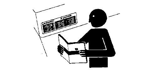
Follow Safety Instructions
Operate Only If Qualified
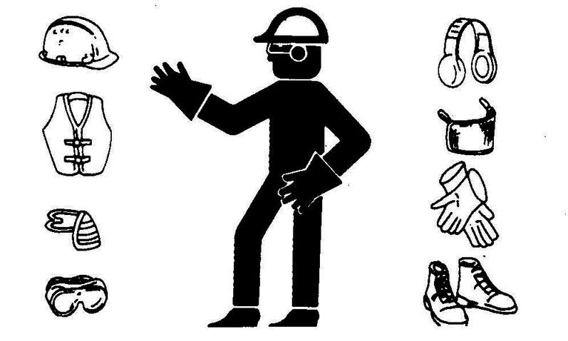
Wear Protective Equipment
Avoid Unauthorized Machine
Modifications Add Cab Guarding for
Special Uses
Inspect Machine
Stay Clear of Moving Parts
Avoid High-Pressure Oils
Beware of Exhaust Fumes
Prevent Fires
Prevent Battery Explosions
Handle Chemical Products Safely
Dispose of Waste Properly
Prepare for Emergencies
Use Steps and Handholds Correctly
Start Only From Operator's Seat
Use and Maintain Seat Belt
Prevent Unintended Machine Movement
Avoid Work Site Hazards
Keep Riders Off Machine
Avoid Backover Accidents
Avoid Machine Tip Over
Use Special Care When Lifting Objects
Add and Operate Attachments Safely
Park and Prepare for Service Safely
Service Cooling System Safely
Remove Paint Before Welding or Heating
Make Welding Repairs Safely
Drive Metal Pins Safely
Engine Speed Control System Operation
Diagnose Engine Malfunctions
Engine Speed Test
Fuel Line Leakage Test
Air Filter Restriction Indicator Switch Test
Air Intake System Leakage Test
Radiator Air Flow Test
Engine Power Test Using Turbocharger Boost Pressure
Electrical Diagram Information
Explanation of Wire Markings
Fuse Specifications
System Functional Schematic and Master Legend
Overall Machine Harnesses Component Location Diagram
Cab Harness (W1) and Alternator Relay Sub-Harness (W11) Component Location Diagram
Cab Harness (W1) and Alternator Relay Sub-Harness (W11) Component Location Diagram Harness Connectors
Engine Harness (W2) Component Location Diagram
Engine Harness (W2) Component Location Diagram Harness Connectors
Monitor Harness (W3) and Windshield Wiper Motor Sub-Harness (W6) Component Location Diagram
Monitor Harness (W3) and Windshield Wiper Motor Sub-Harness (W6) Component Location Diagram Harness Connectors
Air Conditioner and Heater Harness (W7) Component Location
Air Conditioner and Heater Harness (W7) Wiring Diagram
Pump Harness (W12) Component Location Diagram
Pump Harness (W12) Component Location Diagram Harness Connectors
Engine Control Unit Harness (W19) Component Location Diagram
Engine Control Unit Harness (W19) Component Location Diagram Harness Connectors
Engine Control Unit Engine Harness (W20) Component Location Diagram
Engine Control Unit Engine Harness (W20) Component Location Harness Connectors
Fuel Injector Harness (W22) Component Location Diagram
Fuel Injector Harness (W22) Component Location Diagram Harness Connectors Starting
Diagnostic Display Unit (DDU) Operation
Engine Service Codes
Laptop Computer Connection To Engine Control Unit Using Service ADVISOR
Laptop Computer Connection To Pump and Valve Controller Using Service ADVISOR or Excavator Diagnostic Program
Excavator Diagnostic Program General Description and Overview
Reading Service Codes Without Laptop Computer
Monitor Display Diagnostic System Operation
Monitor Data Items
Pump and Valve Controller Service Codes
Alternator Test Procedure
Fuse Test
Pump and Valve Controller Pressure Sensors Test
Pump and Valve Controller Solenoids Test
Pump and Valve Controller Temperature Sensor Test
Engine Control Unit Pressure Sensors and Solenoids Test
Engine Control Unit Temperature Sensors Test
Engine Control Unit Speed Sensors Test
Engine Speed (N) Sensor Test
Electrical Component Checks
Remove and Install Batteries
Remove and Install Propel Alarm Cancel Switch
Remove and Install Key Switch
Remove and Install Travel Alarm
Remove and Install Windshield Wiper Enable Switch
Remove and Install Rear Cover
Remove and Install Switch Panel (A4)
Remove and Install Monitor Controller and Display (A5)
Disconnect Tab Retainer Connectors
Disconnecting Spring Wire Clip Connectors
Replace DEUTSCH DEUTSCH is a trademark of the Deutsch Co Connectors
Install DEUTSCH DEUTSCH is a trademark of the Deutsch Co Contacts
Replace WEATHER PACK WEATHER PACK is a trademark of Packard Electric Connector
Install WEATHER PACK WEATHER PACK is a trademark of Packard Electric Contacts
Remove Connector Body from Blade Terminals
Section 9020: Power Train
Group 05: Theory of Operation
Track Adjuster And Recoil Spring Operation
Propel Gearbox Operation 330CLC (S N 082518)
Propel Gearbox Operation 330CLC (S N 082519 )
Propel Gearbox Operation 370C
Group 15: Diagnostic Information
Diagnose Undercarriage Components Malfunctions
Measure Swing Bearing Wear
Section 9025: Hydraulic System
Group 05: Theory Of Operation
Hydraulic System Diagram and Operation
Pilot System Diagram and Operation
Pilot Pump, Pressure Regulating Valve, and Filter Operation
Pilot Shut-Off Valve Operation
Pilot Controller Operation
Propel Pilot Controller Operation
Flow Regulator Valve and Warm-Up Circuit Operation
Hydraulic Pumps and Drive Gearbox Operation
Hydraulic Pump Regulator Operation
Engine Speed Sensing Control Circuit Operation
Control Valve Operation
Control Valve Check Valves Identification and Operation
System Relief and Power Boost Valve Circuit Operation
Circuit Relief and Anticavitation Valve Operation
Pump Control Valve Operation
Propel Flow Combiner Valve Circuit Operation
Arm Regenerative Valve Circuit Operation
Boom Regenerative Valve Operation
Bucket Regenerative Valve Circuit Operation
Arm Rod End and Boom Reduced Leakage Valves Operation
Arm Head End Reduced Leakage Valve Operation
Boom Manual Lower Needle Valve Operation
Bucket Flow Rate Valve Operation
Propel Flow Rate Valve Operation
Bypass Shut-Off Valve Operation
Swing Gearbox Operation
Swing Motor, Crossover Relief Valve and Make-up Valve Operation
Swing Motor Park Brake Release Valve Operation
Rotary Manifold Operation
Propel Motor and Park Brake Valve Operation 330CLC (S N 082518)
Propel Motor and Park Brake Valve Operation 330CLC (S N 082519 )
Propel Speed Control Circuit Operation 330CLC
Propel Motor and Park Brake Valve Operation 370C
Propel Speed Control Circuit Operation 370C
Cylinder Operation
Hydraulic System Circuit Symbols
Hydraulic System Schematic
Group 15: Diagnostic Information
Diagnostic Procedure
Diagnose Electronic and Control Valve Component Malfunctions
Diagnose Hydraulic System Malfunctions
Diagnose Pilot Circuit Malfunctions
Diagnose Dig Circuit Malfunctions
Diagnose Swing Circuit Malfunctions
Diagnose Propel System Malfunctions
Control Valve Line Identification
Main Hydraulic System Component Location
Pilot Controllers-to-Flow Regulator Valve Component Location Excavator Pattern
Pilot Controllers-to-Flow Regulator Valve Component Location Backhoe Pattern
Pilot Flow Regulator Valve-to-Control Valve Component Location
Propel Hydraulic System Component Location
JT05801 Clamp-On Electronic Tachometer Installation
JT05800 Digital Thermometer Installation
JT02156A Digital Pressure/Temperature Analyzer Installation
Hydraulic Oil Filter Inspection Procedure
Hydraulic Oil Cleanup Procedure Using Portable Filter Caddy
Hydraulic System Warm-Up Procedure
Cylinder Drift Test Boom Arm and Bucket
Pilot Pressure Regulating Valve Test and Adjustment
Control Valve Spool Pilot Actuation Pressure Test
System Relief and Power Boost Valve Test and Adjustment
Arm Reduced Leakage Relief Valve Test And Adjustment
Circuit Relief Valve Test and Adjustment
Swing Motor Crossover Relief Valve Test and Adjustment
Propel Motor Crossover Relief Valve Test and Adjustment 330CLC (S N 082518)
Propel Motor Crossover Relief Valve Test and Adjustment 330CLC (S N 082519 )
Propel Motor Crossover Relief Valve Test and Adjustment 370C
Power Boost Propel Speed and Arm Regenerative Solenoid Valve Test and Adjustment
Pump Control Valve Test
Hydraulic Pump Regulator Test and Adjustment Minimum Flow 330CLC
Hydraulic Pump Regulator Test and Adjustment Minimum Flow 370C
Hydraulic Pump Regulator Test and Adjustment Maximum Flow 330CLC
Hydraulic Pump Regulator Test and Adjustment Maximum Flow 370C
Hydraulic Pump Regulator Test and Adjustment Engine Pulldown
Hydraulic Pump Flow Test
Swing Motor Leakage Test
Propel Motor Leakage Test 330CLC (S N 082518)
Propel Motor Leakage Test 330CLC (S N 082519 )
Propel Motor Leakage Test 370C
Air Conditioning System Cycle Of Operation
Diagnose Air Conditioning System Malfunctions
Diagnose Heater System Malfunctions
Air Conditioner and Heater Diagnostic System Operation
Air Temperature Is Uncontrollable
Vent Control System Is Inoperable
Fresh Air or Recirculated Air Control System is Inoperable
Air Volume is Uncontrollable
Air Conditioner Controller Diagnostic Trouble Codes
21 - Mix Door Open Circuit
-21 - Mix Door Short Circuit
22 - Mode Encoder Open Circuit
23 - In-Cab Ambient Temperature Sensor Open Circuit
-23 - In-Cab Ambient Temperature Sensor Short Circuit
24 - Outdoor Ambient Temperature Sensor Open Circuit
-24 - Outdoor Ambient Temperature Sensor Short Circuit
25 - Coolant Temperature Sensor Open Circuit
-25 - Coolant Temperature Sensor Short Circuit
26 - Solar Radiation Sensor Open Circuit
-26 - Solar Radiation Sensor Short Circuit
Heating and Air Conditioner Component Location
Heating and Air Conditioning System Checks
R134a Air Conditioning System Test
Air Conditioning Compressor Clutch Test
Refrigerant Leak Test
Refrigerant Hoses and Tubing Inspection
Air Conditioner and Heater Sensors Test
Table of Contents
Avoid High-Pressure Oils
Beware of Exhaust Fumes
Prevent Fires
Prevent Battery Explosions
Handle Chemical Products Safely
Dispose of Waste Properly
Prepare for Emergencies
Use Steps and Handholds Correctly
Start Only From Operator's Seat
Use and Maintain Seat Belt
Prevent Unintended Machine Movement
Avoid Work Site Hazards
Keep Riders Off Machine
Avoid Backover Accidents
Avoid Machine Tip Over
Use Special Care When Lifting Objects
Add and Operate Attachments Safely
Park and Prepare for Service Safely
Service Cooling System Safely
Remove Paint Before Welding or Heating
Make Welding Repairs Safely
Drive Metal Pins Safely
Operational Checkout
Operational Checkout
Operational Checkout
Engine Speed Control System Operation
Engine RPM Dial
Hydraulic Oil Warm-up
Engine Speed Control System Operation
Engine RPM Dial
Hydraulic Oil Warm-up
Engine Speed Control System Operation
Engine RPM Dial
Hydraulic Oil Warm-up
Diagnose Engine Malfunctions
Diagnose Engine Malfunctions
Engine Speed Test
Engine Speed Test
Fuel Line Leakage Test
Air
Air
Radiator
Electrical Diagram Information
System Functional Schematic Diagram
Wiring Diagram If Provided
Component Location Diagram
Connector End View Diagram If Provided
Electrical Schematic Symbols
Explanation of Wire Markings247
Explanation of Wire Markings248
Fuse Specifications249
System Functional Schematic and Master Legend251
Overall Machine Harnesses Component Location Diagram259
Cab Harness (W1) and Alternator Relay Sub-Harness (W11) Component Location Diagram261
Cab Harness (W1) and Alternator Relay Sub-Harness (W11) Component Location Diagram
Harness Connectors265
Engine Harness (W2) Component Location Diagram267
Engine Harness (W2) Component Location Diagram Harness Connectors269
Monitor Harness (W3) and Windshield Wiper Motor Sub-Harness (W6) Component Location
Diagram 271
Monitor Harness (W3) and Windshield Wiper Motor Sub-Harness (W6) Component Location
Diagram Harness Connectors274
Air Conditioner and Heater Harness (W7) Component Location276
Air Conditioner and Heater Harness (W7) Wiring Diagram278
Pump Harness (W12) Component Location Diagram279
Pump Harness (W12) Component Location Diagram Harness Connectors281
Engine Control Unit Harness (W19) Component Location Diagram282
Engine Control Unit Harness (W19) Component Location Diagram—Harness Connectors284
Engine Control Unit Engine Harness (W20) Component Location Diagram286
Engine Control Unit Engine Harness (W20) Component Location Harness Connectors288
Fuel Injector Harness (W22) Component Location Diagram289
Fuel Injector Harness (W22) Component Location Diagram Harness Connectors290
Starting and Charging Circuit Theory of Operation291
Starting and Charging Circuit Theory of Operation293
Travel Alarm Circuit Theory of Operation295
Monitor Controller and Display Circuit Theory of Operation297
HOUR METER AND GAUGES
STATUS INDICATORS
Air Filter Restriction Indicator Light (H33)
Fuel Level Indicator Light (H13)
Engine Coolant Temperature Indicator Light (H32) Engine Coolant Temperature Gauge Sender (B9) Engine Oil Pressure Indicator Light (H17)
Engine Coolant Level Indicator Light (H11)
Engine Oil Level Indicator Light (H19)
Alternator Voltage Indicator Light (H18)
Monitor Controller and Display Alarm (H8)
Check Engine Indicator Light (H10)
CONTROL SWITCHES AND INDICATORS
Windshield Wiper and Washer Switch (S9)
Work Light Switch (S6)
Propel Speed Switch (S8) Auto-Idle/Auto-
Acceleration Switch (S13)
(S12)
Engine Control Unit Circuit Theory of Operation
High Pressure Fuel Pump (Solenoid 1) (Y7) and High
Electronic Fuel Injectors (Y11 Y16)
Pump and Valve Controller Circuit Theory of Operation
Pump and Valve Controller (A7)
Pump and Valve Controller Sensors
Pump and Valve Controller Solenoids
Fuel Pump (Solenoid 2) (Y8)
Windshield Wiper And Washer Circuit Theory of Operation
Air Conditioner and Heater Controller Circuit Theory of Operation
Diagnostic Display Unit (DDU) Operation
Accessing Menu
Viewing Active Service Codes
Access Stored Codes
Clearing Active Or Stored Service Codes From Diagnostic Display Unit Memory
Diagnostic Display Unit (DDU) Operation
Accessing Menu
Viewing Active Service Codes
Access Stored Codes
Clearing Active Or Stored Service Codes From Diagnostic Display Unit Memory
Engine Service Codes
Laptop Computer Connection To Engine Control Unit Using Service ADVISOR
Laptop Computer Connection To Pump and Valve Controller Using Service ADVISOR or
Excavator Diagnostic Program
Excavator Diagnostic Program General Description and Overview
Troubleshooting Reading
12 V
24 V
Pump and Valve Controller Pressure Sensors Test
Pump and Valve Controller Solenoids Test
Pump and Valve Controller Temperature Sensor Test
Engine Control Unit Pressure Sensors and Solenoids Test
Engine Control Unit Temperature Sensors Test
Engine Control Unit Speed Sensors Test
Engine Speed (N) Sensor Test
Electrical Component Checks
Remove and Install Batteries
Table of Contents
Remove and Install Rear Cover
Remove and Install Switch Panel (A4)
Remove and Install Monitor Controller and Display (A5)
Disconnect Tab Retainer Connectors
Disconnecting Spring Wire Clip Connectors
Replace DEUTSCH ™ Connectors
Install DEUTSCH ™ Contacts
Replace WEATHER PACK ™ Connector
Install WEATHER PACK ™ Contacts
Remove Connector Body from Blade Terminals
Track Adjuster And Recoil Spring Operation
Track Adjuster And Recoil Spring Operation
Track Adjuster And Recoil Spring Operation
Propel Gearbox Operation 330CLC (S.N. 082518)
Propel Gearbox Operation 330CLC (S.N. 082519 )
Propel Gearbox Operation 370C
Diagnose Undercarriage Components Malfunctions
Diagnose Undercarriage Components Malfunctions
Measure
Hydraulic System
Hydraulic
Hydraulic
Hydraulic
Hydraulic System Diagram and Operation
Hydraulic Oil Return Filter
Pilot System Diagram and Operation
Pilot Pump, Pressure Regulating Valve, and Filter Operation
Pilot Shut-Off Valve Operation
Pilot Controller Operation
Propel Pilot Controller Operation
Flow Regulator Valve and Warm-Up Circuit Operation
Flow Regulator Valve
Warm-Up
Hydraulic Pump Regulator Component Identification
Hydraulic Pump Regulator Control by Pump 1 (Front) and Pump 2 (Rear) Control Valve
Decreasing Flow Rate (Displacement)
Hydraulic Pump Regulator Control By Supply Oil Pressure
Hydraulic Pump Regulator Control By Speed Sensing Pilot Oil
Engine Speed Sensing Control Circuit Operation
Control Valve Operation
Control Valve Check Valves Identification and Operation
System Relief and Power Boost Valve Circuit Operation
Boost and Auto-Power Lift Control Circuit Operation Power Boost Solenoid Valve (SG)
Circuit Relief and Anticavitation Valve Operation
Pump Control Valve Operation
Propel Flow Combiner Valve Circuit Operation
Table of Contents
Arm Regenerative Valve Circuit Operation
Arm Regenerative Solenoid Valve (SC)
Boom Regenerative Valve Operation
Bucket Regenerative Valve Circuit Operation
Arm Rod End and Boom Reduced Leakage Valves Operation
Arm Head End Reduced Leakage Valve Operation
Boom Manual Lower Needle Valve Operation
Bucket Flow Rate Valve Operation
Propel Flow Rate Valve Operation
Bypass Shut-Off Valve Operation
Swing Gearbox Operation
Swing Motor, Crossover Relief Valve and Make-up Valve Operation
Swing Motor Park Brake Release Valve Operation
Rotary Manifold Operation
Propel Motor and Park Brake Valve Operation 330CLC (S.N. 082518)
Propel Motor and Park Brake Valve
Propel Motor Slow and Fast Speed
Propel Motor Park Brake Release Circuit
Propel Motor Counterbalance Valve
Propel Motor and Park Brake Valve Operation 330CLC (S.N. 082519 )
Propel Motor Slow Speed Operation
Propel Motor Fast Speed Operation
Propel Speed Solenoid Valve (SI)
Propel Motor and Park Brake Valve Operation 370C
Propel Motor and Park Brake Valve Housing
Propel Motor and Park Brake Valve Components
Propel Motor Slow Speed Operation
Propel Motor Fast Speed Operation
Counterbalance Valve
Propel Motor Crossover Relief Valves
Propel Motor Park Brake
Propel Speed Control Circuit Operation 370C
Propel Speed Control Circuit Operation—330CLC Cylinder Operation
Pilot Controllers-to-Flow Regulator Valve Component Location Excavator Pattern
Pilot Controllers-to-Flow Regulator Valve Component Location Backhoe Pattern
JT05801 Clamp-On Electronic Tachometer Installation
JT05801 Clamp-On Electronic Tachometer Installation
JT05800 Digital Thermometer Installation
JT02156A Digital Pressure/Temperature Analyzer Installation
Hydraulic Oil Filter Inspection Procedure
Hydraulic Oil Cleanup Procedure Using Portable Filter Caddy
Hydraulic System Warm-Up Procedure
Cylinder Drift Test Boom, Arm and Bucket
Pilot Pressure Regulating Valve Test and Adjustment
Control Valve Spool Pilot Actuation Pressure Test
System Relief and Power Boost Valve Test and Adjustment
Arm Reduced Leakage Relief Valve Test And Adjustment
Circuit Relief Valve Test and Adjustment
Swing Motor Crossover Relief Valve Test and Adjustment
Propel Motor Crossover Relief Valve Test and Adjustment 330CLC (S.N. 082518)
Propel Motor Crossover Relief Valve Test and Adjustment 330CLC (S.N. 082519 )
Propel Motor Crossover Relief Valve Test and Adjustment 370C
Power Boost, Propel Speed, and Arm Regenerative Solenoid Valve Test and Adjustment
Pump Control Valve Test
Hydraulic Pump Regulator Test and Adjustment—Minimum Flow—330CLC
Hydraulic Pump Regulator Test and Adjustment Minimum Flow 370C
Hydraulic Pump Regulator Test and Adjustment Maximum Flow 330CLC
Hydraulic Pump Regulator Test and Adjustment Maximum Flow 370C
Hydraulic Pump Regulator Test and Adjustment Engine Pulldown
Hydraulic Pump Flow Test
Swing Motor Leakage Test
Propel Motor Leakage Test—330CLC (S N —082518)
Propel Motor Leakage Test 330CLC (S N 082519 )
Propel Motor Leakage Test 370C
Air Conditioning System Cycle Of Operation
Air Conditioning System Cycle Of Operation
Air Conditioning System Cycle Of Operation
Diagnose Air Conditioning System Malfunctions
Diagnose Air Conditioning System Malfunctions
Diagnose
Air Conditioner Controller Diagnostic Trouble Codes
Heating and Air Conditioner Component Location
Heating and Air Conditioning System Checks Table of
R134a Air Conditioning System Test
Air Conditioning Compressor Clutch Test
Refrigerant Leak Test
Refrigerant Hoses and Tubing
Inspection Air Conditioner and Heater
Sensors Test DFT1218 Split Flange
Hose Cap DFT1218 Split Flange Hose Cap DFT1218