Introduction
Foreword
Thismanualiswrittenforanexperiencedtechnician. Essentialtoolsrequiredinperformingcertainservice workareidentifiedinthismanualandare recommendedforuse.
Livewithsafety:Readthesafetymessagesinthe introductionofthismanualandthecautionspresented throughoutthetextofthemanual.
Thisisthesafety-alertsymbol.Whenyouseethis symbolonthemachineorinthismanual,bealertto thepotentialforpersonalinjury.
Technicalmanualsaredividedintwoparts:repairand operationandtests.Repairsectionstellhowtorepair thecomponents.Operationandtestssectionshelpyou identifythemajorityofroutinefailuresquickly.
Informationisorganizedingroupsforthevarious componentsrequiringserviceinstruction.Atthe beginningofeachgrouparesummarylistingsofall applicableessentialtools,serviceequipmentandtools, othermaterialsneededtodothejob,servicepartskits, specifications,weartolerances,andtorquevalues.
TechnicalManualsareconciseguidesforspecific machines.Theyareon-the-jobguidescontainingonly thevitalinformationneededfordiagnosis,analysis, testing,andrepair.
Fundamentalserviceinformationisavailablefrom othersourcescoveringbasictheoryofoperation, fundamentalsoftroubleshooting,generalmaintenance, andbasictypeoffailuresandtheircauses.
DX,TMIFC–19–29SEP98–1/1
SECTION10—General Group16—HydraulicValveStack(S.N.—715300) Group17—HydraulicValveStack(S.N.715301—)
Group05—Safety Group10—SpecificationsGroup20—HydraulicCylinders Group25—Motors Group15—Tune-UpandAdjustment Group20—FuelsandLubricantsGroup30—Accumulator
SECTION20—Engine
SECTION80—SeparatorShell Group05—RemoveandInstallEngine Group05—GullWingDoors Group10—CoolingSystem Group15—LowerEngineRepair
SECTION90—OperatorStationRepair Group05—AirConditioningSystem(R134a)
SECTION30—FuelandAirRepair Group10—SystemComponents Group05—AirIntakeSystem Group15—Cab Group10—DieselFuelSystem
SECTION40—ElectricalSystem
SECTION110—FeederHouseRepair
Group05—Conveyor Group05—Batteries Group10—TopShaftandSlipClutch Group10—HarnessandConnectorRepair Group15—FeederHouseDrivesandReverser Group15—WireHarnessRouting GearCase Group20—Fuses,CircuitBreakersandRelays Group20—CONTOURMASTERTiltCylinder Group25—Lighting Group25—CONTOURMASTERTiltFrame Group30—OperatorsStation Group35—SensorsandSwitches
SECTION120—Separator Group40—Wiper Group05—SeparatorRepair Group45—Alternator Group10—SeparatorDrives Group50—StartingMotor Group15—ResidueDisposal Group55—ElectricalEngineControl
Group20—ConveyorAugers,CleaningFanAnd Group60—GREENSTARComponents ChafferAndSieveFrame Group25—TailingsElevatorandAugers
SECTION50—PowerTrainRepair Group30—PrimaryCountershaftGearCase
Group05—TransmissionandDifferential Group35—HeaderElectromagneticClutch Group10—SingleReductionFinalDrive—Heavy Duty
Group15—HydrostaticSystem
SECTION130—GrainTankandUnloadingSystem Group20—CamLobeMotor Repair Group25—TiresandWheels Group05—GrainTankCrossAugers Group10—UnloadingAugerSystemDrives
SECTION60—PowerSteeringandBrakes
Group15—VerticalUnloadingAugerandLower Group05—Steering GearCase Group10—Brakes Group20—HorizontalUnloadingAugerandGear Case Group25—CleanGrainElevator
SECTION70—HydraulicRepair Group05—HydraulicReservoirGroup30—GrainTankandExtensions Group10—HydraulicPumps Group15—HydraulicValves
Allinformation,illustrationsandspecificationsinthismanualarebasedon thelatestinformationavailableatthetimeofpublication.Therightis reservedtomakechangesatanytimewithoutnotice.
Group05—Safety 10-05-1
SAEFourBoltFlangeCapScrewTorque Values—HighPressureApplications ...... 10-10-36 ExternalHexagonPortPlugTorqueChart...10-10-37
Group10—Specifications PreventHydraulicSystemContamination 10-10-38
GroundSpeeds(FastIdle)TwoSpeedFour CheckOilLinesandFittings 10-10-39 WheelDrive 10-10-1
BasicElectricalComponentHandling/ TurningRadius ......................... 10-10-2 PrecautionsForVehiclesEquippedWith
Specifications—9560STSCombine 10-10-5
OperatingSpeeds—9560STS ............. 10-10-3 ComputerControlledSystems 10-10-40
Dimensions—9560STSCombine 10-10-7
Group15—Tune-UpandAdjustment
DimensionReferencePoints—9560STS Tune-UpandAdjustment 10-15-1 Combine 10-10-8 CareandMaintenanceofBelts 10-15-2
OperatingSpeeds—9660STS,9760STS DefectiveBelts 10-15-4 Combines 10-10-9
Specifications—9660STSCombine 10-10-11
Specifications—9760STSCombine 10-10-13
Dimensions—9660STS,9760STS
Group20—FuelsandLubricants HandleFuelSafely—AvoidFires ............ 10-20-1
DimensionReferencePoints—9660STS, 9760STSCombines 10-10-17Bio-DieselFuel
OperatingSpeeds—9860STSCombine 10-10-18
Specifications—9860STSCombine(S.N.—TestingDieselFuel
715700) 10-10-20
Specifications—9860STSCombine(S.N.OperatinginWarmTemperatureClimates
SupplementalCoolantAdditives 10-20-7 715701—) 10-10-22
Dimensions—9860STSCombine 10-10-24AdditionalInformationAboutDiesel EngineCoolantsandSupplementalCoolant DimensionReferencePoints—9860STS Combine ........................... 10-10-25Additives
MetricBoltandScrewTorqueValues ....... 10-10-26
UnifiedInchBoltandScrewTorqueDieselEngineBreak-InOil 10-20-10 DieselEngineOil 10-20-11 Values 10-10-27
SealantsandAdhesivesCross-ReferenceExtendedDieselEngineOilService Intervals 10-20-12 Chart 10-10-28
FaceSealFittingsAssemblyandOILSCANandCOOLSCAN 10-20-12 HydrostaticDriveSystem,MainHydraulic Installation—AllPressureApplications 10-10-29
MetricFaceSealFittingTorqueSystemandMainEngineGearCase Oils ............................... 10-20-13 Chart—StandardPressureApplications .... 10-10-30
MetricFaceSealFittingTorqueChart—HighTransmission,FinalDrives,FeederHouse Reverser,LoadingAuger,Primary PressureApplications ................. 10-10-31
SAEFaceSealFittingTorqueCountershaftandTwo-SpeedSeparator DriveGearCases 10-20-14 Chart—StandardPressureApplications 10-10-32
SAEFaceSealFittingTorqueChart—HighGrease 10-20-15 BrakeFluid 10-20-15 PressureApplications 10-10-33
FourBoltFlangeFittingsAssemblyandLubricantStorage 10-20-16 AlternativeandSyntheticLubricants 10-20-16 Installation—AllPressureApplications 10-10-34
SAEFourBoltFlangeCapScrewTorque Continuedonnextpage Values—StandardPressureApplications...10-10-35
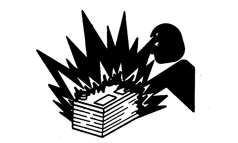
PreventBatteryExplosions
Keepsparks,lightedmatches,andopenflameawayfrom thetopofbattery.Batterygascanexplode.
Nevercheckbatterychargebyplacingametalobject acrosstheposts.Useavolt-meterorhydrometer.
Donotchargeafrozenbattery;itmayexplode.Warm batteryto16°C(60°F).
AvoidHeatingNearPressurizedFluidLines
Flammablespraycanbegeneratedbyheatingnear pressurizedfluidlines,resultinginsevereburnsto yourselfandbystanders.Donotheatbywelding, soldering,orusingatorchnearpressurizedfluidlinesor otherflammablematerials.Pressurizedlinescan accidentallyburstwhenheatgoesbeyondtheimmediate flamearea.
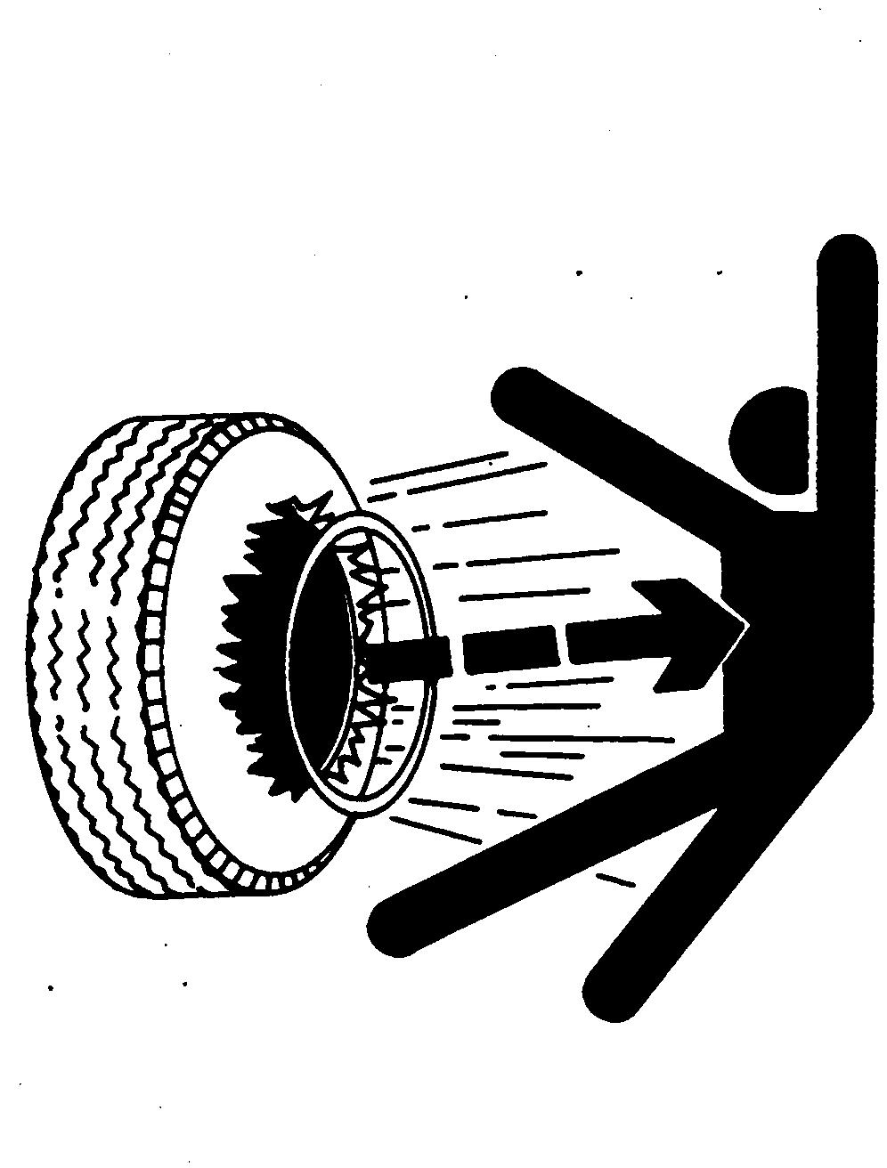
ServiceTiresSafely
Explosiveseparationofatireandrimpartscancause seriousinjuryordeath.
Donotattempttomountatireunlessyouhavetheproper equipmentandexperiencetoperformthejob.
Alwaysmaintainthecorrecttirepressure.Donotinflate thetiresabovetherecommendedpressure.Neverweldor heatawheelandtireassembly.Theheatcancausean increaseinairpressureresultinginatireexplosion. Weldingcanstructurallyweakenordeformthewheel.
Wheninflatingtires,useaclip-onchuckandextension hoselongenoughtoallowyoutostandtoonesideand NOTinfrontoforoverthetireassembly.Useasafety cageifavailable.
Checkwheelsforlowpressure,cuts,bubbles,damaged rimsormissinglugboltsandnuts.
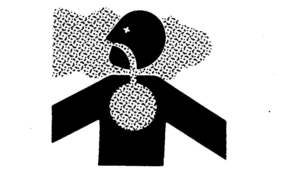
AvoidHarmfulAsbestosDust
Avoidbreathingdustthatmaybegeneratedwhen handlingcomponentscontainingasbestosfibers.Inhaled asbestosfibersmaycauselungcancer.
Componentsinproductsthatmaycontainasbestosfibers arebrakepads,brakebandandliningassemblies,clutch plates,andsomegaskets.Theasbestosusedinthese componentsisusuallyfoundinaresinorsealedinsome way.Normalhandlingisnothazardousaslongas airbornedustcontainingasbestosisnotgenerated.
Avoidcreatingdust.Neverusecompressedairfor cleaning.Avoidbrushingorgrindingmaterialcontaining asbestos.Whenservicing,wearanapprovedrespirator.A specialvacuumcleanerisrecommendedtoclean asbestos.Ifnotavailable,applyamistofoilorwateron thematerialcontainingasbestos.
Keepbystandersawayfromthearea.
DX,DUST–19–15MAR91–1/1
3.RemovelocknutusingJDG666spannerwrench.
4.Removegearfromhousing.
5.Inspectparts.Repairasnecessary.
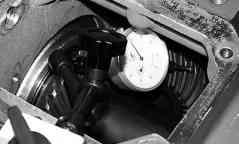
PreloadHydrostaticPumpDriveBearings
1.Assemblekeyedwasheroverhubofspiralbevelgear andnexttobearingcone.
2.ScrewlocknutusingJDG666SpannerWrenchonto spiralbevelgearhubwithchamferedsideagainst keyedwasher.Tightennuttospecificationtoprovide endplayinbearing.
Specification
HydrostaticPumpDriveGear— EndPlay0.33to0.43mm (0.010to0.020in.) +1/4turntopreload
3.Rapeachendofgearlightlywithsofthammerand rotategearatleastfiverevolutionsbeforetakingend playorrollingtorquemeasurements.Tightennut90 degrees(1/4turn).
4.Assemblelockwasheroverhubofspiralbevelgear withconcavesideoutward.Ifnowashertabalignswith aslotinnut,tightennuttonearestslotalignment.
5.InstalllocknutusingJDG666SpannerWrenchwith chamferedsideagainstlockwasher.
6.Withnutsnugagainstwasher,bendonetabofwasher intoaslotofinnernut.Tightenouternutto specification.
Specification
HydrostaticPumpDriveOuter Nut—Torque70N•m (52lb-ft)
Rollingtorquemustnotexceedspecification.
Specification
HydrostaticDrivePump—Rolling DragTorque28N•cm (40oz-in.)
Ifrollingtorqueistoohigh,removeouternutandlock washerandbackoffinnernut45degrees(1/8turn). Repeatinstallationandadjustment.
Finalassemblymustprovidezeroendplayandlessthan 28N•cm(40oz-in.)rollingtorque.
7.Bendonetabtolockwasherintoslotofouternut.
SetHydrostaticPumpDriveGearBacklash
NOTE:Donotusemorethanoneplasticshim.
1.Selectshimstoprovidebacklash(dimensiononendof smallergearto+0.1to-0.0mm(+0.004to-0.0in.)at tightestconditionofgearmesh.
2.InstallshimsandO-ringonpilotdiameterofbearing housing.Tightencapscrewstospecification.
Specification
HydrostaticPumpDrive-to-Gear CaseCapScrews—Torque50N•m (40lb-ft)
Shimsavailableare:
• 0.08mm(0.003in.)
• 0.13mm(0.005in.)
• 0.25mm(0.010in.)
• 0.50mm(0.020in.)
AG,OUO6022,379–19–25JUL00–2/2
AG,OUO6022,380–19–25JUL00–1/1
EngineGearCaseandValve
DisassembleandAssembleOilScreen
NOTE:Whenevergears,shafts,orbearingshavebeen replaced,cleanoilscreen.
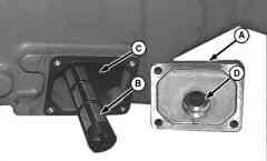
1.Removecover(A)withgasket.
2.Cleanoilscreen(B).
3.Thoroughlycleansumparea(C).
4.Installoilscreen.Besureclosedendofscreenfitsin recessonoppositeside.Pilot(D)mustbeDOWNto positionscreenlowinsump.Tightencoverboltsto specification.
Specification
EngineGearCaseOilScreen
CoverCapScrews—Torque25N•m (216lb-in.)
A—Cover B—OilScreen
C—Reservoir D—Pilot
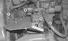
DisassembleandAssembleOilTrough
1.Removeoiltrough(A)withcover(B).
IMPORTANT:Correctlocknutsmustbeusedoncap screws(C).Standardnutsmaycome loose,fallintogearcaseandcause damage.
IMPORTANT:Becertaintroughisattachedtocover asshownoroilwillnotbedeliveredto bearings.
2.Replaceifdamaged.
3.Applyathinbeadofsealantallaroundsurface(D).
4.Installoiltrough.Tightencapscrewstospecification.
Specification
OilTroughCoverCapScrews— Torque25 ± 5N•m (221 ± 44lb-in.)
A—OilTrough B—Surface C—Cover D—Surface
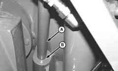
DisassembleandAssembleDipstickTube
NOTE:Removedipsticktubeonlyifdamaged.
1.Removedipsticktube(A).Tubeisatightfit.
2.Applyacoatofthreadlockandsealerinbore(B).
3.Driveintubeuntilitseats.
A—DipstickTube B—Bore
RemoveandInstallFilter
1.Turnfilter(A)counterclockwiseandremove.
2.Installfilter(A).
3.FillgearcasewithSAE10Woil.Filltocapacity.
AG,OUO6022,297–19–05AUG05–1/1
4.Checkoillevelafterengagingdrives.
OUO6083,0000075–19–21MAY01–1/1
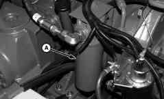
RemoveandInstallPressureRegulating Valve
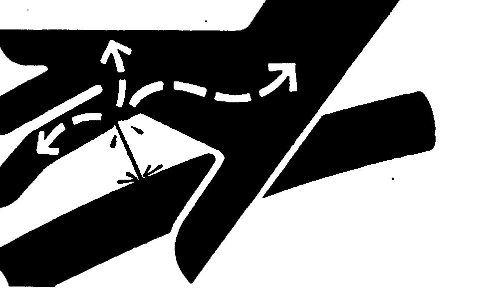
CAUTION:Escapingfluidunderpressurecan penetratetheskincausingseriousinjury.Avoid thehazardbyrelievingpressurebefore disconnectinghydraulicorotherlines.Tighten allconnectionsbeforeapplyingpressure. Searchforleakswithapieceofcardboard. Protecthandsandbodyfromhighpressure fluids.
Ifanaccidentoccurs,seeadoctorimmediately. Anyfluidinjectedintotheskinmustbe surgicallyremovedwithinafewhoursor gangrenemayresult.Doctorsunfamiliarwith thistypeofinjurymaycallDeere&Company MedicalDepartmentinMoline,Illinois,orother knowledgeablemedicalsource.
1.Fullylowerheaderandreeltogroundandcontinueto depressswitchfor5secondstorelievehydraulic systempressure.Shutoffengineandclose accumulator.Removekey.
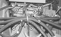
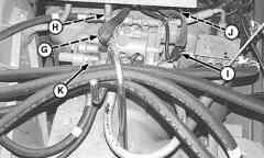
2.Disconnectlines(A—F).
3.Disconnectwiresleads(G—J).
4.Removecapscrews(K)andremovevalve.
5.Inspectforwearordamage.Replaceasnecessary.
NOTE:Donotusesealerongasket.
6.Installvalve.Tightencapscrewstospecification.
Specification
PressureRegulatingValveCap Screws—Torque25N•m (216lb-in.)
7.Connectwires(G—J).
8.Connectlines(A—F).
A—HydraulicHose
B—HydraulicHose
C—HydraulicHose
D—HydraulicHose
E—HydraulicHose
F—HydraulicHose
G—Connector
H—Connector
I—Connector
J—Connector K—CapScrews(7used)
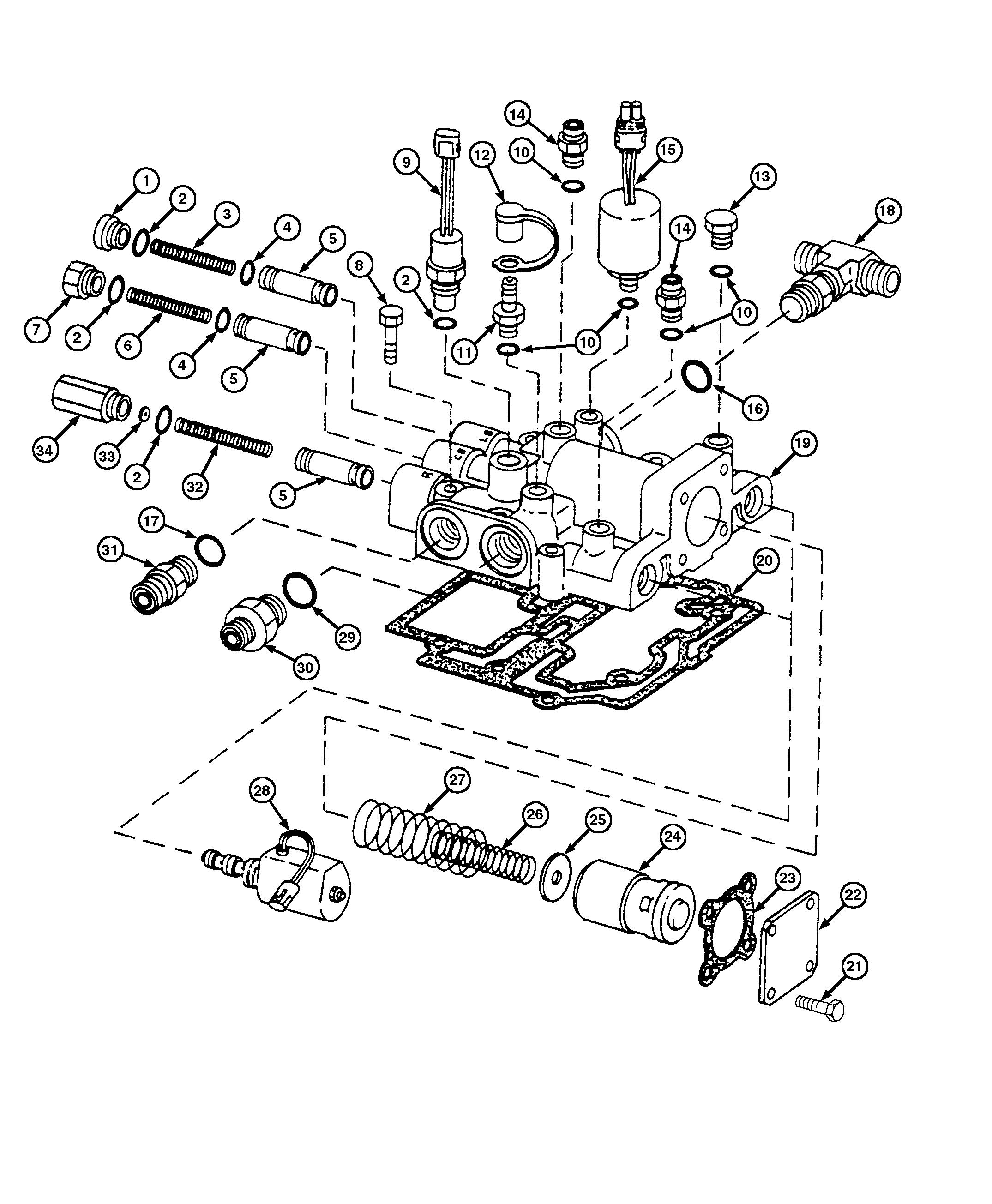
1—Plug10—O-Ring19—ValveHousing27—Spring 2—O-Ring11—TestGaugeFitting20—Gasket28—Solenoid(2used) 3—Spring12—DustCap21—CapScrew(4used)29—O-Ring 4—O-Ring13—Plug22—Cover30—Adapter 5—Valve(3used)14—Adapter23—Gasket31—Adapter 6—Spring15—OilPressureSender24—AccumulatorPiston32—Spring 7—Plug16—O-Ring25—Washer33—Shim 8—CapScrew(7used)17—O-Ring26—Spring34—Fitting 9—WetClutchOilTemperature18—Tee Sender
1.Refertotheexplodedviewfordisassemblyand assembly.
2.Washpartsinsolventanddrythoroughly.
3.Removesmallnicksandburrswithemerycloth. Replacepartsasneeded.Repairkitsarenot available.
NOTE:O-ringsareusedonallspoolsexceptspoolin port“R”.DonotuseanO-ringonspoolinport “R”.
4.Insertcrossdrilledholesonvalves(5)intohousing first.
5.Replacesamequantityofshims(33)thatwere removed.Theyarepre-setatthefactory.However, ifvalvehousing(19)isreplaced,installoriginal shimsandcheckregulatedpressure.Addshimsas necessary.Eachshimwillincreasethepressureby approximately10psi.
6.Temperaturesender(9)goesintoport“TI”. Pressuresender(15)goesintoport“PI”.
Continuedonnextpage
OUO6083,00005C3–19–14MAY03–2/4
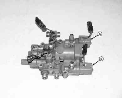
A—SeparatorSolenoidB—UnloadingSystem Solenoid
7.Thetwosolenoidsareidentical;(A)engagesthe separatorand(B)engagestheunloadingsystem. Refertotheexplodedviewforrepair.Tightenlarge hexwheninstallingsolenoidcartridgeto specification.
Specification
PressureRegulatingValve SolenoidCartridge—Torque25N•m (216lb-in.)
H57022–UN–24JUN99
8.Donotuseasealerongaskets(20)and(23). Tightenthesevencapscrewstospecification.
Specification
PressureRegulatingValveCap Screws—Torque25N•m (216lb-in.)
OUO6083,00005C3–19–14MAY03–3/4
A—Back-upRingE—SnapRingI—PlungerL—guide B—O-RingF—SpoolJ—SpringM—Nut C—Back-upRingG—SpringPinK—O-RingN—Coil D—O-RingH—O-Ring
OUO6083,00005C3–19–14MAY03–4/4
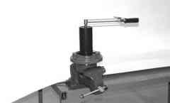
ValveSolenoid
A—65 ± 2mm(2.559 ± 0.079B—65 ± 10mm(2.559 ± 0.394E—105 ± 10mm(4.134 ± 0.394G—53 ± 2mm(2.087 ± 0.079 in.)in.)1 in.)in.)
C—96 ± 1mm(3.78 ± 0.039in.)F—33 ± 2mm(1.299 ± 0.079H—55mm(2.165in.)
D—125 ± 5mm(4.921 ± 0.197)in.)Maximum2
MaterialRequired:
IMPORTANT:Steelmustbe1045FCDQL-2or harder.
NOTE:ODoftoolmustbeaminimumof125mm (4.921in),butmaybelarger.
165mm(2.559in.)istheMAXIMUMODallowedtomaintainproper sidewallthickness.ODmaybemadesmallerthan65mm(2.559 in.).Diametershouldmatchpresscylinderdiametertoaidin centeringtooloverbearing.
255mm(2.165in.)istheMAXIMUMdepthoftopboretomaintain properthickness.Topboredepthmaybelessthan55mm(2.165) butmustbeaMINIMUMof5mm(0.197in.)deep.
• 125mm(4.921in.)RDJDMA01045FCDQL-2 Steel
Augerswingvalvemodule
Automaticcombineadjustmentdisplay
AuxiliarycabmainAUTOTRACwiring
Auxiliaryfieldlights
Axlebearingsandseals
Axleextensiontubes
Cleangrainelevator
Bladeinserts
Removeradiator
9.0L...........................
Crossaugercountershaftshearbolt
Cylinderblock
Dischargebeaterhousing
9.0L...........................
Separatordrive
Evaporator
Disassembleandassemble ......... 140-05-56 Replace Preloadbearings 140-05-59
Separatordrivewetclutch
Separatorgear
Transfergearcase
Disassembleandassemble
Evaporatortemperaturesensor
Exhaustgasrecirculation(EGR)mixedgas
CONTOURMASTERtiltbeam
CONTOURMASTERtiltframe
Conveyor
Foldingaugerrings
Foldinghorizontalauger
Freshairtemperature
FrontHorizontalunloadingauger
Horizontalunloadingaugerandgearcase
Electro-hydraulicfeederhousereverservalve
Hydraulicsolenoidcontrolvalve
Pilotsleeveo-rings
HubIdentification 70-16-8
Twowayreelliftandvariablespeedfeeder
Hydrauliccylinders(S.N.715301--)
(S.N.--715300)
HydraulicpumpSpecifications 70-05-2 Temperaturesensor Assemble 70-10-9 Disassemble 70-10-5Removeandinstall 40-35-16 TierIIIcoolingpacakge 40-35-16 Essentialorrecommendedtools 70-10-1
Accessdoorworklight,bulb
Auxiliaryfieldworklight,bulb
Light,(InfraRed)
Lowshaftspeedsensor
Lowercellassembly GREENSTARmoisturesensor Removeandreplace 40-60-11
Lowerenginerepair RemoveandinstallengineoilpanaccessOilscreen Disassembleandasssemble .......... 140-05-65 sheet ............................20-15-1 LowergearcaseOiltrough Disassembleandassemble 140-05-65
Verticalauger Install 130-15-12Operatingspeeds 9560combine 10-10-3 Remove 130-15-3 Lubricant9660STS,9670STS 10-10-9 9860Combine 10-10-18 Mixing 10-20-17 Storage 10-20-16Operatorsseat Airsuspensionexplodedview 90-15-46
Lubricityofdieselfuel 10-20-4
Essentialorrecommendedtools 120-30-1
Receiver/dryer
Othermaterial 120-30-1 Removeandinstall ...................90-10-4 Removeandinstall .................. 120-30-3
Recirculatorfanmotordriver Specifications 120-30-2 Removeandinstall
Reel/belt
Reelfore/aftvalvemodule .............. 70-16-10
Reel/beltpickup Strawspreader Explodedview 70-10-11 Flowcontrolvalve Reel/beltpickup
Radiator
Reel/beltpickupdrive Disassembleandassemble ........... 70-10-15 R
Reel/beltpickuppump Assemble ......................... 70-10-23
Reel/beltpickuppumpdrive Install 12.5L 20-10-28Removeandinstall 70-10-12
TurbochargerCompressorInlet sieveframe
Shoesupplyaugers,cleaningfanandchafferand
Removeandinstall Fanspeedactuator
Sensors
Threshingbars
Separatorgear
Tierodend
Strawspreader
Warningdisplaypanelandheaderfloatgaugelights