
793D OFF-HIGHWAY TRUCKS
INTRODUCTION
CONTENT
This presentation provides new and different New Product Introduction (NPI) information for the 793D Off-highway Truck. This presentation may be used for self-paced and self-directed training.
OBJECTIVES
After learning the information in this presentation, the technician will be able to:
1.locate and identify the new components;
2.explain the operation of the new components in the systems; and
3.trace the flow of oil or air through the new systems.
REFERENCES
“793C Off-Highway Truck, (4AR, 4GZ, ATY) Comparison Information”Download “793C Update (4GZ, ATY) Off-Highway Truck” SERV1722
Estimated Time: 8 Hours
Visuals: 59
Handouts: 1
Form: SERV7106-08
Date: 08/06
© 2006 Caterpillar Inc.
TABLE OF CONTENTS
793D OFF-HIGHWAY TRUCK
INTRODUCTION
INTRODUCTION
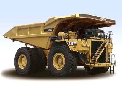
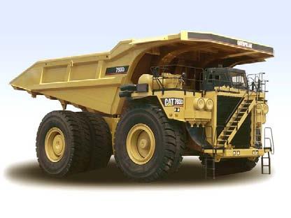
Shown is the right side of a 793D Truck. The 793D has a redesigned hydraulic system, an improved cooling package, an extended life power train, and a number of other changes to be covered in this presentation.
The machine weights, the payload ratings, the altitude derate, and the fuel efficiency will not change.
The following items are key new features:
- increased speed
- Extra retarding
- Continuous rear axle filtration
- Horsepower increase
- Improved cooling package
- Extended wheel station life
- Hydraulically driven engine coolant fan
- Steering hydraulic system changes
NOTE: The "HYDRAULIC SCHEMATIC COLOR CODE" is located after the "CONCLUSION" of this presentation.
Caterpillar Inc.
The following specifications are for the 793D Truck (dual slope body, no liners):
-Serial No. Prefix: FDB
-Empty weight: 144651 kg (318895 lbs.)
-Load carrying capacity: 218 metric tons (240 tons)
-Gross Machine Weight (GMW): 376488 kg (830000 lbs.)
-Length: 12.9 m (42.2 ft.)
-Width: 7.4 m (24.3 ft.)
-Height: 6.4 m (21 ft.)
-Gross Power: 1800 kW (2415 hp)
The 793D is available in four different normal altitude configurations, and a high altitude arrangement. All configurations deliver increased speed on grade and include key components that are performance matched to the hauling application and site conditions. The following list explains the five arrangements:
Standard (MA1) (246-6735) - The standard arrangement is designed for exceptional, all-around performance. Three factors combine to produce up to 9% more power at the wheels than the 793C, including; 5% more engine horsepower; a common rail hydraulic system for greater power train efficiency; and a hydraulically driven demand fan that reduces parasitic load by operating only when needed. More power at the wheels reduces cycle times and lowers cost-per-ton.
Extra Retarding (MA2) (246-6736) - Developed for downhill loaded applications. This configuration typically delivers an extra gear of retarding capability of 35% more speed on downhill grades. Extra retarding is achieved by adding more robust wheel groups, larger brakes, extended life friction material, and additional cooling capacity.
Extra Top Speed (MA3) (246-6737) - Developed for long, flat haul applications. The extra top speed configuration delivers a 10% increase in maximum speed to 60 km/h (37 mph) via a new input transfer gear group. This arrangement also includes Extended Life Wheel Groups.
Extended Life Wheel Groups (MA4) (246-6738) - Developed for uphill hauling applications. This arrangement is designed to extend wheel life and hauling performance on long uphill hauls. Extended life wheel groups are built with larger, more durable components, including larger spindles, wider wheel bearing spacing, a larger braking surface, and extended life friction disc material for longer brake life and more time between overhauls.
High Altitude (MA5) (246-6739) - Developed for high altitude applications. The 3516B short stroke engine delivers enhanced power management at higher altitudes from 2750 to 4000 m (9,000 to 12,000 ft). This arrangement also includes "Extra Retarding."
8, No.1, 2006
SIMILARITIES AND DIFFERENCES
Similarities and Differences
The chart above shows the similarities and differences between the earlier 793C Off-highway Truck and the updated 793D Off-highway Truck.
ENGINE
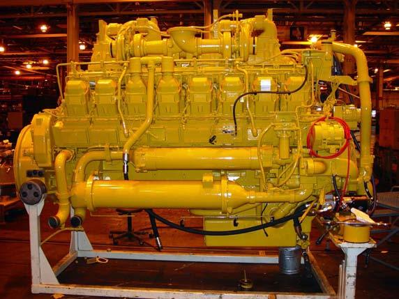
Shown is the right side of the 3516B Engine equipped with the Electronic Unit Injection (EUI), that is used in the 793D Off-highway Truck. The following items are the changes to the engine:
-5% Gross Power increase to 1800 kW (2415 hp)
-25% More Water Flow for Retarding
-Machine-mounted Hydraulically Driven Coolant Fan
-Air Cooled Engine ECM
-Relocated A/C Compressor
The engine performance specification for the 793D Truck is:
-Serial No. Prefix: 8WM
-Performance Spec: 0K5567
-Max Altitude: 2591 m (8500 ft.)
-Gross Power: 1800 kW (2415 hp)
-Full Load rpm: 1750
-High Idle rpm: 1960 ± 40
-Low Idle rpm: 700 ± 15
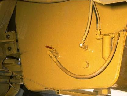
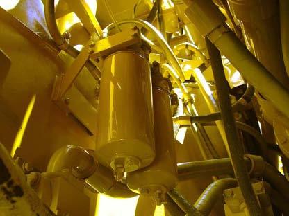
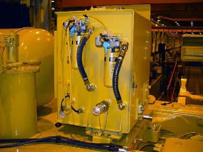
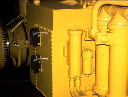
Shown in the top visual is the primary fuel filter (1) on the 793C. This filter is mounted on the back side of the fuel tank. Fuel is pulled through the filter by the fuel transfer pump which is mounted on the right side of the engine.
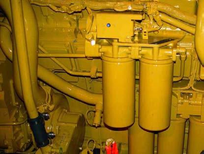
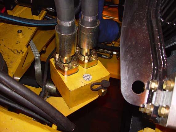
The 793D, shown in the bottom visual, has two optional fuel/water separators (2) in place of the single primary filter as on the previous machine. These filters are mounted inside the right frame rail adjacent to the engine. A valve located on the bottom of the filter provides a means to drain water that has separated from the fuel.
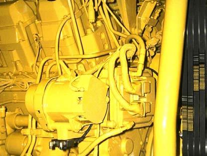
The top visual of the 793C shows the Engine ECM (1) located on the right front corner of the 3516B. Fuel flowing through the hose (2) is used to cool the Engine ECM. Fuel flows from the fuel transfer pump through the Engine ECM to the secondary fuel filters.
The bottom visual shows the Engine ECM (3) on the 793D located on the left side of the engine. The Engine ECM (3) is air cooled, therefore the absence of fuel lines for cooling can be noted.
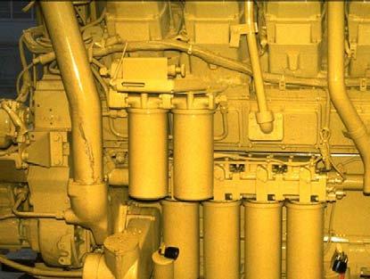
The 793C secondary fuel filters (1), engine oil filters (2), and engine oil dipstick (3) are shown in the top visual.
The 793D secondary fuel filters (4), engine oil filters (5), and engine oil dipstick (6) are shown in the bottom visual. The filters have been moved rearward one cylinder position. The engine oil dipstick has been moved to the center position on the engine oil pan.
8, No.1, 2006
Hydraulic Cooling Fan
The fan is hydraulically driven. A variable displacement piston-type pump provides oil flow to the fixed displacement motor. The hydraulic motor turns the fan blades. After flowing through the steering/fan cooler, the oil returns to the steering tank.
If supply oil to the fan stops suddenly, the fan and fan motor may continue to rotate because of the mass of the fan. The makeup valve allows oil to flow from the return side of the circuit to the supply side to prevent a vacuum in the supply lines.
The fan speed is determined by the amount of flow from the fan pump since the fan motor is a fixed displacement motor. The fan pump, which is a variable displacement pump, has a displacement solenoid that is controlled by the Brake ECM. Controlling the solenoid current subsequently controls the fan speed The output to the solenoid is determined by the following inputs:
• Transmission lube temperature• Engine aftercooler temperature
• Torque converter lube temperature• Ground speed
• Brake temperature• Engine coolant temperature
• Brake cooling pump speed sensor• Engine cooling fan speed sensor
Vol. 8, No.1, 2006
The cooling logic on the 793D controls two systems: the engine cooling fan system and the brake cooling system. The cooling logic requests temperature information from various controls over the CAT data link. This information is combined to determine the desired engine cooling fan speed and the desired brake cooling motor speed.
The engine cooling fan and the brake cooling motor could be ON, OFF, or MODULATED based on feed back to the Brake ECM. The cooling logic has the following modes of operation:
NO COOLING
Both the engine cooling fan and the brake cooling motor are turned OFF. They are both turning at minimum speed.
MODULATED COOLING
The engine cooling fan is modulated. If the brake temperatures are not high (hot) enough, then the brake cooling motor is modulated, as well. The brake diverter solenoid is de-energized.
BRAKE COOLING
The engine cooling fan and the brake cooling motor at at maximum speed. The brake diverter solenoid is energized.
OTHER COOLING
Only the engine cooling fan is at maximum speed. The brake cooling motor is at minimum speed and the brake diverter solenoid is de-energized.
FULL COOLING
The engine cooling fan is at maximum speed. The brake cooling motor is at maximum speed and the brake diverter solenoid is energized, as well.
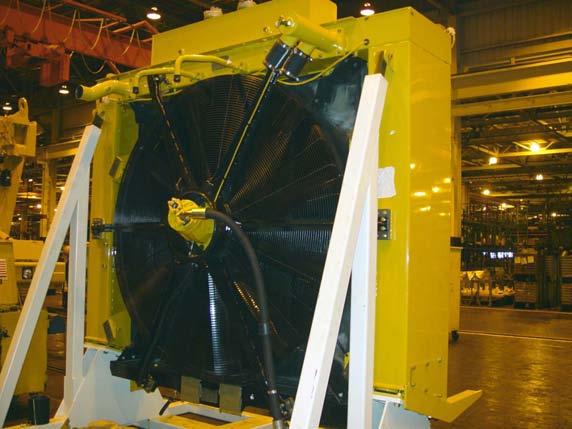
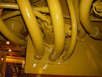
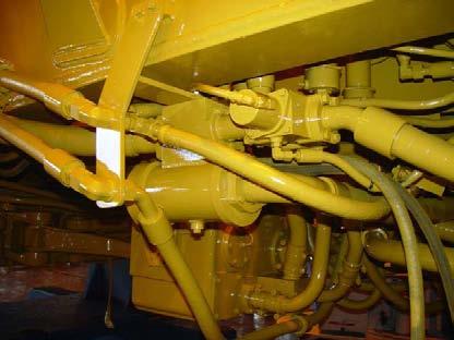
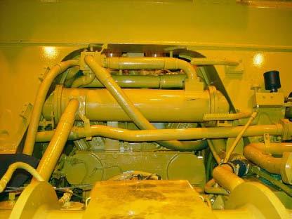
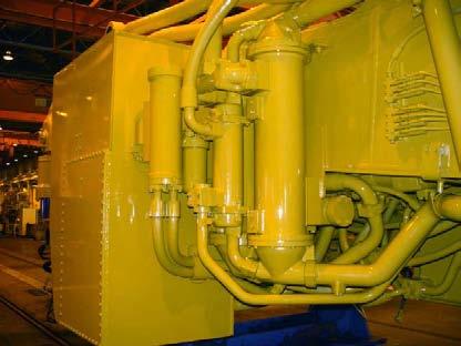
Shown is the 793D truck radiator module. The shunt tank (1) can be seen on top of the radiator. Two smaller tubes (2) below the shunt tank provide a coolant supply to the jacket water pump and the aftercooler water pump. Most of the coolant flows to these two pumps from the radiator through two large tubes at the bottom of the radiator (not shown). Coolant returns to the radiator through the large tubes (3) in the radiator top tank. Coolant is supplied to the shunt tank (1) from the radiator top tank through some small hoses below the shunt tank (not shown).
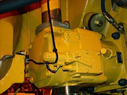
The fan drive pump (1) is mounted to the front of the pump drive. The pump drive is located on the inside of the right frame rail. The Brake ECM controls the flow of oil from the fan drive pump by energizing the displacement solenoid (3). The pressure and flow compensator (2) contains the high pressure cut-off valve (4). The high pressure cut-off is an adjustable valve that controls the maximum pressure in the cooling fan system.
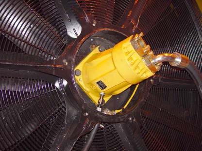
The fan drive motor (5) is mounted to the fan shroud behind the radiator. The fan speed sensor (6) is an input to the Brake ECM. The Brake ECM uses this input to match the fan speed to the proper cooling load.
Shown is the fan makeup valve (1). The fan makeup valve is located behind the lower right section of the radiator.
If supply oil to the fan stops suddenly, the fan and fan motor may continue to rotate due to the mass of the fan. Continued rotation of the fan motor would create a vacuum in the supply circuit between the fan pump and the fan motor. The fan makeup valve allows oil to flow from the return side of the circuit to the supply side to prevent a vacuum.
The fan drive pressure tap (2) is used to measure fan pump pressure. Fan pump pressure is adjusted at the high pressure cut-off valve on the fan pump. The pressure will vary depending on the desired fan speed controlled by the Brake ECM.
793C REAR AXLE
OIL COOLING AND FILTER SYSTEM
Oil Cooler Oil Filter
Temperature and Flow Control Valve
Temperature / Pressure Control Valve
Differential Oil Pump
Suction Screen
REAR AXLE COOLING AND FILTER SYSTEM
Shown is a schematic of the rear axle oil cooling and filter system for the 793C. The differential oil pump pulls oil from the bottom of the rear axle housing through a suction screen. Oil flows from the pump through a temperature and flow control valve located on top of the differential housing.
The temperature and pressure control valve, which is part of the temperature and flow control valve, prevents high oil pressure when the rear axle oil is cold. When the oil temperature is below 43° C (110° F), the valve is OPEN and allows oil to flow to the rear axle housing. When the oil temperature is above 43° C (110° F), the valve is CLOSED. The oil flows through the differential oil filter and the oil cooler (if equipped) to a flow control valve, which is also part of the temperature and flow control valve.
The temperature and pressure control valve is also the system main relief valve. If the pressure exceeds 690 kPa (100 psi), the temperature and pressure control valve will open to prevent high oil pressure to the oil filter.
The flow control valve distributes the oil flow to the rear wheel bearings and the differential bearings. At high ground speeds, excess oil flow is diverted to the axle housing to prevent overfilling the wheel bearing and final drive compartments.
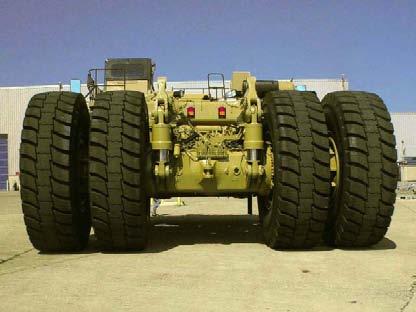
Rear Axle
793D REAR AXLE LUBRICATION
The 793D has a continuous rear axle lubrication system. The system does not require that the truck be moving to provide flow, so the flow can be adjusted according to current conditions.
The engine driven steering pump supplies oil to the priority valve. The Brake ECM controls the supply valve based on the combination of feedback from a temperature sensor mounted in the bango housing and some basic information about the state of the machine. When the supply solenoid is de-energized, oil flow is directed to the rear axle (RAX) pump motor. When the supply solenoid is ON, oil flow is blocked to the RAX pump motor.
The RAX pump motor drives the RAX pump sending flow first to the RAX oil filter and then the final drive bypass manifold. If the machine is equipped with the auxiliary cooler, oil flows through the oil cooler before flowing to the bypass valve. An optional cooling fan is used to reduce the temperature of the lube oil.
The bypass solenoid valve either sends oil to both the final drive and the differential bevel gear, or bypasses the final drives. This bypass strategy prevents the final drives from receiving too much oil flow under certain conditions. The tubes to the final drives and bevel gear contain an orifice to balance flow throughout the system.
8, No.1, 2006
REAR AXLE LUBRICATION STRATEGY
Shown in this visual is the rear axle lubrication strategy for the 793D.
The main input that the Brake ECM uses to control the rear axle lube system is the temperature of the rear axle oil. This temperature, along with some basic information about the state of the machine, such as ground speed and engine speed, allows the Brake ECM to energize the rear axle supply solenoid and the final drive bypass solenoid. By energizing these two solenoids, the lube system can be turned ON or Off.
During startup, the system is turned ON to charge the lube system. There is no advantage to lubing the rear axle due to the high viscosity of the cold oil. Therefore, the system is turned OFF after 5 minutes when the lube oil is cold. If the machine is traveling greater than 22 mph, the lube to the final drives is cycled ON and OFF. This cycling prevents filling the final drives due to centrifugal force by keeping only a small amount of oil in the final drives.
The temperature gear limit is used to limit the actual transmission gear to keep the machine from doing any high speed traveling until the differential oil has warmed up enough for the lube system to be effective.
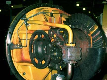
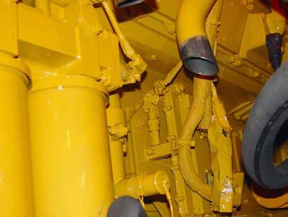
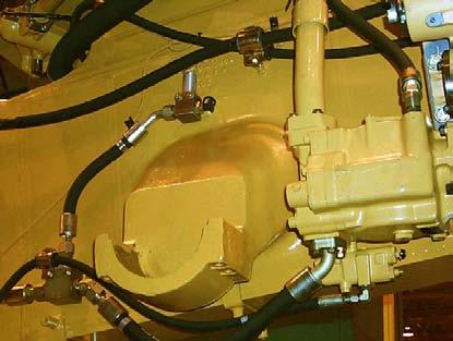
Shown in the top visual is the 793C rear axle oil pump (1) that is driven by the differential. The differential is removed from the differential housing. Since the pump rotates only when the machine is moving, no oil flow is produced when the machine is stationary.
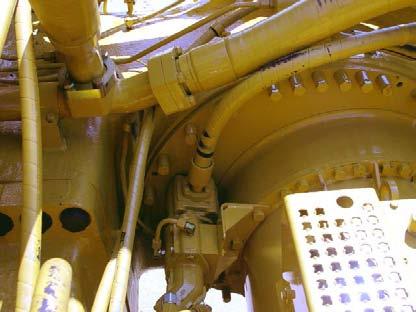
The pump drive motor (2) and the lube pump (3) for the 793D continuous rear axle lubrication system is shown in the bottom visual. This system provides a more consistent oil supply to wheel bearings and final drive assemblies providing longer component life.
STEERING SYSTEM
STEERING SYSTEM
This section of the presentation explains the operational changes in the steering system. The steering system uses hydraulic force to change the direction of the front wheels, similar to other Caterpillar off-highway trucks. The system has no mechanical connection between the steering wheel and the steering cylinders.
If the flow is interrupted while the truck is moving, the system incorporates a secondary steering system. Secondary steering is accomplished by accumulators which supply oil flow to maintain steering.
The steering cylinders, the steering valve, the solenoid and relief valve manifold, and the Hand Metering Unit (HMU) remain unchanged. The main changes involve the steering pump and the method of maintaining pressure in the steering system.
8, No.1, 2006
793C STEERING SYSTEM
The steering system for the 793C in a no-turn situation is shown in this visual.
The steering pump receives oil from the steering tank located on the right side of the operators platform. Oil then flows to the solenoid and relief valve manifold located on the front frame cross member. The oil flow is then sent to the accumulators and the accumulator charging valve. The steering accumulators store hydraulic energy for the steering system. The accumulator charging valve controls the CUT-IN and CUT-OUT pressure for the steering pump. Once the steering accumulators are charged, the system will be in low pressure stand-by.
The solenoid and relief valve manifold also sends oil to the steering control valve. This valve controls the flow of oil to the steering cylinders which turn the front wheels and control the direction of the truck. The hand metering unit (HMU), which is connected to the opposite end of the steering column, directs pilot oil back to the steering control valve when the operator turns the steering wheel. This action causes the steering control valve to send oil to the steering cylinders to make a steering correction.
A small amount of oil continuously flows through the HMU back to the tank to keep the HMU at the same temperature as the rest of the steering system. All oil returning to the tank first flows through a return filter mounted inside the steering tank.
793D STEERING SYSTEM NO TURN
The above block diagram shows the steering system for the 793D. Although there are many similarities between this system and the previous system, there are several significant changes, as well.
The steering pump receives oil from a larger steering tank mounted on the operator’s platform. Oil then flows to the priority valve. Flow is first used to satisfy the steering system. Once the steering system is satisfied, the priority valve allows flow for other systems such as the RAX motor and the brake cooling drive motor.
The components downstream of the priority valve operate the same as previously discussed on the 793C. A steering oil cooler has been added for oil returning to the steering tank. The steering tank also provides flow for the hydraulic fan pump.
The 793D steering system operates at maximum pressure, but minimum flow, once the demand of the system is met. On the 793C a signal was sent back to the steering pump (load sensing system) to put the pump in a low pressure and minimum flow state. The 793D is not a load sensing system.
Steering Cooler
Steering Pump
Steering Tank
Hand Metering Unit
Steering Control Valve
Steering Cylinders
Solenoid and Relief Valve Manifold
Priority Valve
To Brake Cooling Motor
Fan Pump
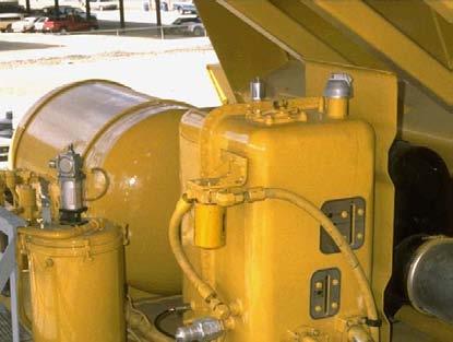
The 793C steering tank is located on the right platform. This tank provides oil to a piston-type pump through a hose (1). Case drain oil from the steering pump returns to the tank through the filter (2). The remaining steering oil returns to the tank through the main steering filter (3).
The bottom visual shows the steering tank on the 793D. This tank supplies oil to the steering system, the engine cooling fan motor, the brake cooling oil drive motor, the RAX motor, and the RAX fan motor, if equipped. Due to the many systems being supplied, the tank is a higher capacity tank than the previous steering tank. Two case drain filters filter the return oil from the various piston motors and pumps. Case drain oil from the common rail hydraulic system returns through the filter (4). Case drain oil from the fan drive system returns through the case drain filter (5).
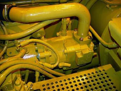
The top visual shows the 793C pressure compensated, piston-type pump (1). The steering pump contains a load sensing controller (2) that works with an accumulator charging valve to monitor and control steering pump output. When pressure in the accumulators decreases (CUT-IN), the pump upstrokes and charges the accumulators until the CUT-OUT pressure is reached.
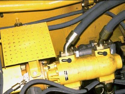
Shown in the bottom visual is the steering pump (3) for the 793D. This pump is mounted on the backside of the pump drive behind the torque converter housing. Oil is supplied to the pump through the tube (4) coming from the steering tank. Like the 793C, a load sensing controller (5) controls the pump output but without an external signal line. The pump supply is sent to the priority valve located on the upper frame, near the right front strut.
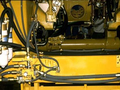
The solenoid and relief valve manifold (1) for the 793C, shown in the top visual, connects the steering pump to the accumulator charging valve (2), to the accumulators, and to the steering control valve (3). This valve also provides a path to drain for the steering oil. The accumulator charging valve controls the CUT-IN and CUT-OUT of the steering pump. This valve has been removed in the 793D steering system.
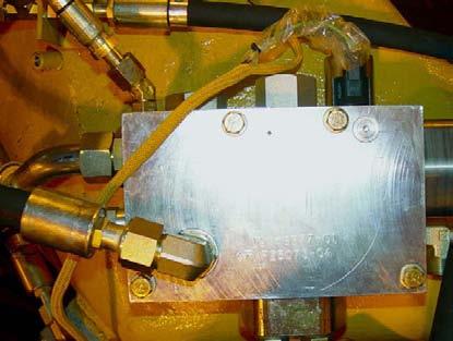
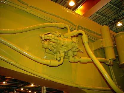
The bottom visual shows the priority valve manifold on the 793D. This manifold is located on the inside of the frame toward the rear of the truck. Oil from the steering pump enters the manifold through the hose (4). The manifold contains a priority valve which gives priority to the steering system.
8, No.1, 2006
The priority valve remains closed until the pressure in the steering system is 18615 kPa (2650 psi). the hose (5) allows the oil to flow to the accumulators via the solenoid and relief valve manifold.
Once the steering system requirements are satisfied, the priority valve opens and directs oil flow to the remaining systems supplied by the manifold. The hose (6) supplies oil to the drive motor for the brake cooling oil. Oil flows to the brake cooling drive motor whenever the priority valve is opened.
Oil flow from the hose (7) to the RAX motor and from the hose to the RAX cooling fan motor [behind (6)] are controlled by the solenoid valve (8). When the solenoid (8) is de-energized, the RAX motor and RAX cooling fan motor receive oil flow. When the solenoid is energized, flow is blocked to the RAX motor and the RAX cooling fan motor.
NOTE: The RAX cooling fan system is an attachment.
The hose (9) is a drain line and the hose (10) is connected to a pressure switch that monitors pressure in the steering system.
The priority manifold also contains a check valve that maintains pressure in the steering system when there is no flow from the steering pump. This allows the steering accumulators to maintain pressure for steering with a dead engine or in the event of a pump failure.
The remaining components; the steering control valve, the HMU, and the steering accumulators remain unchanged in function or operation between the 793C and 793D machines.
793D HYDRAULIC SYSTEM
Shown is the steering hydraulic system for the 793D Off-highway Truck.
The variable displacement steering pump sends flow to the priority valve manifold. The priority valve manifold contains a priority valve that opens at 18615 kPa (2650 psi). This feature allows the steering system to receive oil before the other systems that are supplied by the steering pump receive oil. Therefore, oil flows to the solenoid and relief valve to charge the steering accumulators first. The solenoid and relief valve contains a relief valve in the event that the high pressure cut-off fails to destroke the pump. Also contained in the solenoid and relief valve is an accumulator bleed-down solenoid. When the machine is shut down, the Brake ECM energizes this solenoid to relieve the pressure stored in the accumulators.
Once the steering system demands are met, the priority valve opens and sends oil flow to other systems connected to the priority manifold. The other systems include the brake cooling drive motor, the RAX motor, and the RAX cooling fan motor (if equipped). A solenoid valve mounted on the priority valve manifold controls the oil flow to the RAX system.
The priority valve manifold also contains a check valve for the steering system. If hydraulic flow is lost to the priority valve manifold, the check valve will prevent the steering accumulators from bleeding down. Subsequently, the truck will have steering even if the flow is interrupted.
793C BRAKE COOLING CIRCUIT
BRAKE COOLING SYSTEM
The 793C is equipped with three rear brake cooling pumps that pull oil from the hydraulic tank through suction screens. Rear brake cooling oil pressure is controlled by two oil cooler relief valves located inside the hydraulic tank. Oil flows from the rear brake cooling pumps through two screens and two brake oil coolers located behind the right front tire. Oil flows from the rear brake oil coolers, through the rear brakes, and then returns to the hydraulic tank.
The hoist pump and the parking brake release pump provide oil cooling flow for the front brakes. Front brake cooling oil pressure is controlled by an oil cooler relief valve located inside the hoist valve.
Oil flows from the hoist pump through two screens to the hoist valve. Most of the oil that flows into the parking brake release valve flows through the valve and joins with the hoist system oil. Oil flows from the hoist valve through the two front brake oil filters, the front brake oil cooler diverter valve, and the front brakes to the hydraulic tank.
Front brake cooling oil only flows through the front brake oil cooler if the service or retarder brakes (manual or automatic) are engaged.
On the 793D, the hoist pump and one section of the brake cooling pump combine to provide brake cooling oil flow for the front brakes. Brake cooling oil pressure is controlled by oil cooler relief valves located inside the hoist valve and inside the hoist tank.
Hoist oil flows through two hoist screens and a spin-on filter before reaching the diverter valve. The diverter valve sends oil through the brake cooling oil cooler, or diverts the oil around the cooler. Hoist oil only goes through the cooler when the service or retarder brakes are engaged. Oil coming from the brake cooling pump flows first through a screen and then through the brake cooler. Oil from this pump always flows through the cooler before going to the brakes and then returning to the hoist tank.
Rear brake cooling oil also comes from the hoist pump and a second section of the two-section brake cooling pump. Brake cooling oil pressure is controlled by oil cooler relief valves located inside the hoist valve and inside the hoist tank.
Hoist oil flows through hoist screens and a spin-on filter before joining with the oil from the second section of the brake cooling oil pump. This combined oil flows through two rear brake cooling oil screens and two brake cooling oil coolers. Oil then flows to the rear brakes and back to the hoist tank.
793D BRAKE COOLING CIRCUIT
The front brake cooling circuit on the 793C uses the hoist pump (1), shown in the top visual, as the source for oil flow when not required by the hoist system.
Shown in the bottom visual, the 793D two-section brake cooling pump is located inside the hoist hydraulic tank on the right side of the machine. This pump is driven by the brake cooling motor (2). The brake cooling motor is driven by oil flow from the priority valve which is supplied with oil by the steering pump.
The hoist screens (1) on the 793C and 793D are the same. Hoist oil enters the hoist valve through the two large hoses and exits the valve through brake cooling port (2). Oil flow through the hose (3), coming from the parking brake release valve, combines with the flow coming from the brake cooling port. This combined flow continues on to the front brake oil filters located on the left outside frame rail.
The diverter valve (4) on the 793D is located under the left frame rail. Normally, hoist oil flow in the hose (5) is diverted around the front brake oil cooler. When the brakes are applied, the air actuated diverter valve will allow hoist oil to combine with the front brake cooling oil in the hose (6) and flow to the front brake oil cooler. The screen (7) for the front brake cooling oil can be accessed by removing a cover.
The top visual shows the brake cooling oil filters (1) on the 793C. Oil coming from the hoist valve is filtered and then sent on to the front brake oil cooler.
The bottom visual shows the front brake and the rear brake cooling oil filters (4). The oil flowing to these two filters is coming from the hoist valve. The hose (3) is going to the diverter valve described on the preceding page. Since the hoist system and the brake cooling system draw oil from the same tank, all the oil will at some point be filtered.
Also shown in this view is the S•O•S tap (2) for testing the condition of the oil.
The diverter valve (1) on the 793C is located on the inlet port of the front brake oil cooler. The diverter valve on the 793C performs the same function as on the 793D described previously. After flowing through the cooler or diverting around the cooler, the oil flows to the front brakes and then back to the hoist hydraulic tank.
The brake cooling oil on the 793D flows from the front brake cooling screen through the hose (4), through the cooler, and then to the junction block (2). The hose (3) contains oil coming from the hoist valve when bypassing the front brake oil cooler. This hose is also connected to the junction block (2). After leaving the junction block, the oil flow splits and is directed to the front wheel brake packs. The oil circulates through the front brake packs to cool and lubricate and then returns to the hoist hydraulic tank on the right side of the machine.
Shown in this visual is the auxiliary brake oil cooler (arrow) for the 793D that is used on the Extra Retarding Arrangement. The brake oil cooler is mounted behind the left front strut. If the machine is equipped with the additional retarding attachment, more brake cooling capacity is required. Oil flow branches from the front brake cooling oil screen, discussed previously, to this cooler. After leaving the cooler, the oil flows to the manifold mounted above the front brake oil cooler and then to the front brake packs.
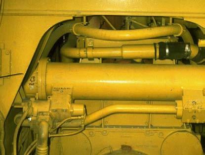
The three brake cooling oil pumps (1) for the rear brake cooling circuit on the 793C mount behind the brake release pump. Oil flows through the two screens (2) and the two rear brake oil coolers (3) to the rear brake packs.
On the 793D, a two-section brake cooling oil pump is mounted inside the hoist hydraulic tank. The brake cooling oil pump is driven by the brake cooling oil motor (4). This motor is electronically controlled by the Brake ECM. Oil flows from one section of the pump through two screens (not shown) to two rear brake oil coolers (5) and then to the rear brake packs.
Shown in the top visual are the rear brake cooling oil coolers (1) for the 793C. Oil flows from the coolers to the rear brake packs and returns through a port on the backside of the hoist hydraulic tank.
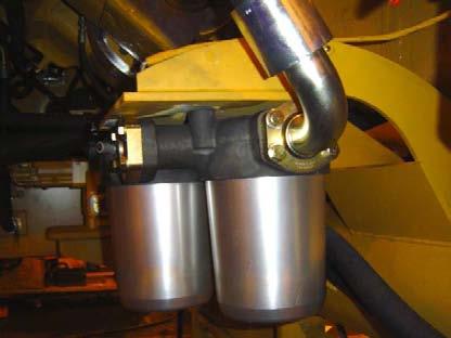
The bottom visual shows the rear brake cooling oil coolers (2) for the 793D. Oil flows through the screens (3), through the coolers, and then to the rear brake packs. Oil returns through a port on the back side of the hoist hydraulic tank.
Also shown is an additional return oil cooler (4). Return oil from the brake cooling oil motor and other motors flow through this cooler before returning to the steering tank.
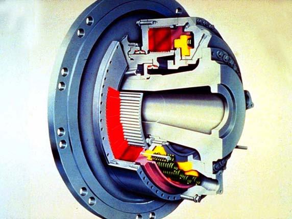
Shown is a cutaway illustration of an oil cooled brake assembly. The brakes are environmentally sealed and adjustment free. Oil continually flows through the brake discs for cooling.
Duo-Cone seals prevent the cooling oil from leaking to the ground or transferring into the axle housing. The wheel bearing adjustment must be maintained to keep the Duo-Cone seals from leaking.
The smaller piston (yellow) is used to ENGAGE the secondary and parking brakes. The parking brakes are spring ENGAGED and hydraulically RELEASED.
The larger piston (purple) is used to ENGAGE the retarder/service brakes. The retarder/service brakes are engaged hydraulically by an air-over-oil brake system.
SERVICE / RETARDER BRAKE AIR SYSTEM
AUTOMATIC RETARDER CONTROL (ARC)
This 793C block diagram shows the flow of air through the service/retarder air system when the ARC is ENGAGED, and the service brakes are RELEASED. Supply air pressure flows from the large service brake air tank to the relay valves, the service brake valve, the retarder valve, and the ARC valve
A series of check valves direct the air flow to the ARC relay valve. When the ARC brake system is ENGAGED, the ARC relay valve opens and metered air flows from the service brake tank to the front and rear brake cylinders.
Air pressure from the ARC valve also flows to the front brake oil cooler diverter valve which sends brake cooling oil through the front brake oil cooler.
Air from the ARC valve also flows to the retarder switch, the brake light switch, and the service/retarder brake switch. Engaging the ARC turns ON the retarder dash lamp, turns ON the brake lights, and also changes the transmission shift points and the anti-hunt timer.
Brake Cylinders
8, No.1, 2006
SERVICE / RETARDER BRAKE AIR SYSTEM
SERVICE BRAKES ENGAGED
Brake Light and Service / Retarder Switch Air Pressure Sensor
Service Brake Valve
Retarder Valve
Front Brake Cooler Diverter Valve
Service Brake Relay Valve
Primary Air Tank
From Air Compressor
From Secondary Air Reservoir
Brake Cylinders
With the introduction of the hydraulic ARC system on the 793D, several components have been removed from the brake air system.
Signal air from the primary air tank flows to the service brake valve and the retarder valve. A shuttle valve then sends the highest signal pressure to the service brake relay valve. The service brake relay valve opens allowing the brake cylinders to be actuated with air pressure from the primary air tank.
An addition to the air system is the cooling diverter solenoid for the front brake cooler diverter valve. Air is supplied to this valve from a smaller secondary air tank behind the cab. The Brake ECM energizes this valve when the service brakes are applied. When the Brake ECM energizes this solenoid, signal air is sent to the front brake cooler diverter valve to allow brake cooling oil to be sent through the cooler for front brake cooling oil.
Cooling Diverter Solenoid
Cab
793D HYDRAULIC ARC SYSTEM
ARC ENABLED
This 793D block diagram shows the flow of oil for the ARC system when ENABLED. Unlike the system on the 793C, this system is totally hydraulic.
Oil flow is provided by the parking brake release pump. The flow continues from the pump, through a check valve, to the ARC valve. The ARC valve modulates the amount of pressure to the service brakes in order to control the ground speed of the truck.
The air over hydraulic brake cylinders also use the service brakes. A shuttle valve between the ARC system and brake cylinders separates the two systems. Whichever system has the greatest pressure, that system will control the service brakes.
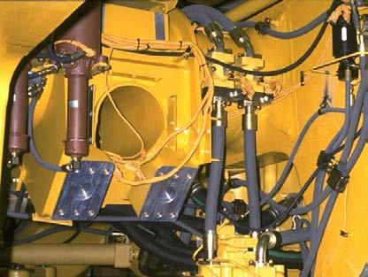
The top visual shows the 793C ARC valve located in the compartment in front of the cab. The ARC valve contains a supply solenoid valve (1), a control solenoid valve (2), and an auto retarder pressure switch (3). Located just below the ARC valve is the retarder pressure switch (4).
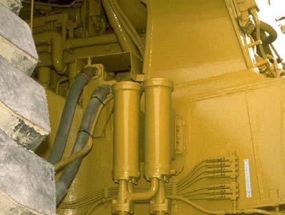
The 793D hydraulic ARC valve, located on the left frame rail near the rear differential, is shown in the bottom visual. This valve also contains a supply solenoid valve (5) and a control solenoid valve (6). A purge solenoid valve (7) is located on the bottom of the ARC valve. The ARC accumulator (8) is located to the right of the ARC valve.
NOTE: The hydraulic ARC valve performs the same functions as the air controlled ARC valve. The hydraulic ARC valve use oil pressure instead of air pressure, though.
HYDRAULIC ARC
ENGINE ON / ARC OFF
Control Solenoid Valve To Tank
Supply oil from the parking brake release pump flows across a check valve and enters the ARC valve. Hydraulic flow is stopped because the ARC spool is in the blocked position. Hydraulic flow is then directed to the accumulator to charge the accumulator to the same pressure as the parking brake release system pressure. Hydraulic flow is also routed through the supply solenoid valve to apply pilot pressure to the left end of the ARC spool. This pressure will keep the ARC spool in the blocked position.
Supply Solenoid Valve
Purge Solenoid Valve
Check Valve
Pump
Accumulator
ARC Spool To Service Brakes
HYDRAULIC ARC ENGINE ON / ARC ON
The Brake ECM supplies current to the supply solenoid. The supply solenoid valve sends pilot oil to the right end of the ARC spool. This pilot oil shifts the ARC spool to the left opening the left side of the ARC spool to tank. Simultaneously, pump supply oil is directed to the right side of the ARC spool. Pump oil is now directed to the control solenoid valve.
The Brake ECM will send varying levels of current to the control solenoid. This variable current will modulate the spool within the proportional valve. The level of current is dependent on the brake requirements for the ARC valve to maintain a constant braking force.
When the control solenoid is energized, the pin moves to the right and pushes against the ball. The ball restricts the amount of pump supply oil flowing to the drain. Pressure increases in the chamber to the left of the spool to move the spool to the right against the spring. When the spool moves to the right, pump supply oil is allowed to flow to the service brakes. In order to maintain the correct brake pressure, the Brake ECM will vary the current to the control solenoid to open and close the oil drain port.
HYDRAULIC ARC
The current that is supplied by the Brake ECM is removed from the supply solenoid when the engine and ARC are both OFF. This causes the supply solenoid valve to shift and all pilot pressure that was acting on the ARC spool is routed back to the tank. Current is supplied from the Steering Bleed Control to the purge solenoid valve which allows the pressure within the accumulator to drain back to the tank.
AUTOMATIC RETARDER CONTROL
This visual displays the interaction between the electronic components of the ARC system and the ARC valve on the 793C.
The ARC system function is to modulate truck braking (retarding) when descending a long grade to maintain a constant engine speed. The ARC system engages the service/retarder brakes. If the ON/OFF switch is moved to the ON position, the ARC will be activated if the throttle pedal is not depressed and the parking/ secondary brakes are RELEASED. The ARC system is disabled when the throttle is depressed or when the parking/secondary brakes are ENGAGED.
The ARC system is not connected to the service brakes, or to the manual retarder. When the ARC is ENGAGED, air flows from the ARC valve to a separate relay valve located near the brake master cylinders.
The ARC receives signals from several switches and sensors. The control analyzes the various input signals and sends signals to the output components. The output components are two solenoids and
Service Tool Connector
AUTOMATIC RETARDER CONTROL
Front Brake Cooling Diverter Solenoid From Parking Brake Release Pump
Steering Bleed Control
The introduction of the hydraulic ARC control valve on the 793D has required a number of additional component changes. The basic function of the new system remains the same as the previous system.
One of the new components, located in the compartment behind the cab, is the front brake cooling diverter solenoid. The Brake ECM energizes this solenoid when ARC is engaged to send an air signal to shift the brake cooling oil diverter valve. This will route the brake cooling oil through the front brake oil cooler for increased cooling. The brake cooling oil is routed around the front brake oil cooler, normally.
The steering bleed control is not a new component, but does serve an additional function. The steering bleed control is used to purge the ARC accumulator when the machine is shut down. When the control receives a signal from the key start switch, a timer built into the control will energize the purge solenoid for a period of time to purge the ARC accumulator.
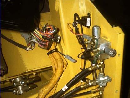
The steering bleed down control (1) is located in the compartment behind the cab.
The front brake cooling diverter solenoid (2) is located in the compartment behind the cab. This is a 24 V normally closed solenoid valve. When energized by the Brake ECM, signal air is sent to the front brake cooling diverter valve.
CONCLUSION
This presentation has provided New Product Introduction (NPI) information for the Caterpillar 793D Off-highway Truck. All new components and their locations were identified and discussed. When used in conjunction with the “793C Update Service Training Meeting Guide” (Form No. SERV1722) and the Service Manual, the information in this package should permit the serviceman to analyze problems in any of the major systems on these trucks.
Vol. 8, No.1, 2006
HYDRAULIC SCHEMATIC COLOR CODE
Black - Mechanical Connection. Seal
Dark Gray - Cutaway Section
Light Gray - Surface Color
White - Atmosphere or Air (No Pressure)
Purple - Pneumatic Pressure
Yellow - Moving or Activated Components
Cat Yellow - (Restricted Usage)
Identification of Components within a Moving Group
Brown - Lubricating Oil
Green - Tank, Sump, or Return Oil
Green / White StripesScavenge / Suction Oil or Hydraulic Void
Red - High Pressure Oil
Red / White Stripes - 1st Pressure Reduction
Red Crosshatch - 2nd Reduction in Pressure
Pink - 3rd Reduction in Pressure
Red / Pink Stripes - Secondary Source Oil Pressure
Orange - Pilot, Charge or Torque Converter Oil
Orange / White Stripes - Reduced Pilot, Charge, or TC Oil Pressure
Orange / Crosshatch - 2nd Reduction in Pilot, Charge, or TC Oil Pressure
Blue - Trapped Oil
HYDRAULIC SCHEMATIC COLOR CODE
This illustration identifies the meanings of the colors used in the hydraulic schematics and cross-sectional views shown throughout this presentation.
HYDRAULIC SCHEMATIC COLOR CODE
RedHigh Pressure Oil
Red / White Stripes1st Pressure Reduction
Red Crosshatch2nd Reduction in Pressure
Pink3rd Reduction in Pressure
Red / Pink StripesSecondary Source Oil Pressure
OrangePilot, Charge or Torque Converter Oil
Orange / White StripesReduced Pilot, Charge, or TC Oil Pressure
Orange / Crosshatch2nd Reduction in Pilot, Charge, or TC Oil Pressure
BlueTrapped Oil
BlackMechanical Connection. Seal
Dark GrayCutaway Section
Light GraySurface Color
WhiteAtmosphere or Air (No Pressure)
PurplePneumatic Pressure
YellowMoving or Activated Components
Cat Yellow(Restricted Usage)
Identification of Components within a Moving Group
BrownLubricating Oil
GreenTank, Sump, or Return Oil
Green / White StripesScavenge / Suction Oil or Hydraulic Void