RemoveAndInstallEngine
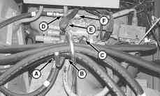
6.Removebatterycables(C)fromstartermotor.
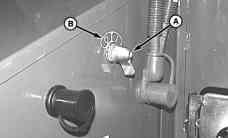
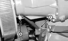
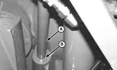
7.Removevariabledrivesheavesupportjamnut(A).
8.Loosenvariabledrivesheavesupportjamnut(F).
9.Removeretainingpin(G)andsupportrod(B).
10.Removecapscrews(D)andsheavesupportbracket (E).
NOTE:Capandplugalllinesandhoses.
11.Disconnect:
• Radiatorandheaterhoses
• Enginewiringharness
• Coldweatherstartaid
• Rotaryscreendrivebelt
• Fuelsupplyandreturnlines
• Engineoildrainhose
12.Remove:
• Mufflerassembly
• Bothchargeairtubes
NOTE:DONOTdisconnectrefrigerantlines.
• Alternator
• Airconditioningcompressor
• Upperandlowerfanshroud
• Coolingfan,spacer,washerandsheave
A—VariableDriveSheave SupportJamNut B—SupportRod C—BatteryCables(4used) D—CapScrew(2used)
E—SheaveSupportBracket F—VariableDriveSheave SupportJamNut G—RetainingPin
OUO6083,00004E61926MAY102/5
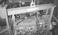
13.InstallliftingstrapsJD2441(A)andJD2442(B)on engine.
CAUTION:Usecarewhenliftingengine andNEVERpermitanypartofthebodytobe positionedunderaloadbeingliftedorsuspended.
CAUTION:Theapproximateweightofthe 6068engineis711kg(1568lb).
Specification
Engine—6.8L—Weight..................................................................711kg (1568lb.)
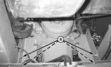
14.Removefrontenginemount(A)fromenginerail.
15.Removegearcasetoenginecapscrews(B).
16.Carefullymoveengineawayfromgearcase.Lift engineoutofcombine.
A—CapScrew(4used)B—CapScrew(4used)
OUO6083,00004E61926MAY104/5
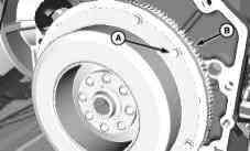
17.Removecapscrews(A)andseparateenginegear casecouplerfromflywheel(B).
18.Repairorreplaceasnecessary.
A—CapScrew(6used) B—Flywheel
OUO6083,00004E61926MAY105/5
InstallEngine—6.8L
1.Inspectbearing(A)inflywheel(B).Replaceasneeded (SeeRemoveAndInstallFlywheelPilotBearingin Section20,Group05.).
A—Bearing B—Flywheel
OUO6083,00004E71926MAY101/4
2.ApplyPM37477ThreadLockandSealer(Medium Strength)tocapscrews(A)andinstallenginegear casecouplertoflywheel(B).Tightentospecification.
Specification
EngineGearCase
CouplerCap Screws—6.8L Engine—Torque.............................................................................55N∙m (41lb.ft.)
A—CapScrew(6used) B—Flywheel
Continuedonnextpage
OUO6083,00004E71926MAY102/4
CAUTION:Usecarewhenliftingengine andNEVERpermitanypartofthebodytobe positionedunderaloadbeingliftedorsuspended.
CAUTION:Theapproximateweightofthe 6068engineis711kg(1568lb).
IMPORTANT:UseonlyaliftingslingliketheJDG23 whichhasaspreaderbar.Othertypesoflifting slingscoulddamagethecylinderhead.
3.Carefullylowerenginetoalignwithenginegearcase.
4.Install:
• Gearcasetoenginecapscrews;tightento specification
Specification
GearCasetoEngine
CapScrews—Torque..................................................................340N∙m (250lb.ft.)
• Frontenginemountcapscrews;tightento specification
Specification
FrontEngine
MounttoEngineRail
CapScrews—Torque..................................................................123N∙m (90lb.ft.)
5.Removeliftingsling(C)andliftingstraps(AandB).
6.Installvariabledrivesupportbracketusingcaps screws.Tightencapscrewstospecification.
Specification
VariableDrive
SupporttoEngineCap
Screws—Torque..........................................................................350N∙m (255lb.ft.)
7.Installvariabledrivesupportrodusingretainingpin.
8.Tightenvariabledrivesheavesupportjamnutto sheavesupportbracket.
9.Installjamnutontosupportrodandtightento specification.
Specification
VariableSheave SupportJam NuttoSheaveSupport Bracket—Torque..........................................................................250N∙m (185lb.ft.)
10.Installairconditioningcompressorandtightencap screwstospecification.
Specification
AirConditioning CompressorCap
Screws—Torque............................................................................35N∙m (26lb.ft.)
NOTE:Fabricatetwodowelpins,6mm(1/4in.)x180 mm(7in.)long,toaidinaligningthefanassembly.
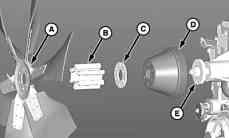
11.Installsheave(D),washer(C),spacer(B),andfan(A) ontohub(E)usingdowelpinstoaidinalignment.
12.Installfourcapscrewsfingertight;thenremovedowel pins.Installremainingcapscrews,andtightento specification.
Specification
FantoFanHubCap Screws—Torque............................................................................80N∙m (60lb.ft.)
13.Install:
• Twopiecefanshroud
• Upperandlowerradiatorhosesandsurgetank hose;tightentospecification
Specification
RadiatorHose Clamps—Torque............................................................................11N∙m (97lb.in.)
• Bothchargeairtubes:tightentospecification
Specification
ChargeAirCoolerTube Clamps—Torque............................................................................11N∙m (97lb.in.)
• Heaterhoses
• Alternator
• Fandriveandrotaryscreendrivebelts
• Exhausttubeandmufflerassembly
14.Connect:
• Enginewiringharness
• Coldweatherstartaid
• Fuelsupplyandreturnlines
• Engineoildrainhose
• Batterycablestostartermotor
15.Installenginecoversandshields.
16.Fill:
• Enginewithcorrectoil(SeeOperator’sManual)
IMPORTANT:FollowBleedAirFromCoolantSystem procedureinrelevantCTM.
• Coolingsystemwithcoolant
17.Openfuelsupplyvalveonbottomoftank.
18.Turnbatterydisconnectswitchto“I”onposition.
19.FollowenginebreakinprocedureinrelevantCTM.
OUO6083,00004E71926MAY104/4
A—Fan B—Spacer C—Washer
D—Sheave E—Hub
SetHydrostaticPumpDriveGearBacklash
NOTE:Donotusemorethanoneplasticshim.
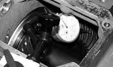
1.Selectshimstoprovidebacklash(dimensiononend ofsmallergearto+0.1to0.0mm(+0.004to0.0in.) attightestconditionofgearmesh.
2.InstallshimsandOringonpilotdiameterofbearing housing.Tightencapscrewstospecification.
Specification
HydrostaticPump DrivetoGearCase CapScrews—Torque...................................................................50N∙m (40lbft)
Shimsavailableare:
• 0.08mm(0.003in.)
DisassembleandAssembleOilScreen
NOTE:Whenevergears,shafts,orbearingshave beenreplaced,cleanoilscreen.
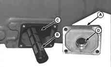
1.Removecover(A)withgasket.
2.Cleanoilscreen(B).
3.Thoroughlycleansumparea(C).
4.Installoilscreen.Besureclosedendofscreenfits inrecessonoppositeside.Pilot(D)mustbeDOWN topositionscreenlowinsump.Tightencoverbolts tospecification.
Specification
EngineGearCase OilScreenCoverCap Screws—Torque............................................................................25N∙m (216lbin.)
• 0.13mm(0.005in.)
• 0.25mm(0.010in.)
• 0.50mm(0.020in.)
AG,OUO6022,3801925JUL001/1
NarrowBodyOilScreenShown
A—Cover B—OilScreen C—Reservoir D—Pilot
RG53986,0000EE31908FEB101/1
DisassembleandAssembleOilTrough
NOTE:Removehose(E)fromfittingifequippedwith 5speedfeederhousegearcase.
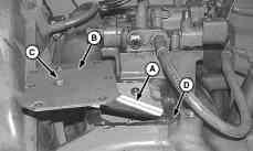
1.Removeoiltrough(A)withcover(B).
IMPORTANT:Correctlocknutsmustbeusedoncap screws(C).Standardnutsmaycomeloose, fallintogearcaseandcausedamage.
IMPORTANT:Becertaintroughisattachedtocoveras shownoroilwillnotbedeliveredtobearings.
2.Replaceifdamaged.
3.Applyathinbeadofsealantallaroundsurface(D).
4.Installoiltrough.Tightencapscrewstospecification.
Specification
OilTroughCoverCap
Screws—Torque......................................................................25±5N∙m (221±44lbin.)
A—OilTrough B—Surface C—CapScrew
D—Surface E—Hose
DisassembleandAssembleDipstickTube
NOTE:Removedipsticktubeonlyifdamaged.
1.Removedipsticktube(A).Tubeisatightfit.
2.Applyacoatofthreadlockandsealerinbore(B).
3.Driveintubeuntilitseats.
A—DipstickTube B—Bore
RG53986,0000EE41908FEB101/1
AG,OUO6022,2971905AUG051/1
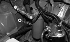
RemoveandInstallFilter
1.Turnfilter(A)counterclockwiseandremove.
2.Installfilter(A).
3.Fillgearcasetocapacity.(SeeOperator’sManual.)
4.Checkoillevelafterengagingdrives.
RG53986,0000D111925JAN101/1
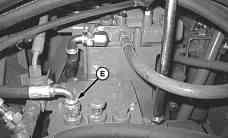
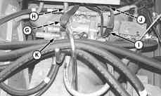
RemoveandInstallPressureRegulating Valve
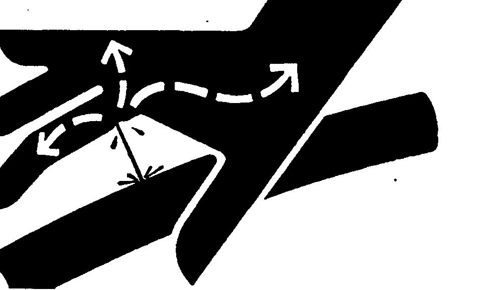
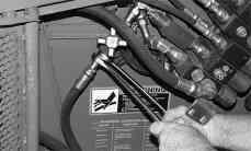
CAUTION:Escapingfluidunderpressurecan penetratetheskincausingseriousinjury. Avoidthehazardbyrelievingpressurebefore disconnectinghydraulicorotherlines.Tighten allconnectionsbeforeapplyingpressure.Search forleakswithapieceofcardboard.Protecthands andbodyfromhighpressurefluids.
Ifanaccidentoccurs,seeadoctorimmediately. Anyfluidinjectedintotheskinmustbe surgicallyremovedwithinafewhoursor gangrenemayresult.Doctorsunfamiliarwith thistypeofinjurymaycallDeere&Company MedicalDepartmentinMoline,Illinois,orother knowledgeablemedicalsource.
1.Fullylowerheaderandreeltogroundandcontinue todepressswitchfor5secondstorelievehydraulic systempressure.Shutoffengineandclose accumulator.Removekey.
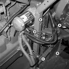
2.Disconnectlines(A—F).
3.Disconnectwiresleads(G—J).
4.Removecapscrews(K)andremovevalve.
5.Inspectforwearordamage.Replaceasnecessary.
NOTE:Donotusesealerongasket.
6.Installvalve.Tightencapscrewstospecification.
Specification
PressureRegulating
ValveCap
Screws—Torque............................................................................25N∙m
7.Connectwires(G—J).
8.Connectlines(A—F).
A—HydraulicHose
B—HydraulicHose
C—HydraulicHose
D—HydraulicHose
E—HydraulicHose
F—HydraulicHose
G—Connector
H—Connector
I—Connector
J—Connector
K—CapScrews(7used)
AG,OUO6022,2941925JUL001/1
Accumulator
Brakecharging
Prechargepressure........................................70303
Checkingheaderfloatsystem............................70302
Essentialorrecommendedtools........................70301
Fivespeedfeederhousedrivegearcase
Prechargepressure........................................70303
Generalinformation...........................................70301
headerfloatprechargepressure........................70303
Shutoffvalve
Removeandinstall.......................................701516
Twospeedautomatictransmission
Prechargepressure........................................70303
Accumulatorshutoffvalve
Removeandinstall..........................................701516
Actuator
Fanspeed
Adjust.........................................................1202022
Foldingauger
Removeandinstall.....................................1302013
Adhesivesandsealants.......................................101023
AHCpump
Install................................................................701011
Mark...................................................................70103
Remove..............................................................70102
Airconditioningsystem
Blowermotor
Removeandinstall.........................................90103
Charge.............................................................900522
Checkrefrigerantoilcharge.............................900522
Clutchhubclearance,check............................900513
Compressorclutch,disassembleand assemble........................................................900512
Compressorholdingfixture
DFRW20airconditioningsystem.................199051
Compressormanifold,inspect.........................900513
Compressoroilinformation..............................900521
Compressorreliefvalve,removeand install..............................................................900516
Compressor,disassemble,inspectand assemble........................................................900514
Compressor,removeandinstall........................90056
Correctoilcharge.............................................900521
Discharge/recoverrefrigerant............................90055
Evacuate..........................................................900520
Flush................................................................900518
Hoseandtubingconnectiontorques.................90055
Othermaterial....................................................90054
Purge...............................................................900519
Recirculatorfanmotordriver
Removeandinstall.........................................90103
Recirculatormotor
Removeandinstall.........................................90104
Serviceequipmentandtools..............................90053
Servicepartskits................................................90055
Specifications.....................................................90054
Systeminformation..........................................900517
Temperaturecontroldooractuator
Removeandinstall.........................................90104
Testshaftsealleakage....................................900511
Testvolumetricefficiency...................................90058 Airconditioningsystem(R134a)
Essentialorrecommendedtools........................90051 Airconditioningsystemwithprecleaner
Generalinformation...........................................90102
Airfilter
Restrictionswitch
Removeandinstall.......................................403521
Airintakesystem
Othermaterials..................................................30051
Specifications.....................................................30051 Turbochargerrepair...........................................30052
Airtemperaturesensors
Replace............................................................901012
Alternator
Pulley
Removeandinstall.........................................40453
Removeandinstall............................................40452
Specification.......................................................40451 Alternatorbelt
Removeandinstalll............................................40452
Alternatorrepair
Engineaccessories............................................40452
Armrestcontrolpivot
Removeandinstall..........................................901537 Armrestdisplayunit
Removeandinstall..........................................403016 Auger
Cleangrainloading
Removeandinstall.....................................1302519
Foldingaugerrings
Removeandinstall...................1302014,1302015
Foldinghorizontalauger
Explodedview............................................1302011
Foldinghorizontalaugerpivot
Explodedview............................................1302012
Fronthorizontalunloading
Install..........................................................1302018
Remove....................................1302016,1302017
Horizontalunloading
Elbow
Install......................................................1302029
Remove..................................................1302027
Gearcase
Install......................................................1302024
Remove..................................................1302020
Highunloadrate...........................................130204
Install............................................................130207
Regularunloadrate......................................130203
Remove........................................................130206
Tube
Install......................................................1302025
Remove..................................................1302024
Continuedonnextpage
Outerfoldingaugerassembly
Removeandinstall.....................................1302013
Rearhorizontalfolding
Install..........................................................1302019
Remove......................................................1302015
Augerdrivecountershaft
Install................................................................130102
Remove............................................................130102
Axlebearingsandseals
Removeandinstall..........................................503539
Axleextensiontubes
Install..................................................................50409
B
Backupalarm
9570,9670,9770.............................................403536
9870.................................................................403535
Switch
Removeandinstall.......................................403534
Backlightingdriver
Removeandinstall..........................................403018
Basicelectricalcomponenthandling
Safety.................................................101032,10156
Batteries
Charging............................................................40056
Connectingboosterbatteries.............................40055
Connectingcables.............................................40057
Electricalsystemsafety.....................................40052
Electrolytespecificgravity
Check.............................................................40053
Preventbatteryexplosions.................................40051
Removeandinstall............................................40054
Battery
Replacement......................................................40054
Bearing
Primarycountershaft
Removeandinstall.......................................120109
Rotor
Removeandinstall.....................................1200525
Bearings
Hydrostaticgearset,preload.........................1400546
Belt
Unloadingaugerdrive
Removeandinstall.......................................130101
Beltreplacement
Cleangrainelevator
Remove........................................................130253
Cleangrainelvator
Install............................................................130259
Belts
Adjusting
Feederhousevariablespeed.....................1101565
Bladeinserts
Cleaningfan
Removeandinstall.....................................1202027
Blowermotor
Removeandinstall............................................90103
Boltandscrewtorquevalues
Metric...............................................................101021
Unifiedinch......................................................101022
Brakeassemblies
Tworangeautomatictransmission
Assemble......................................................501535
Disassemble.................................................501530
Install............................................................501541
Remove........................................................501528
Brakedisks
Tworangeautomatictransmission
Checkthickness...........................................601510
Repair...........................................................601511
Brakefluid............................................................102011
Brakefluidreservoir.............................................601011
Brakemodule
Shrinkringinstallationtool
DFHXT5.......................................................199055
Brakepedals,disassembleandassemble
Tworangeautomatictransmission....................60154
Brakes
Assemble...........................................................60108
Bleeding(doublebleedscrew)........................601012
Brakepedals,assemble...................................601016
Brakepedals,disassemble..............................601016
Deglazinglinings................................................60103
Druminstallation................................................60108
Drumremoval....................................................60103
Fluidreservoir..................................................601011
Mastercylinderinstallation.................................60109
Mastercylinderremoval.....................................60109
Mastercylinder,assemble...............................601010
Mastercylinder,disassemble...........................601010
Othermaterial....................................................60101
Parkingpedal,assemble..................................601022
Parkingpedal,disassemble.............................601022
Removebrakeshoe...........................................60104
Repair................................................................60105
Serviceequipmentandtools..............................60101
Slavecylinder,assemble.................................601015
Slavecylinder,disassemble.............................601015
Slavecylinder,install........................................601014
Slavecylinder,remove.....................................601014
Specifications.....................................................60102
Breakinengineoil.................................................10207
Bulb
Cleaningshoelight
Replace..........................................................40256
Frontturnsignal
Taillight
Replacement...............................................40256
Hazard/warninglight
Replace..........................................................40256
Maximumtiltindicator
Replace..........................................................40257
Sidelight
Replacement..................................................40256
Turnsignal
Replace..........................................................40257
Continuedonnextpage
Bulbs
Safetyruleswhenreplacing
Highintensitydischarge(Xenon)...................40251
Bulkhead
Conveyorauger
Removeandinstall.....................................1202011
Rotordrive Alignment.................................................12005102
Cab Install................................................................901522
Operator'sseat
Removeandinstall.......................................901533
Remove..............................................90156,901514
Cabdoor
Disassembleandassemble.............................901548
Latchstriker
Removeandinstall.......................................901549
Removeandinstall..........................................901546
Cabinnerroof
Removeandinstall..........................................901529
Cabpowermodule(CPM)
Removeandinstall............................................40203
Cabroof
Removeandinstall..........................................901528
Camandpistoncarrier
Removeandinstall..........................................503530
Camlobemotor
Controlvalve,disassembleand assemble........................................................503512
Controlvalve,removeandinstall.......................50358
Install..................................................................50358
Othermaterials..................................................50355
Remove..............................................................50357
Serviceequipmentandtools..............................50354
Specifications.....................................................50356
Stackvalveseals
Removeandinstall.......................................503535
Camposition
Sensor
Removeandinstall 13.5L........................................................403525
Careandmaintenanceofbelts
Tuneupandadjustment....................................10152
Carrierbearing
Primarydriveshaft
Replace......................................................1201022
Chaffer
Chafferframe
Removeandinstall
Chafferframe(withselfleveling shoe).....................................................1202056
ChafferFrame
Removeandinstall
Chafferframe(withoutselfleveling shoe).....................................................1202054
Openinggaugecalibration.............................1202030
Page
Withremoteshoe.......................................1202034
Removeandinstall......................1202030,1202034
Chaffer/sieveframeclevis(selfleveling shoe).........................................................1202029
Chain
Cleangrainelevator
Adjustment...................................................130251
Chargeaircooler
Clean..................................................................30055
Removeandinstall............................................30053
Chargehousing
Unloadingauger
Install..........................................................1302033
Remove......................................................1302031
Chargepump
Removeandinstall..........................................501071
Repair..............................................................501073
Chopper
Bladereplacementandconfiguration
9570STS...................................................1201512
9670,9770and9870STS.........................1201514
Rotorbearing(lefthand)
Replace......................................................1201521
Rotorbearing(righthand) Replace......................................................1201523
Chopperraise/loweractuator
Removeandinstall..........................................120158
Cleangrainauger,lower Removeandinstall........................................1302520
Cleangrainelevator Chain
Cleangrainelevatorbeltreplacement
Cleangrainloadingauger
Cleangrainpaddle
Cleangrainpaddlechain
Cleaningfan Actuator Adjust.........................................................1202022
Continuedonnextpage
Remove......................................................1202017
Drivejackshaft
Disassembleandassemble.......................1202019
Removeandinstall........................................1202023
Speedcontrol.................................................1202016
Cleaningfanbearing
Removeandinstall........................................1202012
Cleaningfansheave
Removeandinstall........................................1202012
ClimaTrak
Switch
Airconditioningcontrol
Removeandinstall.....................................40306
Heatercontrol
Removeandinstall.....................................40306
Clutch
Electromagnetic
Header
Explodedview...........................................120353
Header
Removeandinstall.......................................120351
Clutch,slip
Conveyorauger
Removeandinstall.....................................1202010
Coldweatherstartingaid
Removeandinstall............................................30107
Replacecan.......................................................30107
CommandTouchconsole
Consolecontrols..............................................403014
Multifunctionhandle
Removeandinstall.......................................403024
Removeandinstall..........................................403015
Switches
Activeheadercontrol
Removeandinstall...................................403019
DialASpeed
Removeandinstall...................................403019
Compositestylepanels
Repair................................................................80053
Pulledoutstud................................................80053
Ribscracked...................................................80053
Compressorholdingfixture
DFRW20airconditioningsystem.....................199051
Concave
Adjustingmotor
Removeandinstall.....................................1200584
Adjustingtube
Removeandinstall.....................................1200584
Level
Adjust.........................................................1200579
Removeandinstall........................................1200572
Concavepositionsensor
Removeandinstall............................................40359
Condenser
Install..................................................................90107
Remove..............................................................90105
Repair................................................................90107
Connectorrepair
RArepairprocedure.........................................40108
RAErepairprocedure.....................................401039
RAFrepairprocedure.....................................401041
RAGrepairprocedure.....................................401044
RAHrepairprocedure.....................................401046
RAIrepairprocedure......................................401047
RAJrepairprocedure......................................401048
RAKrepairprocedure.....................................401051
RALrepairprocedure.....................................401053
RBrepairprocedure.......................................401012
RCrepairprocedure.......................................401014
RDrepairprocedure.......................................401017
RErepairprocedure.......................................401019
RFrepairprocedure........................................401021
RGrepairprocedure.......................................401024
RIrepairprocedure.........................................401025
RJrepairprocedure........................................401027
RKrepairprocedure.......................................401032
RMrepairprocedure.......................................401034
RNrepairprocedure.......................................401036
Connectors
HandlingandRepair..........................................40107
Console
CommandTouch
Removeandinstall.......................................403015
Consoleswitchpanel
Removeandinstall..........................................403020
Controlcable
Hydrostaticpump.............................................501074 Adjust...........................................................501075
ControlUnits
Programming.....................................................10157
Controlsandinstruments
Identification.......................................................40302
Conveyor Chain
Adjust...........................................................110053
Measurechainwear.....................................110056
Removeandinstall.......................................110054
Chainlink
Remove........................................................110056
Drivechaintightenerandguides
Disassembleandassemble.......................1101564
Drum
Adjustheight...............................................1100510
Removeandinstall....................1100511,1100513
Wearstrips
Replace........................................................110058
Conveyorauger
Bulkhead
Removeandinstall.....................................1202011
Driveshaft
Removeandinstall.......................................120204
Removeandinstall..........................................120207
Slipclutch
Removeandinstall.....................................1202010
Trough
Removeandinstall.......................................120208
Othermaterial....................................................40105 Page
Continuedonnextpage
Conveyorchain
Adjusting..........................................................110054
Conveyorchainslat
Feederhouse
Remove........................................................110057
Coolant
Additionalinformation........................................10206
Dieselengine.....................................................10204
Supplementaladditives......................................10205
Testing................................................................10207
Warmtemperatureclimates...............................10205
Coolanttemperature
Sensor
Removeandinstall.......................................403518
Coolingsystem
Installradiator
9.0L.............................................................201018
Removeradiator
13.5L...........................................................201016
6.8L.............................................201010,201013
9.0L.............................................................201016
Replacethermostats........................................201021
Rotaryscreen
Removeandinstall.........................................20108
Rotaryscreendrive............................................20104
Rotaryscreenknifecomb
Adjust...........................................................201010
Specifications.....................................................20102
Testradiator.....................................................201020
Testradiatorcap..............................................201021
Waterpump
Repairorreplace..........................................201021
Cornerpost
Removedigitaltachometermodule.................403013
Removeheadercontrolmodule.......................403013
RemoveVisionTrakmodule.............................403013
Cornerpostmaincircuitboard
Replace..............................................................40309
Countershaft
Tworangeautomatictransmission
Explodedview..............................................501591
Install............................................................501592
Remove........................................................501587
Repair...........................................................501589
Cover
Separatortop
Removeandinstall.....................................1200513
Cropdiverter
Removeandinstall........................................1201518
Crossaugercountershafthub
Install................................................................130102
Remove............................................................130102
Crossaugercountershaftshearbolt
Install................................................................130102
Remove............................................................130102
Crossaugers
Install..............................................130054,1300510
Remove............................................130051,130057
Cylinder
Headerlift
Disassembleandassemble.....70203, 70204
Steeringcylinder
Disassembleandassemble...........................70209
Unloadingaugerdrive
Removeandinstall.........................................70208
Unloadingaugerswing
Adjust.............................................................70207
Removeandinstall.........................................70205
Unloadingaugerswingcylinder
Explodedview................................................70206
Cylinder,master
Adjust...............................................................601011
Defectivebelts
Tuneupandadjustment....................................10153 Dieselfuel................................................10201,10202 Dieselfuelsystem
Fueltankshutoffvalve
Removeandinstall 9870............................................................30105
Fueltankshutoffvalveanddrainvalve
Removeandinstall
9570,9670,9770........................................30103
Removeandinstallfueltank..............................30101
Dieselfuelsystems
Othermaterials..................................................30101
Specifications.....................................................30101
Differentialmodule
Tworangeautomatictransmission
Assemble......................................................501552 Disassemble.................................................501546 Explodedview..............................................501550 Install............................................................501558 Remove........................................................501543
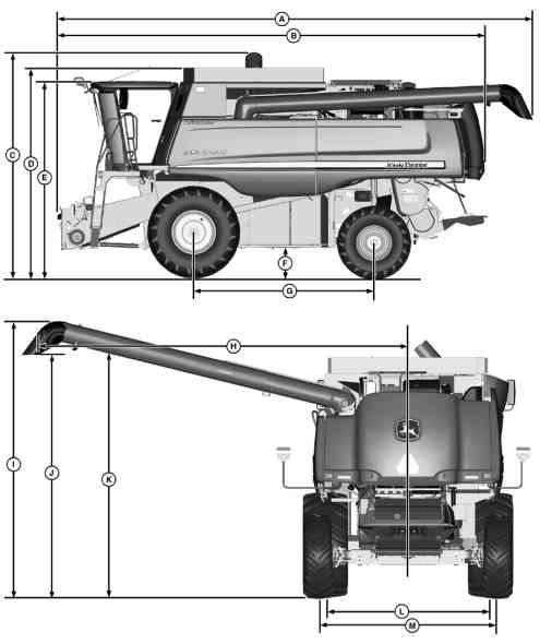
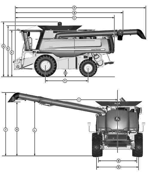
Dimensions
9570STScombine............................................10105
9670STS,9770STS.......................................101013
9870STScombine..........................................101019
Referencepoints
9570STScombine.........................................10106
9670STS,9770STS...................................101014
9870STScombine.......................................101020
Dipsticktube
Disassembleandassemble...........................1400560
Dischargebeater
Dischargebeatergrateframe
Removeandinstall.....................................1200557
Removeandinstall........................................1200561
Wings Removeandinstall.....................................1200561
Dischargebeaterdrivehub
Removeandinstall........................................1200568
Continuedonnextpage
Dischargebeatergrate
Gratesection
Removeandinstall.....................................1200553
Dischargebeaterhousing
Removeandinstall........................................1200568
Displacementcontrolvalve
Removeandinstall..........................................503527
Displayunit
Armrest
Removeandinstall.......................................403016
Domelight
Replace..............................................................40257
Drainoil
Tworangeautomatictransmission..................501514
Drivecylinder
Unloadingauger
Removeandinstall.........................................70208
Drivepump
Disassemble....................................................501039
Reel/belt
Removeandinstall.......................................701015
Drivepump,assemble.........................................501051
Driveshaft
Carrierbearing
Replace......................................................1201022
Primarycountershaftgearcase.....................1201022
Removeandinstall
StyleA....................................................1201015
StyleB....................................................1201018
Removeandinstall
StyleA........................................................1201015
StyleB........................................................1201018
Drivewheel
Bolttorque
Dualwheel......................................................50408
Singlewheel...................................................50407
Drives
Poweredrearwheelassist
Flushing..........................................................50357
Strawchopper
Jackshaft,remove
StyleA....................................................1201524
Dualwheels
Install................................................................504012
Dualwheelsandtrussrod
Install................................................................504012
Elbow
Horizontalunloadingauger
Install..........................................................1302029
Remove......................................................1302027
Unloadingauger
Removeandinstall.....................................1302026
Electrical
Batteries
Preventdamagetoelectrical systems........................................................40052
Safety.............................................................40051
Componenthandlingprecautions......................40106
Visualinspection................................................40106
Electricalsystem
Batteries
Changingbatteries.........................................40056
Operatorsstation
CommandTouchconsoleswitchpanel
Removeandinstall...................................403020
Cornerpostmaincircuitboard
Replace.......................................................40309
Headerandseparatorengageswitch
Removeandinstall...................................403017
Neutralsafetyswitch
Replace.....................................................403022
Sensorsandswitches
GreenStarmassflowsensor
Removeandinstall.....................................40552
Groundspeed
Removeandinstall.....................................40354
Lateraltiltcontrolsensor
Removeandinstall...................................403510
Positionreceiver
Disassembleandassemble......................405525
Removeandinstall...................................405526
Wiper
Windshieldwiper
Adjust..........................................................40404
Wipermotor
Removeandinstall.....................................40401
Electrolytespecificgravity
Checking............................................................40053
Electromagneticclutch
Header
Explodedview..............................................120353
Electronicdisplacementcontrolvalve
Neutraladjustment...........................................501069
Elevator
Cleangrain
Install............................................................130259
Remove........................................................130253
Tailings
Install..........................................................1202519
Remove......................................................1202512
Engine
Flywheel...........................................................200521
Gearcase
Removeandinstall.......................................140058
Install
13.5L...........................................................200519 6.8L...............................................................20056
9.0L.............................................................200512
Remove 13.5L...........................................................200515 9.0L.................................................20053,20059
Repair...................................20053,20103,30052
Enginegearcase
Chopper/unloadingsystemdrive
Disassembleandassemble.......................1400548
Continuedonnextpage
Dipsticktube
Disassembleandassemble.......................1400560
Generalinformatiion.........................................140057
Hydrostaticgearset
Disassembleandassemble.......................1400544
Preloadbearings........................................1400546
Setgearposition........................................1400545
Hydrostaticpumpdrive
Disassembleandassemble.......................1400557
Preloadbearings........................................1400558
Hydrostaticpumpdrivegear
Setbacklash...............................................1400559
Oilfilter
Removeandinstall.....................................1400561
Oilscreen
Disassembleandassemble.......................1400559
Oiltrough
Disassembleandassemble.......................1400560
Pressureregulatingvalve
Disassembleandassemble.......................1400564
Removeandinstall.....................................1400562
Removeandinstall..........................................140058
Separatordrive
Disassembleandassemble.......................1400553
Preloadbearings........................................1400555
Setgearbacklash.......................................1400556
Separatordrivewetclutch
Disassembleandassemble.......................1400534
Separatorgear
Preloadbearings........................................1400552
Setseparatorgearposition............................1400551
Specifications.................................................1400515
Transfergearcase
Disassembleandassemble.......................1400530
Enginegearcaseandvalve
Essentialorrecommendedtools......................140051
Othermaterial..................................................140054
Specifications...................................................140055
Engineoil
BreakIn.............................................................10207
Engineoilpressure
Sensor
Removeandinstall.......................................403524
Enginespeedsensor
Sensor
Removeandinstall.......................................403526
Essentialorrecommendedtools
Accumulator.......................................................70301
Airconditiongsystemcomponents....................90101
Airconditioningsystem(R134a)........................90051
Coolingsystem..................................................20101
Enginegearcaseandvalve.............................140051
Feederhousedrivesandreversergear case................................................................110151
Finaldrives.........................................................50301
Fivespeedfeederhousedrivegear case................................................................110301
Harnessandconnectorrepair......40101, 40451,40501
Horizontalunloadingaugerandgear case................................................................130201
Hydraulicpump..................................................70101
Hydraulicreservoir.............................................70051
Hydraulicvalves.................................................70151
Hydrostaticsystem.............................................50101
Primarycountershaftgearcase.......................120301
SensorsandSwitches.......................................40351
Separatordrives...............................................120101
Separatorrepair...............................................120051
Singlereductionfinaldrive.................................50351
Steering..............................................................60051
Tiresandwheels................................................50401
Topshaftandslipclutch...................................110101
Tworangeautomatictransmission....................50151
Verticalunloadingaugerandlowergear case................................................................130151
Evaporator
Replace..............................................................90109
Evaporatortemperaturesensor
Removeandinstall..........................................901010
Exhaustgasrecirculation
Sensors
Removeandinstall.......................................403527
Exhaustgasrecirculation(EGR)mixedgas temperaturesensor
Sensor
Removeandinstall.......................................403528
Expansionvalve
Replace............................................................901010
Feedaccelerator
Shaft
Remove........................................................120057
Wearstrips
Removeandinstall.....................................1200512 Feedflights
Removeandinstall........................................1200598
Feederhouse
Adjustvariablespeedbelt..............................1101565
Adjusting
Conveyorchain............................................110054 Belt
Fixedspeed
Replace...................................................1101572
Variablespeed
Replace...................................................1101569
Conveyorchain
Adjust...........................................................110053
Measurewear...............................................110056
Removeandinstall.......................................110054
Conveyorchainlink
Remove........................................................110056
Conveyorchainslat
Remove........................................................110057
Conveyordrum
Removeandinstall....................1100511,1100513
Continuedonnextpage
Conveyorwearstrips
Replace........................................................110058
Countershaft
Fixedspeed
Disassembleandassemble....................1101521
Drive
Fivespeedcontrolvalve
Disassembleandassemble........................70157
Drum
Adjust.........................................................1100510
Feedplatesupport
ExplodedView............................................1100524
Fixeddrivesheave
Removeandinstall.....................................1101535
Fixedspeed
Drivetightener
Disassembleandassemble....................1101562
Lowershaft
Removeandinstall.....................................1101560
Midfloorassembly
Removeandinstall...................1100519,1100520
Multicoupler
Disassembleandassemble.........................701516
Inspect..........................................................701516
Mutlispeeddrivebelt
Removeandinstall.....................................1101571
Oilcooler
Removeandinstall.....................................1101537
Othermaterial
Drivesandreversergearcase.....................110152
Tiltframe......................................................110251
Removeandinstall..........................................110052
Reversergearcase........................................1101538
Disassembleandassemble.......................1101539
Oilpump
Disassembleandassemble....................1101553
Removeandinstall.....................................1101536
Reversershiftpiston
Removeandinstall.....................................1101557
Rightforwardvalveblock
Removeandinstall.........................................70155
Singlepointlatching
Levelland
ExplodedView........................................1100520
Specifications
Topshaftandslipclutch...............................110102
Subfloorassembly
Removeandinstall.....................................1100517
Topshaft
Disassembleandassemble........................1101011
Topshaftslipclutch
Disassembleandassemble.........................110103
Install............................................................110106
Remove........................................................110102
Topshaftsupports
Removeandinstall.......................................110107
Variabledrivecountershaft
Disassembleandassemble.......................1101515
Variabledrivesheaves
Cams
Removeandinstall...............1101522,1101533
Repair.....................................................1101526
Feederhousedrivegearcase
Fivespeed
Crosssectional...........................................1103010
Disassemble...............................................1103013
Install............................................................110306
Ouputshaft
Crosssectional.......................................1103012
Feederhousedrivesandreversergearcase
Essentialorrecommendedtools......................110151
Specifications...................................................110153
Feederhouserepair
Conveyor
Conveyorchainslat
Removing..................................................110057
Drumheight
Adjust......................................................1100510
Feederhousedrivesandreversergear case
Conveyordrivechain,tightenerand guides
Disassembleandassemble....................1101564
Fixeddrivesheave
Removeandinstall.................................1101535
Reversergearcase
Removeandinstall.................................1101536
Reversergearcaseoilpump
Disassembleandassemble....................1101553
Variabledrivesheavesandcams
Removeandinstall...............1101522,1101533
Lateraltiltframeandbeam..............................110252
Feederhousereversergearcase
Lubricants........................................................102011
Feederhouse/conveyor
Othermaterial..................................................110051
Specifications...................................................110051
Finaldrive
Assemble...........................................................50308
Disassemble......................................................50308
Removeandinstall............................................50304
Singlereduction
Adjustspindlebearing(alternate method)......................................................503018
Adjustspindlebearing(preferred method)......................................................503017
Finaldrives
Specifications.....................................................50303
Fivespeed
Controlvalve
Disassembleandassemble...........................70157
Fivespeedfeederhousedrivegearcase
Assemble.......................................................1103021
Crosssectional..............................................1103010
Disassemble..................................................1103013
Essentialorrecommendedtools......................110301
Continuedonnextpage
Gear/clutchassemblties
Disassembleandassemble.......................1103018
Outputshaft
Crosssectionalview..................................1103012
Remove............................................................110306
Fivespeedfeederhousegearcase
Othermaterial..................................................110305
Specifications...................................................110305
Flushing
Reel/beltpickupdrivesystem............................70055
Foldingauger Actuator
Removeandinstall.....................................1302013
Foldingaugerrings
Removeandinstall......................1302014,1302015
Foldinghorizontalauger
Auger
Explodedview............................................1302011
Housing
Explodedview..............................................130209
Pivot Explodedview............................................1302012
Foldingunloadingaugerpositionsensor
Removeandinstall..........................................403511
Foreaftframe
Install..............................................................1102514
Foreaftturnbuckles
Adjust..............................................................1102511
Freshairtemperature Sensors
Removeandinstall.......................................403527
Frontbulkhead
Removeandinstall........................................1200588
Frontchafferelement
Elementremoveandinstall............................1202050
Fronthorizontalunloadingauger
Install..............................................................1302018
Remove........................................1302016,1302017
Fuel
Diesel...................................................10201,10202
Handlingandstoring..........................................10201
Lubricity..............................................................10203
Fuelpressure,highandlow
Sensor
Removeandinstall.......................................403522
Fuelpressure,transferpump Sensor
Removeandinstall.......................................403522
Fuelrailpressure Sensor
Removeandinstall 6.8Land9.0Lengines............................403530
Fuelsender
Removeandinstall..........................................403521
Fueltank
Installstrainerandbreather...............................30106
Removeandinstall............................................30101
Sender
Removeandinstall.......................................403521
Fueltankshutoffvalve
Removeandinstall 9870...............................................................30105
Fueltankshutoffvalveanddrainvalve
Removeandinstall
9570,9670,9770...........................................30103
Fueltankstrainerandbreather
Removeandinstall............................................30106
Fueltemperature Sensor
Removeandinstall.......................................403529
Fuelsandlubricants
Transmissionandfinaldrive............................102010
Fullgraintank Sensor
Removeandinstall.........................................40356
Fuseidentification
Panel..................................................................40201
Gearcase
Cleangrainelevator.......................................1302515
Removeandinstall.....................................1302513
Horizontalunloadingauger
Disassembleandassemble.......................1302021 Install..........................................................1302024 Remove......................................................1302020
Primarycountershaft
Disassembleandassemble.........................120304
Gearshiftplanetarydrive
Tworangeautomatictransmission
Tworangeautomatictransmission
Oilrecommendations.....................................10209
Gearshiftleverandlinkage
Removeandinstall..........................................500524
Gearshiftlinkage Adjust...............................................................500525
Generalrepairprocedures
Fivespeedgearcase.......................................110306
Grainsaverdoor
Unloadingauger
Removeandinstall.......................................130205
Graintank
Crossaugers,install......................130054,1300510
Crossaugers,remove......................130051,130057 Explodedview
Continuedonnextpage
Extensions
9560STSand9650STS.............................130304
Highunloadrate...........................................130304
Regularunloadrate......................................130304
Grates
Separator,removeandinstall........................1200571
Grease
Extremepressureandmultipurpose................102011
GreenStar
Massflowsensor
Removeandinstall.........................................40552
Moisturesensor
Actuator
Removeandinstall.....................................40557
Circuitboard
Removeandinstall...................................405510
Disassembleandassemble...........................40556
Lowercellassembly
Removeandreplace.................................405511
Removeandinstall.........................................40554
GreenStarcomponents
Othermaterial....................................................40551
Specifications.....................................................40551
Groundspeed(fastidle)
Twospeedfourwheeldrive
Specification...................................................10101
Groundspeedsensor
Removeandinstall............................................40354
Gullwingdoors
Align...................................................................80055
Othermaterial....................................................80051
Removeandinstall............................................80051
Specifications.....................................................80051
Halogenbulbs
Safetyrules........................................................40251
Handlingbatteriessafely
Safety...................................................10052,40051
Hardwaretorquevalues
Metric...............................................................101021
Unifiedinch......................................................101022
Harness
Replace..............................................................40151
Header Electromagneticclutch
Explodedview..............................................120353
Install............................................................120353
Removal.......................................................120351
Headerandseparatorswitches
Removeandinstall..........................................403017
Headerelectromagneticclutch
Install................................................................120353
Removal...........................................................120351
Headerheightcontrolvalve
Removeandinstall..........................................701515
Headerheightsensor
Removeandinstall..........................................403510
HeaderLiftCylinder
Removeandinstall............................................70202
Headermagneticclutch
Specifications...................................................120351
Headliner
Removeandinstall..........................................901532
Heatercore
Removeandinstall............................................90105
HIDXenonballasts
Removeandinstall............................................40255
HIDXenonlighting
Removeandinstallballast.................................40253
Removeandinstalllight.....................................40253
Highpressureswitch
Replace............................................................901011
Highunloadrate
Horizontalunloadauger...................................130204
Horizontalunloadingauger
Elbow
Install..........................................................1302029
Remove......................................................1302027
Gearcase
Disassembleandassemble.......................1302021
Install..........................................................1302024
Remove......................................................1302020
Inspect.............................................................130202
Install................................................................130207
Remove............................................................130206
Tube Install..........................................................1302025
Remove......................................................1302024
Horizontalunloadingaugerandgearcase
Essentialorrecommendedtools......................130201
Othermaterial..................................................130201
Horn Switch
Removeandinstall.......................................403027
Housing Foldinghorizontalauger
Explodedview..............................................130209
Hub
Crossaugercountershaft
Install............................................................130102
Remove........................................................130102
Hydrauliccylinder
Headerlift
Disassembleandreassemble..70203, 70204
Removeandinstall.........................................70202
Hydrauliccylinders
Specifications.....................................................70201
Hydraulicpump
Assemble...........................................70109,701010
Disassemble......................................................70104
Essentialorrecommendedtools........................70101
Install................................................................701011
Main
Remove..........................................................70102
Mark...................................................................70103
Continuedonnextpage
Othermaterial....................................................70101
Reel/belt
Strawspreader
Explodedview...........................................701014
Seal
Replace..........................................................70105
Serviceequipmentandtools..............................70101
Specifications.....................................................70102
Hydraulicrepair
Hydraulicreservoir
Hydraulicsystem
Flushing......................................................70055
Reel/beltpickupandstrawspreader pump
Assemble..................................................701025
Reel/beltpickupdrivesystem
Flushing......................................................70055
Hydraulicreservoir
Essentialorrecommendedtools........................70051
Removeandinstall............................................70052
Specifications.....................................................70051
Temperaturesensor
Removeandinstall.......................................403518
Hydraulicsystem
Essentialorrecommendedtools........................50101
Flush..................................................................70055
Serviceequipmentandtools..............................50101
Specifications.....................................................50103
Hydraulicvalvestack
Disassambleandassemble.............................701513
Removeandinstall..........................................701511
Hydraulicvalves
Essentialorrecommendedtools........................70151
Othermaterial....................................................70151
Serviceequipmentandtools..............................70151
Hydrochargepressure
Switch
Removeandinstall.......................................403523
Hydrostaticdrivemotor
Controlbodyseals,replace...............................50255
Coverplateseal,replace...................................50254
Essentialorrecommendedtools........................50251
Generalview......................................................50253
Inspectionnotes...............................................502516
Portplate,assemble........................................502511
Portplate,disassemble......................................50257
Removeandinstall............................................50252
Rotarygroup,adjust.........................................502523
Rotarygroup,assemble...................................502518
Rotarygroup,disassemble..............................502513
Specifications.....................................................50251
Hydrostaticdrivepump
Assemble.........................................................502028
Boostpressurevalveseals,replace................502013
Boostpumpseal,replace..................................50208
Cleanpump........................................................50202
Controlpistoncoverseals,replace..................502010
Controlpiston,disassemble.............................502023
Cylinderassembly,disassemble......................502022
Disassemble....................................................502018
Driveshaftseal,replace....................................50205
Generalview......................................................50201
Inspectionnotes...............................................502025
Pressurecutoffvalveseals,replace...............502014
Removeandinstall............................................50203
Rotarygroup,install.........................................502032
Serialnumberplate............................................50202
Specifications.....................................................50201
Swashplateholdingtool
DFHXT3.......................................................199053
Zeroposition,adjust.........................................502036
Hydrostaticgearset
Disassembleandassemble...........................1400544
Preloadbearings............................................1400546
Setgearpositiion...........................................1400545
Hydrostaticmotor
Assemble.........................................................501028
Bearingplate
Inspect..........................................................501019
Cylinderblock
Inspect..........................................................501019
Cylinderblockspring
Replace........................................................501027
Disassemble......................................................50108 Driveshaft
Inspect..........................................................501027
Fixedswashplate
Inspect..........................................................501016
Inspect.............................................................501014 Inspectbearingandrace.................................501026 Inspectservopiston.........................................501026
Motorvalveblock(manifold)
Removeandinstall.......................................501036
Hydrostaticmotorandpump
Hydrostaticpump
Displacementvalvewithfeedrate
Explodedview..............................................501068
Electronicdisplacementcontrolvalve Neutraladjustment.......................................501069
Controlunit,removeandinstall.......................502015 Page
Continuedonnextpage
Endcover
Diassembleandassemble...........................501065
Orings
Replace........................................................501064
Removeandinstall..........................................501038
Hydrostaticpumpdrive
Disassembleandassemble...........................1400557
Hydrostaticpumpdrivebearings
Preload...........................................................1400558
Hydrostaticpumpdrivegear
Setbacklash..................................................1400559
Hydrostaticsystem
Abrasivecontamination....................................501014
Cavitation.........................................................501015
Controlcable
Adjust...........................................................501075
Removeandinstall.......................................501074
Flushing.............................................................50106
Hydrostaticmotor
Disassemble...................................................50108
Fixedswashplate
Inspect......................................................501016
Inspectparts.................................................501014
Removeandinstall.........................................50107
Thrustplate
Inspect......................................................501015
Hydrostaticmotorandpump
Lackoflubrication........................................501014
Motorandpump
Clean..............................................................50106
Overspeeding..................................................501015
Serialnumberplate............................................50106
Specifications.....................................................50104
Startupprocedure...........................................501076
Hydrostaticsystemrepair
Startupprocedure.............................................70056
Inserts
ThreadedRIVNUT
Removeandreplace..................................1200596
Instrumentsandcontrols
Identification.......................................................40302
Intakemanifoldpressuresensor
Sensor
Removeandinstall.......................................403528
Lateraltiltbeam
Removeandinstall..........................................110255
Lateraltiltcylinder
Explodedview..................................................110202
Fittings.............................................................110201
Hoses...............................................................110201
Removeandinstall..........................................110203
Lateraltiltframe
Removeandinstall..........................................110253
Lateraltiltsensor
Removeandinstall..........................................403510
Leaktestingairconditioningsystem
Withdye...........................................................900510
Leftfrontvalveblock
Removeandinstall............................................70153
Leftfrontvavleblock
Disassembleandassemble...............................70154
Leftpowermodule
Removeandinstall............................................40203
Light
Accessdoorworklight,bulb
Replace..........................................................40255
Auxiliaryfieldworklight,bulb
Replace..........................................................40255
Cleaningshoe
Replace..........................................................40256
Dome
Replace..........................................................40257
Frontturnsignal
Tail
Replacement...............................................40256
Hazard/warning,bulb
Replace..........................................................40256
Sidefinder(optional)lightbulb
replacement.....................................................40255
Sidelight
Replacement..................................................40256
Lightpaneldimmer
Switch
Removeandinstall.........................................40304
Light,(InfraRed)
Cabheadlightbulbreplacementand adjustment........................................................40252
Lights
Backlightingdriver
Removeandinstall.......................................403018
Lowpressureswitch
Replace............................................................901011
Lowshaftspeedsensor
Removeandinstall............................................40355
Lowercellassembly
GreenStarmoisturesensor
Removeandreplace....................................405511
Lowergearcase
Verticalauger
Removeandinstall.....................................1201518
Install..........................................................1301513
Continuedonnextpage
Remove........................................................130152
Lowershaft
Feederhouse
Removeandinstall.....................................1101560
Lubricant
Mixing...............................................................102012
Storage............................................................102012
Lubricityofdieselfuel............................................10203 M
Mainhydraulicpump
Install................................................................701011
Remove..............................................................70102
Mastercylinder
Adjust...............................................................601011
Disassembleandassemble.............................601010
Removeandinstall............................................60109
Mechanicaldisplacementcontrolvalve
Neutral,adjust..................................................501075
Metricboltandscrewtorquevalues....................101021
MetricORingTorqueChart
TorqueChartORingMetric.............................101025
Midfloorassembly
Removeandinstall......................1100519,1100520
Mirror
Switch
Removeandinstall.......................................403028
Mirrors
Removeandinstall..........................................403027
Mixinglubricants..................................................102012
Module
Cabpower..........................................................40203
Leftpower..........................................................40203
Removeheadercontrol....................................403013
Rightpower........................................................40203
Motor
Concaveadjust
Removeandinstall.....................................1200584
Motorvalveblock(manifold)
Removeandinstall..........................................501036
Motor,hydrostaticdrive
Controlbodyseals,replace...............................50255
Coverplateseal,replace...................................50254
Essentialorrecommendedtools........................50251
Generalview......................................................50253
Inspectionnotes...............................................502516
Portplate,assemble........................................502511
Portplate,disassemble......................................50257
Removeandinstall............................................50252
Rotarygroup,adjust.........................................502523
Rotarygroup,assemble...................................502518
Rotarygroup,disassemble..............................502513
Specifications.....................................................50251
Multicoupler
Feederhouse
Disassembleandassemble.........................701516
Inspect..........................................................701516
Valveidentification........................................701516
Multifunctionhandle
Feedratesensor
Removeandinstall.......................................403513
Removeandinstall..........................................403024
Neutralsafetyswitch
Replace............................................................403022
O
Oilpressureregulatingvalve
Tworangeautomatictransmission
Disassembleandassemble...........................60156
Oilscreen
Disassembleandasssemble.........................1400559 Oiltrough
Disassembleandassemble...........................1400560
Oil,drain
Tworangeautomatictransmission..................501514
Operatingspeeds..................................................10102 9570STScombine............................................10102
9670STS,9770STS.........................................10107 9870STScombine..........................................101015
Operator’sseat
Explodedview..................................................901540 Removeandinstall..........................................901533
Operatorsseat
Airsuspensionexplodedview..........................901542
Presenceswitch
Removeandinstall.......................................901538
Operatorsstation
Othermaterial....................................................40301 Specifications.....................................................40301
Othermaterial
Airconditioningsystem........................90054,90101 Brakes................................................................60101
Cleangrainelevator.........................................130251
Connectorrepair................................................40105
Enginegearcaseandvalve.............................140054
Feederhouse
Drivesandreversergearcase.....................110152 Tiltframe......................................................110251
Feederhouse/conveyor...................................110051 Finaldrives.........................................................50303
Fivespeedfeederhousedrivegear case................................................................110305
Gullwingdoors..................................................80051
Horizontalunloadingaugerandgear case................................................................130201
Hydraulicpump..................................................70101 Hydraulicvalves.................................................70151 Hydrostaticsystem.............................................50103 Operatorsstation...............................................40301
Primarycountershaftgearcase.......................120301 Sensorsandswitches........................................40351
Separatorrepair...............................................120054 Steering..............................................................60052
Continuedonnextpage
Topshaftandslipclutch...................................110101
Transmissionanddifferential.............................50051
Tworangeautomatictransmission...............501512
Othermaterials
Airintakesystem................................................30051
Camlobemotor.................................................50355
Dieselfuelsystems............................................30101
Outerfoldingaugerassembly
Removeandinstall........................................1302013
Overheadpanel
Removeandinstall............................................40303
Panel
Overhead
Removeandinstall.........................................40303
Righthandoverhead
Removeandinstall.........................................40304
Parkbrake Switch
Removeandinstall.......................................403521
Parkbrakepedal
Adjust...............................................................601030
Pittmanarms
Removeandinstall........................................1202064
PivotAxleBushing
Removeandinstall..........................................600539
Pivotpins,bushings,andseals
Disassembleandassemble.............................503521
Positionreceiver
Cband
Disassembleandassemble.........................405525
Removeandinstall.......................................405526
Lband
Disassembleandassemble.........................405525
Removeandinstall.......................................405526
Positionsensor
Concave
Removeandinstall.........................................40359
Foldingunloadingauger
Removeandinstall.......................................403511
Powersteeringandbrakes Brakes
Doublebleedscrew
Bleedingbrakesystem.............................601012
Steering AUTOTRACassistedsteering flowmeter
Explodedview...........................................600518
Electrohydraulicsteeringvalveand flowmeter
Explodedview...........................................600517
Steeringcolumn
Componets...............................................600519
Steeringvalve
Install........................................................600515
Remove......................................................60054
Powertrainrepair
Camlobemotor
Axlebearingsandseals
Removeandinstall...................................503539
Disassembleandassemble Pivotpins,bushings,and seals2speed........................................503521
Fourwheeldrivecamlobemotor
Flushing......................................................50357
Removeandinstall
Camandpistoncarrier2two speed......................................................503530
Displacementcontrolvalve2speed......................................................503527
Solenoidvalveandvalveblock.................503523
Steeringyoke............................................503514
Hydrostaticsystem
Bearingandrace
Inspect......................................................501026
Bearingplate Inspect......................................................501019
Cylinderblockspring
Replace.....................................................501027
Driveshaft Inspect......................................................501027
Servopiston Inspect......................................................501026
Valveplate
Inspect......................................................501023
Transmissionanddifferential
Gearshiftleverandlinkage
Removeandinstall...................................500524
Precautionsforvehiclesequippedwith computercontrolledsystems
Safety.................................................101032,10156
Pressureregulatingvalve
Disassembleandassemble...........................1400564
Removeandinstall........................................1400562
Preventhydraulicsystemcontamination
Safety.................................................101031,10154
Primarycountershaft
Righthandbearing
Removeandinstall.......................................120109
StyleA
Removeandinstall.....................................1201011
StyleB
Removeandinstall.....................................1201013
Primarycountershaftbearing
Removeandinstall..........................................120109
Primarycountershaftgearcase
Disassembleandassembly.............................120304
Driveshaft......................................................1201022
StyleA........................................................1201015
StyleB........................................................1201018
Essentialorrecommendedtools......................120301
Othermaterial..................................................120301
Removeandinstall..........................................120302
Specifications...................................................120301
Continuedonnextpage
Primarydriveshaft
Carrierbearing
Replace......................................................1201022
Removeandinstall
StyleA........................................................1201015
StyleB........................................................1201018
Programming ControlUnits......................................................10157
Proportionatorpump
Assemble.........................................................701013
Disassemble......................................................70104
Explodedview..................................................701012
Mark...................................................................70103
Pump
Reel/belt
Strawspreader
Explodedview...........................................701014
Reel/beltpickup
Removeandinstall.......................................701015
Pumpposition
Sensor
Removeandinstall
6.8Land9.0L..........................................403525
Pump,hydrostaticdrive
Assemble.........................................................502028
Boostpressurevalveseals,replace................502013
Boostpumpseal,replace..................................50208
Cleanpump........................................................50202
Controlpistoncoverseals,replace..................502010
Controlpiston,disassemble.............................502023
Controlunit,removeandinstall.......................502015
Cylinderassembly,disassemble......................502022
Disassemble....................................................502018
Driveshaftseal,replace....................................50205
Generalview......................................................50201
Inspectionnotes...............................................502025
Pressurecutoffvalveseals,replace...............502014
Removeandinstall............................................50203
Rotarygroup,install.........................................502032
Serialnumberplate............................................50202
Specifications.....................................................50201
Zeroposition,adjust.........................................502036
Q
Quadmainhydraulicpump
Assemble.........................................................701010
Explodedview....................................................70108
R
Radiator
Remove
6.8L.............................................201010,201013
Test..................................................................201020
Radiatorcap test...................................................................201021
Radio
Removeandinstall............................................40307
Radioantenna
Removeandinstall............................................40308
Radiospeaker
Removeandinstall............................................40308
Rearaxleadjustment...........................................600542
Rearhorizontalfoldingauger
Install..............................................................1302019
Remove..........................................................1302015
Rearspindleassembly
Nonpoweredheavyduty
Disassembleandassemble.........................600532
Rearspindleassemblynonpowered
Removeandinstall..........................................600531
Rearwallpanel
Removeandinstall............................................80052
Rearwheel
Bolttorque..........................................................50408
Rearwindow
Replace............................................................901528
Receiver/dryer
Removeandinstall............................................90102
Recirculatorfanmotordriver
Removeandinstall............................................90103
Recirculatormotor
Removeandinstall............................................90104
Reel/beltpickupdrive
Reel/beltpickuppump
Reel/beltpickuppumpdrive Removeandinstall..........................................701015
Remoteshoeactuatormotor
Removeandinstall........................................1202047
Removeandinstall
Chopperraise/loweractuator...........................120158
GreenStarmoisturesensor
Actuator..........................................................40557 Circuitboard.................................................405510
Residuedisposal
Serviceequipmentandtools............................120151
Retainer Concave.........................................................1200572
Reversergearcase
Disassembleandassemble...........................1101539
Explodedview................................................1101538
Reversershiftpiston Feederhouse Removeandinstall.....................................1101557
Rightforwardvalveblock Removeandinstall............................................70155
Rightforwardvavleblock Disassembleandassemble...............................70156
Rightpowermodule Removeandinstall............................................40203
Righthandfrontjackshaft
Removeandinstall..........................................120103
Righthandoverheadpanel Removeandinstall............................................40304
Continuedonnextpage
Righthandrearjackshaft
Removeandinstall..........................................120105
Rotaryscreen
Idlerarmandsheaves.......................................20105
Removeandinstall............................................20108
Rotaryscreendrive
Coolingsystem..................................................20104
Rotaryscreenknifecomb
Adjust...............................................................201010
Rotor
Feedflights
Removeandinstall.....................................1200598
Frontbearing
Removeandinstall.....................................1200525
Gearcase
Removeandinstall.....................................1200547
Removeandinstall........................................1200531
Staticbalance................................................1200599
Torquesensingdriven
Disassembleandassemble.......................1200538
Removeandinstall.....................................1200536
Variabledrive
Disassembleandassemble.......................1400518
Removeandinstall.....................................1400516
Variabledriveshaft
Removeandinstall.....................................1400525
Rotordrive
Separator
Replace......................................................1200535
Rotordrivebulkhead
Aligning........................................................12005102
Rotordrivegearcase
Disassembleandassemble...........................1200549
S
Safety
Basicelectricalcomponent
handling............................................101032,10156
Checkoillinesandfittings.................101031,10155
Handlingbatteriessafely......................10052,40051
Precautionsforvehiclesequippedwith computercontrolledsystems...101032, 10156
Preventhydraulicsystemcontamination...................................................101031,10154
Useadequateservicefacilities........................100512
Seatairsuspensionassembly
Disassembleandassemble.............................901543
Sensor
Camposition
Removeandinstall
13.5L........................................................403525
Coolanttemperature
Removeandinstall.......................................403518
Engineoilpressure
Removeandinstall.......................................403524
Enginespeedsensor Removeandinstall.......................................403526
Exhaustgasrecirculationmixedgas temperaturesensor
Removeandinstall.......................................403528
Feederhousebackshaft
Removeandinstall.........................................40355
Fuelpressure,highandlow
Removeandinstall.......................................403522
Fuelpressure,transferpump
Removeandinstall.......................................403522
Fuelrailpressure
Removeandinstall
6.8Land9.0Lengines............................403530
Fueltemperature
Removeandinstall.......................................403529
Fullgraintank
Removeandinstall.........................................40356
Hydraulicreservoirtemperature
Removeandinstall.......................................403518
Intakemanifoldpressuresensor
Removeandinstall.......................................403528
Lowshaftspeed
Removeandinstall.........................................40355
Lowshaftspeedsensorlocation........................40353
Moisture
Disassembleandassemble...........................40556
Removeandinstall.........................................40554
Pumpposition
Removeandinstall
6.8Land9.0L..........................................403525
Strawspreaderspeed
Removeandinstall.........................................40357
STSRotorspeed
Removeandinstall.........................................40355
Tailings
Removeandinstall.........................................40359
Turbochargercompressorinlet
Removeandinstall.......................................403524
Turbochargerspeed
Removeandinstall.......................................403528
VisionTrak
Separator
Removeandinstall.....................................40359
Wheelangle
Removeandinstall.......................................403531
Sensors
Exhaustgasrecirculation
Removeandinstall.......................................403527
Freshairtemperature
Removeandinstall.......................................403527
Sensorsandswitches
Othermaterial....................................................40351
Specifications.....................................................40352
Separator
BalanceRotor................................................1200599
Cleaningfan Drive
Install......................................................1202020
Remove..................................................1202017
Continuedonnextpage
Drivejackshaft
Disassembleandassemble....................1202019
Conveyorauger
Removeandinstall.......................................120207
Conveyoraugerbulkhead
Removeandinstall.....................................1202011
Conveyoraugerdriveshaft
Removeandinstall.......................................120204
Conveyoraugerslipclutch
Removeandinstall.....................................1202010
Conveyoraugertrough
Removeandinstall.......................................120208
Feedflights
Removeandinstall.....................................1200598
Grates
Removeandinstall.....................................1200571
Preloaddrivebearings...................................1400555
Rail
Removeandinstall.....................................1200517
Removeandinstall
Chaffer/sieve(selflevelingshoe)...............1202035
Rotordrive
Replace......................................................1200535
Sensor
VisionTrak
Removeandinstall.....................................40359
Setdrivegearbacklash.................................1400556
Setgearposition............................................1400551
Shoesupplyaugers,cleaningfanand chafferandsieveframe
Fanspeedactuator
Adjust......................................................1202022
Shoepittmanarms
Removeandinstall.................................1202064
Threshingbars
Removeandinstall.....................................1200593
Threshingelementlocationdrawing
15elementconfiguration............................1200595
24elementdensepack configuration.............................................1200596
Tinelocationdrawing
15elementconfiguration............................1200595
24elementdensepack configuration.............................................1200596
Tines
Removeandinstall.....................................1200593
Topcovers
Removeandinstall.....................................1200513
Repair.........................................................1200592
Separatordrive
Disassembleandassemble...........................1400553
Wetclutch
Disassembleandassemble.......................1400534
Separatordrives
Essentialorrecommendedtools......................120101
Righthandfrontjackshaft
Removeandinstall.......................................120103
Righthandrearjackshaft
Specifications...................................................120102
Separatorgear
Preloadbearings............................................1400552
Separatorrail
Removeandinstall........................................1200517
Separatorrepair
Essentialorrecommendedtools......................120051
Othermaterial..................................................120054
Specifications...................................................120055
Separatorshell
Gullwingdoors
Align...............................................................80055
Removeandinstall.........................................80051
Separatortine
Locationdrawing
15elementconfiguration............................1200595
24elementdensepack configuration.............................................1200596 9570...........................................................1200594
Seperator
Removeandinstall
Chaffer/sievetiltactuatormotor (selflevelingshoe)...................................1202049
Frontchafferelementwith extesion....................................................1202052
Remoteshoeactuatormotor (selflevelingshoe)...................................1202048
RemoveandInstall
Chaffer/sieverearchannelassembly (selflevelingshoe)...................................1202045
Serialnumberplate
Hydrostaticsystem.............................................50106 Servicebrakevalve
Tworangeautomatictransmission
Adjust.............................................................60153
Disassembleandassemble...........................60153
Removeandinstall.........................................60152 Servicebrakes,bleed
Tworangeautomatictransmission....................60153
Serviceequipmentandtools
Airconditioningsystem(R134a)........................90053
Brakes................................................................60101
Camlobemotor.................................................50354
Finaldrives.........................................................50302
Hydraulicpump..................................................70101
Hydraulicsystem................................................50101
Hydraulicvalves.................................................70151
Residuedisposal..............................................120151
Steering..............................................................60051
Tiresandwheels................................................50402
Setdrivegearbacklash
Separator.......................................................1400556
Shaft
Feedaccelerator
Remove........................................................120057
Shakepan
Removeandinstall........................................1202062
Removeandinstall.......................................120105 Page
Continuedonnextpage
Shearbolt
Crossaugercountershaft
Install............................................................130102
Remove........................................................130102
Shiftvalves,install
Tworangeautomatictransmission..................501520
Shiftercam
Installation..........................................................50054
Removeandinstall............................................50053
Shifterforks
Installation..........................................................50054
Removeandinstall............................................50053
Shoepittmanarms
Removeandinstall........................................1202064
Shrinkringinstallationtool
DFHXT5
Brakemodule...............................................199055
Sidefinder Switch
Removeandinstall.......................................403026
Sieve
Removeandinstall
Chaffer/sieveframeclevis(selfleveling shoe).........................................................1202029
Openinggaugecalibration.........................1202042
Withremoteshoe....................................1202044
Sieveframe
Removeandinstall
Sieveframe(withselfleveling shoe).....................................................1202060
RemoveandInstall
Sieveframe(withoutselfleveling shoe).....................................................1202058
Singlepointlatching
Adjust...............................................................110258
Explodedview................................................1102510
Singlereductionfinaldrive
Essentialorrecommendedtools........................50351
Solenoidvalveandvalveblock
Removeandinstall..........................................503523
Specificgravity,electrolyte....................................40053
Specifications......................................................101017
9570STScombine............................................10104
9670STS...........................................................10109
9770STS.........................................................101011
Airconditioningsystem........................90054,90101
Airintakesystem................................................30051
Alternator...........................................................40451
Brakes................................................................60102
Cab....................................................................90151
Camlobemotor.................................................50356
Chafferandsieveframe...................................120202
Cleangrainelevator.........................................130251
Cleaningfan.....................................................120202
Conveyoraugers..............................................120202
Coolingsystem..................................................20102
Dieselfuelsystems............................................30101
Enginegearcase...........................................1400515
Enginegearcaseandvalve.............................140055
Feederhouse
Tiltframe......................................................110251
Topshaftandslipclutch...............................110102
Feederhousedrivesandreversergear case................................................................110153
Feederhouse/conveyor...................................110051
Finaldrives.........................................................50303
Fivespeedfeederhousedrivegear case................................................................110305
Groundspeed(fastidle)
Twospeedfourwheeldrive............................10101
Gullwingdoors..................................................80051
Headerelectromagneticclutch........................120351
Hydrauliccylinders.............................................70201
Hydraulicpump..................................................70102
Hydraulicreservoir.............................................70051
Hydraulicvalves.................................................70152
Hydrostaticsystem.............................................50104
Operatorsstation...............................................40301
Primarycountershaftgearcase.......................120301
Sensorsandswitches........................................40352
Separatordrives...............................................120102
Separatorrepair...............................................120055
Startingmotor....................................................40501
Steering..............................................................60053
Tailingselevatorandaugers............................120251
Tiresandwheels................................................50402
Transmissionanddifferential.............................50052
Turningradius....................................................10101
Tworangeautomatictransmission..................501513
Unloadingaugersystemdrives........................130101
Wiper..................................................................40401
Speedcontrol
Fandrive........................................................1202016
Spindlebearing(alternatemethod)
Adjust...............................................................503018
Spindlebearing(preferredmethod)
Adjust...............................................................503017
Splitringtool
DFHXT1
Camlobemotor............................................199052
DFHXT4
Camlobemotor............................................199054
Stackvalveseals
Removeandinstall..........................................503535
STARFIRE
Positionreceiver
Removeandinstall.......................................405526
Startswitch
Removeandinstall..........................................403025
Startupprocedure
Hydrostaticsystemrepair..................501076,70056
Startingaid
Coldweather
Removeandinstall.........................................30107
Switch
Removeandinstall.......................................403026
Startingmotor
Removeandinstall............................................40502
Continuedonnextpage
Repair................................................................40502
Steering AUTOTRACassistedsteeringflowmeter
Explodedview..............................................600518
Essentialorrecommendedtools........................60051
Flowmeter
Removeandinstall.......................................600518
Othermaterial....................................................60052
Rods,installation..............................................600529
Rods,remove...................................................600529
Serviceequipmentandtools..............................60051
Specifications.....................................................60053
Steeringvalve
Explodedview................................................60056
Tierodend
Removeandinstall.......................................600530
Steeringcolumn
Assemble.........................................................600520
Components.....................................................600519
Disassemble....................................................600520
Telescopingshaftbearings
Replace........................................................600524
Steeringcylinder
Disassembleandassemble...............................70209
Explodedview..................................................600528
Removeandinstall..........................................600525
Steeringpump
Assemble...........................................................70109
Disassemble......................................................70104
Install................................................................701011
Mark...................................................................70103
Remove..............................................................70102
Repair................................................................60054
SteeringPump
Assemble.........................................................701010
Steeringtierods
Removeandinstall..........................................600529
Steeringvalve
Assemble.........................................................600511
Disassemble......................................................60057
Explodedview....................................................60056
Install................................................................600515
Remove..............................................................60054
Steeringvalveandflowmeter
Electrohydraulic
Explodedview..............................................600517
Steeringyoke
Removeandinstall..........................................503514
Stonetrapdoor
Removeandinstall........................................1200530
Storingfuel............................................................10201
Storinglubricants.................................................102012
Strawchopper
Drivejackshaft,install
StyleA........................................................1201527
Drivejackshaft,remove
StyleA........................................................1201524
StyleB........................................................1201530
Housing............................................................120154
Page
Install................................................................120159
Knives,replace..............................................1201517
Remove............................................................120155
Strawspreader
Controlvalveblock
Removeandinstall.........................................70158
Disassembleandassemble...........................1201540
Flowcontrolvalve
Disassembleandreassemble......................701510
Install..............................................................1201545
Pump,install....................................................701023
Pump,remove..................................................701021
Remove..........................................................1201538
Strawspreadermotor
Removeandinstall............................................70251
Strawspreaderpump
Assemble.........................................................701025
Dissassemble...................................................701024
Subfloorassembly
Removeandinstall........................................1100517
Suctionscreen
Removeandinstall............................................50057
Swashplateholdingtool DFHXT3
Hydrostaticdrivepump.................................199053
Switch
Backupalarm
Removeandinstall.......................................403534
Chafferadjust
Removeandinstall.......................................403531
Chopperraise/lower
Removeandinstall.......................................403531
Cleaningshoelight
Removeandinstall.......................................403531
ClimaTrak
Airconditioningcontrol
Removeandinstall.....................................40306
Heatercontrol
Removeandinstall.....................................40306
Removeandinstall.........................................40305
Enginegearcasepressure
Removeandinstall.......................................403523
Enginegearcasetemperature
Removeandinstall.......................................403523
Field Work
Removeandinstall.....................................40305
Horn
Removeandinstall.......................................403027
Hydrochargepressure
Removeandinstall.......................................403523
Light Hazard
Removeandinstall.....................................40305
Lightpaneldimmer
Removeandinstall.........................................40304
Parkbrake
Removeandinstall.......................................403521 Continuedonnextpage
Powermirror
Removeandinstall.......................................403028
Servicelight
Removeandinstall.......................................403531
Shoelight
Removeandinstall.......................................403531
Sieveadjust
Removeandinstall.......................................403531
Start
Removeandinstall.......................................403025
Startingaid
Removeandinstall.......................................403026
Turnsignal
Removeandinstall.......................403026,600520
Tachometerdisplay
Removal...........................................................403013
Tailboard Powered Blades
Removeandinstall.................................1201537
Explodedview............................................1201536
Tailboardmotor
Removeandinstall............................................70253
Tailingelevatorandaugers
Specifications...................................................120251
Tailings Sensor
Removeandinstall.........................................40359
Tailingsauger
Lower,remove.................................................120253
Upper,install..................................................1202510
Upper,remove.................................................120258
Tailingsauger,lower
Install................................................................120255
Tailingselevator
Install..............................................................1202519
Remove..........................................................1202512
Tailingspaddle
Removeandinstall..........................................120252
Tailingspaddlechain
Removeandinstall..........................................120251
Temperaturecontroldooractuator
Removeandinstall............................................90104
Thermostats
Replace............................................................201021
Threshingbars
Removeandinstall........................................1200593
Threshingelement
Locationdrawing
15elementconfiguration............................1200595
24elementdensepack configuration.............................................1200596 9570...........................................................1200594
Tierodend
Tines
Removeandinstall........................................1200593
Tire
Careandservice................................................50404
Removeandinstall............................................50406
Safety.................................................................50403
Usingliquidweight.............................................50405
Tiresandwheels
Essentialorrecommendedtools........................50401
Serviceequipmentandtools..............................50402
Specification.......................................................50402
Toeinadjustment................................................600529
Topcover
Removeandinstall........................................1200513
Topcovers
Separator
Repair.........................................................1200592
Topshaft
Disassembleandassemble............................1101011
Topshaftandslipclutch
Essentialorrecommendedtools......................110101
Othermaterial..................................................110101
Topshaftslipclutch
Disassembleandassemble.............................110103
Install................................................................110106
Remove............................................................110102
Topshaftsupports
Removeandinstall..........................................110107
Torquechart
Fourboltflange
SAE
Highpressure...........................................101030
Standardpressure....................................101029
Torquecharts
Metric...............................................................101021
Unifiedinch......................................................101022
Torquesensingdriven
Disassembleandassemble...........................1200538
Removeandinstall........................................1200536
Transfergearcase
Assemble.......................................................1400530
Disassemble..................................................1400530
Install..............................................................1400527
Remove..........................................................1400527
Transmission
Assemble.........................................................500519
Disassembleandrepair...................................500512
Explodedview..................................................500510
Gearshiftleverandlinkage
Removeandinstall.......................................500524
Install................................................................500522
Lubepump
Removeandinstall.........................................50056
Recondition......................................................500511
Remove..............................................................50058
Repair..............................................................500512
Shifterforksandcam
Install..............................................................50054
Removeandinstall..........................................600530 Page
Removeandrepair.........................................50053
Continuedonnextpage
Suctionscreen
Removeandinstall.........................................50057
Transmissionanddifferential
Othermaterial....................................................50051
Specifications.....................................................50052
Triplemainhydraulicpump
Assemble...........................................................70109
Explodedview....................................................70106
Trussrod Install................................................................504012
Tube
Horizontalunloadingauger
Install..........................................................1302025
Remove......................................................1302024
Tuneupandadjustment
Careandmaintenanceofbelts..........................10152
Defectivebelts...................................................10153
Tuneupandadjustment....................................10151
Turbocharger
Removeandinstallturbocharger.......................30052
Turbochargercompressorinlet
Sensor
Removeandinstall.......................................403524
Turbochargerrepair
Airintakesystem................................................30052
Turbochargerspeed
Sensor
Removeandinstall.......................................403528
Turnsignal
Switch
Removeandinstall.......................................403026
Turnsignalswitch
Removeandinstall..........................................600520
Turningradius Specifications.....................................................10101
Twopiece
Horizontalunloadingauger
Regularunloadrate......................................130203
Tworangeautomatictransmission
Brakeassemblies,assemble...........................501535
Brakeassemblies,disassemble.......................501530
Brakeassemblies,install.................................501541
Brakeassemblies,remove...............................501528
Brakeassembliesexplodedview.....................501534
Brakediskthickness,check.............................601510
Brakedisks,repair...........................................601511
Brakepedals,disassembleand assemble..........................................................60154
Controlvalve,removeandinstall.....................501515
Countershaft,install.........................................501592
Countershaft,remove......................................501587
Countershaft,repair.........................................501589
Countershaftexplodedview............................501591
Differentialmodule,assemble..........................501552
Differentialmodule,disassemble.....................501546
Differentialmodule,install................................501558
Differentialmodule,remove.............................501543
Differnetialmodule,explodedview..................501550
Essentialorrecommendedtools........................50151
Page
Essentialtools,brakes.......................................60151 Gearshiftplanetarydrive
Disassembleandassemble.........................501563 Gearshiftplanetarydrive,install.....................501582 Gearshiftplanetarydrive,remove...................501560 Gearcase
Oilrecommendations.....................................10209 Oilpressureregulatingvalve
Disassembleandassemble...........................60156
Othermaterial,brakes.......................................60151 Servicebrakevalve,adjust................................60153 Servicebrakevalve,disassembleand assemble..........................................................60153 Servicebrakevalve,removeand install................................................................60152 Servicebrakes,bleed........................................60153 Shiftvalves,Install...........................................501520 Specifications...................................................501513 Specifications,brakes........................................60152 Transmissioncomponentsoverview................501525 Transmissioncontrolvalve,view.....................501519 Transmission,assemble..................................501596 Transmission,disassemble..............................501526 Transmission,install........................................501598 Transmission,remove......................................501521 Valves,removeandrepair...............................501518
Unifiedinchboltandscrewtorque values................................................................101022 Unloadingauger Chargehousing
Install..........................................................1302033
Remove......................................................1302031 Drivebelt
Removeandinstall.......................................130101 Drivecylinder
Removeandinstall.........................................70208 Elbow
Removeandinstall.....................................1302026 Grainsaverdoor
Removeandinstall.......................................130205 Unloadingaugerswingcylinder
Adjust.................................................................70207
Explodedview....................................................70206
Removeandinstall............................................70205 Unloadingaugersystemdrives
Specifications...................................................130101 Useadquateservicefacilities
Safety...............................................................100512
Valve
Pressureregulating
Disassembleandassemble.......................1400564 Removeandinstall.....................................1400562
Continuedonnextpage
Valvestack
Identification.....................................................701511
Valves,removeandrepair
Tworangeautomatictransmission..................501518
Variabledrive
Rotor
Disassembleandassemble.......................1400518
Removeandinstall.....................................1400516
Variabledrivecountershaft
Removeandinstall..........................................110156
Verticalauger
Install..............................................................1301513
Lowergearcase
Assemble......................................................130156
Disassemble.................................................130156
Install..........................................................1301513
Remove........................................................130152
Remove............................................................130152
Verticalunloadingaugerandlowergear case
Essentialorrecommendedtools......................130151
VisionTrak
Removal...........................................................403013
Warningpanel
Switch
ClimaTrak
Removeandinstall.....................................40305 Field
Removeandinstall.....................................40305
Hazard
Remveandinstall.......................................40305
Light
Removeandinstall.....................................40305
Work
Removeandinstall.....................................40305
Waterpump,repairorreplace.............................201021
Wearstrips
Feedaccelerator
Removeandinstall.....................................1200512
Wetclutch
Separatordrive
Disassembleandassemble.......................1400534
Wheelangle
Sensor
Removeandinstall.......................................403531
Wheels
Steeringtoeinadjustment...............................600529
Windshieldwasher
Removeandinstall............................................40405
Windshieldwiper
Adjust.................................................................40404
Windshield,cab
Removeandinstall............................................90151
Wiper Specifications.....................................................40401
Wipermotor
Removeandinstall............................................40401
Wiringharness Routing
Cab,main.......................................................40152
Enginedeck
13.5L..........................................................40159 6.8Land9.0L............................................40158
LC1.................................................................40154
LC2.................................................................40155
Lefthandmain...............................................40153
Righthandmain.............................................40157
SelfLevelingShoe.........................................40156