MiMode PuraBead® HX1 is a mixed-mode chromatography adsorbent, featuring a proprietary synthetic mixed-mode ligand. The ligand features aromatic, hydrophobic, and hydrogen- bond interaction characteristics, making it a unique tool for purification of target bio molecules, both in bind-and-elute mode and flow-through polishing. MiMode PuraBead® HX1 is built on Astrea Bioseparations Ltd and its Affiliates (“Astrea Bioseparations”) PuraBead® 6HF base matrix, affording excellent packing robustness and high flow capabilities.
Properties of adsorbent
ADSORBENT: MiMode PuraBead® HX1
LIGAND: Mixed-mode – Hydrophobic/Hydrogen bond interaction
BINDING CAPACITY: Approximately 30 mg/mL of resin (recombinant protein static binding capacity)
RECOMMENDED PACKING CONDITIONS: Pack at a constant pressure of approximately 1.5 bar (~ 22 psi)
RECOMMENDED PACKING SOLUTION: 0.1 M NaCl solution
RECOMMENDED OPERATIONAL FLOW RATES: Up to 600 cm/h
OPERATING PH: pH 2.0 to pH 14.0
CHEMICAL STABILITY:
All commonly used aqueous buffers and co-solvents
CLEANING/SANITIZATION: 0.5 to 1.0 M NaOH
STERILIZATION:
Autoclavable in 0.1 M NaCl solution at 121 °C for 30 minutes
STORAGE: 2–30 °C in the dark, 20% ethanol
PuraBead® HX1: FG00628
COLUMN PACKING
MiMode PuraBead® HX1 adsorbent is supplied in 20% ethanol solution. Before commencing the column pack, consult the relevant manufacturer’s instructions for the selected column hardware. The method below describes the packing of MiMode PuraBead® HX1 into 10 cm bed height, 1 cm diameter axial columns:
Preparation of resin slurry
1. Allow all materials to equilibrate to the temperature at which the chromatography process is to be performed.
2. Remove the presence of storage solution by draining and washing at least 3 times with the packing solution. Weigh out a sufficient amount of resin to pack the column. The recommended compression factor (CF) when packing the HX1 resin is 1.1 ± 0.02
3. Resuspend resin to create a 50% slurry in packing solution (0.1 M NaCl).
Example:
Column volume (CV) calculation:
Where ‘r’ is the radius of the column hardware in and ‘BH’ is the target bed height in cm.
Slurry volume (SV) calculation:
Where ‘CV’ is the column volume calculated above, ‘CF’ is the compression factor, and ‘slurry percentage’ is the slurry concentration.
Therefore, for a 10 cm bed height in a 1 cm diameter column, 8.64 g of resin in a 50% slurry with 8.64 mL of packing solution is required.
Column hardware preparation and transfer
4. Assemble the column and remove air from the dead spaces by flushing the end piece and adaptor with packing solution (0.1 M NaCl solution), then close the column outlet.
5. Carefully pour the resin slurry into the column in a single, continuous step. Pouring the resin down the side of the column helps to prevent air becoming trapped within the resin bed.
6. Allow the resin to settle for at least 1 hour in the column, leaving a dead volume of packing solution above the resin bed. Top column up with packing solution.
Packing the column
7. Attach the (open) top adaptor to the workstation and prime with packing solution. Insert the adaptor into the top of the column, being careful not to introduce any air. Loosen the top adaptor inlet at the column valve to allow liquid to flow out. Adjust the adaptor to approximately 1 mm above the bed, tighten the adaptor in place, and tighten the inlet at the column valve.
8. Open the column outlet and apply a flow rate to give a constant pressure of 1.5 bar (0.15 MPa). To avoid compression on operation, ensure that the packing flow rate is higher than the operational flow rate at the process step with the highest pre-column pressure. Aim for an operational flow rate of up to 75% of the column packing flow rate.
9. Once the resin has been packed (after ~5 CV), measure and mark the bed height under packing flow, stop the liquid flow through the bed, and close the column outlet.
10. Lower the top adaptor by loosening the top adaptor seal (the top adaptor must allow free flow from the workstation either by loosening the top adaptor connection or, if present, switching the top valve to waste) to 1 mm below the marked bed height (do not push the top adaptor further into the adsorbent bed).
Note: Once the flow is paused, the bed may relax and rise.
11. Re-tighten the top adaptor (if loosened) in place and retighten the top adaptor inlet (or switch valve back in-line). Open the bottom outlet and apply the packing flow to the column again for 5 CV, ensuring the pressure does not exceed 1.5 bar. If a space is formed between the top of the bed and the adaptor, repeat the steps 10 and 11. If no space forms, the column is packed and ready to use.
COLUMN EFFICIENCY TEST
Test procedure
12. Attach the column packed according to the ‘Column packing’ section above to a workstation primed with a mobile phase solution of 300 mM NaCl or buffer of a conductivity of approximately 30 mS/cm.
13. Commence flow of mobile phase at 120 cm/h for at least 1 CV, ensuring that the column is equilibrated, and a stable baseline is obtained.
14. Inject 2% CV of a 2 M NaCl solution.
15. Continue flow until a conductivity peak is observed and the trace has returned to baseline ( 2.5 CV).
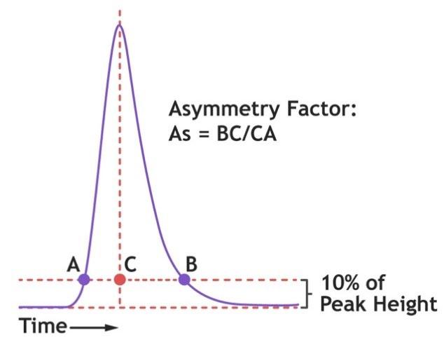
Asymmetry determination
Determine the asymmetry (As) factor as follows:
Where ‘BC’ is the peak tail width at 10% peak height and ‘CA’ is the peak front width at 10% peak height.
A typical acceptable range for asymmetry factor, where resolution is required, is between 0.8–1.2. Where resolution is not critical, a range of 0.8–1.8 is typical. The required asymmetry range should be qualified for the individual process.
Asymmetry trouble shooting
As greater than the upper asymmetry limit (tailing) indicates that the column is underpacked. For asymmetry values significantly above the upper limit, aim for a higher compression factor, target a higher packing pressure (>0.15 MPa), or extend the number of CV’s that the packing flow is applied for.
As <0.8 (fronting) indicates that the column is overpacked. For asymmetry values significantly below 0.8, target a lower compression factor, or ensure that the packing pressure does not exceed 0.50 MPa.
Efficiency (HETP) determination
Determine the HETP and N values as follows:
Theoretical plates (N) value is a measure of the peak broadening and can be used to determine the column efficiency. The higher the plates value, the less dispersion and the more efficient peaks and separation. The plates (N) value is calculated by:
Where ‘VR’ is the retention volume and ‘Wh’ is the peak width at half of the peak height.
HETP (H) is used to determine the column efficiency and corresponds to the distance between each plate. HETP is calculated by:
Where ‘L’ is the length of the column (bed height), and ‘N’ is the number of theoretical plates (as calculated above).
Plate count range required for the column should be validated for each process/application. As a guide for a starting point of investigation, a plate count of >2000 N/m is recommended.
HETP trouble shooting
If the calculated plates/meter value is significantly below 2000 N/m, repack the column and repeat column efficiency testing.
The lower the HETP value (the higher the plate number), the more efficient the column is. When measured over time, the HETP can be used to monitor the column performance. If the HETP value increases, this indicates a reduction in the column performance and the column should be repacked.
OPERATING INSTRUCTIONS
Note: The following recommendations are not prescriptive and thorough investigation of these parameters at small-scale should be conducted to reveal the level of flexibility that can be tolerated with the chromatography resin, buffer, and protein combination selected.
Product formats are available for screening experiments including 96-well plate format and pre-packed column kits. See ‘Ordering information’ for more details
The following method is recommended (as a starting point) using a 10 cm bed height, 1 cm diameter column, using an initial flow rate of 120 cm/h for the column chromatography steps (5-minute residence time). Subsequent increases/decreases in the flow rate can be investigated to improve binding capacity/resolution or decrease processing times. Aim for an operational flow rate of up to 75% of the column packing flow rate.
Filter all buffers and feedstock through an appropriate filter, prior to running the column.
2. Method development
In IEX chromatography, process design can be somewhat prescribed by knowing the isoelectric point of target and differentiation from impurity populations. In HIC chromatography, relative hydrophobicity of target and impurities can be exploited. For mixed-mode chromatography, conditions for separation based on pH, conductivity, and lyotropic character need to be determined empirically.
The optimum choice of load, post-load wash, and elution conditions for MiMode® adsorbents are dependent on physicochemical properties of the target biomolecule and differentiation from impurity species in the feedstock. The tuneable nature of mixed-mode adsorbents gives greater potential to find conditions which exploit this differentiation.
2.1 Simple evaluation
Equilibrate resin with load buffer
Load at low salt (native pH and conductivity)
Load at higher salt (0.5 M NaCl added)
Load
Gradient elution (high to low pH) if bound
Gradient elution (high to low pH) if bound
For preliminary investigation into binding behavior of the resin with a given target and feedstock, it is recommended to load the clarified feed or eluate from the previous chromatography step in its native composition.
Equilibrate the column with up to 5 CV of equilibration buffer chosen to match the composition of the load sample (buffer composition, pH, and conductivity).
Loading of the sample at high and low salt levels (0 and 0.5 M NaCl added) is a quick way of evaluating the potential to leverage hydrophobic interaction/disruption of electrostatic interaction.
When loading, apply the clarified/filtered feedstock onto the equilibrated column with a recommended residence time of ≥5 minutes If a faster residence time is required for achievable run times, e.g., there is a high loading volume, we do not recommend going below a 2-minute residence time in the first instance.
Remove any non-bound material in the column with up to 5 CV of equilibration buffer, or until the UV trace returns to baseline.
Quantitation of the target and selected impurities in the non-bound fraction allow basic determination of selectivity.
Elution
If the target biomolecule is bound to the column, elute with a high to low pH gradient (recommended 0.1 pH unit per CV) collecting fractions (recommended 1 CV) of the eluate.
Characterization and quantitation of the target and selected impurities in the elution fractions allows determination of conditions where a step elution can be implemented.
2.2 In-depth method development
Load DoE
For optimum performance, where possible, load conditions should be investigated in a full factorial design of experiment (DoE) screen. This can be facilitated by use of the 96-well plate product format.
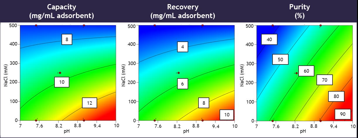
Figure 1 gives an example of a DoE for load conditions using a MiMode® adsorbent. Here, load pH and conductivity are investigated all with a common elution condition. Capacity, recovery, and purity are measured as responses in this DoE.
Figure 1 : E xample DoE responses with salt concentration and pH as factors
When loading, apply the clarified/filtered feedstock onto the equilibrated column with a recommended residence time of ≥5 minutes. If a faster residence time is required for achievable run times, e.g., there is a high loading volume, we do not recommend going below a 2-minute residence time in the first instance.
Remove any non-bound material in the column with up to 5 CV of equilibration buffer, or until the UV trace returns to baseline.
Select a strip elution condition for evaluation of binding which is compatible with the target protein. Some suggested buffers which may be appropriate for this (but not limited to) are:
• 50 mM citrate buffer pH 3.0
• 50 mM Na phosphate, 10% hexanediol, 0.5 M NaCl, pH 7.0 (any suitable buffer at ~neutral pH could be used)
Elute from the column with the selected elution buffer for 5 CV.
Gradient elution
On determining optimum load conditions, an elution system can be investigated by pH gradient elution.
Initial trial elution in ½ McIlvaine’s buffer from pH 8 to 3.8 is recommended as a starting point.
Alternative buffer systems for pH gradient should be considered to improve separation. Varying lyotropic character of buffer systems have an impact on interaction with mixed-mode ligands. Example buffer systems to evaluate with a similar pH buffering range include:
• 50 mM citrate - pH 6.0 to 3.0
• 50 mM acetate - pH 5.6 to 3.7
• ½ McIlvaine’s buffer - pH 8 to 3.8
Step elution
Once suitable separation of target has been established from evaluation of elution gradients, the process can be compressed by evaluating step elution.
By reviewing chromatograms of elution profile, select a buffer and pH which allows separation of target material from impurities. Note: These do not need to be the same buffer system. If one buffer offers better separation of impurities at a higher pH and a different buffer offers better recovery at a lower pH one (or more) buffering system can be used for the wash(es) and another buffering system can be used for the elution.
3. Cleaning and sanitization
After each use, 1.0 M acetic acid can be used as a strip post elution to remove any tightly bound target and non-target material if required.
A clean-in-place (CIP) step is recommended to avoid buildup of process impurities over multiple cycles. This maintains column efficiency, capacity, and separation performance.
If a CIP is required, use up to 5 CV of 0.5 to 1.0 M NaOH. A contact time of 1 hour will normally suffice to ensure destruction of viable organisms, although up to 5 hours contact time may be required. No less than 5 column volumes are recommended.
When a more intensive cleaning cycle is required, the following are recommended:
• If lipid fouling is a major issue, use 30%–40% isopropanol in combination with NaOH
• If iron and calcium fouling is an issue, use 50% citric acid
• If aggregated/precipitated proteins are an issue or a crude lysate feedstock has been loaded onto the column, wash the resin with either 8 M urea or 6 M guanidine- HCl
Re-equilibrate column with equilibration buffer (to remove sodium hydroxide or neutralize the resin) and check that the pH and conductivity of the column eluate is equal to that of the buffer entering the column (this is typically 5–10 CV dependent on buffer strength) before storage or reuse.
4. Storage
If the column is to be stored for future use, place the column into the storage solution (20% ethanol recommended; 0.01 M NaOH acceptable for short-term storage up to 1 week) and store at 2–30 °C in the dark.
Astrea Bioseparations also supplies larger volumes of bulk resins for cGMP development and manufacturing-scale processes.
Astrea Bioseparations also offers column packing services. For more information on this or any other inquiries, please feel free to contact us at sales@astrea-bio.com.