Replacing the Wetted Flow Path
This manual describes the procedures necessary to replace the wetted flow path components.
Figure 1.1 Column schematic. Parts shown in RED are the wetted flow path components included in the Refresh Kit

Guide to Replacing the Wetted Flowpath: Evolve® 70 mm, 100 mm and 140 mm Columns 3
Kit Components
The kit consists of the following components. Please refer to the original column manual for the component materials and chemical compatibility.
Guide to Replacing the Wetted Flowpath: Evolve® 70 mm, 100 mm and 140 mm Columns 4
DESCRIPTION QTY PRODUCT NUMBER AA07CRK AA10CRK AA14CRK COLUMN REFRESH KIT Flow Tube Adaptor, 3 mm Bore 1 X X Flow Tube Adaptor, 6 mm Bore 1 X Adjuster Flow Tube, 3 mm Bore 2 X X Adjuster Flow Tube, 6 mm Bore 2 X Bottom Flow Tube, 3 mm Bore 1 X X Bottom Flow Tube, 6 mm Bore 1 X Flow Tube Seal, 4.8 mm Bore 3 X X Flow Tube Seal, 7.0 mm Bore 3 X Adjuster seal, Evolve® 70 mm 1 X Adjuster seal, Evolve® 100 mm 1 X Adjuster seal, Evolve® 140 mm 1 X Pipe spool Elbow, Evolve® 70 mm 1 X Pipe spool Elbow, Evolve® 100 mm 1 X Pipe spool Elbow, Evolve® 140 mm 1 X Flow Tube Seal, Ladish 3.83 mm Bore 3 X X Flow Tube Seal, Ladish 7 mm Bore 3 X Bed Support Assembly, Evolve® 70 mm Fixed 1 X Bed Support Assembly, Evolve® 70 mm Adjuster 1 X Bed Support Assembly, Evolve® 100 mm Fixed 1 X Bed Support Assembly, Evolve® 100 mm Adjuster 1 X Bed Support Assembly, Evolve® 140 mm Fixed 1 X Bed Support Assembly, Evolve® 140 mm Adjuster 1 X Anti Jet Disc Small 2 X X X Adjuster cell, Evolve® 70 mm 1 X Adjuster cell, Evolve® 100 mm 1 X
Guide to Replacing the Wetted Flowpath: Evolve® 70 mm, 100 mm and 140 mm Columns 5 DESCRIPTION QTY PRODUCT NUMBER AA07CRK AA10CRK AA14CRK COLUMN REFRESH KIT CONT. Adjuster cell, Evolve® 140 mm 1 X Flow cell locking clip Evolve® 70 mm/100 mm 1 X X Flow cell locking clip Evolve® 140 mm 1 X Fixed cell Evolve® 70 mm 1 X Fixed cell Evolve® 100 mm 1 X Fixed cell Evolve® 140 mm 1 X Tube, 70 x 530 mm 1 X Tube, 100 x 530 mm 1 X Tube, 140 x 530 mm 1 X Buffer Ring, Evolve® 70 mm 2 X Buffer Ring, Evolve® 100 mm 2 X Buffer Ring, Evolve® 140 mm 2 X Scale Label, Evolve® 70 mm 1 X Scale Label, Evolve® 100 mm 1 X Scale Label, Evolve® 140 mm 1 X Serial Number Label 1 X X X Evolve® Label 1 X X X Rating Plate 1 X X X
General guidelines
To disassemble and assemble the columns follow the instructions below. After reassembling the column ensure that the column does not leak by performing a hydrostatic leakage test. When assembling/dissembling attention should be paid to:
1. Always use the correct size tools. A comprehensive tool kit is provided with the original column. See table below.
2. Ideally components should be at approximately room temperature (approximately 20°C). If not, take particular care as thermal expansion or contraction may make components fit more tightly and thus more difficult to disassemble.
3. Dismantled assemblies should be rested on a clean, dry surface.
4. Pay particular care not to damage the edge of the flow cells.
5. When unpacking columns be careful not to scratch the inside of the column tubes
6. Be careful not to damage stainless steel surfaces by bumping, knocking or scratching.
7. Do not over-tighten components, and use correct torque settings as given in this guide.
8. Good engineering practices should be followed at all times and operations carried out in an approved and safe manner.
Tool
Allen Key Set
Where used
Various locations
Spanner 10 mm / 11 mm open ended 70 mm and 100 mm column flow tube connection on adjuster flow cell
Spanner 13 mm / 17 mm open ended 13 mm spanner - 140 mm column flow tube connection on adjuster flow cell
Fixed End Tool - Small 17 mm Spanner – flow tube on fixed flow cell
Torque Wrench 3/8" Drive Used with torque wrench on fixed end cell fixing screws
Allen Key Adaptor Used to set correct torque on fixed end fixing screws
Micro S/Driver Slotted 1.2 mm Used with Torque wrench to tighten adjuster flange bolts
Guide to Replacing the Wetted Flowpath: Evolve® 70 mm, 100 mm and 140 mm Columns 6
Replace the Wetted Flow Path Components.
There are three stages to replacing the wetted flow path.
1. Disassemble the column into the three main sub-assemblies.
2. Exchange the components
3. Reassembly the column and perform initial integrity checks.
Removal of Adjuster Assembly
1. Detach any pipework from the top sanitary clamp adapter.
2. Remove flange fixing bolts from the underside of the top tube flange.
3. Check that the adjuster seal is released by turning the seal actuation nut counterclockwise.
4. Lift adjuster unit out of tube unit and place it on its side on a clean workspace.
CAUTION Adjuster units are heavy. CAUTION Adjuster unit will roll.
Disassembly of Adjuster Assembly
Guide to Replacing the Wetted Flowpath: Evolve® 70 mm, 100 mm and 140 mm Columns 7
Figure 1.2 Adjuster Assembly Evolve® 100 column
1. Remove flow tube adaptor and flow tube seal.
2. Remove the seal adjust nut and spacer.
3. Slide the flow tube and seal adjust tube out of the threaded rod.
4. Remove the flow cell locking clip and retain.
5. Using the correct sized spanner remove the flow tube to expose the flow tube seal. Remove and discard the flow tube and seal.
6. Discard the adjuster bed support, flow cell and anti-jet.
Adjuster Assembly
Wetted flow path components DISCARD
Flow tube adaptor
Non-wetted components RETAIN
Seal Actuation Nut
Flow tube seals x2 Spacer
Flow tube
Adjuster mesh assembly
Adjuster flow cell and anti-jet
Adjuster seal
Disassembly of the Fixed Assembly
Stainless steel Seal adjust tube
Threaded central height adjust rod
Height adjust handle assembly
Adjust Flange
Seal setting ring
Flow cell locking clip
Guide to Replacing the Wetted Flowpath: Evolve® 70 mm, 100 mm and 140 mm Columns 8
Figure 1.3 Fixed Assembly Evolve® 100 column
1. Disconnect the pipework elbow from the bottom of the column. The pipe spool can be removed from the pipe spool clamp using a small Allen key.
2. Using the fixed end fixing tool and torque wrench, loosen each of the fixing screws, supporting the flow cell with your hand. Remove the flow cell and place it on a clean work surface.
3. Locate the flats on the process flow tube and using the correct tool remove the flow tube. Retain and inspect the flow tube seal.
4. To remove the mesh/seal assembly from the flow cell carefully prize the bed support seal from the flow cell.
5. Remove the pipe spool support clamp from the flow cell and retain.
Assembly
Sanitary Clamp Adaptor
Cell fixing screw
Flow tube seal Pipe spool clamp and fixing bolts
Flow tube
Bottom Bed Support assembly
Bottom Flow cell and anti-jet
Pipe spool elbow
Santoprene Ladish Seal
Guide to Replacing the Wetted Flowpath: Evolve® 70 mm, 100 mm and 140 mm Columns 9
Wetted Flow path components DISCARD Non-wetted components RETAIN
Bottom
Fixed
Disassembly of Tube Assembly
1. Using the correct Allen/hex key, undo the tube support rod bolts located in the top column flange and remove the top column flange. This exposes the tube.
2. Carefully remove the tube and the buffer seals. Tube Assembly
Tube
Scale
Base Ring
Leveling Stud
Tube support Rod
Top column Flange
Guide to Replacing the Wetted Flowpath: Evolve® 70 mm, 100 mm and 140 mm Columns 10
Figure 1.4 Tube Assembly Evolve® 100 column
Wetted Flow path components DISCARD Non-wetted components RETAIN
Tube
Bottom Column Flange
buffer seals x2
Support Leg
Label
Reassembly of 70 mm, 100 mm and 140 columns
Tube Assembly
1. The orientation of the tube is shown by the fitted scale label.
2. The buffer seals should be placed on the outside diameter of the tube at a distance approximately 2 cm from the end of the tube. They should be orientated as shown in the diagram below.
Figure 1.5 Diagram showing the location of the fixed bed support
3. Locate the tube in the bottom column flange. Ensure it is located centrally and evenly.
4. Replace the top column flange and locate the tube support bolts.
5. Locate the upper and lower buffer seals into the bottom and underside of the top column flange.
6. Using the correct Allen key tighten the Tube support Rod bolts located in the top column flange.
Fixed Assembly
1. Install to anti-jet in the flow cell by carefully locating the 3 pins into the ribbed face of the flow cell.
2. Install the process flow tube into the back of the flow cell. Ensure the flow tube seal is located. Tighten process flow tube using correct tools.
3. Refit the pipe spool clamp and pipe spool elbow.
4. Install the bed support/seal assembly on to the flow cell by carefully locating the bed support seal onto the flow cell. The bed support should be fitted with the smooth side facing into the column. See Figure below.
Guide to Replacing the Wetted Flowpath: Evolve® 70 mm, 100 mm and 140 mm Columns 11
Top Buffer Seal
Bottom Buffer Seal


5. Support the flow cell with your hand and locate fixing bolts. Initially, hand tighten the bolts, working diametrically opposite to ensure equal loading on the seal. Then using the fixed end fixing tool and torque wrench, tighten the bolts to the torque settings shown in the table below.
6. Ensure all pipework connections are secure. Do not over tighten.
Guide to Replacing the Wetted Flowpath: Evolve® 70 mm, 100 mm and 140 mm Columns 12
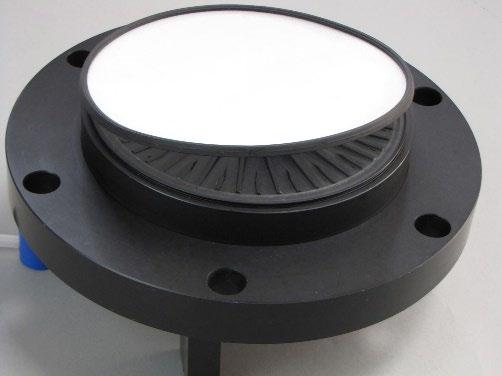
Figure 1.6 Diagram showing the location of the fixed bed support
Figure 1.7 Photograph showing the installation of the fixed bed support
Column Model Torque Setting (Nm) Torque Setting (Ft lbf) 70 mm 20 14.75 100 mm 20 14.75 140 mm 20 14.75
Smooth Side
Rough Side
Flow cell Seal
Adjuster Assembly
1. Install to anti-jet in the flow cell by carefully locating the 3 pins into the ribbed face of the flow cell.
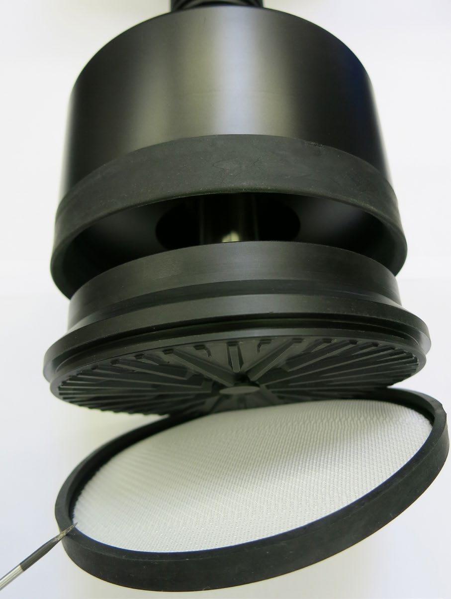
2. Install the adjuster mesh by carefully locating the bed support seal into its location groove in the side of the adjuster cell. Ensure the seal is pushed tight into the groove. The bed support should be fitted with the smooth side facing into the column (rougher side to flow cell). See figure below. Bed Support Seal
Guide to Replacing the Wetted Flowpath: Evolve® 70 mm, 100 mm and 140 mm Columns 13
Smooth Side Bed Support
Rough Side Flowcell
Figure 1.8 Diagram showing the location of the adjuster bed support
Figure 1.9 Photograph showing the location of the adjuster bed support.
3. Push the adjuster seal onto the seal setting ring. Ensure that the seal is correctly located by checking it is located in the groove in the setting ring.
4. Fit the flow tube seal into the adjuster flow cell and replace the flow tube. Use the correctly sized spanner to tighten.
5. Locate the flow tube within the stainless-steel central seal setting tube and replace the flow cell locking clip.
6. Slide this assembly into the threaded height adjust rod/ seal setting ring assembly and ensure the adjuster seal fits over the flow cell. See Figure 1.10 below.
7. Refit the spacer and central adjuster nut.
8. Lift the adjuster unit into the column tube. Alignment pins are located in the top flange to assist.
CAUTION Adjuster units are heavy.
9. Locate the flange fixing bolts in the underside of the column tube flange and tighten.
10. Replace the flow tube adaptor. To ensure the fitting is tightened correctly, align the markings on the flow tube and adaptor. Initially hand tighten and then use correct size spanner. Do not over tighten. Seal
Guide to Replacing the Wetted Flowpath: Evolve® 70 mm, 100 mm and 140 mm Columns 14
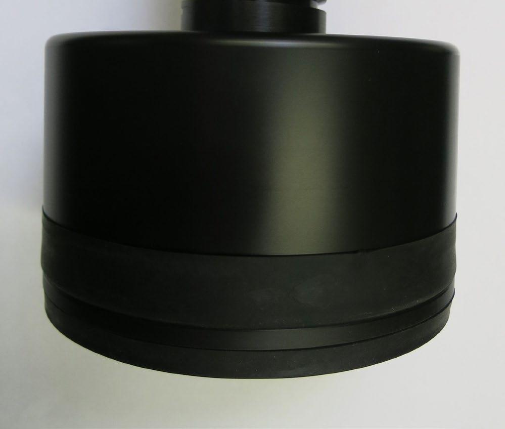
Figure 1.10 Photograph showing the final location of the adjuster bed support
Adjuster Seal
CAUTION – Over-tightening this adaptor can lead to failure of this component
Rib on flow tube
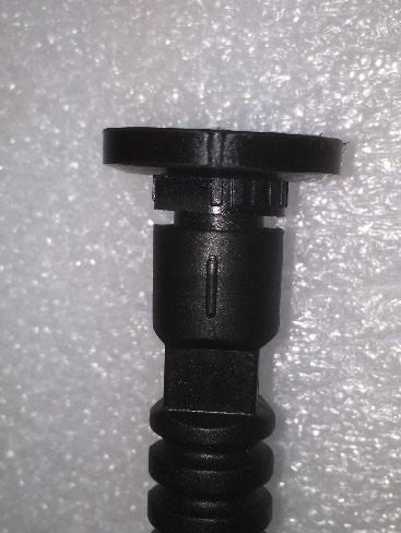
Groove on adaptor
Figure 1.11 Photograph showing the alignment of marking on flow tube and adaptor to ensure component is correctly tightened
Guide to Replacing the Wetted Flowpath: Evolve® 70 mm, 100 mm and 140 mm Columns 15
Preparing for Column Use
After replacing the wetted flow path, it is recommended these instructions are followed before use.
Hydrostatic Leak Test
The purpose of this test is to check that there are no leaks from the column and the column is ready to use. Due to the materials of fabrication, when the column is initially exposed to pressure the column will flex. It is necessary to perform the hydrostatic leak test using a twostep procedure.
1. Ensure fixed end is correctly located and fixings tightened to the correct torque setting. See table below.
2. Fill the column with WFI or high-quality water and position the adjuster at the operating bed height.
3. Ensure the adjuster seal is wetted with buffer or other suitable liquid prior to assembly. This helps ‘lubricate’ the seal to ensure correct seating.
4. Activate the adjuster seal.
5. Ensure all air is removed from the column and any connections.
6. Attach a calibrated pressure gauge to the top inlet of the column.
7. Raise the column pressure to 3 bar (45 psi) and close bottom inlet valve. Wait 15 minutes for the pressure to stabilize.
8. Open the valve and increase the pressure to maximum working pressure 4 bar (58 psi).
9. Wait 15 minutes for the pressure to stabilize. Check the pressure and ensure pressure is 4 bar (58 psi).
10. Wait for 15 minutes.
Due the nature of materials it is likely there will be a small pressure drop; however, this should not exceed 0.1 bar.
Guide to Replacing the Wetted Flowpath: Evolve® 70 mm, 100 mm and 140 mm Columns 16
Column Diameter Torque Setting (Nm) Torque Setting (Ft lbf) 70 mm 20 14.75 100 mm 20 14.75 140 mm 20 14.75
Levelling the 70 mm, 100 mm & 140 mm Columns
After installation of the fixed flow cell and before installation of the adjuster unit, it is recommended to level the column. This is achieved using the spirit level provided in the tool kit and adjustment of the levelling studs located in the foot ring of the column.
1. Place the spirit level on the tube flange and adjust the levelling studs to ensure column is level before proceeding.
There is approximately 30 mm free vertical movement available whilst still maintaining a safe amount of thread engagement.
Guide to Replacing the Wetted Flowpath: Evolve® 70 mm, 100 mm and 140 mm Columns 17