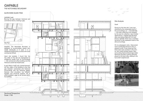
GAPABLE THE NOTCHABLE BOUNDARY
ALVIN KWEK GUAN TING
GAPABLE (adj)
Blurring the gap between historical and commerical site by creating a gap.

Gapable: The Notchable Boundary is designed to accommodate expats who reside individually or in pairs. It is a residential building that co-exists with small commercial offices.
Upon site analysis, I found that the two sides of the site are segregated by ambiguous smells from its surroundings — the commercial office building and the historical conserved shophouses.
A gap (Macro Void) was created between the two sides of the building to blur the gap between commercial and historical surroundings with the following design features: wind circulation, two different façades and structural systems. All of which enabled a gap to be formed within the building.
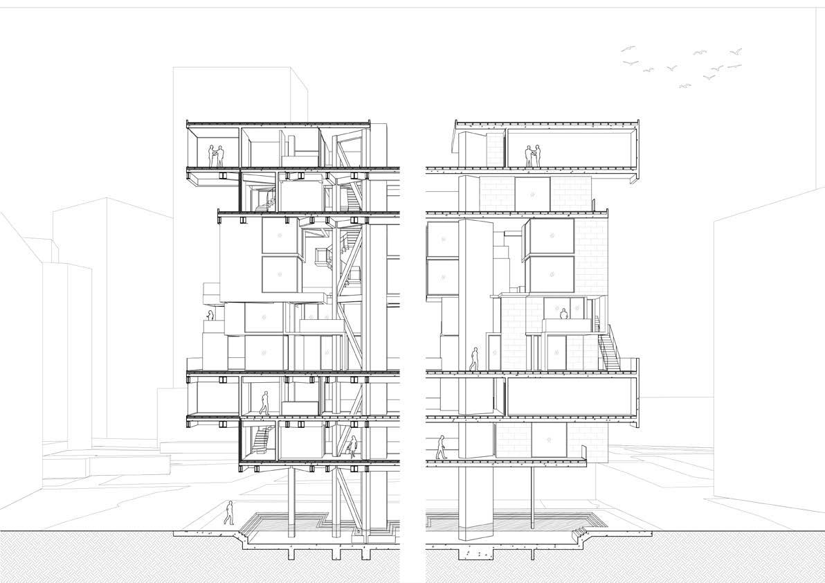
Sectional Perspective
Scale 1:150
Smell
During my first site visit, I was overwhelmed by the unbearable smell of the surroundings, as — coincidentally — the trash-collecting truck stopped by the area for collection. Upon further observations, I realised that the back alley was always filled with full trash bins by nightfall, which was a contributing factor to the unpleasant smell of the site surroundings.
On my subsequent visits, I discovered more contributing factors to the unpleasant smell. It was observed that there were many smokers in the vicinity, who mainly worked nearby. Also, surrounding food-and-beverage establishments had their cooking exhausts placed at the back alley, adding to the foul smell I experienced.


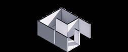
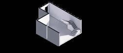
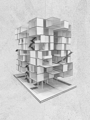
Units are formed by Aggergation Studies.
Mini Unit is formed by the negative space of Macro Unit.
All Units are either flipped, rotated or mirrored.

Number of Units: 8

UNIT CONFIGURATION
Number of Units: 4
MACRO UNIT (COUPLE) - SECTION B
(COUPLE) - SECTION B
MACRO UNIT (COUPLE) - SECTION B
SCALE 1:100
SCALE 1:100
MINI UNIT (SOHO) - SECTION A
MINI UNIT (SOHO) - SECTION A
SCALE 1:100
SCALE 1:100
MINI UNIT (SOHO) - SECTION A
SCALE 1:100
MICRO UNIT (SINGLE) - SECTION B
MICRO UNIT (SINGLE) - SECTION B
SCALE 1:100
SCALE 1:100
MICRO UNIT (SINGLE) - SECTION B
SCALE 1:100
1
MICRO UNIT (SINGLE) - SECTION A
MICRO UNIT (SINGLE) - SECTION A
MICRO UNIT (SINGLE) - SECTION A
MACRO UNIT (COUPLE) - SECTION A
(COUPLE) - SECTION A
MACRO UNIT (COUPLE) - SECTION A
SCALE 1:100
SCALE 1:100

SCALE 1:100
SCALE 1:100
SCALE 1:100


1


FACADE DESIGN


Wind Circulation is the secondary site response design.
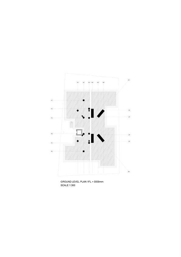
The ground level is a Micro Void that is elevated to allow better air flow throughout the building. Air is being channeled into the middle Macro Void to bring better air flow into every level.
This is achieved through the angled positioning of the pillars to supplement air flow from all directions.
At the same time, the positions of the pillars, together with the water feature at the ground level, provide passers-by with an upward visual to notice the spilt gap (Marco Void) within the building itself.


STRUCTURE SYSTEM


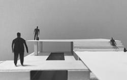
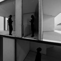
PHYSICAL MODEL
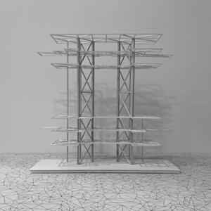


PHYSICAL MODEL

 Steel Mesh Cladding
Steel Brace
Hybrid
Terracotta Cladding
Reinforced Concrete Wall
Steel Mesh Cladding
Steel Brace
Hybrid
Terracotta Cladding
Reinforced Concrete Wall