BA3 TECHNOLOGIES PART A+B
Part A &rchitecture BCS: Liverpool Everyman Theatre
Part B: Lecture Discourse
Alexandra Muntean
Part A &rchitecture BCS: Liverpool Everyman Theatre
Part B: Lecture Discourse
Alexandra Muntean
Ecological & Environmental Evaluation Description & Analysis
1). Key Design Parameters
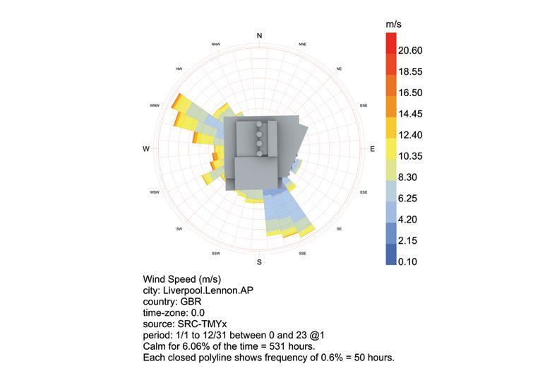
Wind: close proximity to River Mersey to the north-west, prevailing winds from NW and SW. Curtain wall facade exposed to strong winds, however the aluminium shutter panel device prevents the building from overcooling and withstands lateral live loads
Rain moderate-high precipitation throughout the year, the building fabric requiring damp proof membrane, humidity resistant building materials and advanced drainage system
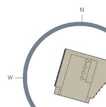
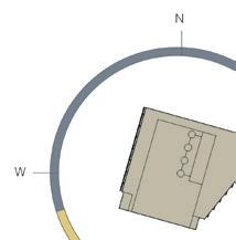
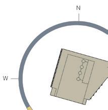
Sunlight located between two adjacent buildings, the only openings are located on the west and east elevations. Therefore, high performing glazing systems need to be designed to fully utilize the morning and afternoon sun and prevent overheating/ overcooling.
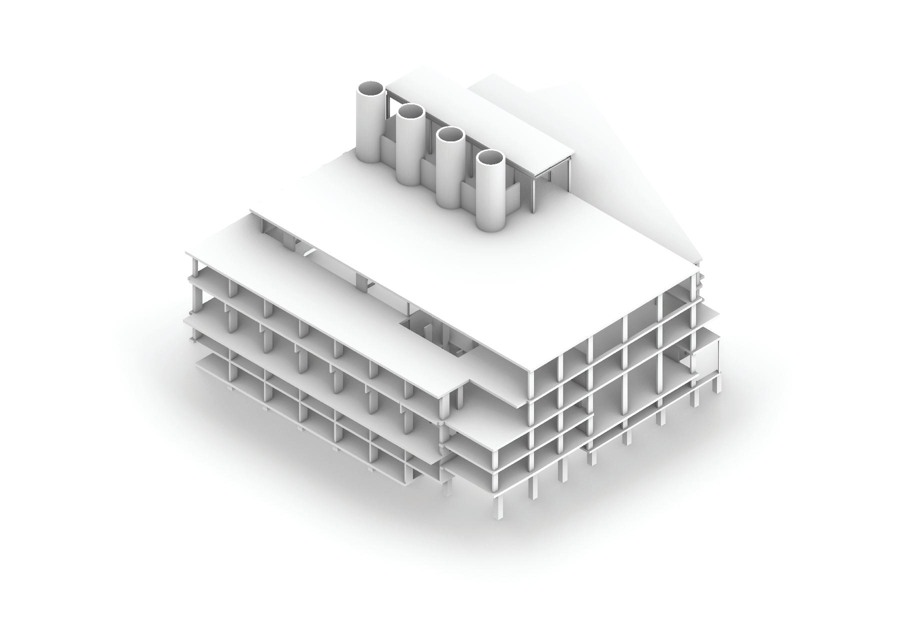
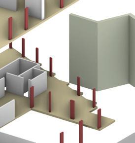
3). Building Fabric + Construction
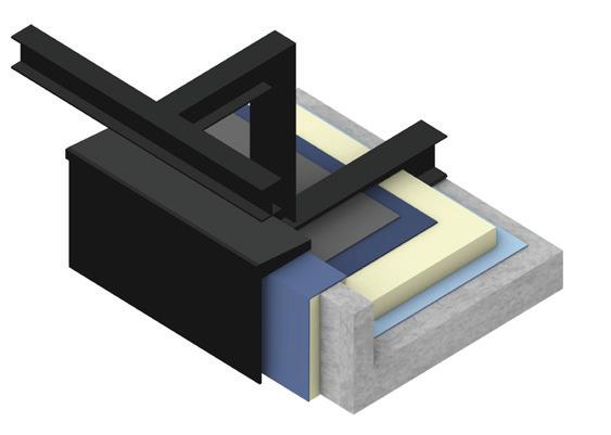
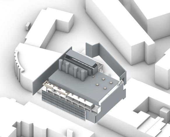
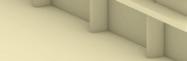
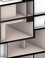
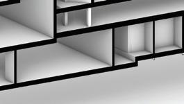
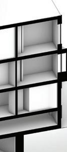
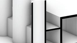
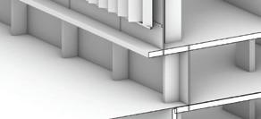
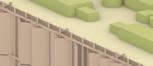
i). Isometric: Elemental Build-ups & Zones


Roof build-up
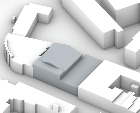
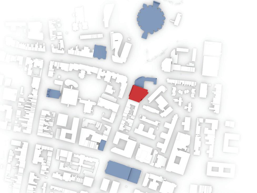
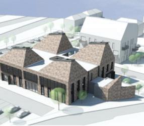
Site: located in Liverpool, on Hope Street, the theater was erected on the old theatre’s site, along with an extention of the office building on the south side.
Site Context: part of the Mount Pleasant conservation area, the theatre is part of the Grade II listed buildings (Metropolitan Cathedral, Liverpool Medical Institution, Philharmonic Hall). Along with its cultural significance, the theatre is located in the Liverpool University campus.
Rationalisation of structure:
Roof:
-reinforced concrete in-situ slab
-composite slab over fly-tower
Roof structure:
-combination of light steel trussed structure and RC columns (majority at 185x185mm) due to the large span over the auditorium
Primary Structure designed for longevity, RC frame frame was selected due to its extended life-span and thermal mass properties (the scheme aiming to utilize mostly passive strategies
-reinforced concrete columns (185x 450mm)

-in-situ reinforced concrete slabs (215mm)
-load bearing cores and shear walls (350mm thick)
Secondary Structure:
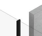
-cantelivered extruded aluminium frame (shutter panel support and window frame), used for its lighness and resistance to lateral loads (wind)
-ventilaton chimneys (brickwork)


Site Location: located in close proximity to the Salthouse dock, the building is surrounded by saltwater winds, it is exposed to increased moisture and prevailing westerly winds. It implies damp proofing, corrosion treatements and advanced ventilation strategies (air planums are designed).
Views: curtain wall system on the west elevation allows view towards Hope Street (conservation area) and the main public realm
-air plenum at roof level
Foundation type:
-pad foundations were used for stability, due to ground condition and heavy upper structure
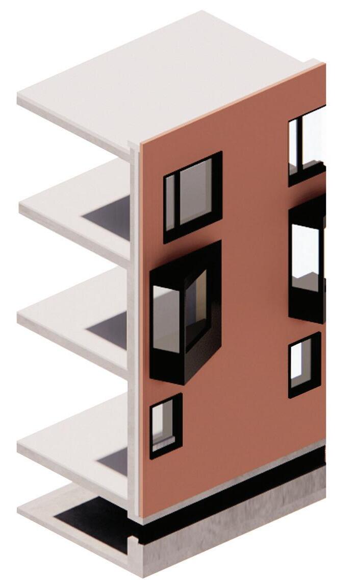
Envelope -Eastern elevation: brick cladding facade (blockwork secondary structure) -Western elevation: unitised panel facade with secondary extruded aluminium frame and aluminium panel system
Approach to Building Fabric
1. Curtain wall system (West Elevation)
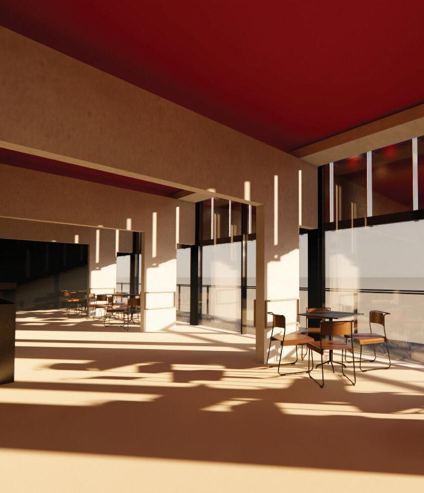
The adaptive solar shading being a main feature of the front (western facade), to reduce solar gain and prevent glare, the architect designed the elevation as a piece of public art, each shutter panel representing the silhouettes of the audience and people of Liverpool.
The selection for large panels on the western facade is motivated by the program distribution towards the front elevation. The requirement for natural daylight (bistro/cafe and office spaces) dictated the material selection and envelope system. All elements were prefabricated and assembled on site. The assembly process started after the erection of all primary structure elements.

Envelope System
Primary Structure: boardmarked reinforced concrete columns
Double-glazed windows with aluminium frame, dark bronze anodised
Secondary Structure: aluminium frame, dark bronze anodised with pivot arm and stainless steel brackets 8mm aluminium shutter panels
Ground floor build-up
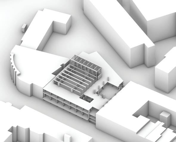
ii). General Arrangement
Prioritize building and site reuse the new theatre being built on the old theatre site and the two adjacent office building sites (see 3.ii); the available land is maximised by extending the building to the edges of the site
Create mixed-use development with density appropriate to local context: mixed use building: theatre with workshops, cafe and office spaces; program distribution is shaped by the local conditions (sun and wind)
Leave a site in better regenerative ecological than before development: the new development prioritizes sustainable strategies, using minimal mechanical systems, having low operational carbon emissions and achieving excellent BREEAM rating
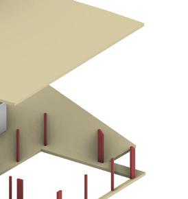
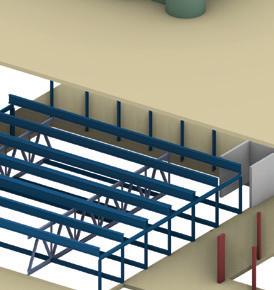
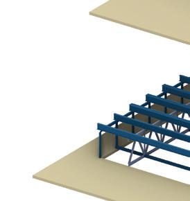
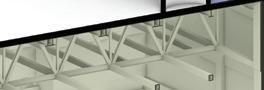
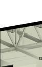
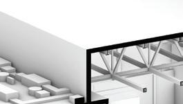
steel frame structure supported by two primary trusses and secondary beam system
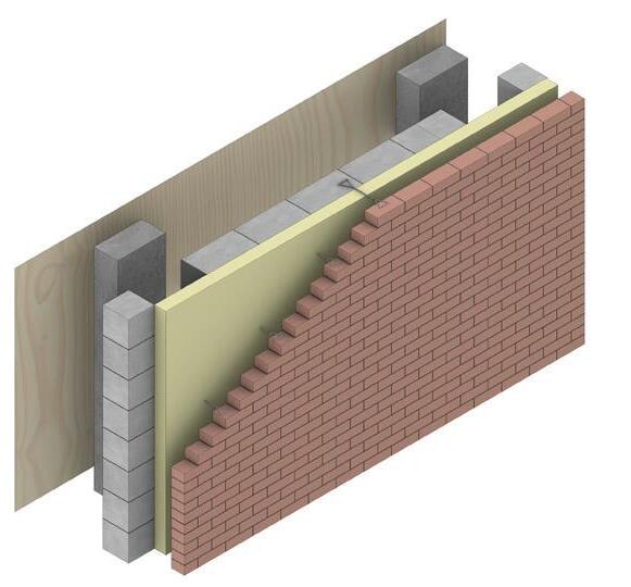
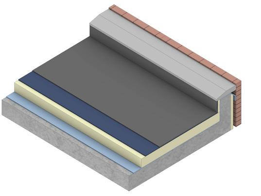
2. Brick cladding system (East Elevation)
For the eastern elevation a brick cladding system was chosen as a consequence of both program layout and the local materiality palette; as the main functions do not require great amount of natural daylight (backstage, fitting rooms), relative small openings were designed to prevent glare. To maximise the amount of natural daylight, the windows were extruded towards the east. The material choice is motivated by the urban context, as well as for the material’s thermal mass properties (0.84 J/K). The construction of in-situ brick cladding envelope started from relative eraly stages (see 3.ii).
Envelope U Value: 0.89 W/m2k


Rso: 0.06 km2/w
Rsi: 0.12 km2/w
R1: brick veneer. 0.80 km2/W
R2: insulation. 0.02 km2/W R3: blockwork. 0.11 km2/W R4: plywood. 0.01km2/W
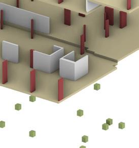
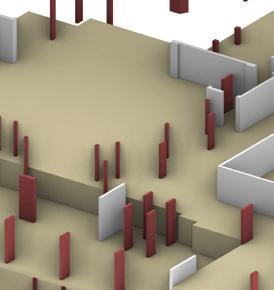
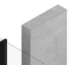
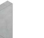
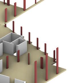
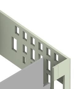
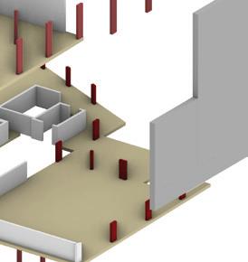
ii). Construction Strategies
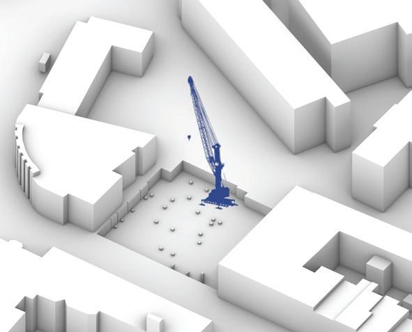
I. Demolition: Demolition of the old theatre and the two buildings on the south side. Attention given to the demolition of boundary walls to not affect the integrity of the adjacent buildings, by using non-percussive equipment and excavating out ground behind them prior to demolition. Existing boundary walls are kept in-situ and referred back to at beam position.To add, local temporary works required the formation of substructure adjacent to site boundaries. (crane fixed on site).
Reclaimed bricks were used in the latter stages for the finishings of the auditorium space
Provide hiqh quality pedestrian links: located next to the Liverpool University campus, there is a highly developed transport infrastructure, with an emphasis on pedestrian links (pedestrian paths with evenly spaced lighting (see diagram on the right)
Create comprehensive green transport plan: the theatre is situated within the cycle-firendly roads areas, while the building provides a bike storage on the ground floor, encouraging sustainable transport alternatives (see program diagram)
train and bus stations
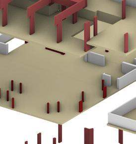
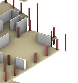
1. Demolition of existing theatre 2. Preparing the ground and laying down the foundation (mass concrete pad foundations)
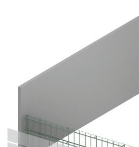
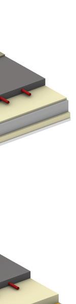
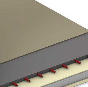
Roof build-up
Brick cladding (veneer)
Roof lining
Damp proof membrane
Insulation
Vapour Control Layer
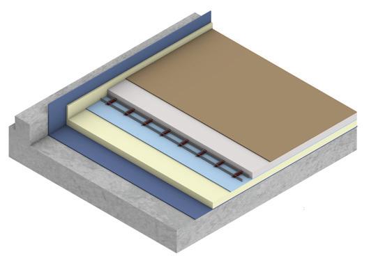
RC Slab
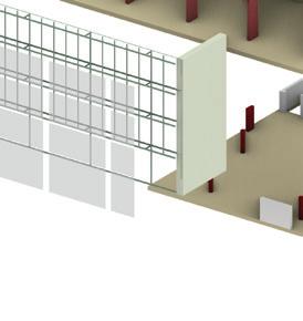
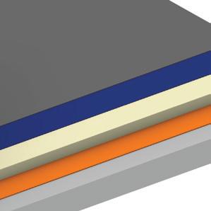
Brick cladding wall build-up
Brick cladding (venner) fixed with metal ties
Air cavity (acts as DPM)
Insulation
Blockwork
RC columns

Insulated plywood lining
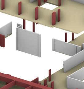
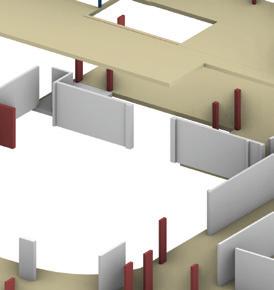
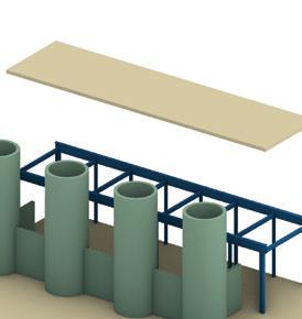
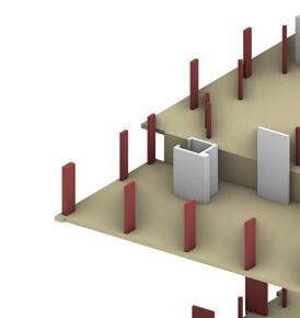
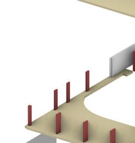
5.The last oor is erected and the steel trussedstructure is assembled. Spatial attention requiredto formation of double height spaces (workshopstudio), including an mnideck to workshop floor. Installing thrust grid and tech bridge steelwork.
Create inclusive spaces for community interaction: encouraging social interaction and cultural exchange theatre and community workshops, cafe spaces and the auditorium); for the offices there is provided an common area to encourage ideas exhange and inclusivity
Create secure places for privacy: the use of aluminium shutter panels provides privacy, while acting as a cultural manifesto for the people of Liverpool, the figures depicted on the panels being linked to the history of the theatre (see 3.i)
Create spaces for social interaction: the building represents a focal point for social interaction, being set between two main social areas (see social groups diagram)

- the RC concrete frame system allowed large spans (10.9m) through a combination of RC columns and shear walls.
is taken advantage of western winds; large manually operable windows are installed on the western elevation together with a shutter panel system
tight site constraints resulted in a subterran intake plenum ventilation system, to an unobstructed ventilation path (acoustic attenuators used in the auditorium space) through the auditorium and the four chimney situated on the rooftop (see section)
-the solar path dictated the distribution of functions and the envelope system type; public areas are situated at the front (west), while the rooms with little lightining requirements are placed at the back (east side)
Ecological & Environmental Evaluation Description & Analysis


1). Theory and Strategies
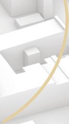
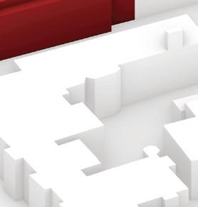
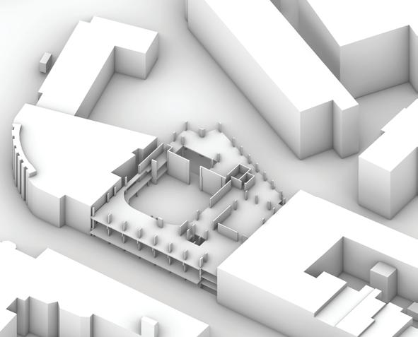
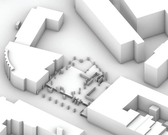
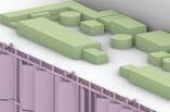
Overall Massing, Form, Arrangement


2). Environmental Design Strategies i). Isometric
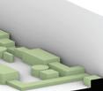
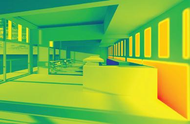
The central aspect of the theatre is the auditorium space, a key factor for the scheme being the internal environment and ventilation system. Following a low energy hierarchy of passive and active strategies, natural ventilation and mechanical systems are used. The main methods of ventilation are created by pressure differentials brought about by incident wind: stack ventilation- venturi effect.
The other functions are tailored around the auditorium space, oriented towards the east and west. Various lighting strategies are used: for the west elevation a curtain wall facade is designed together with solar shading device, while for the east side, extruded windows, oriented towards the morning sun are designed. Roof lights are placed over the office spaces. Yet the natural lighting strategy is supplemented by a complex artificial lightning system.
3). Interior Environment Analysis i). Sectional Diagrams

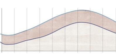
Through material choice and passive strategies there is a clear demonstration that the building was designed to respond to seasonal changes and easily adapt to them.
-shutter panels on the south prevent overheating and glare


-operable windows are used for natural ventilation, while the plenum and wind catchers act as the main ventilation system for the auditorium -cross ventilation through a combination of low and high openings -heat is stored in the reinforced concrete slabs
-Passive


High thermal performance achieved through thermal mass, double glazed coated windows and shutter panel shading device; windcatchers and air plenums used for ventilation, together with manually operable window system. -Active
For the west side, where the highly frequented spaces are located, a shutter panel system is used, which can be tilted to modulate the light and prevent glare.
For the east facade, small openings and south-east oriented windows allow natural light into the rooms while preventing overheating.
The heating system is a low temperature water heating installation generated from gas fired condensing boilers, and consisting of several types of heating distribution: underfloor heating via building management system, trench heating, wall mounted radiators (pumped heating installation) and ceiling mounted radiation panels. For the auditorium, air heaters will be located in the air plenum, to provide bulk heating.A small scale micro-CHP unit is installed in the circuit, enabling the building to produce energy and set its thermal load requirements.
Regulated areas such as kitchens and toilets will use mechanical ventilation units, in line with the miniumum part F requirements (educated guess: HVAC system).
Distribution boards are provided through the building for lightining and small power final sub circuits, the main board being located in the basement. To add, telecom network is run from the main board located in the basement. Information lacking on electrical cable distribution; educated guest is made in that on the first floor, services are run through the suspended ceiling while for the other spaces the cables are integrated in false ceilings or cast into in-situ RC slabs. The lightining and data/telecom systems are using a district network.
An incoming main water suply will be provided from Hope Street and stored in a tank, in the basement. A pump will provide the transfer of large water capacity to the third floor. Hot water is generated and stored in the plant room, on the third floor, through direct gas fired water heaters. A flow and return distribution pipework will serve fitiing throughout the building.
Rainwater stacks from the auditorium area and ‘back of house’ area will discharge in a tank located below the air plenum. The stored water will be pumped to a recyled water system. Grey water is reused to flush toilets and foul water is transported to the local sewege.
-the space are heated through a combination of passive thermal mass heating and water heating system -the void in the main western space allows heat into the upper areas


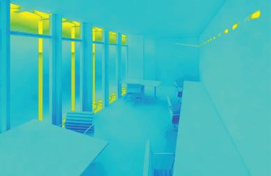
ii).
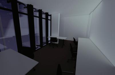
-the heat is released at nightime through operable windows and wind-catchers -shutters are open to ventilate the space and release the heat
-at nightime, shutters are closed to prevent prevailing winds inside the building -heat released by concrete slabs to regulate microclimate and prevent temperature drops
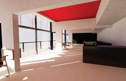
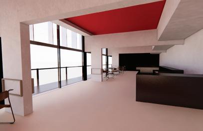
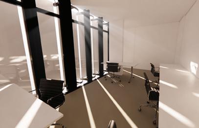
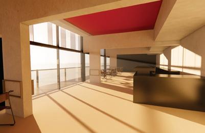
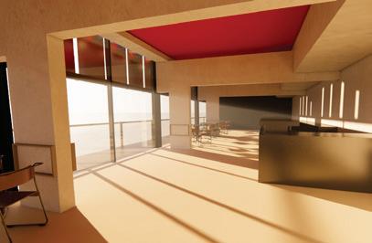
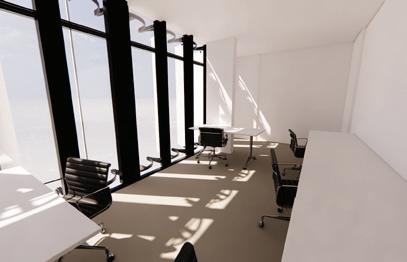
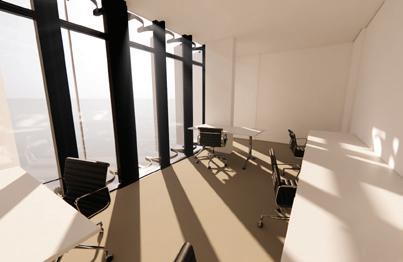
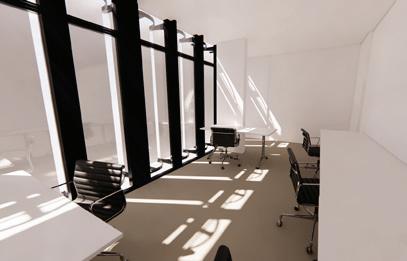
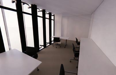
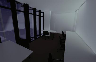
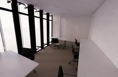
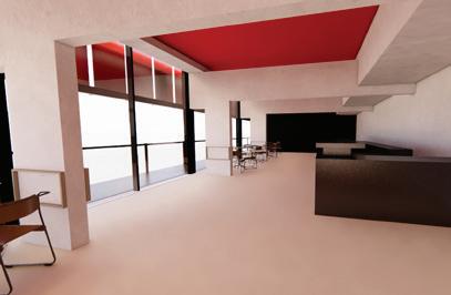
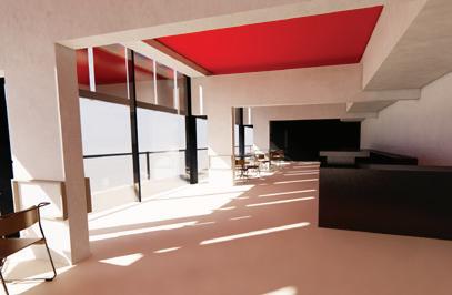
The internal quality is analysed, with regards to the efficiency of the shutter panel system and its role in two different settings: public- cafe area, and private- office. The use of panels differs from one setting to the other: for the cafe, the panels are used 1/3 of the total room’s height; for the office, the panels cover the whole window, a better light quality being achieved. Both areas are west facing.
Provide rainwater and greywater recycling rainwater collection and drainage systems designed to supply toilet flushing cisterns from a rainwater collection tank located in the basement; integrated management unit for insufficient rainfall seasons

Provide spaces with strong visual connection to outside: given the high density in the west oriented spaces, a curtain wall system is installed to allow connection to outside; the large proportion of glazing has a positive cognitive impact on occupants
Provide responsive local controls: the use of building thermal mass and stack ventilation to passively heat and cool the building (see 3.i); the shutter panel system modulates light and prevents overheating/ overcooling


Provide low flow fittings and appliances low flow fitting toilets and spray taps are provided, highly increasing the building performnace- water and energy demand; low temperature water heating system is used
Provide leak detection: leak detection sensors are installed given the high number of openings and climate conditions


ii). General Arrangement Services Distribution
Design spaces with good acoustic comfort: the shutter panels have good acoustic insulating properties to buffer noise from the main road, while for the auditorium space, reclaimed brick walls and sound proof membrane are used to absorb noise
Design spaces that are inclusive and universal accesible: a complex circulation system is provided to allow access to all spaces; lifts are located in every important area, disabled toilets are provided and hallways respect the width needed by wheelchair users
Due to the high occupancy in the afternoon, a complex lightining system is required. Artificial lights are hung with metallic installations with a strip and spot lights. According to BS 5839-1, smoke detectors are place at no more than 7.5m apart, while sprinklers are spaced at 3.5 m (max 4.9).
Given the high density, the majority of spaces require smoke detectors and sprinklers. There are 6 fire escape points complying Part B (Fire Safety) Building Regulations.
Fine tune internal environment with efficient mechanical system: the use of low temperature water heating system for trench heating, underfloor heating and radiator units (see 2.i) and additional mechanical ventilation (HVAC units)
Prioritise maximum use of onsite renewables: rain water harvesting and natural ventilation systems are used, while a solar thermal water heating system was proposed, collectors being located on the roof towards Hope Street
The vast majority of spaces have a suspended ceilings (bistro/ cafe area; entrance), plywood finish false ceilings in east facing rooms. Yet there are spaces where electrical conduits are embeded in the RC slabs (eduacted guess).
BREEAM Cettification the building achieved a 72.55% score, having the higher scores in the polution and water management sections, while scoring 69.58% for energy efficiency (a less heavy lightining network may be of great benefi for operational costs and environmental impact)
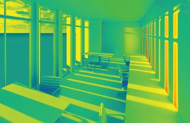
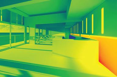

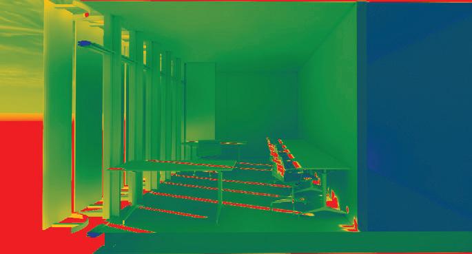
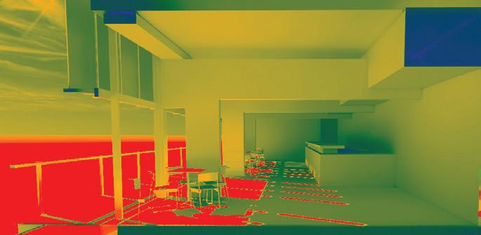
Comment: For the summer and winter solstice the office space situated on the second floor was analysed at noon and afternnon (as no light differences were registered in the morning), the panels achieving a greater performance being place on the total heigh of the room. Given the function, a highly-controlled environment is needed and the space achieves the optimal sunlight penetration.To add, being manulaly operable, the users can decide on the degree of panels’ opening. Through the solar radiation analysis, as well as internal views it can be observed the high efficiency of the shutter panels.
Critique: in the case of the cafe, the internal environement is not controlled well enough as excesive afternoon sun enters the space; the use of panels on 1/3 of the total height is motivated by accessibility to the balcony, yet other shading systems could have been used. Wst facing, solar gain and overheating are not an issue during the morning or noon, while the deep floor plan prevents excesive sunlight.
Ecological & Environmental Evaluation Description & Analysis
1). Synthesis + Argument
Detailed Assembly/ Building Fabric
Prefabricated elements
-ecologically, the vast majority of facade components are prefabricated, reducing environmental costs of on-site production; the prefabricated, unitised shutter panel system acts as a double skin, the building being designed to adapt to seasonal change and daylight
Air tight envelope
-the building shows the thoughtfull process of designing an efficient airthight envelope system; the window system is developed to reduce thermal bridges through double glazed window units and continuous insulation layer; continuous damp proof membrane prevents water, moisture infiltration
Thermal performance
-despite not having a great ecological impact, the use of high embodied carbon materials is motivated by their thermal mass properties, the building utilizing a passive heating and cooling strategy, while the operable windows and panels allow the intake of fresh air and exhaust of stale air.
-the aluminium rainscreen system improves the thermal performance, while being a non-combustible cladding material (non-combustible material class A1)
Longevity and Resilience

-the building is primarly designed for longevity, the reinforced concrete frame structure having a life span of approximately 50 years, requiring little maintenance;
-the aluminium rainscreen requires minimal maintenance and infrequent replacement while the aluminum shutter panels, the most exposed to climatic conditions have high thermal resistance and lateral load capacity (harsh winds); given the unitised elements, in case of replacement, modular parts can be replaced individually instead of large scale repairs
Transformation (retrofitting, up-cycling)
-the large span reinforced concrete frame structure extends the life span of the building, allowing free adaptation to users’ needs and alternative program
-the extruded aluminium frame allows future re-use- to be ‘up-cycled’
Reflection
The envelope minimizes potential heating and cooling requirements throught shutter panels system, which can lead to potential less operational costs. The site context support the use of unitised glazed system and the thoughfully designed aluminium panels ties the scheme to the cultural setting, while having a great impact on internal micro climate.
Yet, I believe the buidling does not reach its full sustainable and energy efficiency potential, as there are considerable heat losses from glazing. However, there is less heat loss on the eastern facade due to the thermal conductivity of concrete and brick veneer and no heat loss on unglazed facades as they are joint to adjacent buildings. As an alternative, triple glazing may be chosen to reduce heat loss and maximise the envelope thermal efficiency (from 1.6 W/m2k to 0.8 W/m2k) and thicker insulation layer to be added to covered facade elements. To add, despite the visual appereance, smaller window panels may benefi the building to lower the operational costs and prevent considerable internal temperature changes.
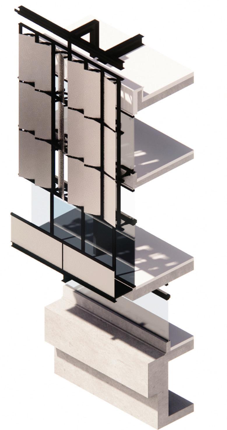
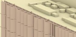
2). Integrated 3D Envelope Study
i). Isometric
Services
Hot and Cold Water system: it is assumed they sit atop of the mineral wool insulation to minimise heat loss via conduction. Trench heating is integrated witihn the floors and hot water heating pipes are cast in screed.
Electrical wires will be integrated in the suspended ceiling for the first floor, while on the other floors electrical wires may be integrated in the in-situ RC slab. Drainage system is integrated in the floor slabs from construction stage.
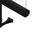
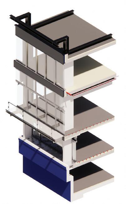
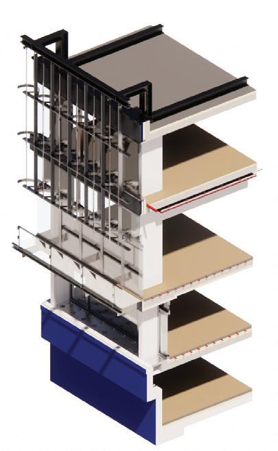
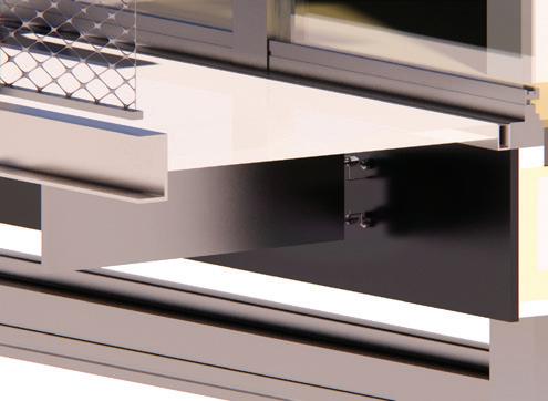
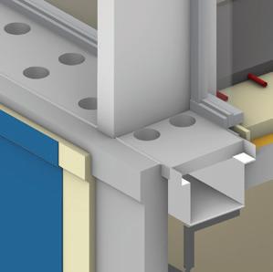
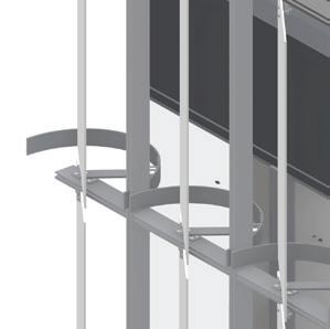
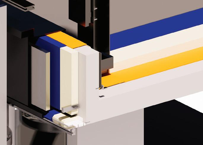
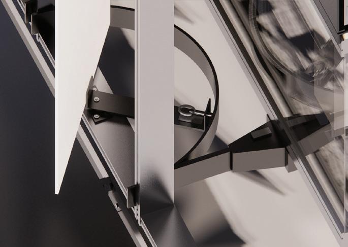
3). Junction Details
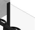
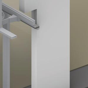
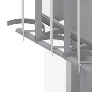
i). Wall to Roof Interface (Shutter canteliver included)
1. Painted Steel beam fixed to catilever brackets and supported by horizontal beam
2. Painted Steel bracket with LED downlight
3. Aluminium tab fixed between steel tabs
4. Dark bronze anodised, extruded aluminium frame
5. 8mm aluminium shutter panel with pivot bearing (Shutter panel set in 90 degree position)
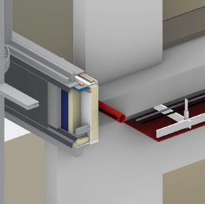
6. 6mm dark bronze anodised, aluminium rainscreen panels with steel bracket and rainscreen fixing element to concrete upstand
7. Roof lining with Damp proof membrane
8. Vapur Control layer


9. Rigid insulation (112mm)


10. 215 mm reinforced concrete slab
11. Concrete Column
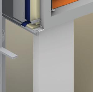
12. Double glazed operable, tilt and turn windows (extruded aluminium frame)
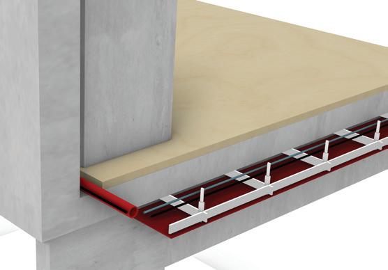
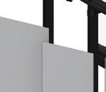
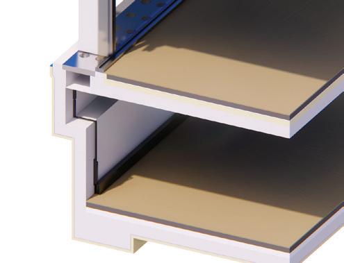
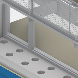
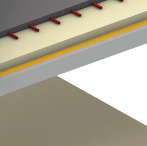
ii). Floor Slab to External Wall Detail
13. Floor lining and engineered oak floor finish
14. Screed (60mm)
15. Rigid insulation (92mm)
16. 215 mm reinforced concrete slab
17. Damp proof membrane
18. 6mm dark bronze anodised, aluminium rainscreen panels
19. Steel bracket and rainscreen fixing components to concrete element
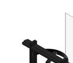
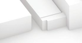
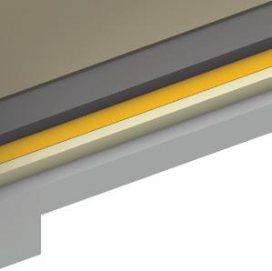
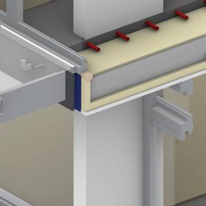
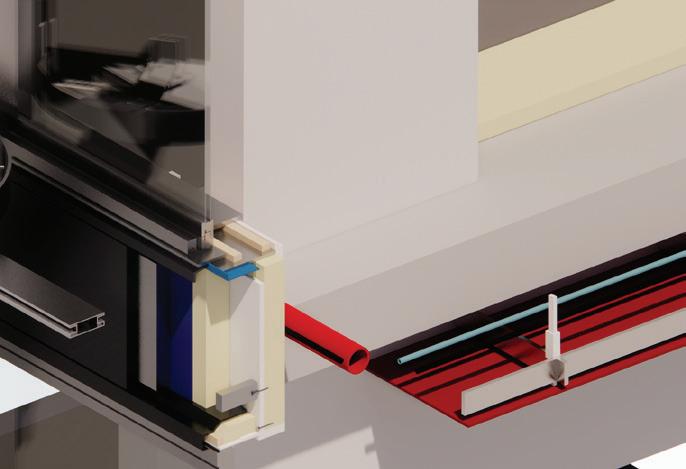
iii). Window Opening Detail ( Head + cill)
20. Oak flooring
21. Screed (60mm)
22. Rigid insulation (92mm)
23. 215mm reinforced concrete slab
24. Damp proof membrane
25. 6mm dark bronze anodised, aluminium rainscreen
panels
26. Steel bracket and rainscreen fixing components to concrete element
27. Suspended Ceiling (aluminium frame and gypsum board)
28. Weathertight MDF battens with additional thermal insulation to prevent thermal break
Fire resistance
Fire protection startegy involved non-cobustible material selection: concrete structure, aluminium rainscreen (non-combustible, the rainscreen coating only chars when exposed to fire); insulation type not mentioned, educated guess is that mineral wool was used. Fire proofed gypsum boards with red painted coating were used for the suspended ceiling finishes.
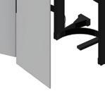
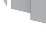
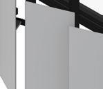
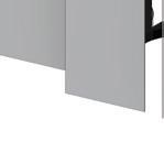
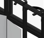
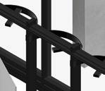
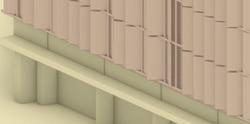
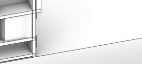
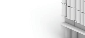
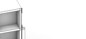
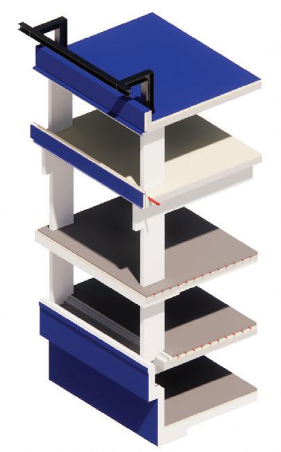
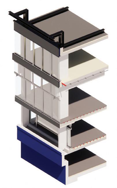
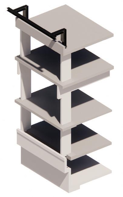
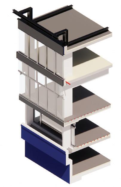
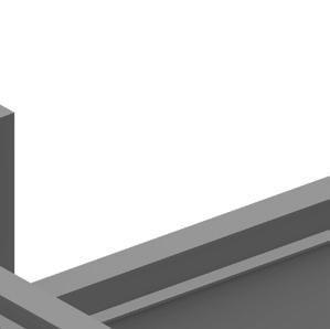
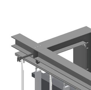
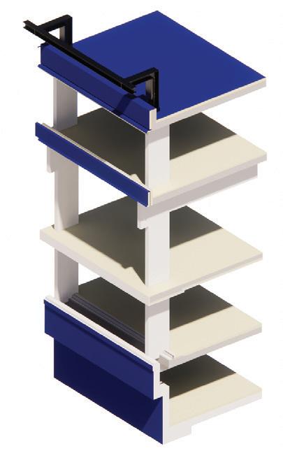
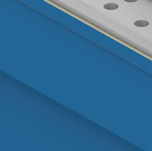
ii). Envelope Assembly ( Sequential Thumbnails)
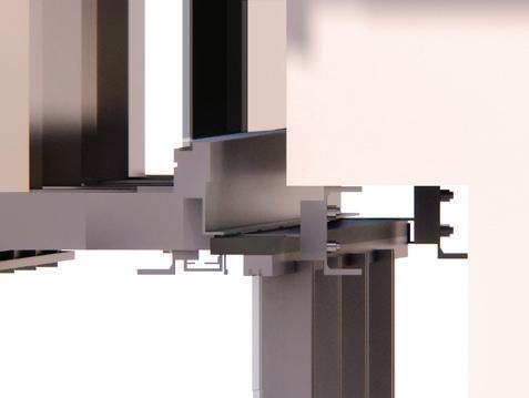
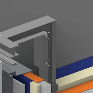
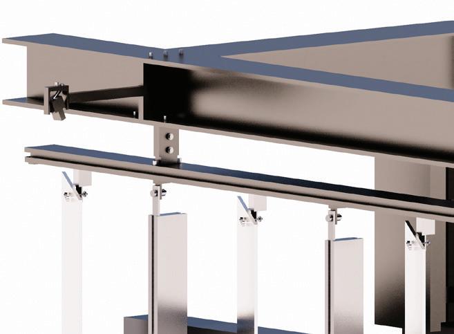
Bracket system (window frame): painted galvanised steel PFCs internally and externally fixed via thermal pad breaktransfers lateral loads from the frame to the column

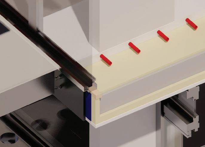
Evaluations
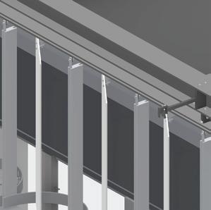
First floor gutter detail- integrated drainage system under the laminated glass panel
Net Zero Embodied Carbon Emissions
Detailing to be long life and robust choice of durable materials with great thermal performance reduce future operational costs and the consumption of natural resources to produce replacement

Offset remaining carbon emissions through recognised scheme the used of natural ventilation and passive heating and cooling strategies, together with mechanical systems

Sustainable Life Cycle Cost
Measure management and maintenance cost the used of materials which require little maintenance (aluminium rainscreen, reinforced concrete frame- exposed columns)
Measure added value of sustainable outcomes of building the use of materials with high embodied carbon allows the integration of passive heating and cooling strategies and up-cycling
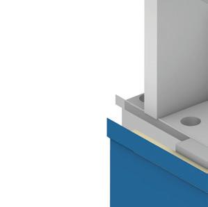
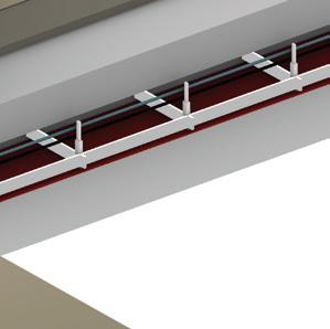
Ground level gutter detail- drainage pipes transfer the rainwater to a water tank located in the basement
Prioritise building re-use the building is designed for longevity and future re-use, therefore a large span concrete frame structure as well as easily demountable facade system are used (glazed units and cantelivered shutter panels)
Carry out whole life cycle analysis of key building systems: through demonstrated- great thermal performance, ease of maintenance, extended longevity though large-span structure and easily demountable facade system
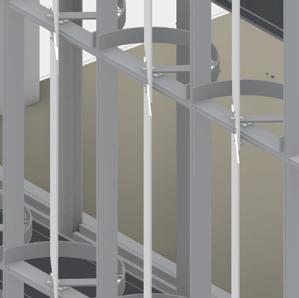
8.. Cantelivered shutter panel system
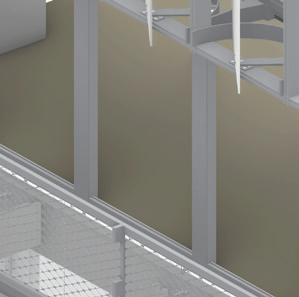
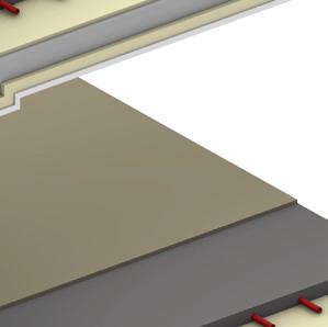
The western envelope is based on unitised elements, prefabricated components being delivered to site and easily assembled.
2. Thermal insulation and water proof membrane is added onto the reinforced concrete structure.
3. There are two main drainage systems: one later installed at the balcony level and the gutter at the ground level which is connected to a tank in the basement. Screed with underfloor heating and trench heating systems are installed.
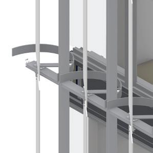
4. Extruded aluminium window frames with double glazed units are installed. For the first floor a complex bracket system is used to transfer loads to the column and secure the stability of the frame.
5. Services are installed in suspended ceilings (aluminium frame and gypsum board).
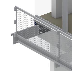
6. The steel frame balcony is fixed to the structure with steel brackets and the gutter drainge system is connected to the general network.
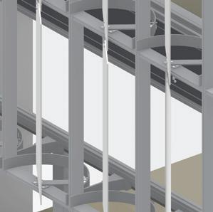
7. Cantelivered extruded aluminium frames, pivot arms and aluminium panels are assembled (fixed with steel brackets).
8. Engineered oak flooring is placed on top of screed.
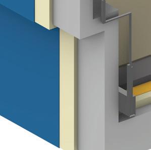
29. Pivot arm part of lower shutter bracket engaged via spung pin with hoop beadblasted finish
30. Aluminium-framed fixed and bottom hung windows, dark bronze anodised and painted galvanised steel
PFC’s internally and externally fixed via thermal break pad
31. Boardmarked concrete column and downstand beam beyong
32. Narrow profile aluminium framed sliding doors
33. Cast iron gratting with folded stainless steel gutter
34. Laminated glass with frit to top surface for translucency and slip resistance
35. Painted, galvanised-steel framing to balcony (cantelivered from floor slab)
36. Stained iroko rail with black stainless steel wire mesh
37. Engineered oak flooring
38. Screed with underfloo heating (95mm)
39. 215mm reinforced concrete slab
40. Insulated render to underside and front face of floor slab (65mm)
41. Damp proof membrane
42. 6mm dark bronze anodised aluminium rainscreen
iv). External Wall to Ground Slab Detail (Basement included)
43. Boardmarked concrete column
44. Aluminium frame double glazed window, dark bronze anodised
45. 25 mm Weathertight MDF with additional thermal insulation to prevent thermal break
46. Engineered oak flooring
47. Screed with underfloor heating (95mm)
48. Vapour control layer
49. Damp proof membrane
50. Cast iron gratting with folded stainless steel gutter
51. Reinforced concrete basement retaing wall with footing
52. Rigid Insulation with waterproof membrane
53. Screed (60mm)
54. Engineered oak floor
55. Rainwater drainage pipes
Lecture 1: Retrofit First
Date: 30/01/2023
Speaker: Glenn Ombler
Position: Lecturer at MSA, Architect
Organisation: Ombler Iwanowski Architects
Lecture 2: Healthie Greener City +
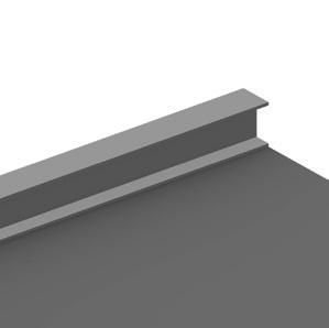
Timber in Tall Buildings
Date: 06/02/2023
Speaker: Kevin P. Flanagan
Position: Senior Associate Partner
Organisation: PLP Architecture
Lecture 3: Going Vertical (Advanced Façade Design)
Date: 03/02/2023
Speaker: Rhodri Evans
Position: Architect/ Façade Consultant
Organisation: bda
Lecture 4: Office Buildings
Date: 06/03/2023
Speaker: Laura Stafford
Position: Architect
Organisation: 5plus
Lecture 5: IDEAhaus
Date: 13/03/2023
Speaker: Ian McHugh
Position: Lecturer at MSA, Architect
Organisation: Green Triangle Studio
Critical Reflection
Design Methodology &Technological Strategy
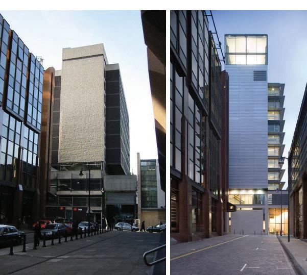
The Zenith Building represents a clear example of retrofitting where not only the economic imperative was considered when redeveloping the building, but its heritage. Considering the aims of the &rchitecture atelier, the connection with the urban context is sustained throughout the project, from spatial arrangement to the building fabric, linking the new development back to its built heritage and current urban grain. An extended investigation was conducted in documenting the old arrangement and referring to its structural strategies when extending the building: on the 10th floor, same floor to floor height, but a different form of construction (steel frame) was used. The front elevation was slightly altered, yet there is a balance of the building fabric achieved - the use of ventilated rainscreen zinc cladding and Portland stone facade, on the lower levels, linking it to the immediate context (HSBC building). To add, the project does not follow a pure mercantile approach, but takes the users in consideration by confining to modern standards, considering accessibility, and creating a conducive work environment: the reconfiguration of services (toilet facilities), by placing them next to the circulation core and the optimization of microclimate through active and passive strategies.
Responsibilities
Responsibilities encompassed the collaborative work of the architect and engineers with respect to Building Regulations, as well as the client’s brief. Responsibilities were tailored around the client’s brief to comply with the BCO guide lines and planning policy and achieve ‘Grade A’ status. Following the structural engineer evaluation, an extension with three stories was done, using steel frame structure, and for structural integrity, root piles and shear walls (reinforced supporting walls) were added. There is an emphasis on increasing fire resistance through compartment floors (achieving 120 minutes compartmentation), fire resistant windows, new fire fighter lifts and smoke evacuation systems (smoke shafts). Additionally, planning policies were regarded with attention given to the building fabric within the conservation area, and the client’s requirements. Therefore, curtain walling and ventilated rainscreen cladding were added; thermal performance was achieved through composite window system (aluminum windows with incorporated solid timber pines and double-glazed units) to reduce thermal bridges and increase efficiency. I believe the above-mentioned considerations play an important role in the design development, as the Zenith building is an eloquent example that the structural strategies are interrelated with the external building fabric and internal arrangement. Thus, these should be considered throughout my atelier project, as a significant part of the design scheme.
As part of the verification process of the architect’s responsibilities, a set of applications to the local authority and Building Regulations approval were undertaken. A great emphasis was put on Part B (Fire Safety) reinforcing the circulation core-shear walls, adding smoke control and evacuation systems (smoke shaft), assuring a minimum of 60 minutes fire resistance for walls and windows and 120 minutes floor compartmentation. Part F (ventilation) was highly considered, element which assured the building performance and the acquirement of BREAM certification (requirement from the client): air control systems (cooling units and sun shading device) as well as mechanical ventilation systems were installed. The building complies with the Health and Safety requirements, through accessibility, fire safety and structural stability.
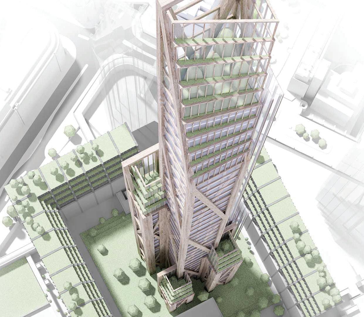
The EDGE building represents an eloquent example of an energy-efficient scheme, the light distribution analysis determining the form, the spatial arrangement, and the placement of circulation cores. Despite the use of concrete, through the passive and active BREAM strategies, the building achieves an overall zero carbon performance, while providing a sustainable environment and high-tech workspace for the users. To add, the building elegantly solves the need for an informal setting through the atrium which acts as the core of the building and as a transparent shell, connecting the building with the wider city skyline. Despite the use of materials with a high carbon footprint (concrete and glass), the flexible spatial arrangement and the simplicity of the envelope system makes the project sustainable both economically and socially. Moreover, the numerous timber structure projects presented in the lecture emphasize the long-term benefit of the material: the psychological benefits and carbon negative footprint. The conducted research on high rise timber towers distinguishes the practice from others as they set the scene for the future of sustainable architecture. The exemplary technological approaches taken by the practice I may implement in my studio project, my scheme focusing on tectonics and glulam structure as means of developing a setting which improves cognitive response for patients with mental health problems.
As the construction industry is responsible for more than half of the CO2 emissions, it is the architect’s duty to educate people with regards to new ways of construction, bring forward new regimes and present the long-term benefits of timber constructions and the need for an existential turn towards negative carbon footprint materials. Through a strong narrative, there is broken the misconception that to build sustainably, there must be an extended building cost, while enhancing the social driver for the development of these projects. As an example, modular timber constructions represent a low-cost efficient scheme, given the fast assembly process, while being environmentally and socially sustainable. To add, given the vulnerabilities of modular schemes, it is the architect’s responsibility to test the design before implementing a new technology on site, to prevent any hazards (mainly fire safety measurements). If the scheme does not live up to the expectations, it may temper the reputation of the architect and attract reluctance to further develop the scheme. Doubts may arise over the viability of timber towers as the fire compartmentation, timber life cycle (after its use, timber its burnt releasing CO2 back into atmosphere) and structural integrity (rotting, insect infestation) have not been addressed yet, especially for high-rise buildings.
Compliance
There have been made great steps towards sustainable architecture, through the RIBA sustainable outcomes and the direction to educate prospective architects about the topic. Yet, as already set out, the implementation of timber schemes, especially in the restrictive settings of the UK may attract questions regarding planning policies and compliance to fire safety regulations (approved document B). Given the untested building methods for towers built entirely from timber, planning policies have not been set out yet, which makes the proposed concept to not advance to construction stages. Therefore, there is a great gap between concept and implementation of complex timber scheme, which seem to be too advance for the current regulatory consideration for sustainable buildings (approved document L).
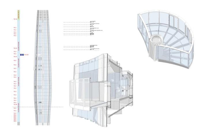
A thoughtfully designed skin articulates the architectural space, influencing not only the commercial success of the project, but the overall performance of the building, when considered as an integrative part of the design. The &rchitecture atelier follows this approach, inciting us to consider the façade as a key element of the design narrative and spatial dramaturgy. Rhodri provided a wealth of information on facades, going beyond the visual appearance, discussing the constructional principles and project risks. He elaborated on unitised panel systems as a common and efficient solution for high-rise buildings. What I found particularly insightful was the thoughtful considerations behind the design of prefabricated components for a seamless joints system and homogenized faced appearance, and efficient assembly process (regarding the modular façade system for the Capital Dock project). The heuristic approach of selecting material may be transfered to my atelier project as it is a demanding process to develop the right envelope system.
Responsabilities encompass the collaboration with different parties (contractors), but mainly with the architect, to deliver the envisioned scheme. The façade consultant has to take on the responsibility to ensure that the product will perform as required. In the case of modular elements, the architect needs to test and simulate the design before deciding on a final system. I was excited to see that bda uses mock-up models as the main medium of testing which enables a detailed analysis of the implications of new technologies. The visual appearance (glazed panel colour) and structural strength to lateral loads, are tested. In the case of mass manufacture, it is critical to test the elements before implementing it on site, as it could conclude in a mass error; there was given as an example the MECD façade testing, where the mock-up model prevented the manufacturing of façade components which failed the initial testing. To add, believe the façade consultant has the responsibility to advise the architect about the material selection, considering its properties, costs and its viability, evaluating the building performance and improving its quality (the use of glazed terracotta tile instead of glass panels was given as an example).
Compliance
Following the Grenfell fire, fire compliance is becoming more restrictive and a main concern is attributed to facades as the main fire spread element. Given the heightened risk in high-rise buildings, the regulations were supplemented with additional requirements and the set of non-combustible materials (external cladding- A1) have to be followed. To add, from the engineers’ perspective, materials with a long life-span and minimum maintenance are chosen upon low embodied carbon materials. Yet, believe there should be a change in terms of material selection and an emphasis on part Z, to achieve low passivhaus standards (with a U-value below 0.15W/m2h) and limit professionals in using materials with high embodied carbon. As the tendency is to use the already tested materials, the majority having a high embodied carbon, there should be a shift in setting out a wider range of sustainable materials in the approved documents to transition the industry to build sustainably and more thoughtully to the environment.
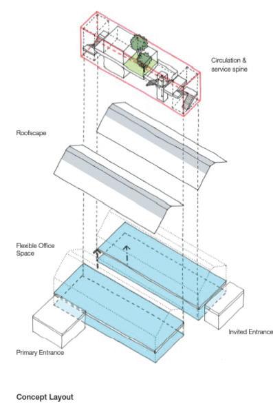
When considering office building, the interior environment seems to shape the entire scheme, yet in the lecture a wider idea was addressed: the life span of office buildings. Despite the use of materials with high embodied carbon, the material choice is motivated by the efficiency of such structures. The architect considered the longevity and flexibility of office building schemes through open floor plans and low maintenance structures, which may be more sustainable, long term, if up-cycling and transformation is considered. To add, particularly liked the Halton Housing project which is tailored around passive strategies (solar shading and stack ventilation), while acting as a revitalization tool for the neglected parts of the town. Sometimes, when I start detailing my scheme, I forget to refer to the impact of the projects on the social infrastructure, but the importance of considering the wider implications of my design project was not lost on me today. The pragmatic design approach is truly insightful; the atrium represents the core of the project, and it is a very efficient way of creating a healthy environment for the occupants, by incorporating natural light and air flow to solve the challenges of a deep floor plan scheme.
At the beginning of the lecture there were presented the architect as the advocate of different parties, from the contractors to the legislative bodies and consultants (especially fire engineers) and, in some cases, the final user. would like to highlight the mercantile approach of office design projects, where the commercial implications outweigh the sustainable considerations. I believe that the investors/clients should consider the building’s efficiency and the new sustainable outputs not as a “ticking box”, but as a mean of attracting more occupants and improve the quality of buildings. It is the architect’s responsibility to educate the client with regards to sustainable strategies and their long-term benefits. Moreover, as presented in the lecture, in the case of the Hive project, the architect has the moral responsibility to maximize the efficiency of the building, in a set (restrictive) budget: by reducing the floor-to-floor heights it allowed an additional floor level to be included, at the same building price.
Compliance
Given the building program, the architect follows the BCO (British Council for Offices) guideline and complies with the building regulation (emphasis on internal environment quality, approved doc. part F- Ventilation and part B- Fire Safety). All three case studies are tailored around environmental strategies to fit the BREEAM standards, achieving very good and excellent ratings. Yet, as already mentioned above the open floor plans as well as the materials used may benefit from long term sustainable strategies such as retrofitting and up-cycling schemes. As a parallel to the 3XN studio’s approach, where material selection and dismantling technologies are considered from the right beginning of the project to allow the re-use of construction components, the same could be done in the case of office buildings, given the flexibility of the scheme and material choice. However, regulation for materials and workmanship (Regulation 7) has not been sufficiently developed yet, to provide guidance for the end-use of high embodied carbon structures. Considering the emphasis on only operational carbon emissions, regulations for embodied carbon levels -alternative material choice should be implemented to provide healthier working environments and achieve the RIBA sustainable target.
The lecture was tailored around climate emergency and the need for a complete shift in terms of energy footprint, while the case study enhanced the key component of good practice: the building performance. Through a vast psychometric analysis, as well as a set of parameters (flooding, wind, overheating) the typical/ baseline house was analysed to develop the IDEAhaus scheme. found particularly insightful the heuristic approach of critically analyzing and reflecting upon the current housing schemes across UK before creating a new concept. The new scheme aims to create an efficient and adaptable space, through mass produced components and flexible layouts, while improving the quality of social housing. The material are thoughfully selected to lower the energy demand to miniumum and create an air thight building scheme. As my studio design scheme focuses on rethinking the healthcare system and propose an alternative scheme, it may be of benefit of thinking about thermal efficinecy in comparison to current UK healthcare building standards.
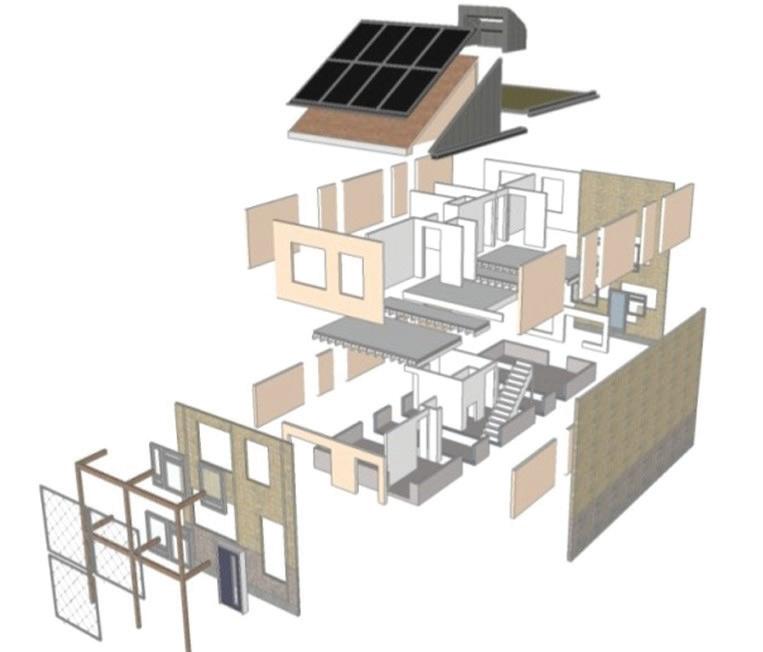
I believe every architect should question what exactly is lacking in each architecture sector and analyse the implementation of different technologies. I aim to take this practice in my future architecture career as the architect has to be analytical of his own work and the built environment. It is the architect’s responsibility to investigate the current state of housing schemes and research the implications of different construction methods. A key principle for the presented project is standardization, the mass production of core components, while providing exo-structure options and the possibility for extension. As the concept is quite new, there is a reluctance from the contractors to engage is such complex projects (reference to timber structure manufacturing contractors to engage in hybrid construction production). Hence, the architect has the responsibility to pursue different parties and inform the long-term benefit of new technological approaches and promote the scheme to attract occupants and contrators. To add, the components should be tested, before implementing the concept on site, through mock-up models, in order to avoid any large-scale errors.
The work done so far is conceptual, pioneering the transition towards sustainable and visually appealing social housing, while it seems to bear a certain level of ambiguity with regards to building regulations. It would be interesting to see how they comply to building regulations and local council approval as the components are entirely prefabricated, and the possibility of extension may require further approval documents. Yet, the detailed research and analysis which sits behinfd the scheme will help th architect pursue and obtain approval from the local council as the main motivation of the scheme is to improve the housing schemes across the UK; the project breaks the general mindset that social housings have to be poorly constructed and inefficient.