Italiana La Metallurgia
International Journal of the Italian Association for Metallurgy
n. 07/08 luglio-agosto 2025
Organo ufficiale dell’Associazione Italiana di Metallurgia. Rivista fondata nel 1909

International Journal of the Italian Association for Metallurgy
n. 07/08 luglio-agosto 2025
Organo ufficiale dell’Associazione Italiana di Metallurgia. Rivista fondata nel 1909
International Journal of the Italian Association for Metallurgy
Organo ufficiale dell’Associazione Italiana di Metallurgia. HouseorganofAIMItalianAssociationforMetallurgy. Rivista fondata nel 1909
Direttore responsabile/Chiefeditor: Mario Cusolito
Direttore vicario/Deputydirector: Gianangelo Camona
Comitato scientifico/Editorialpanel: Marco Actis Grande, Silvia Barella, Paola Bassani, Christian Bernhard, Massimiliano Bestetti, Wolfgang Bleck, Franco Bonollo, Irene Calliari, Mariano Enrique Castrodeza, Emanuela Cerri, Vlatislav Deev, Andrea Di Schino, Donato Firrao, Bernd Kleimt, Carlo Mapelli, Denis Jean Mithieux, Roberto Montanari, Marco Ormellese, Mariapia Pedeferri, Massimo Pellizzari, Barbara Previtali, Evgeny S. Prusov, Dario Ripamonti, Dieter Senk
Segreteria di redazione/Editorialsecretary: Marta Verderi
Comitato di redazione/Editorialcommittee: Federica Bassani, Gianangelo Camona, Mario Cusolito, Carlo Mapelli, Federico Mazzolari, Marta Verderi, Silvano Panza
Direzione e redazione/Editorialandexecutiveoffice: AIM - Via F. Turati 8 - 20121 Milano tel. 02 76 02 11 32 - fax 02 76 02 05 51 met@aimnet.it - www.aimnet.it
Reg. Trib. Milano n. 499 del 18/9/1948. Sped. in abb. Post. - D.L.353/2003 (conv. L. 27/02/2004 n. 46) art. 1, comma 1, DCB UD
Immagine in copertina: Shutterstock

Gestione editoriale e pubblicità Publisher and marketing office: siderweb spa sb Via Don Milani, 5 - 25020 Flero (BS) tel. 030 25 400 06 commerciale@siderweb.com - www.siderweb.com
La riproduzione degli articoli e delle illustrazioni è permessa solo citando la fonte e previa autorizzazione della Direzione della rivista. Reproduction in whole or in part of articles and images is permitted only upon receipt of required permission and provided that the source is cited.
siderweb spa sb è iscritta al Roc con il num. 26116
n.07/08 luglio-agosto 2025
Anno 116 - ISSN 0026-0843
Editoriale / Editorial a cura di Enrico Morgano - MotivexLab Rosta ..................................................................................................... pag.05
Memorie scientifiche / Scientific papers
Trattamenti termici / Heat treatments
Analysis of the rapid tempering treatment on a high-strength boron steel in the martensitic state through physical simulation
M.E. Palmieri, M. Villa, L. Tricarico . pag.07
Analysis of the applicability of Quenching and Partitioning treatment on highstrength commercial steels
M. Belfi, S. Barella, A. Gruttadauria, P. Cetto, C. Mapelli ....................................................................................... pag.16
Proprietà microstrutturali e meccaniche della lega IN718 prodotta per additive manufacturing e sottoposta a trattamento termico Proprietà microstrutturali e meccaniche della lega IN718 prodotta per additive manufacturing e sottoposta a trattamento termico
A. Ferrarotti, A. Difalco, F. Giuffrida, G. Mussino, M. Vedani, M. Baricco, A. Castellero ..................................... pag.26
Sviluppo di forgiati in acciai ad alta resistenza per applicazioni Oil & Gas e strutturali
E. Anelli . pag.36
Effect of material supply conditions on the induction hardening process parameters of carbon steels and low-alloy steels
M. Cassola, E. Bertarelli, A. Fortini, M. Merlin . pag.48
Scenari
Acciaio e metalli: dinamiche, cicli e tendenza di mercato / Steel and metals: market dynamics, cycles and trends A. Fornasini ....................................................................................................................................................... pag.58
Atti e notizie / AIM news
AIM / AIM
/


Palaexpo Veronafiere www.aimnet.it/estad2025
The knowledge and the development of the new ideas enhance progress. With the 7th European Steel Technology and Application Days 2025 (7th ESTAD 2025) AIM offers attendants and visitors the opportunity to meet, exchange their ideas, perform fruitful discussion and create new professional relationships involving technology providers, suppliers, producers and customers.
The meeting will be focused on the technological advances, changes of the supply chain involving the raw materials and energy sources, transformation of the production processes and plants to accomplish the twin transition (ecological and digital) and the new perspective of steel applications.
The registration is open. Registration fees are available on the ESTAD 2025 Conference website: www.aimnet.it/estad2025
Monday 6 October 2025 (16:00-18:30):
Early Congress registration and new on-site registration (pick-up of Conference material; possibility for speakers to upload their presentation at the slide center
Tuesday 7 October 2025: Opening/plenary session | Technical sessions | Get-together
Wednesday 8 October 2025: Technical sessions | Conference dinner
Thursday 9 October 2025: Technical sessions | Closing session
The Conference will be enhanced by an Exhibition at which companies will have the opportunity to inform all delegates of their latest developments.
Moreover, together with our partner Siderweb, we would be pleased to offer you a sponsorship package tailored to suit your own needs.
You can find on the Conference website more information together with the already present exhibitors.
Via Filippo Turati 8 | 20121 Milano MI | Italy
Email: estad2025@aimnet.it Phone: +39 0276021132 www.aimnet.it/estad2025
“"Il mondo dei trattamenti termici dei metalli è estremamente dinamico ed innovativo; è pronto a raccogliere le varie sfide globali di sostenibilità, efficienza energetica e prestazioni meccaniche."
"The field of metal heat treatmentisextremely dynamicandinnovative; itisreadytomeetthe severalglobalchallenges ofsustainability,energy efficiency,andmechanical performance."
L'evoluzione del mondo dei trattamenti termici dei metalli è un percorso continuo di perfezionamento ed innovazione, guidato dalla necessità di ottenere materiali con proprietà meccaniche sempre più specifiche e performanti, con un'attenzione crescente alla sostenibilità, all'efficienza energetica ed ai costi.
Le direzioni attraverso le quali si muove riguardano diversi aspetti come ad esempio la simulazione con l’utilizzo di software sempre più sofisticati in grado di prevedere il comportamento durante il trattamento termico, in termini di deformazioni, microstrutture e tensioni residue.
Lo sviluppo dell’Intelligenza artificiale sarà fondamentale per ottimizzare i parametri di processo in tempo reale, prevenendone i difetti e adattando i cicli termici alle specifiche esigenze del materiale e della geometria del componente finale.
La strada della sostenibilità ambientale andrà nella dire-
The evolution of metal heat treatments is a continuous journey of improvement and innovation, driven by the need to obtain materials with increasingly specific and high-performance mechanical properties, with a growing focus on sustainability, energy efficiency, and costs.
The directions in which it is moving involve various aspects, such as simulation using increasingly sophisticated software capable of predicting behavior during heat treatment, in terms of deformations, microstructures, and residual stresses.
The development of Artificial Intelligence will be crucial for optimizing process parameters in real time, preventing defects and adapting thermal cycles to the specific requirements of the material and the geometry of the final component.
The road to environmental sustainability will lead to reducing the energy consumption of heat treatment
zione di ridurre il consumo energetico degli impianti di trattamento termico, di renderli più efficienti, con manutenzioni predittive, isolamenti e sistemi di recupero del calore.
In sintesi, il futuro dei trattamenti sui metalli si prospetta estremamente dinamico e innovativo, guidato da obiettivi sempre più sfidanti in termini di resistenza ad usura e fatica che porterà ad utilizzare maggiormente rivestimenti e deposizioni sempre più sottili ma con livelli di durezza elevatissimi, per migliorare le proprietà superficiali.
Questo aspetto è cruciale nella scienza dei materiali e nell'ingegneria, soprattutto nella scelta di tecniche specializzate di misura come nano indentazioni ed analisi tribologiche approfondite, poiché i metodi tradizionali possono non essere sufficientemente sensibili o possono risentire dell'influenza del substrato.
All’interno di questo numero, i lettori, avranno la possibilità di leggere alcune memorie specifiche, presentate nell’ultimo convegno nazionale AIM di Napoli, dello scorso settembre, frutto di una comunità scientifica decisamente attiva a raccogliere tutte queste sfide globali.
plants and making them more efficient, with predictive maintenance, insulation, and heat recovery systems.
In summary, the future of metal treatments promises to be extremely dynamic and innovative, driven by increasingly challenging goals in terms of wear and fatigue resistance. This will lead to escalate the use of increasingly thinner coatings and depositions with extremely high levels of hardness to improve surface properties.
This aspect is crucial in materials science and engineering, especially when choosing specialized measurement techniques such as nanoindentations and in-depth tribological analysis, as traditional methods may not be sufficiently sensitive or may be affected by the substrate.
In this issue, readers will have the opportunity to read some specific papers presented at the last AIM national conference in Naples last September, the result of a scientific community that is extremely active in gathering all these global challenges.

DOI 10.36146/2025_0708_07
M.E. Palmieri, M. Villa, L. Tricarico
In recent years, high-strength boron steels have become increasingly important in the automotive industry, particularly for structural components such as the B-pillar. These steels, when in a martensitic state, provide excellent safety performance while enabling the use of thinner sheets, which contributes to reducing the overall weight of vehicles. However, the inherent brittleness of martensite poses difficulties during the mechanical assembly process with other car body parts. One potential solution to enhance ductility is the application of rapid tempering, which is also valued for its lower energy consumption when compared to conventional tempering treatments. This study focuses on analyzing the softening behavior and associated microstructural evolution of martensitic 37MnB4 steel when subjected to rapid tempering cycles. Three distinct heating rates (10K/s, 100K/s, and 250K/s) and two holding times (0 s and 8 s) were considered. The findings indicate that rapid tempering leads to notable softening of the steel, with the highest degree of softening observed at tempering temperatures close to, specifically a few dozen degrees higher than, the eutectoid point at equilibrium, depending on both the heating rate and the holding time applied.
KEYWORDS: RAPID TEMPERING, ADVANCED HIGH-STRENGTH STEEL, MARTENSITE, PHYSICAL SIMULATION;
The automotive sector, driven by the growing demand for energy efficiency, is increasingly utilizing advanced high-strength steels, particularly for the production of structural components. These materials provide excellent mechanical strength at acceptable ductility, effectively meeting safety requirements. Additionally, their high strength allows for the use of thinner blanks, contributing to the overall weight reduction of vehicles. This weight reduction is essential for both internal combustion engine vehicles, as it can help lower CO2 emissions, and for new electric vehicles, where it can extend battery life. Press-hardened martensitic steels are among the advanced high-strength steels commonly employed in the industry. Recent advancements have led to the development of martensitic steels capable of reaching up to 2000 MPa. These steels present superior strength levels as compared to previous generations thanks to an increased carbon content [1-3]. However, despite their high performance, these steels pose significant challenges due to the inherent brittleness of the (medium C) martensitic structure, making mechanical joining
Maria Emanuela Palmieri, Luigi Tricarico Polytechnic University
of Bari, Department of Mechanics, Mathematics and Management, Bari, Italy
Matteo Villa
Department of Civil and Mechanical Engineering, Technical University of Denmark, Produktionstorvet, Denmark
during processes like riveting, which is essential in the assembly phase, particularly problematic [4-5]. A strategy to overcome these issues involves applying a targeted, localized, tempering treatment, which can significantly improve the material's toughness, though at the cost of some strength reduction.
Rapid tempering is a moderately new tempering approach that is gaining increasing attention and that consists in subjecting the material to a fast heating cycle to a targeted temperature followed by direct cooling. This procedure opposes to traditional tempering that involves heating to the tempering temperatures and holding at this temperature for an extended period, which results in considerably larger energy consumption [6].
Rapid tempering achieves the targeted (rapid) thermal cycles via laser or induction heating [7-8]. In addition to reducing energy consumption, this procedure offers the advantage that it allows selective treatment of areas requiring greater ductility while maintaining high strength in the rest of the component [9]. When considering literature, recent studies have focused on testing the comparison of conventional tempering with rapid tempering in terms of achieved microstructure and mechanical properties [10-13]. Interestingly, some of these studies have highlighted that rapid tempering may enhance toughness at comparable strength level when compared to the conventional solution [10-13], which is noteworthy achievement for structural materials. This phenomenon was explained by the delayed tempering effects during rapid treatment, which limits the reduction of dislocation density, thereby favoring the nucleation of very fine cementite lamellae [10,13]. However, it is anticipated that such mechanism may change at varying the steel chemistry and process parameters. To the best of the authors knowledge, no studies of rapid tempering exist for the recently developed medium C, B containing, high strength steels, the last release in the automotive world. One of such grades is consequently selected for investigation in the present study. The key parameters for rapid tempering treatments are considered to be tempering temperature and holding time [10,14]. However, several studies have shown that temperature is the main factor influencing the material properties [10,14]. Since rapid tempering differs from conventional methods not only due to shorter
holding times but also because of high heating rates, an experimental analysis was conducted in this work to investigate the effects of temperature and heating rate. These parameters can be adjusted by varying the process conditions applied to the tempering treatment.
For this study we considered samples of 37MnB4 boron steel. The material was acquired as commercial grade under tradename USIBOR®2000. This steel belongs to the first generation of high-strength steels for hot stamping, with a carbon content in the range 0.3 %wt to 0.4 %wt and was supplied in form of a 1.85 mm thick sheet characterized by an initial ferritic-pearlitic microstructure coated with an aluminum-silicon layer to improve corrosion resistance. The samples, whose geometry is shown in Figure 1a, were austenitized at 950 °C for 4 minutes and then quenched in water to obtain a martensitic microstructure. Subsequently, these samples were subjected to tempering cycles using the Gleeble®3180 physical simulator, which included a heating phase, a holding phase at high temperature, and a rapid cooling phase. In this work, the heating temperature was set to 800 °C, which is within the intercritical range as to assure that the conditions yielding to maximum softening would be within the investigation window. Three different heating profiles were tested: two cycles featured constant heating rates of 10 K/s and 100 K/s, respectively, while the third employed a continuous (non-linear) heating profile with an average heating rate of 250 K/s, representative of a thermal history induced by industrial laser tempering processes. Moreover, two holding times at peak temperature were considered: 0 s and 8 s.
To ensure rapid cooling after the holding phase, compressed air was used, injected through the quenching system holes inside the test chamber of the physical simulator. Figure 1b illustrates the thermal cycles applied in the physical simulator for the cases with no holding time at 800 °C and the three investigated heating rates. Figure 1a also illustrates the experimental setup used for the tests. The sample is clamped between two copper grips inserted into two jaws cooled with a water-glycol solution, ensuring that the ends remain at sufficiently low temperatures. The copper grips enable the flow of current needed to heat the sample through the Joule effect. Temperature is
controlled using a K thermocouple, referred to as the pilot thermocouple, welded at the center of the sample (TC1) and connected to a proportional-integral-derivative (PID) controller. This system, comparing the set temperature with that measured on the sample, sends a signal to increase or decrease the voltage, ensuring that the sample temperature matches the set value. Three additional K thermocouples were welded at specific distances from the center of the sample: 5 mm (TC2), 15 mm (TC3), and 25 mm (TC4). These allow monitoring the temperature
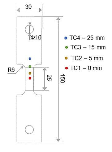
distribution along the sample during the test. Due to the functioning of the physical simulator, a thermal gradient develops on the sample, with the highest temperature at the center, progressively decreasing towards the grips. Thanks to the thermal gradient, it is possible to evaluate the effects of tempering temperature over a wide range of temperatures, from the set temperature of 800 °C as measured at the position of the control thermocouple, and down to a much lower value, around 200 °C, near the grips.
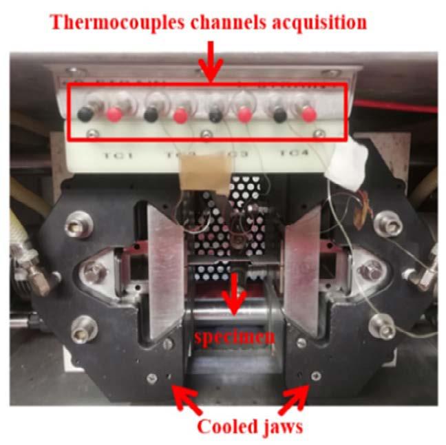
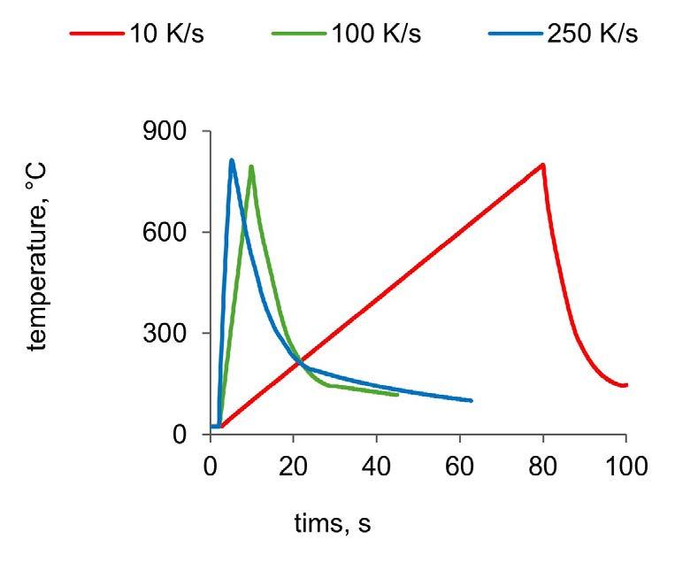
Fig.1 - (a) specimen geometry and experimental setup for physical simulation tests; (b) Thermal cycles applied in the physical simulator at varying heating rates with zero holding time.
After the physical simulation tests, the samples were ground and polished to carry out Vickers hardness tests with a 2 kgf load and a holding time of 15 seconds. These hardness tests were performed on the surface of the samples along the longitudinal axis. The distance between consecutive indentations was set to 1 mm. To obtain statistical information, 3 measurement series were carried out along the axis. The obtained hardness values were then correlated to the thermal cycle and, in particular, to the peak temperature reached during the cycle. This was estimated using a thermo-electric finite element (FE) model developed in COMSOL Multiphysics®. This model was calibrated using experimental temperature data measured with thermocouples. The model is detailed in previous works by the authors [15-16]. Thus, using the
FE approach, it was possible to accurately estimate the thermal cycle to which the sample was subjected along its entire longitudinal axis and consequently the peak temperature at each point. Finally, the microstructure obtained after the various thermal cycles was examined using a Zeiss Supra 35 scanning electron microscope (SEM) equipped with a backscattered electron detector (BSD). The samples intended for SEM analysis were previously electropolished using Struers' A2 electrolyte at 26 V for 15 seconds, employing a Struers LectroPol-5 electropolishing machine. It is worth noting that one of the main advantages of using the physical simulator for the proposed study is that with a single test it is possible to evaluate the effects of the tempering temperature over a wide temperature range.
In this respect, it should be mentioned that, while setting a specific heating rate at the control point, the heating rate varies at adjacent points. Consequently, each peak temperature is associated with a specific heating rate where the two variables are interdependent. Nevertheless, the variation in the average heating rate within a single test, between the rate measured at the center point and the actual rate recorded at the point of interest (i.e., the point of maximum softening), is lower than 20%. This difference is negligible when compared to the variations applied in separate tests.
In this section, the results obtained from the physical simulation tests are presented and discussed with a focus on the correlation between thermal cycle parameters and the material's response in terms of microstructure and hardness. The analysis aims to highlight the influence of both temperature and heating rate on the mechanical properties, providing insights into the material's behavior
under varying process conditions.
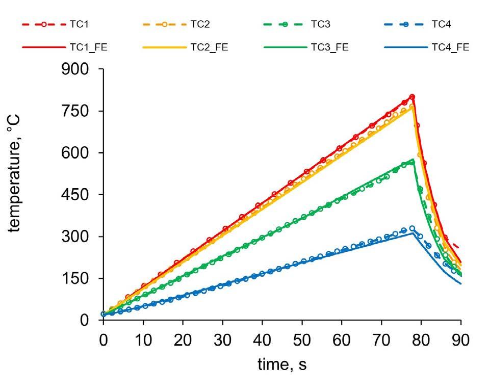
Figure 2a displays the thermal cycles recorded by the four thermocouples welded onto the specimen subjected to a tempering cycle with a heating rate set to 10 K/s and no holding time (0 s). It can be observed that under these test conditions, the material heats up, reaches a peak temperature, and then rapidly cools down. Moving from the center of the specimen toward the grips, the peak temperature decreases. Moreover, it is also noticeable that the cooling rates vary.
Analyzing the peak temperatures of this cycle as a function of the distance from the specimen's center, yields the curve indicated by circular markers in Figure 2b. The profile of peak temperatures as a function of distance was numerically derived and is represented in the figure with a continuous line. The numerical model accurately predicts peak temperatures in the range of interest (200–800 °C), with the difference between measured and FE model temperatures never exceeding 20 °C.
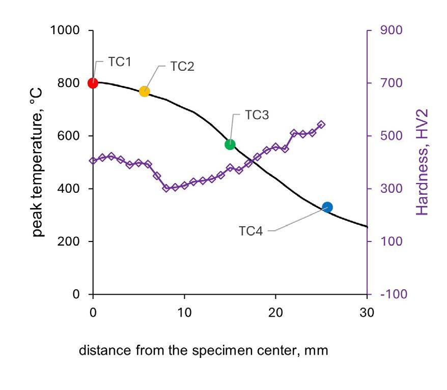
Fig.2 - a) Numerical and experimental thermal cycles with a heating rate of 10 K/s and a holding time of 0 s; (b) Numerical and experimental profiles of peak temperatures and hardness as a function of the distance from the specimen center.
The experimental hardness curve corresponding to the tempering cycle with a heating rate of 10 K/s at the control point and a holding time of 0 seconds has been superimposed onto the graph in Figure 2b. Starting from the center of the specimen, the hardness decreases, reaches a minimum value, and then increases again
toward the edges.
To correlate this trend with the metallurgical phenomena occurring in the material, Figure 3a presents the hardness profiles as a function of the peak temperatures calculated using the FE model. The results indicate that the tempering temperature is the dominant parameter
in determining the hardness of the material after the treatment, while the heating rate has a minor effect. The hardness does not follow a monotonous trend with respect to temperature. Instead, as the peak temperature —and thus the tempering temperature— increases, the hardness initially decreases, reaches a minimum point, and then rises again. This indicates that near the turning point of the hardness profile, a condition of maximum softening is achieved. Specifically, the minimum hardness value is approximately 300 ± 3 HV2, independent of the heating rate. This corresponds to a softening of more than 50% compared to the initial martensitic hardness of 633 HV2. It is noteworthy that maximum softening occurs for all three cycles at temperatures close to 730 °C, which is near the eutectoid temperature for C-steels.
From a metallurgical perspective, once the eutectoid temperature is exceeded during heating, the conditions for austenite formation (re-austenitization) are met, making it possible for the steel to undergo new hardening
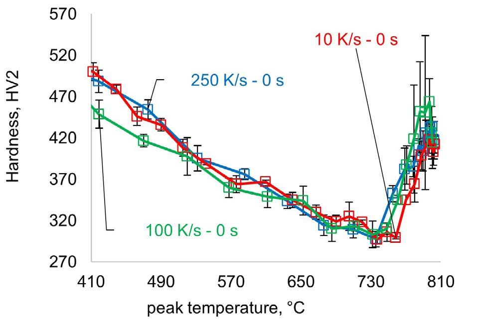
mechanisms during subsequent rapid cooling. For the thermal cycles considered, hardness increases because the (newly formed) austenite transforms back into fresh martensite. The extent of this phenomenon depends on the amount of austenite formed during the thermal cycle, but also on the carbon content in such austenite. In fact, the C content defined the hardness of the martensite obtained at the end of the cycle and the potential presence of retained austenite. It is anticipated that the C content is determined by the heating rate, the holding time and cooling conditions. Note that in the tests conducted, the final hardness does not reach the initial martensitic hardness level. This is because a temperature of 800 °C is not sufficient to achieve complete re-austenitization of the material. Clearly, at temperatures above the eutectoid, the martensite that does not transform back into austenite continues to temper and soften, resulting in an overall hardness lower than that of the initial fully martensitic (untempered) material.
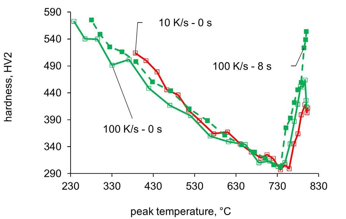
Fig.3 - (a) 2D hardness profiles as a function of peak temperature for thermal cycles with a holding time of 0 s at all investigated heating rates; (b) Hardness profiles as a function of peak temperature for thermal cycles with holding times of 0 s and 8 s at heating rates of 10 K/s and 100 K/s.
To analyze the effect of holding time, Figure 3b shows the hardness profiles as a function of peak temperature for a heating rate of 100 K/s, comparing the results for the two holding times considered: 0 s and 8 s. These data are also compared with the results for a heating rate of 10 K/s and a holding time of 0 s. The results indicate that holding time, in this explored range, does not significantly impact the tempering phenomena in the material, as the minimum hardness value remains around 300 HV2. Similarly, the peak temperature corresponding to maximum softening
remains constant, close to 730 °C. However, the holding time has a pronounced effect on temperatures above the re-austenitization range. Specifically, for a holding time of 8 s, the final hardness increases significantly, suggesting a greater tendency of the sample to harden again after exposure to high temperatures. To fully understand this behavior, a detailed kinetic analysis of the re-austenitization process, along with an accurate assessment of carbon redistribution within the microstructure during the thermal cycle, would be required. However, such an analysis is beyond the scope of the present study.
The interpretation of the hardness results outlined above is further validated by SEM analysis (Figures 4 and 5). Figure 4 shows that for all heating rates, and no holding time at high temperature, the microstructure at the control point (800 °C) is mainly composed of fresh martensite (light gray), along with a second phase interpreted as pro-eutectoid ferrite (dark gray) and small areas of tempered martensite (darker gray with white spots, i.e. carbides). A detailed quantification of these phases and an assessment of how their characteristics vary with the applied heating
rate are beyond the scope of the present study. Moving away from the center, at the point of maximum softening (i.e., minimum hardness), tempered martensite is the predominant microstructural feature observed in all samples. Figure 5 allows for a comparison of the microstructures at the control point and at the point of maximum softening, keeping the heating rate constant while varying the holding time at high temperature. It can be observed that, regardless of the holding time, only tempered martensite is present at the point of maximum softening. In contrast, at the control point, for continuous cycles with no holding time, the microstructure is predominantly composed of fresh martensite with islands of tempered martensite and ferrite. On the other hand, for a holding time of 8 s, there is an almost complete absence of tempered martensite. This behavior is consistent with the higher hardness values obtained from the hardness tests under these conditions and shows the time dependent nature of the austenite reversion process.
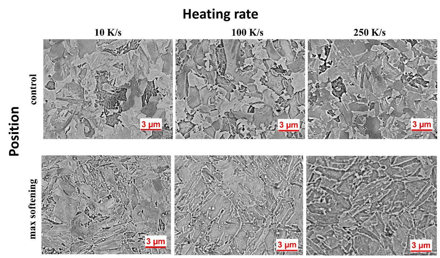
presenting the microstructure of the material versus heating rate and position along the sample for holding time at high temperature equal to 0 second.
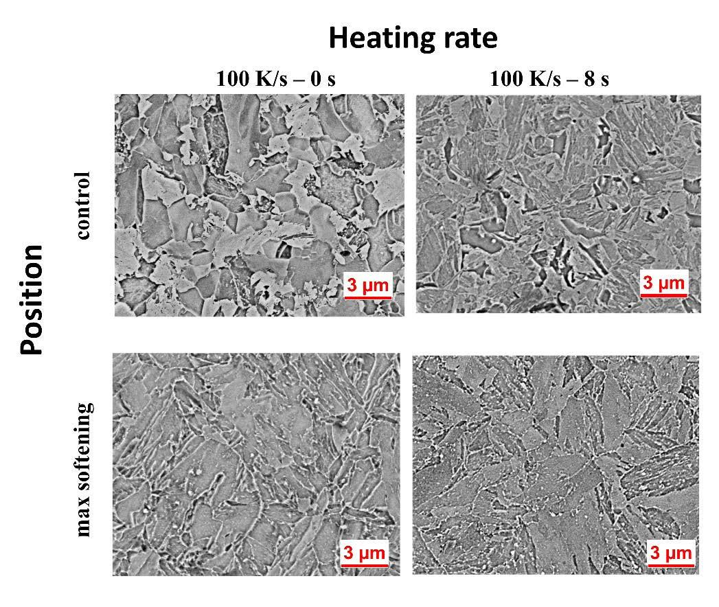
Fig.5 - BSE images as a function of heating rate and position for a holding time of 0 seconds, compared to the condition with a holding time of 8 seconds.
The results on the effects of temperature and tempering time are in line with the literature [10,14]. Specifically, temperature is the dominant factor influencing martensite softening, rather than holding time, even when the holding time is limited to just 8 s, as in this study. It is also evident that increasing the tempering temperature up to the eutectoid temperature enhances the softening effect. Data available in the literature for PHS1500 steel —a material comparable to the one used in this study, albeit with a lower carbon content— show the degree of softening achieved at 650 °C with holding times ranging from 0.2 seconds to 3 hours [17]. It was found that, at this temperature, the steel experiences a softening of 35% after 0.2 seconds and 51% after 3 hours. Although the treatment cycles in this study are continuous while those described in the literature are isothermal, the latter value is comparable to the softening achieved in the present work at the same tempering temperature but through rapid heating with no holding time. In addition to this, the present work demonstrates that the holding time becomes particularly significant when the thermal cycle temperature exceeds
that of minimum hardness.
In summary, while numerous studies have explored the effects of rapid tempering compared to conventional tempering, this work presents an efficient approach for systematically analyzing the effects of holding time, temperature, and heating rate in rapid thermal cycles. Additionally, metallurgical aspects at much higher temperatures, up to 800 °C, compared to those typically used in tempering treatments, were examined to assess their impact on hardness and microstructure. It was found that the maximum level of softening, obtained at a peak temperature of 730 °C with rapid thermal cycles and a heating rate of 250 K/s, can reduce the material's hardness by over 50% compared to the quenched condition. However, exceeding the eutectoid temperature leads to a significant increase in hardness relative to the observed minimum, and this increase becomes more pronounced with longer holding times. Thus, a rapid tempering process at a temperature below the critical value is recommended for a more stable and robust process. Exceeding such a temperature yields a reduced softening effect. Such a reduction is the most
pronounced the longer the material is kept in temperature.
Further experimental activity, i.e. X-Ray diffraction, is planned to gain a deeper understanding of the metallurgical phenomena occurring in the material subjected to rapid tempering, particularly near or beyond the temperature that results in maximum softening. The findings from these studies will be presented in future publications.
In this study, we studied the effects of rapid tempering on the martensitic microstructure and related properties of a B containing high-strength steel medium C steel, grade 37CMnB4.
The findings of this investigation are summarized as follows:
• Rapid tempering, conducted at heating rates in the range 10 K/s to 250 K/s, is a highly effective method for reducing the hardness of martensite. Specifically, a reduction in hardness of over 50% can be achieved with this method;
• Within the range of heating rates tested, the maximum degree of softening achievable is essentially independent of the heating rate;
• In the range of holding times investigated, 0 s to 8 s, it was found that the duration of the hold does not affect the level of achievable softening but impact the hardness of the material when the temperature for maximum softening is exceeded. Specifically, at a given temperature of overheating, the effectiveness of the treatment is compromised the most, the longer the holding time;
• It was established that maximum softening is achieved by treating the material at a temperature close to the eutectoid temperature. This observation aligns with theoretical expectations regarding the behavior of carbon steels;
• The application of a physical simulator, combined with temperature profile simulation using finite elements, proved to be particularly useful for the fast mapping of treatment parameters.
[1] Chen W, Chu X, Li F, Liu J, Lu H, Kuang S, et al. Microstructure and mechanical properties of a novel ultra‐high strength hot‐stamped steel with high hardenability. Steel Res Int. 2022;93(9):2200232.
[2] Zhao Y, Yang D, Qin Z, Chu X, Liu J, Zhao Z. A novel hot stamping steel with superior mechanical properties and antioxidant properties. J Mater Res Technol. 2022;21:1944-1959.
[3] Jin X, Gong Y, Han X, Du H, Ding W, Zhu B, et al. A review of current state and prospect of the manufacturing and application of advanced hot stamping automobile steels. Acta Metall Sin. 2020;56(4):411-428.
[4] Zhang Y, Yi R, Wang P, Fu C, Cai N, Ju J. Self‐piercing riveting of hot stamped steel and aluminum alloy sheets based on local softening zone. Steel Res Int. 2021;92(4):2000535.
[5] Reich M, Osten J, Milkereit B, Kalich J, Füssel U, Kessler O. Short-time heat treatment of press hardened steel for laser assisted clinching. Mater Sci Tech. 2014;30(11):1287-1296.
[6] Canale LC, Yao X, Gu J, Totten GE. A historical overview of steel tempering parameters. Int J Micro Mater Proper. 2008;3(4-5):474-525.
[7] Soriano C, Alberdi G, Lambarri J, Aranzabe A, Yáñez A. Laser surface tempering of hardened chromium-molybdenum alloyed steel. Procedia CIRP. 2018;74:353-356.
[8] Ahn ST, Kim DS, Nam WJ. Microstructural evolution and mechanical properties of low alloy steel tempered by induction heating. J Mater Process Technol. 2005;160(1):54-58.
[9] Järvenpää A, Jaskari M, Hietala M, Mäntyjärvi K. Local laser heat treatments of steel sheets. Phys Procedia. 2015;78:296-304.
[10] Euser VK, Clarke AJ, Speer JG. Rapid tempering: Opportunities and challenges. J Mater Eng Perform. 2020;29:4155-4161.
[11] Wong JD. Comparison of conventional and induction tempered steels, A. 2000-2009-Mines Theses & Dissertations. 2001.
[12] Kaijalainen A, Haiko O, Sadeghpour S, Javaheri V, Kömi J. The influence of rapid tempering on the mechanical and microstructural characteristics of 51CrV4 steel. Metals. 2024;14(1):60.
[13] Sackl S, Zuber M, Clemens H, Primig S. Induction tempering vs conventional tempering of a heat-treatable steel. Metall Mater Trans A. 2016;47:3694-3702.
[14] Rani SU, Preethi M. Effect of tempering temperature and time on microstructure and mechanical properties of 26MnB5 martensitic steel tubes. Procedia Struct Integr. 2019;14:142-149.
[15] Palmieri ME, Tricarico L. Physical simulation of laser surface treatment to study softening effect on age-hardened aluminium alloys. J Manuf Mater Process. 2022;6(3):64.
[16] Palmieri ME, Lorusso VD, Tricarico L. Laser-induced softening analysis of a hardened aluminum alloy by physical simulation. Int J Adv Manuf Technol. 2020;111:1503-1515.
[17] Ramachandran DC, Chandran D, et al. A comprehensive evaluation of tempering kinetics on 3rd generation advanced high strength steels. Materialia. 2022;26:101644.
ACKNOWLEDGMENTS
The authors would like to thank the Technical University of Denmark (DTU) for hosting Dr. Maria Emanuela Palmieri, as well as the MISE FCS Project F/310302/01-05/X56-"MANAGE5.0" and PNRR - Spoke 11 (Innovative Materials and Lightweighting) projects for the financial support that made this research period possible.
M. Belfi, S. Barella, A. Gruttadauria, P. Cetto, C. Mapelli
Quenching and Partitioning (QP) is a heat treatment for high-strength steels which aims to introduce at room temperature a microstructure composed of martensite and retained austenite. The presence of these phases provides an enhanced strength-ductility balance which are difficult to achieve with conventional treatments. This treatment is generally applied to steels with specific chemical compositions (QP steels), characterized by a high amount of silicon and manganese, which enhance the effectiveness of the treatment. However, these chemical compositions are far from those usually produced in industry. This study investigates the feasibility of applying QP on several commercial highstrength steels, whose chemistries are not specifically designed for this treatment but are already industrially produced. Criteria for material selection and process parameters are presented, and microstructural features and final mechanical properties are analyzed. The aim of the study, which is based on our previous research, is to provide guidelines for the application of QP on commercial steels, indicating limitations and possibilities.
KEYWORDS: QP, SINGLE-STEP, COMMERCIAL STEEL, AHSS, RETAINED AUSTENITE;
Quenching and Partitioning (QP) is a heat treatment designed to achieve a microstructure composed of martensite and retained austenite (RA), first proposed by Speer et al. in 2003 [1]. The presence of these phases provides a combination of high tensile strength and ductility that cannot be achieved by traditional treatments [2]. The martensitic matrix gives high tensile properties, while the soft RA improves ductility. Moreover, the latter transforms into martensite during loading through a strain-induced transformation, contributing to high tensile properties [3]. The heat treatment consists of an austenitization (seldom partial), followed by an incomplete quenching between Ms and Mf. After this step, an isothermal holding called partitioning is performed either at the same temperature (single step, SS) or at a higher one (double step, DS). During this phase, carbon diffusion from the supersaturated martensite to austenite is promoted: stabilization is obtained when the M s for austenite is moved below room temperature. Meanwhile, during partitioning, the martensitic matrix is tempered. The tempering of martensite, and the features of retained austenite, namely: amount, stability, morphology, are key factors for controlling the final properties. SS-QP treatments are performed at a lower partitioning temperature with respect
Marco Belfi, Silvia Barella, Andrea Gruttadauria,
to DS-QP, thus they feature lower carbon diffusivity which, leading to higher tensile properties but lower ductility, and longer partitioning times are needed to achieve sufficient ductility and martensite tempering. Nevertheless, SS-QP treatments are simpler (fewer process parameters) and potentially more cost-effective because they are performed in a single salt bath kept at lower temperatures (between Ms and Mf). The research presented in this work has focused mainly on SS-QP treatments.
QP steels belong to the 3rd generation of Advanced HighStrength Steels (AHSS) and are known for their exceptional combination of strength, toughness, and formability [4]. This makes them suitable for automotive applications such as body panels and structural components. The chemical composition of QP steels is typically adjusted to maximize the effectiveness of the treatment. Silicon (>1 wt.%) is usually added to suppress or at least delay carbide formation: this is an undesired phenomenon because it reduces the amount of free carbon available for partitioning [5]. Other alloying elements such as manganese or nickel are introduced as they enhance the hardenability and are austenite stabilizers. Most research in literature has focused on laboratory compositions tailored for the treatment rather than commercial steel grades already studied in the
industry, which might be interested by the combination of properties introduced by such a treatment [6,7]. The study proposed here is intended to provide a summary of our recent studies on the application of single-step QP treatment on commercial steels. The design, application and analysis on different chemical compositions is presented, with the aim of providing insight into the design parameters of the heat treatment, the mechanical properties introduced, in order to provide an overview of the results obtained and the positive features and limitations of the application of this treatment.
The selection of the material must set the conditions for an effective QP treatment. The steels were selected based on three selection criteria, namely: 1) they must be commercial low-alloyed steels used for high strength applications, 2) have sufficient carbon concentration to achieve martensite formation (%C > 0.2), and 3) have enough alloying elements to guarantee sufficient hardenability during salt bath quenching. The chemical compositions of the selected steels are presented in Table 1.
Tab. 1 - Composizione chimica degli acciai commerciali analizzati nel presente studio – Chemical composition of the analyzed steels.
In Fig. 1, the chemical composition of the selected alloys compared with a pool of compositions found in literature is presented. The focus is set especially on C-Si (Fig. 1a) and Si-Mn (Fig. 1b) contents since these elements were identified as the most relevant in QP steels. The chosen low-alloyed commercial compositions are generally
characterized by a lower percentage of Mn and Si than the QP steels studied in the literature, as the levels used in literature still cause production issues in industrial settings. However, the low presence of silicon (<1%) does not allow control of carbide precipitation during partitioning [5]. The low amount of manganese in the alloy also decreases the hardenability. As a result, a higher amount of carbon is required to compensate for these two
shortages. Hardenability was indeed identified as the most constraining factor, as the cooling rate obtained during salt bath quenching was not enough to avoid further phase transformation in C35, C45 and 20MnB5 steels: these compositions, which are represented with a red-dot in Fig. 1, are consequently considered as a lower bound limit for the chemical composition for QP application.
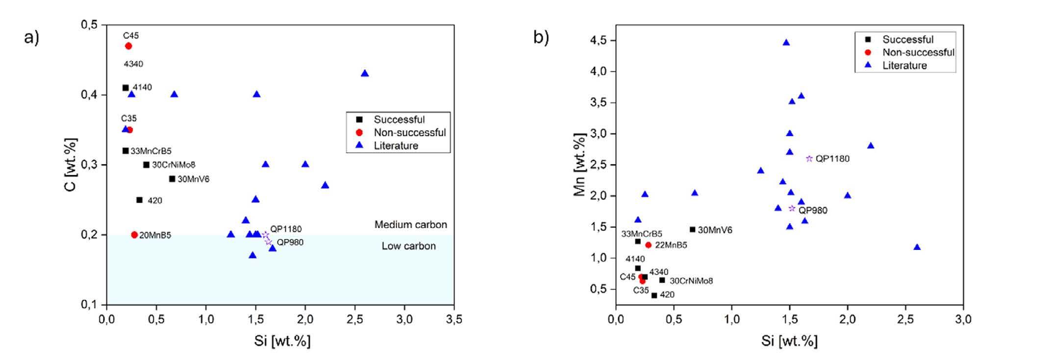
Fig.1 - Confronto tra le composizioni chimiche degli acciai commerciali scelti nel presente studio (nero, rosso) e gli acciai tratti dalla letteratura (blu) [2,5,8-21]. a) C-Mn, b) Mn-Si / Chemical composition comparison between the low-alloyed commercial compositions selected in the present study (black, red) and the steels found in multiple work in literature (blue)[2,5,8–21]. a) C-Mn, b) Mn-Si
The selection of the process parameters is crucial to introduce the desired microstructure at room temperature. The quenching temperature Tq (Tp =T q in single-step treatments) must be selected to obtain the correct amount of RA after the first quenching phase: A high Tq leads to a low martensite fraction and free carbon and thus can lead to insufficient austenite stabilization and consequently to fresh martensite (FM) formation. Fresh martensite formation must be avoided as far as possible because its brittleness reduces the mechanical properties of the alloy [16]. Moreover, a high Tq can set the conditions for isothermal bainitic transformation of austenite and carbide precipitation [22][23]. A low Tq instead can lead to an insufficient RA amount. Although Constrained Carbon Equilibrium (CCE) identifies an optimal Tq, its results are often overestimated because of the difference between the real conditions and the hypothesis of the model, namely: full partitioning, no carbide formation and fixed interface. Consequently, Ce-
lada-Casero et al. [21] identified as 15-20% the maximum amount of austenite after first quenching to maximize the effectiveness of the treatment: using the CCE model, it is possible to identify the corresponding Tq [1]. Regarding the partitioning time (tp), if too short, insufficient stabilization of RA is obtained, while excessively long times can lead to isothermal transformation of austenite [23]. The different possible cases are presented in Fig. 2. These constraints lead to a narrow operating window for SS-QP treatments. The best results for the selected steels are obtained when T q is low and t p is medium-high (in the order of 10-120 minutes) are presented in Fig. 2.
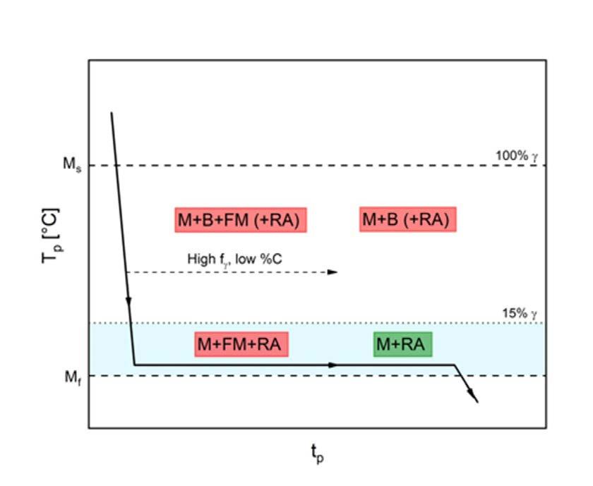
Fig.2 - Schematizzazione del trattamento di SS-QP e riassunto dei parametri di processo efficaci negli acciai studiati / Schematization of SS-QP treatment and summary of effective process parameters in the studied steels Material T q [°C] t
The typical microstructure of a QP-treated steel is presented in Fig. 3. As previously explained, the final microstructure after a SS-QP treatment is ideally composed of a tempered martensite and a fraction of stable RA. Actually, especially for commercial
30CrNiMo8 235 10-120
AISI 4140 240 1-20
AISI 4340 200-220-240 10-30
33MnCrB5 240-260 5-10
30MnV6 220-240 10-20
composition, the optimal selection of parameters can be hardly found, leading to the presence of fractions of FM and bainite. EBSD analyses are a powerful tool that can be used to clearly distinguish between phases and to study morphology and distribution of RA in the martensitic matrix.
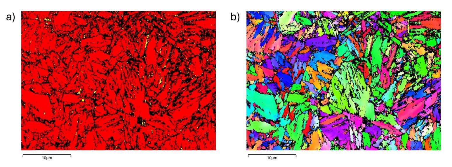
Fig.3 - Analisi EBSD su acciaio 30MnV6 trattato con SS-QP. Austenite in giallo, martensite in rosso. a) Mappa delle fasi, b) IPF / EBSD analysis on SS-QP treated 30MnV6 steel. Austenite in yellow, martensite in red. a) Phase diagram, b) Inverse Pole Figure.
In Fig. 3a, a fraction of thin RA is visible in the martensitic matrix. As SS-QP treatment feature low diffusivity, usually the stabilized thickness of RA is low, and a fine interlath or GB retained austenite is obtained, while blocky retained austenite is less present. The IPF map presented in Fig. 3b shows that the microstructure is homogeneous and non-oriented. It must be clarified that EBSD analyses always show a lower RA fraction than the one measured
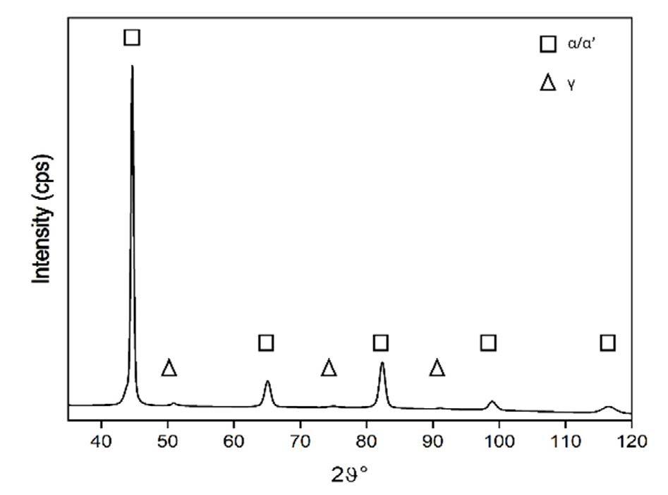
by XRD, because of the high sensitivity of RA to surface preparation and resolution issues of the machine itself, as literature has observed the nanometric dimension of some RA grains [24]. The RA fractions obtained through X-Ray diffraction for different alloys are presented in Tab. 2 along with a typical XRD spectrum for QP steels.
Tab.2 - Schematizzazione del trattamento di SS-QP e riassunto dei parametri di processo efficaci negli acciai studiati / Schematization of SS-QP treatment and summary of effective process parameters in the studied steels Material
30CrNiMo8 5-13
AISI 420 8-11
AISI 4140 4-8
AISI 4340 4-8
33MnCrB5 3-5
30MnV6 4-6
The results of the tensile tests are presented in Fig. 4. The different QP treated steels (full dots) show ultrahigh tensile properties, always above 1400 MPa. The comparison between QP and QT (half-full dots) samples shows that similar UTS values are obtained in both conditions, but the QP treated samples feature a higher ductility. A difference is observed regarding the YS (presented in Fig. 4b), which is lower in QP samples compared to the QT counterparts. This effect is due to the presence of soft retained austenite which increases the work hardening also through a decrease in the overall
yield strength. However, the comparative QT samples are designed to have a martensite tempering similar to the one given by QP through a tempering treatment performed at Tq, tp and its final tensile properties are not representative of practical applications. Therefore, these samples serve to isolate and highlight the contribution of RA to tensile behaviorThe ultra-high tensile properties shown make QP samples usually compliant to both standards regarding both the UTS and A%. Compared to QP1180 steel, higher UTS and YS are obtained, but with similar A% (especially for 30MnV6 and 33MnCrB5).
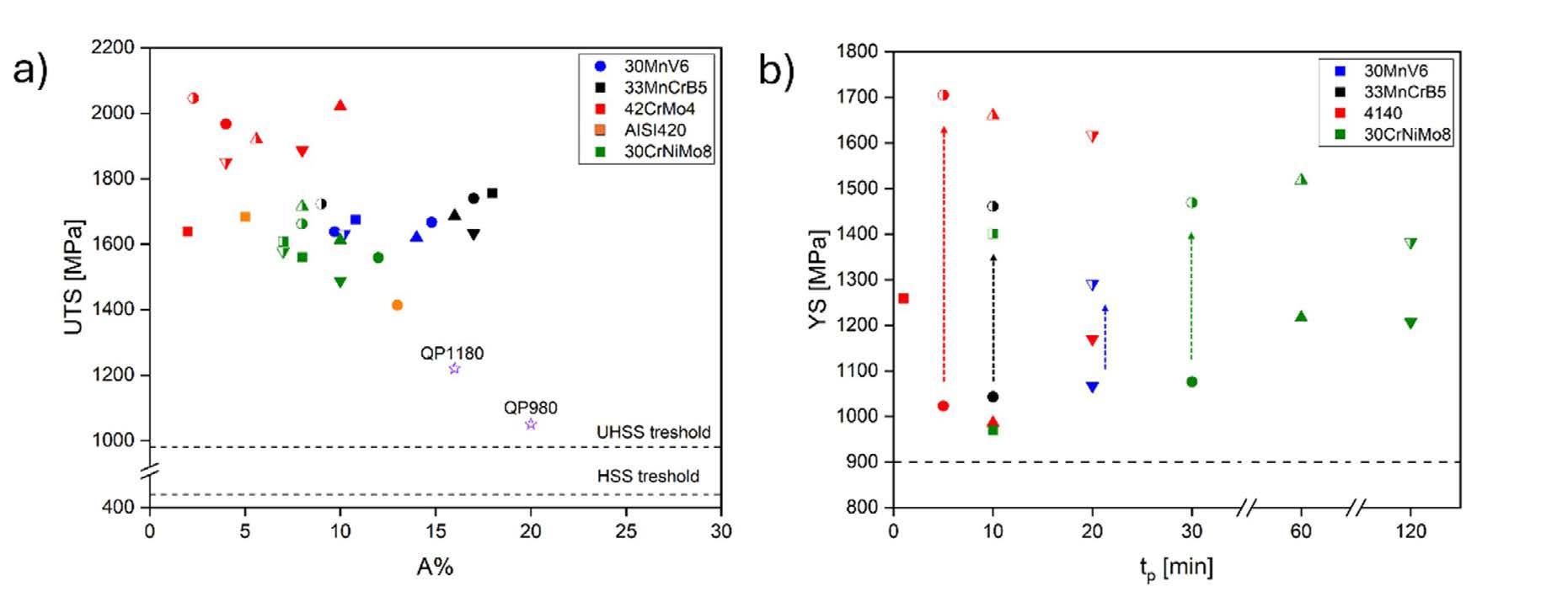
Fig.4 - Proprietà tensili degli acciai trattati. I simboli pieni corrispondono ai campioni QP. Ogni punto si riferisce al valor medio di diverse prove di trazioni. I simboli pieni a metà si riferiscono a campioni QT comparativi con la stessa tp . Le stelle viola si riferiscono a quelle degli acciai QP980 e QP1180. / Tensilecurvesoftheheat-treatedsteels.Solidsymbols correspond to QP samples. Each point represents the average result of multiple tensile tests. Half-filled symbols refer to comparative QT samples with the same tp. Purple stars refer to properties required by QP980 and QP1180 steels.
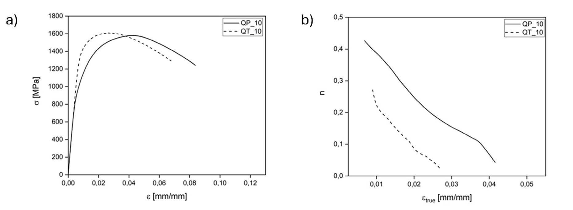
Fig.5 - Confronto tra le prove di trazione QT-QP per l'acciaio 30CrNiMo8 partizionato/temprato a 235 °C per 10 minuti. a) Prove di trazione, b) coefficienti di incrudimento istantaneo / QT-QP tensile tests comparison for 30CrNiMo8 steel partitioned/tempered at 235 °C, 10 minutes. a) Tensile tests, b) instantaneous hardening coefficients.
In Fig. 4a, comparative QT and QP samples for a 30CrNiMo8 steel are presented. The two conditions show a similar UTS, as expected by the presence of a same-tempered martensitic matrix. Yield strength is lower in the QP sample, leading to an increased UTS/YS ratio and improved work hardening. The comparative work-hardening behavior of QT and QP is highlighted in Fig. 4b. The trend of the instantaneous hardening coefficient “n” reflects the previous considerations as QP sample shows an increased initial value along straining, leading to an increased uniform elongation (UE). This behavior has been previously observed, and is due to the progressive deformation and transformation of austenite in martensite along straining, which enhances the hardening coefficient delaying the onset of necking [13][25] and so increases ductility and especially uniform elongation.
In addition to tensile properties, steel must guarantee
sufficient toughness before being put into service. In the presence of a crack, the material dissipates strain energy through plasticization at the crack tip or through crack propagation. The presence of soft RA in the microstructure is reported to enhance the fracture toughness of steels thanks to its ability to dissipate energy through deformation and strain-induced transformation [26][27]. Toughness can be a major issue for SS-QP treated material, as one of the limitations of the SS-QP treatment is the thin window of process parameters that can be exploited. The use of low temperatures for the treatment allows limited martensite tempering, which can lead to interesting tensile properties but an overall brittle behavior at fracture, even in presence of retained austenite. Some preliminary results are presented in Fig. 6. In Fig. 6a, Charpy samples show an improved toughness for QP samples. Fig. 6b shows the results of fracture toughness tests. In Fig. 6b, the comparison between QT and QP samples shows an improvement in toughness of the latter thanks to RA presence.
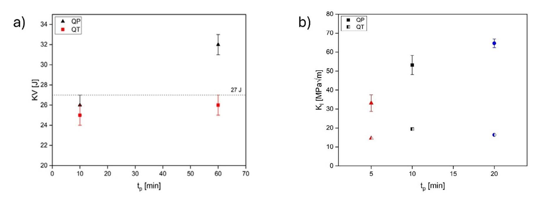
Fig.6 - Confronto tra i valori di resilienza e tenacità alla frattura QT/QP. a) Risultati Charpy KV per un acciaio 30CrNiMo8 partizionato/temprato a 235 °C, b) Risultati della tenacità alla frattura per l'acciaio AISI 4140 / Toughness values QT/QP comparison. a) Charpy V-Notch results for a 30CrNiMo8 steel tempered/partitioned at 235 °C, b) Fracture toughness results for AISI 4140 steel.
The results of different studies have shown the applicability of SS-QP on commercial steels. The selection of the chemical composition must guarantee the hardenability of the material through salt bath quenching, avoiding other phase transformations. Consequently, compositions such as C35 and 20MnB5 are identified as lower bound for the application of the treatment. Although commercial steels are characterized by a lower amount of Si-Mn compared to tailored QP compositions (Fig. 1) and they feature a reduced efficiency of the treatment due to uncontrolled carbide formation, RA fractions have been successfully stabilized in multiple low-alloyed steel grades. However, although RA contributes positively to ductility and toughness through the TRIP effect, its beneficial impact may not fully compensate for the brittleness of the lowtempered martensitic matrix — especially in SS-QP conditions where partitioning temperatures are limited. Therefore, the overall mechanical balance depends strongly on both RA stability and the extent of martensite tempering.
SS-QP treatments appear to be a promising solution
to achieve ultra-high tensile properties coupled with improved ductility compared to traditional treatments. The selection of the parameters for the heat treatment (Tq, tp) is crucial for achieving the desired final microstructure while avoiding undesired phase transformations, such as bainite and fresh martensite formation [28]. The combination of low quenching temperatures (15% austenite) and medium partitioning times (10-120 minutes) was identified as the most effective.
The computation of the tempering parameter T(C+log 10t) summarizes the time and temperature effect for different tempering treatments, which were individually optimized for the specific steel [29]. This tempering parameter allows for the comparison of different tempering/partitioning treatments and can be used to estimate the thermal energy required in the process; a higher value corresponds to a higher energy consumption (and thus energetic cost) during the treatment. The results summarized in Fig. 7 show the possibility of obtaining comparative YS between QP samples and traditional QT standards, suggesting potential for energy savings and improved ductility at equivalent strength levels.
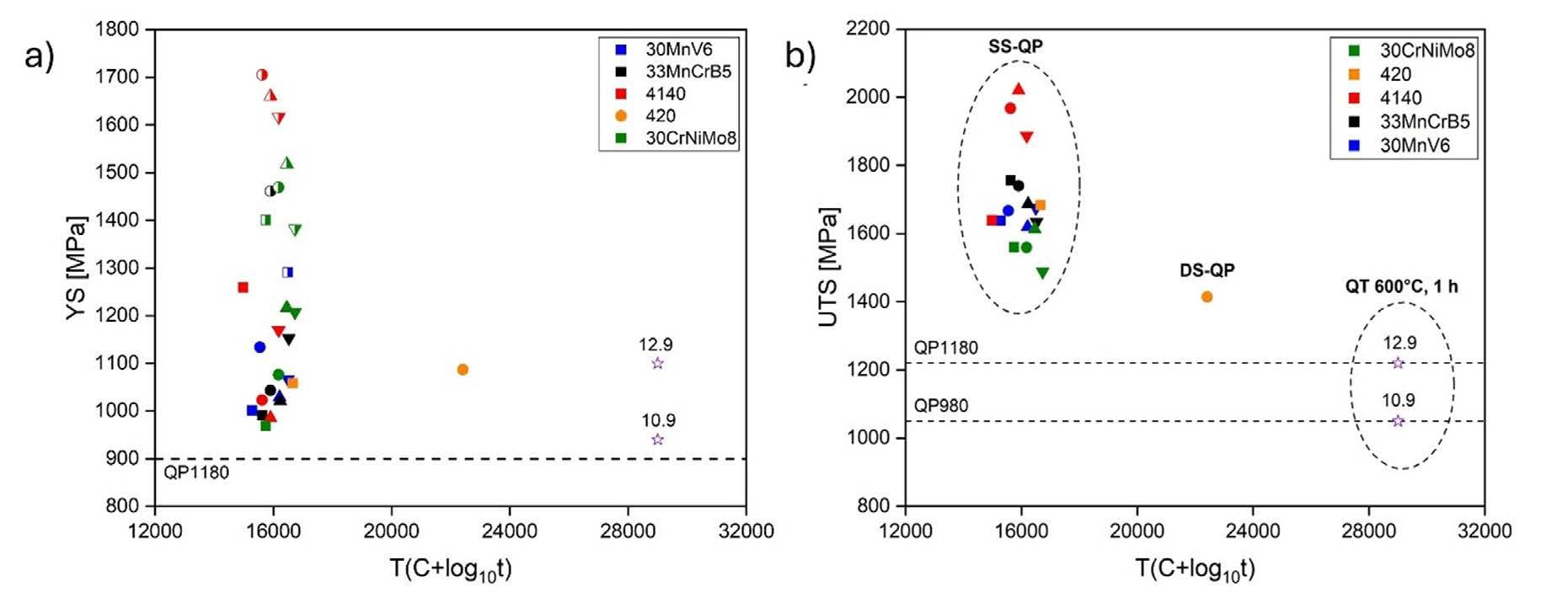
Fig.7 - Rappresentazione delle proprietà meccaniche ottenute con QP (e QT comparativi) in funzione del livello di rinvenimento equivalente. a) Carico di snervamento, b) Carico massimo / Representation of mechanical properties obtained with QP (and comparative QT) as a function of equivalent tempering level. a) Yield strength, b) UTS
Compared to their QT counterparts with the same martensite tempering, higher ductility and work-hardening coefficient are obtained in QP conditions, at the expense of decreased YS: these features are due to the progressive deformation and strain induced transformation of RA in martensite during straining. However, even though the presence of soft austenite in QP-treated materials increases the toughness of the material compared to QT conditions, the presence of a low-tempered martensite might lead to an overall brittle behavior which is not
acceptable in practical use. A correct combination of martensite tempering and austenite presence can lead to sufficient final toughness, with values similar to more traditional QT treatments (Fig. 6b). In the state of the art, this is one of the major limitations of SS-QP treatment. The variability in the choice of process parameters around the optimum with good results is limited: Tq (equal to Tp) can be neither too high nor too low, and the partitioning time has an upper limit set by industrial common sense and a lower limit due to issues of martensite brittleness. The maximum reachable austenite stability is ultimately low [30]. These constraints limit variability of results that can be obtained as to UTS and RA% from a single chemical composition. Consequently, even if the applicability of SS-QP treatment on commercial steels is assessed, the selection of the composition of the steel should be selected based on the requested final tensile properties taking into account the narrow operating window around the optimal heat treatment. The use of a DS-QP treatment could increase martensite tempering and austenite stabilization thanks to the higher Tp which can be selected independently of Tq, leading to a final material with lower UTS compared to SS-QP condition, but with overall improved toughness. However, the industrial implementation of a DS-QP treatment can be
complex due to the presence of two isothermal baths and the increase in the number of process parameters.
The analysis of the results of the application of SS-QP treatment on a pool of low-alloyed commercial steels was presented. Although the non-tailored composition sets some challenges for the success of the heat treatment and thus must be selected carefully, SS-QP applicability has been assessed on multiple steel grades. Microstructures composed of martensite and RA with ultra-high tensile properties (UTS > 1400 MPa) and improved ductility (reaching also 18%) and toughness were obtained. The selection of low partitioning temperature and medium partitioning times is the most effective for controlling the microstructure. Nevertheless, the main limitation of the treatment is the limited range of effective process parameters around the optimum (especially Tp) for a successful result. The low partitioning temperatures restrict the tempering of the martensitic matrix and carbon diffusion; consequently, even if improved, ductility and toughness remain limited. In conclusion, SS-QP appears to be a promising heat treatment for specific ultra-highstrength applications that require increased ductility and work hardening.
[1] J SPEER, DK MATLOCK, BC DE COOMAN, JG SCHROTH, Carbon partitioning into austenite after martensite transformation, Acta Mater. (2003).
[2] S KUMAR, SB SINGH, Quenching and Partitioning (Q&P) Steel: Alloy Design, Phase Transformation and Evolution of Microstructure, Metall Mater Trans A Phys Metall Mater Sci. (2023).
[3] M SOLEIMANI, A KALHOR, H MIRZADEH, Transformation-induced plasticity (TRIP) in advanced steels: A review, Mater Sci Eng A. (2020).
[4] E DE MOOR, JG SPEER, DK MATLOCK, DN HANLON, Effect of retained austenite on tensile behavior of AHSS revisited, Mater Sci Technol Conf Exhib 2011, MS T’11. (2011).
[5] I MIETTUNEN, S GHOSH, MC SOMANI, S PALLASPURO, J KÖMI, Competitive mechanisms occurring during quenching and partitioning of three silicon variants of 0.4 wt.% carbon steels, J Mater Res Technol. (2021).
[6] S BARELLA, M BELFI, A GRUTTADAURIA, P CETTO, C LIU, Y PENG, Influence of Quenching and Partitioning on the Mechanical Properties of Low-Silicon 33MnCrB5 Boron Steel, Steel Res Int. (2023).
[7] S BARELLA, M BELFI, A GRUTTADAURIA, C LIU, Y PENG, Metallurgical and Mechanical Investigation on Single-Step Quenching and Partitioning Thermal Treatments on Commercial Low Alloyed 30MnV6 Steel, Metall Mater Trans A Phys Metall Mater Sci. (2023).
[8] V KURUP, C SIYAYISA, R MOSTERT, J MOEMA, Study of one-step and two-step quench and partition heat treatments on a medium carbon high silicon alloy using dilatometry, Suid-Afrikaanse Tydskr vir Natuurwetenskap en Tegnol. (2022).
[9] S KAAR, D KRIZAN, R SCHNEIDER, C SOMMITSCH, Impact of Si and Al on Microstructural Evolution and Mechanical Properties of Lean Medium Manganese Quenching and Partitioning Steels, Steel Res Int. (2020).
[10] CB FINFROCK, MM THRUN, D BHATTACHARYA, TJ BALLARD, AJ CLARKE, KD CLARKE, Strain Rate Dependent Ductility and Strain Hardening in Q&P Steels, Metall Mater Trans A Phys Metall Mater Sci. (2021).
[11] Y TOJI, G MIYAMOTO, D RAABE, Carbon partitioning during quenching and partitioning heat treatment accompanied by carbide precipitation, Acta Mater. (2015).
[12] J HIDALGO, KO FINDLEY, MJ SANTOFIMIA, Thermal and mechanical stability of retained austenite surrounded by martensite with different degrees of tempering, Mater Sci Eng A. (2017).
[13] KO FINDLEY, J HIDALGO, RM HUIZENGA, MJ SANTOFIMIA, Controlling the work hardening of martensite to increase the strength/ ductility balance in quenched and partitioned steels, Mater Des. (2017).
[14] AJ CLARKE, JG SPEER, MK MILLER, RE HACKENBERG, D V. EDMONDS, DK MATLOCK, ET AL., Carbon partitioning to austenite from martensite or bainite during the quench and partition (Q&P) process: A critical assessment, Acta Mater. (2008).
[15] MJ SANTOFIMIA, L ZHAO, R PETROV, J SIETSMA, Characterization of the microstructure obtained by the quenching and partitioning process in a low-carbon steel, Mater Charact. (2008).
[16] D DE KNIJF, R PETROV, C FÖJER, LAI KESTENS, Effect of fresh martensite on the stability of retained austenite in quenching and partitioning steel, Mater Sci Eng A. (2014).
[17] H JIRKOVÁ, L KUČEROVÁ, B MAŠEK, Effect of quenching and partitioning temperatures in the Q-P process on the properties of AHSS with various amounts of manganese and silicon, Mater Sci Forum. (2012).
[18] SYP ALLAIN, S AOUED, A QUINTIN-POULON, M GOUNÉ, F DANOIX, JC HELL, ET AL., In situ investigation of the iron carbide precipitation process in a Fe-C-Mn-Si Q & P steel, Materials (Basel). (2018).
[19] A ARLAZAROV, M OLLAT, JP MASSE, M BOUZAT, Influence of partitioning on mechanical behavior of Q&P steels, Mater Sci Eng A. (2016).
[20] S EBNER, R SCHNITZER, E MAAWAD, C SUPPAN, C HOFER, Influence of partitioning parameters on the mechanical stability of austenite in a Q&P steel: A comparative in-situ study, Materialia. (2021).
[21] C CELADA-CASERO, C KWAKERNAAK, J SIETSMA, MJ SANTOFIMIA, The influence of the austenite grain size on the microstructural development during quenching and partitioning processing of a low-carbon steel, Mater Des. (2019).
[22] F HAJYAKBARY, J SIETSMA, G MIYAMOTO, T FURUHARA, MJ SANTOFIMIA, Interaction of carbon partitioning, carbide precipitation and bainite formation during the Q&P process in a low C steel, Acta Mater. (2016).
[23] S DHARA, SMC VAN BOHEMEN, MJ SANTOFIMIA, Isothermal decomposition of austenite in presence of martensite in advanced high strength steels: A review, Mater Today Commun. (2022).
[24] M CARPIO, J CALVO, O GARCÍA, JP PEDRAZA, JM CABRERA, Heat treatment design for a qp steel: Effect of partitioning temperature, Metals (Basel). (2021).
[25] E DE MOOR, S LACROIX, AJ CLARKE, J PENNING, JG SPEER, Effect of retained austenite stabilized via quench and partitioning on the strain hardening of martensitic steels, Metall Mater Trans A Phys Metall Mater Sci. (2008).
[26] I DE DIEGO-CALDERÓN, I SABIROV, JM MOLINA-ALDAREGUIA, C FÖJER, R THIESSEN, RH PETROV, Microstructural design in quenched and partitioned (Q&P) steels to improve their fracture properties, Mater Sci Eng A. (2016).
[27] CB FINFROCK, B ELLYSON, SRJ LIKITH, D SMITH, CJ RIETEMA, AI SAVILLE, ET AL., Elucidating the temperature dependence of TRIP in Q&P steels using synchrotron X-Ray diffraction, constituent phase properties, and strain-based kinetics models, Acta Mater. (2022).
[28] M BELFI, M MARIANI, P MARTIN, M SANTOFIMIA, A GRUTTADAURIA, F DEIRMINA, ET AL., Microstructural development via synergic application of binder jetting and quenching and partitioning (QP) on commercial AISI 4340, Mater Charact. (2025).
[29] LCF CANALE, X YAO, J GU, GE TOTTEN, A historical overview of steel tempering parameters, Int J Microstruct Mater Prop. (2008).
[30] S EBNER, R SCHNITZER, E MAAWAD, C SUPPAN, C HOFER, Influence of partitioning parameters on the mechanical stability of austenite in a Q&P steel: A comparative in-situ study, Materialia. (2021).
Il Quenching and Partitioning (QP) è un trattamento termico per acciai ad alta resistenza che permette di avere, a temperatura ambiente, una microstruttura formata da martensite e austenite residua. La presenza di queste fasi conferisce una combinazione di resistenza meccanica e duttilità che è difficilmente ottenibile con trattamenti tradizionali. Questo trattamento è generalmente applicato ad acciai con specifiche composizioni chimiche (acciai QP), caratterizzate da un’elevata presenza di silicio e manganese, che favoriscono l’efficacia del trattamento. Tuttavia, queste composizioni sono lontane da quelle abitualmente prodotte a livello industriale. Il presente studio analizza l’applicabilità del QP su diversi acciai commerciali ad alta resistenza, le cui composizioni chimiche non sono studiate appositamente per questo trattamento, ma sono comunemente già in produzione. Sono presentati criteri per la scelta del materiale e dei parametri di processo, e sono analizzate le caratteristiche microstrutturali e le proprietà meccaniche finali. L’obiettivo dello studio è di fornire, a partire dai risultati di ricerche precedenti, delle linee guida per l’applicazione del QP su acciai commerciali, indicandone limitazioni e possibilità.
A. Ferrarotti, A. Difalco, F. Giuffrida, G. Mussino, M. Vedani, M. Baricco, A. Castellero
Questo lavoro di ricerca è rivolto allo studio dell’effetto del trattamento termico sulla microstruttura e sulle proprietà meccaniche della superlega Inconel 718 (IN718) prodotta tramite manifattura additiva, utilizzando la tecnica di fusione laser a letto di polvere (L-PBF). Per studiare le proprietà sopra menzionate dei campioni, sono state impiegate varie tecniche, tra cui la microscopia ottica, la microscopia elettronica a scansione, la diffrazione di elettroni retrodiffusi, le misurazioni di durezza Vickers e i test di compressione. Il trattamento termico impiegato consiste nella procedura standard per la lega IN718 e comprende una solubilizzazione a 980 °C per 1 ora, quindi una tempra in acqua, seguita da un primo invecchiamento a 720 °C per 8 ore, un raffreddamento di due ore fino a 620° e raggiunta tale temperatura un secondo invecchiamento per 8 ore. La microstruttura risultante mostra all’interno dei grani alcuni precipitati fini di tipo γ’/γ’’ dispersi nella matrice γ, mentre lungo i bordi di grano si individua una distribuzione continua di precipitati più grossolani, attribuibili sia alla fase δ che alla fase di Laves. I risultati delle prove di compressione, eseguite su strutture reticolari, evidenziano un infragilimento complessivo dovuto alla presenza delle fasi sopra citate. In prospettiva, è necessario ottimizzare il trattamento termico al fine di evitare o ridurre la formazione delle fasi infragilenti.
PAROLE CHIAVE: ADDITIVE MANUFACTURING, IN718, STRUTTURE RETICOLARI, TRATTAMENTI TERMICI ;
La tecnologia di Additive Manufacturing (AM) di polveri metalliche, sviluppata negli ultimi trent’anni come tecnica di prototipazione rapida, è recentemente cresciuta in modo significativo e ad oggi è ampiamente utilizzata per i suoi vantaggi in termini di costi e di riduzione di materiale di scarto. Lo sviluppo delle diverse tecniche di manifattura additiva in campo metallurgico ha trovato applicazione principalmente nei settori biomedicale, manifatturiero, automotive e aerospaziale, grazie anche alla possibilità di realizzare manufatti ad elevata complessità geometrica, senza compromessi imposti dalle limitazioni dei processi convenzionali [1-4]. L’AM è spesso considerato una colonna portante dell’Industria 4.0, che mira alla produzione in-situ di prodotti estremamente orientati alle specifiche esigenze dei clienti. La fusione laser a letto di polvere (L-PBF) è una delle tecniche AM più utilizzate per la realizzazione di componenti metallici. Il processo parte dalla costruzione di un modello CAD, quindi segue il suo orientamento all'interno di un volume di costruzione per
A. Ferrarotti, A. Difalco, M. Baricco, A. Castellero
Dipartimento di Chimica e NIS – INSTM, Università degli Studi di Torino, Torino
F. Giuffrida, G. Mussino CIM 4.0, Competence Industry Manufacturing Centre, Torino
M. Vedani
Dipartimento di Ingegneria meccanica, Politecnico di Milano, Milano
includere le strutture di supporto, la successiva suddivisione in layer, la definizione di una strategia di scansione e di una serie di parametri specifici dei materiali impiegati. L’oggetto viene realizzato depositando sottili strati di polvere e fondendoli progressivamente, attraverso un sistema di controllo digitale, all'interno di una camera in atmosfera inerte [1,5]. In questo processo, l’elevata velocità di raffreddamento induce un forte gradiente termico, ciò influenza sia la morfologia della microstruttura (dendritiche planari, cellulari, colonnari o equiassiche), sia le proprietà meccaniche [6,7].
Considerando le diverse tecniche di AM, la ricerca metallurgica è principalmente indirizzata verso due direzioni. In primo luogo, l’ottimizzazione delle proprietà microstrutturali e meccaniche dei manufatti, che è essenziale per garantire semilavorati o prodotti finiti che soddisfino le qualifiche e i requisiti previsti dalle normative. L’ottimizzazione del processo di stampaggio, e delle tecniche di post-processing richiede un’intima comprensione delle relazioni tra le proprietà microscopiche (microstruttura, forma e dimensione dei grani, porosità, termodinamica e cinetica di solidificazione) e macroscopiche (durezza, resistenza a snervamento e a frattura, tenacità, ecc.). Di particolare rilevanza è lo studio delle microstrutture derivanti dalla rapida solidificazione, tipica delle tecniche AM, e della rugosità superficiale dei manufatti stampati, la quale è critica per prevenire cedimenti dovuti a fratture da fatica. In secondo luogo, lo studio delle tecniche di atomizzazione di polveri metalliche è essenziale per ampliare il quadro di leghe processabili per AM. Infatti, a causa della peculiare modalità con cui il letto di polveri metalliche viene steso e movimentato, una granulometria fine e una forma quasi perfettamente sferica risultano requisiti fondamentali per il corretto svolgimento del processo. I progressi in questo filone di ricerca hanno permesso di ampliare la gamma di leghe utilizzabili, partendo da un iniziale ristretto gruppo di leghe a base alluminio, fino all’attuale ampia varietà, composta da superleghe a base Ni, acciaio maraging, e leghe a base Ti e Cu, allargando considerevolmente i settori di applicabilità.
Le superleghe a base Ni vengono utilizzate laddove siano richieste elevate sollecitazioni (ad esempio trazione, fatica, tenacità e termiche) in combinazione ad una buona resistenza alla corrosione o all'ossidazione. Di conseguenza, hanno trovato largo impiego nei motori a combustione
ad alte prestazioni (turbine a gas in ambito aerospaziale) e per la produzione di energia in centrali termoelettriche, ma anche nucleari (rotori, dischi di turbine, pale, alberi, cuscinetti, mandrini e bulloni). Inconel 718 (IN718) è una superlega a base Ni specificatamente progettata per applicazioni ad alte temperature. Tale lega può tollerare temperature di servizio fino a 1050 °C, con esposizioni occasionali fino a 1200 °C, vicino alla regione del punto di fusione del materiale (l'intervallo di solidificazione è 1260-1336 °C) [8]. Si basa sul sistema ternario Ni-Cr-Fe, composto da una matrice austenitica FCC γ indurita tramite precipitazione di fasi rinforzanti, tra cui γ′ FCC con stechiometria Ni3(Al,Ti) e BCT γ″ identificata come Ni3Nb. IN718, inoltre, è una lega ampiamente utilizzata per la fabbricazione di strutture reticolari [9-14]. Secondo la definizione di Gibson, le strutture reticolari sono “materiali cellulari costituiti da una rete interconnessa di aste e nodi” [15]. Sono generate dalla ripetizione di celle unitarie fino a formare l'intera struttura e possono essere classificate in due differenti categorie a seconda della risposta meccanica al carico applicato. La prima categoria include le strutture bending-dominated, che subiscono principalmente momenti flettenti all'interno della loro struttura, la seconda invece riguarda le strutture stretch-dominated, che subiscono principalmente carichi assiali, essendo rigide e resistenti. Pertanto, il comportamento meccanico di una struttura reticolare dipende in primo luogo dalla distribuzione del carico, ma anche dal materiale costituente, dalla sua architettura e dalla sua porosità rispetto al materiale pieno [16].
Lo scopo di questo lavoro è di studiare l’effetto sulle proprietà microstrutturali e meccaniche del trattamento termico standard su strutture reticolari in IN718. Tale trattamento, consistente in un solution annealing a 980 °C per 1 h seguito da un doppio invecchiamento a 720 °C (8 h) e 620 °C (8h), è il trattamento standard, utilizzato su manufatti realizzati in IN718 per mezzo di tecniche di produzione tradizionali, come il casting. Su manufatti prodotti per AM, la sequenza di trattamento, in termini di temperature e tempi, è tuttora oggetto di dibattito [17]. Se da un lato l’effetto macroscopico di infragilimento e di aumento della durezza è ben documentato, le cause microscopiche di tali comportamenti non sono del tutto state chiarite. Essendo la precipitazione di fasi infragilenti a bordo grano critica nel determinare le proprietà meccaniche finali, lo
studio microstrutturale e metallografico ricopre un ruolo importante. Lo studio è stato condotto parallelamente sia sul materiale bulk, sia sulle strutture reticolari mediante le seguenti tecniche: microscopia ottica ed elettronica, diffrazione di elettroni retrodiffusi, durezza Vickers e prove di compressione. I risultati ottenuti hanno mostrato la necessità di ottimizzare il trattamento termico.
MATERIALI E METODI
I campioni indagati sono stati fabbricati a partire da polveri commerciali atomizzate, prodotte da EOS GmbH e realizzati per manifattura additiva utilizzando una macchina Print Genius 250 L-PBF di Prima Additive, dotata di due laser a itterbio IR monomodale da 500 W, in un’atmosfera inerte di argon. Il job di stampa ha previsto la produzione di cubi di 13 mm di lato (denominati campioni bulk) e di strutture reticolari, con tre diverse geometrie. La geometria A ha una struttura cosiddetta diamante, la struttura B ha una cella BCC a nodi arrotondati e la struttura C presenta una struttura dodecaedrica rombica. I campioni sono stati sezionati sia lungo il piano orizzontale (xy), cioè parallelo alla piattaforma di costruzione, sia lungo il piano verticale (xz), cioè lungo la direzione di costruzione (Z). I campioni sono stati sottoposti a trattamento termico standard previsto da scheda tecnica suddiviso in due step: solution annealing a 980 °C per 1 h seguito da invecchiamento in due fasi, primo invecchiamento a 720 °C per 8 h, raffreddamento controllato in 2h e secondo invecchiamento a 620 °C per 8 h.
Per l’analisi microstrutturale, i campioni sono stati lucidati fino a 40 nm con soluzione di silice abrasiva e poi attaccati con la soluzione di Kalling n°2 (miscela CuCl2 e
HCl:CH3CH2OH 1:1) per tempi di attacco variabili. Le analisi sono state effettuate mediante microscopia ottica (OM), con un microscopio Leica DFC295, e microscopia elettronica a scansione (SEM), con un TESCAN VEGA 4, sia con elettroni secondari che retrodiffusi. L'analisi EBSD è stata effettuata utilizzando un TESCAN S9000 FESEM con una sonda EBSD Symmetry S3 di Oxford Instruments, mentre la successiva elaborazione dei dati è stata eseguita mediante il software Aztec Crystal.
Le proprietà meccaniche di compressione sono state valutate con una macchina elettromeccanica Alliance, fino ad un carico massimo di 150 kN, dotata di estensimetro per il monitoraggio delle deformazioni e corretto per la deformazione intrinseca della traversa. Le misurazioni di durezza con microindentazione sono state effettuate utilizzando un Buehler 1600-6105 con carico applicato di 500 gf.
RISULTATI E DISCUSSIONE
In Fig. 1 sono riportate le micrografie ottiche relative al campione bulk. A sinistra, Fig. 1 (a), il campione è stato analizzato lungo il piano xy, lungo cui risultano evidenti ancora le tracce regolari dovute alla fusione del laser, corrispondenti ai pozzetti di fusione, dovuti al processo produttivo. Questi sono allineati seguendo le direzioni definite dalla strategia di scansione. Lungo il piano xz, Fig. 1 (b), i pozzetti sono visibili sotto forma di una serie di archi, indotti da effetti di dispersione del calore, tipici della tecnica di AM, dalla zona superficiale del fuso agli strati precedentemente solidificati. I risultati dell’analisi microstrutturale sulle strutture lattice sono assimilabili a quelli ottenuti per il campione bulk.
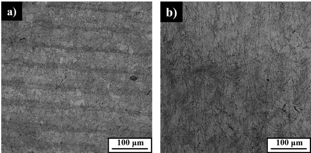
Fig.1 - Micrografie ottiche dei campioni bulk di IN718 lungo i piani xy e xz / Optical micrographs of IN718 bulk samples along xy and xz sides.
Successivamente è stata utilizzata la tecnica EBSD per evidenziare la forma dei grani e l’eventuale presenza di
orientazioni preferenziali, come mostrato in Fig. 2.

Fig.2 - Mappe EBSD di campioni bulk di IN718 lungo l'asse z, che corrisponde alla direzione di costruzione, per il piano xy (a) e per il piano xz (b). In (c) una mappa a più elevati ingrandimenti evidenzia la presenza di fasi infragilenti / EBSD maps of IN718 bulk samples along the z-axis, which corresponds to the building direction, for xy side (a) and for the xz side (b). In (c) a higher magnification map highlighting the presence of brittle phases.
I grani appaiono approssimativamente equiassici lungo il piano xy, Fig. 2 (a), mentre lungo il piano xz, Fig. 2 (b), mostrano una forma più allungata, derivante dalla crescita colonnare lungo la direzione z, causata dal flusso termico verticale dovuto al trasferimento di calore verso gli strati già depositati e il substrato. Inoltre, come si può notare in entrambe le immagini, è ancora visibile la forma delle tracce di fusione, descritte nella sezione precedente riportante le micrografie ottiche. Inoltre non si evidenzia la presenza di orientazioni preferenziali, al contrario di quanto osservato nei campioni as built, il che risulta ragionevole in quanto a seguito del trattamento termico si ha una generale omogenizzazione [16]. In Fig. 2 (c) è stata
riportata una mappa ad ingrandimenti maggiori per mettere in evidenza la presenza delle fasi secondarie δ e Laves distribuite a bordo grano.
Andando ad ingrandimenti maggiori è stato possibile confermare la forma dei grani, più equiassica lungo il piano xy, Fig. 3 (a), più allungata lungo il piano xz, Fig. 3 (b) coincidente con la direzione di costruzione in macchina. In Fig. 3 sono riportate le micrografie SEM relative al campione bulk, e si può notare la presenza di precipitati di natura più o meno grossolana, attribuibili alle fasi secondarie rafforzanti. In Fig. 3 (c), acquisita ad ingrandimenti più elevati, è visibile chiaramente che all’interno dei grani sono
dispersi alcuni precipitati più fini γ’/γ’’ nella matrice scura γ, mentre lungo i bordi di grano sono distribuiti in modo
continuo precipitati più grossolani attribuibili alla fase δ e fase Laves.
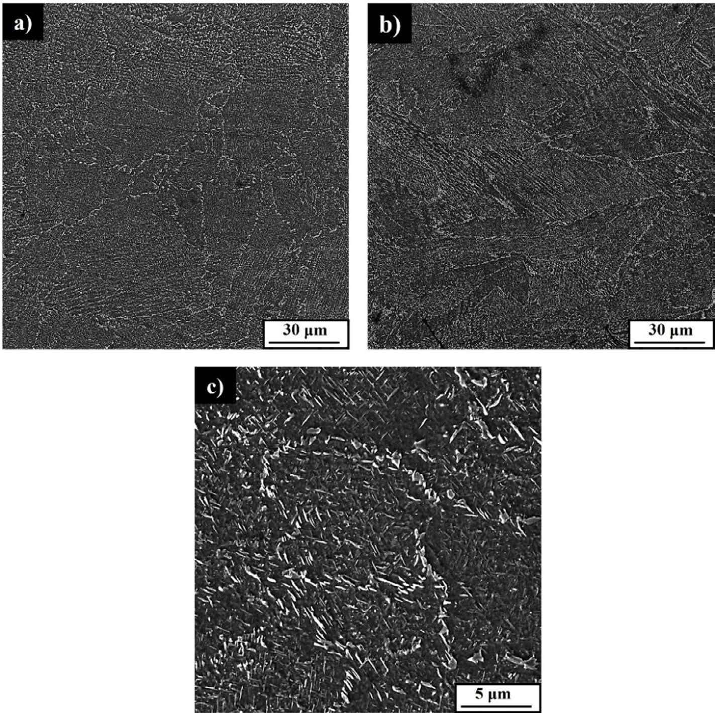
Fig.3 - Micrografie SEM dei campioni bulk di IN718 lungo il piano xy (a,c) e xz (b) a diversi ingrandimenti / SEM micrographs of IN718 bulk samples along xy side (a, c) and xz side (b) at different magnifications.
L’analisi meccanica dei campioni è partita dall’analisi delle curve sforzo deformazione, Fig. 4 grafico a destra, ricavate dai test di compressione effettuati sulle strutture reticolari. Tutti i test sono stati eseguiti fino al carico massimo della macchina, ovvero 150 kN. Dall'andamento del tratto elastico delle curve, sono stati ottenuti i valori di modulo elastico di 97.5, 188.8 e 105.4 GPa, rispettivamente per le strutture A, B e C, mentre i valori relativi al carico di snervamento σ0.2 sono 135.4 e 253.1 MPa per le strutture A e B, rispettivamente. Per la struttura C non è stato possibile ricavarlo, in quanto raggiunto il carico massimo della macchina, non si è indotto lo snervamento. Dopo aver raggiunto il carico massimo consentito della macchina, la struttura A ha mostrato una deformazione
massima (εmax) del 43 %, la struttura B del 23 % e C del 2 %. Inoltre, secondo la classificazione di Gibson-Ashby, le strutture considerate presentano un comportamento di tipo bending-dominated, evidenziando, nel tratto elastico, un plateau con piccole fluttuazioni, attribuibili alla rottura di alcune aste all’interno della struttura. In Tab. 1 sono stati riportati, per confronto, i valori ottenuti dalle prove meccaniche sulle strutture reticolari prima e dopo il trattamento termico [16].
Tab.1 - Confronto valori di modulo elastico, carico di snervamento e deformazione (a carico massimo) per strutture reticolari prima e dopo il trattamento termico / Comparison of elastic moduli, yield strength and deformation values (at maximum load) for lattice structures before and after the heat treatment.
Struttura A
As-buit
Struttura B
Struttura C
La durezza Vickers, riportata nel grafico a sinistra in Fig. 4, è stata misurata lungo i piani xy e xz, sia su campioni bulk che sulle strutture reticolari. Per i campioni bulk, sè stato trovato un valore medio di 537 ± 5 HV e 478 ± 5 HV, rispettivamente lungo xy e xz. Per le strutture reticolari, la durezza è stata misurata sia sui nodi che sulle aste, tut-
tavia, non sono state riscontrate differenze significative, pertanto, è stato solo riportato un valore mediodi 535 +_ 15 HV, 539+_10 HV e 531 +_ 12 HV, rispettivamente per le strutture reticolari A, B e C.. Come risulta evidente, rispetto ai campioni as-built, a seguito del trattamento termico si ha un notevole incremento nei valori di durezza [16].
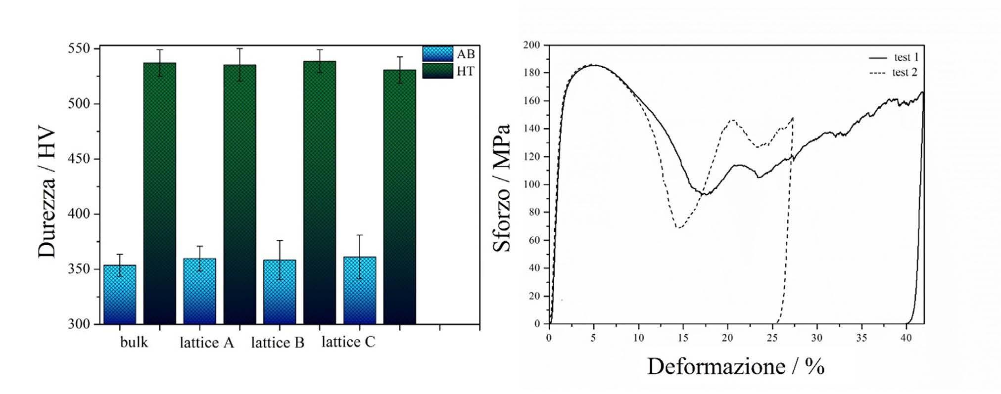
Fig.4 - A sinistra i valori di durezza Vickers ottenuti per campioni bulk e strutture reticolari prima (blu) e dopo (verde) trattamento termico, a destra la curva sforzo-deformazione della struttura reticolare A trattata termicamente / On the left Vickers hardness values obtained for bulk and lattice structures before (blue) and after (green) heat treatment, on the right stress-strain curve of heat treated lattice structure A.
Infine, a seguito delle prove di compressione, la struttura reticolare A è arrivata a frattura, pertanto su di essa è stata successivamente effettuata un’analisi frattografica mediante l’acquisizione di immagini SEM. In Fig. 5 sono mostrate alcune micrografie che presentano la superficie di frattura. Essa è caratterizzata da elementi sia di tipo fra-
gile che di tipo duttile. Le possibili cause di infragilimento, con conseguente rottura avvenuta nella struttura reticolare A trattata termicamente, sono principalmente l’aumento della porosità e la presenza diffusa di fasi infragilenti distribuite a bordo grano, come evidenziato in Fig. 2 (c).
Fig.5 - Analisi frattografica della struttura reticolare A, osservata mediante SEM a seguito delle prove di compressione (a) e (b) e una micrografia ottica (c), che evidenzia la diffusa presenza di pori. / Fractography of lattice A, seen at the SEM (a) and (b) after compression tests and an optical micrograph (c) showing the large presence of pores.
Al termine della caratterizzazione sul campione trattato termicamente secondo trattamento standard, è stato possibile concludere che, sia dal punto di vista microscopico che meccanico, il trattamento non abbia evidenziato l’incremento in termini di performance atteso, causando un eccessivo infragilimento delle strutture. Dopo una valutazione dei risultati sono al momento in corso modifiche del trattamento termico, partendo da un’analisi step-bystep della sequenza con particolare attenzione allo stadio di solubilizzazione.
CONCLUSIONI
Lo studio è stato rivolto alla caratterizzazione di campioni bulk e di strutture reticolari di IN718 prodotti per manifattura additiva presso CIM4.0 e trattati termicamente, secondo trattamento termico standard. A seguito di tale trattamento, è risultato evidente che, dal punto di vista microstrutturale, i campioni presentassero ancora, a bas-
si ingrandimenti, una traccia dei pozzetti di fusione, tipici della tecnica additiva, mentre a più alti ingrandimenti hanno rivelato la presenza, all’interno dei grani di matrice γ, di alcuni precipitati fini, attribuibili a γ’/γ’’. Lungo i bordi di grano sono, invece, distribuiti in modo continuo precipitati più grossolani che, dalle analisi EBSD ad elevato ingrandimento, sono stati assegnati alle fasi δ e Laves. Dalle mappe EBSD a più basso ingrandimento è stato possibile individuare la forma dei grani, equiassici lungo il piano xy e colonnari, con forma allungata lungo la direzione di crescita, lungo il piano xz. Dalle misure di durezza Vickers è risultato che i valori medi di durezza siano tutti confrontabili tra loro. Inoltre, rispetto al campione non trattato termicamente, i valori di durezza risultano superiori e con una deviazione standard inferiore, suggerendo un’omogeneizzazione derivante dal trattamento termico ma anche un infragilimento, essendo tale aumento di durezza associato ad una riduzione della deformazione a frattura.
Infine, per quanto riguarda le prove di compressione delle strutture reticolari, le curve sforzo-deformazione hanno rivelato per tutte le strutture un comportamento di tipo bending-dominated, con alcune fluttuazioni in campo plastico assegnate alla frattura di aste interne alle strutture. Rispetto ai valori di modulo elastico delle strutture reticolari as-built, per i campioni trattati termicamente, il modulo elastico è lievemente più alto, sebbene la deformazione a frattura presenti valori inferiori. Tale infragilimento è stato attribuito alla diffusa presenza di pori, ma soprattutto alla distribuzione di precipitati grossonali di fasi δ e Laves lungo i bordi dei grani, che risultano dannosi in termini di performance complessiva delle strutture.
In prospettiva, al fine di evitare l’infragilimento delle strutture, è necessario ottimizzare il trattamento termico. In particolare, è in corso un’analisi sistematica dell’effetto della temperatura di solubilizzazione sulla formazione delle fasi infragilenti durante il primo stadio del trattamento termico.
Gli autori ringraziano per il supporto il Progetto CH4.0, nell'ambito del programma MUR "Dipartimenti di Eccellenza 2023-2027" (CUP: D13C22003520001).
[1] T. DebRoy, H.L. Wei, J.S. Zuback, T. Mukherjee, J.W. Elmer, J.O. Milewski, A.M. Beese, A. Wilson-Heid, A. De, W. Zhang, Additive manufacturing of metallic components – Process, structure and properties, Prog Mater Sci 92 (2018) 112–224. https://doi. org/10.1016/j.pmatsci.2017.10.001.
[2] K. V Wong, A. Hernandez, A review of additive manufacturing, Int Sch Res Notices 2012 (2012) 1-10. https://doi.org/10.5402/2012/208760
[3] I. Gibson, D.W. Rosen, B. Stucker, M. Khorasani, D. Rosen, B. Stucker, M. Khorasani, Additive manufacturing technologies, Springer, 2021, pp. 160-186.
[4] W.E. Frazier, Metal additive manufacturing: a review, J Mater Eng Perform 23 (2014) 1917–1928. https://doi.org/10.1007/s11665-0140958-z.
[5] R. Acharya, J.A. Sharon, A. Staroselsky, Prediction of microstructure in laser powder bed fusion process, Acta Mater 124 (2017) 360–371. https://doi.org/10.1016/j.actamat.2016.11.018.
[6] W. Kurz, B. Giovanola, R. Trivedi, Theory of microstructural development during rapid solidification, Acta metallurgica 34.5 (1986) 823-830. https://doi.org/10.1016/0001-6160(86)90056-8.
[7] L.A. Jacobson, J. Mckittrick, A Review Journal Rapid solidification processing, Materials Science and Engineering: R: Reports 11.8 (1994) 355-408. https://doi.org/10.1016/0927-796X(94)90022-1
[8] S.K. Selvaraj, G. Sundaramali, S. Jithin Dev, R. Srii Swathish, R. Karthikeyan, K.E. Vijay Vishaal, V. Paramasivam, Recent advancements in the field of Ni-based superalloys, Advances in Materials Science and Engineering 2021 (2021) 1–60. https://doi. org/10.1155/2021/9723450
[9] A. Mostafaei, R. Ghiaasiaan, I.-T. Ho, S. Strayer, K.-C. Chang, N. Shamsaei, S. Shao, S. Paul, A.-C. Yeh, S. Tin, others, Additive Manufacturing of Nickel-based superalloys: a state-of-the-art review on process-structure-defect-property relationship, Prog Mater Sci 136 (2023) 101108. https://doi.org/10.1016/j.pmatsci.2023.101108
[10] X. Wang, X. Gong, K. Chou, Review on powder-bed laser additive manufacturing of Inconel 718 parts, Proc Inst Mech Eng B J Eng Manuf 231 (2017) 1890–1903. https://doi.org/10.1177/0954405415619883
[11] Q. Jia, D. Gu, Selective laser melting additive manufacturing of Inconel 718 superalloy parts: Densification, microstructure and properties, J Alloys Compd 585 (2014) 713–721. http://doi.org/10.1016/j.jallcom.2013.09.171.
[12] K. Georgilas, R.H.U. Khan, M.E. Kartal, The influence of pulsed laser powder bed fusion process parameters on Inconel 718 material properties, Materials Science and Engineering: A 769 (2020) 138527. http://doi.org/10.1016/j.msea.2019.138527
[13] P.I. Pradeep, V.A. Kumar, T. Venkateswaran, S. Aswin, V.S. Nair, A. Krishnan, Akhil, M. Agilan, S.K. Singh, P.R. Narayanan, Processing and Characterization of 3D-Printed Inconel-718 Component through Laser Powder Bed Fusion Route for High-Temperature Space Application, Transactions of the Indian National Academy of Engineering 6 (2021) 133–146. http://doi.org/10.1007/s41403-02000196-6
[14] B. Farhang, B.B. Ravichander, J. Ma, A. Amerinatanzi, N.S. Moghaddam, The evolution of microstructure and composition homogeneity induced by borders in laser powder bed fused Inconel 718 parts, J Alloys Compd 898 (2022) 162787. http://doi. org/10.1016/j.jallcom.2021.162787
[15] L.J. Gibson, M.F. Ashby, Introduction, in: Cellular Solids, Cambridge University Press, 2014, pp. 1–14. https://doi.org/10.1017/ cbo9781139878326.003.
[16] A. Ferrarotti, F. Giuffrida, E. Sharghivand, G. Mussino, M. Vedani, M. Baricco, A. Castellero, Mechanical and microstructural properties of IN718 additively manufactured lattice structures, Materials Science and Engineering: A, 919, 147491 (2025). https://doi. org/10.1016/j.msea.2024.147491
[17] E. Chlebus, K. Gruber, B. Kuźnicka, J. Kurzac, T. Kurzynowski, Effect of heat treatment on the microstructure and mechanical properties of Inconel 718 processed by selective laser melting, Materials Science and Engineering: A, 639, 647-655 (2015). https:// doi.org/10.1016/j.msea.2015.05.035.
This research work investigated the effect of the standard heat treatment for IN718 alloy on microstructure and mechanical properties of additively manufactured samples, fabricated using laser powder bed fusion technique (L-PBF). In order to investigate the above-mentioned properties of the specimens, many experimental techniques have been employed, namely optical microscopy, scanning electron microscopy, electron backscattered diffraction, Vickers hardness measurements and compression tests.
The investigated thermal treatment started from the standard industrial treatment usually performed on IN718 products. It includes a solution annealing at 980 °C for 1h then water quenching, followed by a first ageing at 720 °C for 8h, a controlled cooling for 2 h down to 620°, and then once this temperature is reached a second ageing for 8h. The resulting microstructure shows inside the grains, some fine γ’/ γ’’ precipitates dispersed in the γ matrix, while along the grain boundaries coarser precipitates were continuously distributed, attributable to both δ and Laves phases. The results of the compression tests, performed on lattice structures, show an overall embrittlement due to the presence of the above-mentioned phases. In order to reduce or avoid formation of the formation of these brittle phases, some modifications on the heat treatment are needed.
KEYWORDS: ADDITIVE MANUFACTURING, IN718, LATTICE STRUCTURES, HEAT TREATMENTS;
Apriamo le porte al talento femminile
SAVE THE DATE
BRESCIA . 29 OTTOBRE 2025
L’ evento si propone di affrontare in modo pratico e dettagliato le sfide e le opportunità legate all’inserimento di risorse femminili, sottolineando l’importanza di un approccio strutturato.
Gli esperti nel campo delle risorse umane, della medicina del lavoro e del change management condivideranno le loro competenze e best practices per facilitare questo processo. Inoltre, i fornitori di tecnologia potranno presentare soluzioni innovative per supportare l’inclusione e la diversità all’interno delle aziende.
Ampio spazio verrà lasciato a testimonianze dirette di donne che hanno già intrapreso con successo una carriera in questo settore.
La tavola rotonda finale rappresenterà un importante momento per il confronto e il dialogo, dove aziende e professionisti potranno discutere opportunità, esperienze e strategie per promuovere un ambiente di lavoro più inclusivo e paritario.
Organizzata da

10.36146/2025_0708_36
E. Anelli
Sono presentati i risultati dello sviluppo di forgiati in acciaio aventi tensione di snervamento da 520 MPa a 900 MPa. L’obiettivo era quello di individuare analisi chimiche e condizioni di trattamento termico per raggiungere i livelli desiderati di resistenza meccanica, combinati con una buona tenacità all’impatto. A questo fine, si è fatto ricorso a simulazioni virtuali in grado di prevedere l’evoluzione termica e microstrutturale durante il trattamento termico. La messa a punto delle condizioni di processo è stata effettuata anche attraverso la riproduzione dei cicli termici individuati come ottimali, prima in laboratorio e poi su scala industriale, per la valutazione della tenacità dei materiali. Esempi applicativi sono presentati per forgiati in acciai microlegati, utilizzati per tubi riser e in applicazioni strutturali e nel settore delle macchine per movimento terra.
PAROLE CHIAVE: FORGIATI, TRATTAMENTI TERMICI, SIMULAZIONE NUMERICA, TRASFORMAZIONE DI FASE, MICROSTRUTTURA, DUREZZA, RESISTENZA, TENACITÀ;
Settori, come quelli del petrolio e del gas, della produzione di energia e delle costruzioni, molto spesso utilizzano componenti in acciaio, materiale che consente di sviluppare un’ampia combinazione di proprietà di resistenza meccanica e tenacità, con costi di produzione relativamente bassi.
Poiché le condizioni di esercizio diventano sempre più severe in termini di sollecitazioni meccaniche, temperature ed ambienti (corrosivi e/o infragilenti), si assiste ad una continua esigenza di riprogettazione dei componenti sia in termini dimensionali che di grado d’acciaio. Gli acciai forgiati rappresentano un'interessante famiglia di materiali, sia dal punto di vista scientifico che commerciale, date le loro numerose applicazioni. [1]
Le loro proprietà sono governate dalla composizione, dalla geometria del pezzo, dal processo di fabbricazione e dalle caratteristiche microstrutturali risultanti. Per questo motivo, è fondamentale comprendere come l’analisi chimica e le condizioni di processo, in particolare del trattamento termico, influenzino la microstruttura e quindi le proprietà per queste categorie di prodotti. In questo lavoro si superano i limiti dell'approccio tradizionale empirico per lo sviluppo di prodotti forgiati, poi-
ché si ricorre alle conoscenze metallurgiche combinate con i moderni strumenti di simulazione virtuale al fine di definire le analisi chimiche e le condizioni di processo ottimali, soprattutto del trattamento termico di qualità, per ottenere definite microstrutture e proprietà meccaniche. In particolare, sono stati messi a punto diversi algoritmi per calcolare, a partire dai parametri di processo, l'evoluzione termica e microstrutturale dei forgiati durante il trattamento termico. È stato sviluppato, calibrato e applicato un modello termico-metallurgico bidimensionale (2D), per componenti di forma semplice, specializzato per gli acciai di interesse e per vari impianti di trattamento termico. [2-6]
Dopo aver descritto gli approcci modellistici, sono mostrati alcuni esempi applicativi con riferimento a componenti forgiati alto-resistenziali, aventi tensione di snervamento minima da 520 MPa a 760 MPa:
• Tubi forgiati per “riser” di grado API 5L X80 PSL2 (tensione di snervamento minima di 555 MPa), in acciai microlegati al V-Nb, con tenore massimo di carbonio equivalente (Ceq) pari a 0.50%, al fine di avere adeguata saldabilità circonferenziale.
• Tubi e bussole forgiate, con tensione di snervamento minima di 740 MPa, per impieghi strutturali; per questa applicazione si sono considerati due acciai, uno a basso carbonio (0.15-0.20%C), basso-legato al Cr-NiMo, micro-legato con Nb e V, e l’altro a medio tenore di carbonio (0.35-0.45%C), basso-legato al Cr-Ni-Mo, contenente anche vanadio.
Questo lavoro fa parte del progetto di R&S "INNOTECH", completato nel 2024, finalizzato allo sviluppo di componenti forgiati ad alte prestazioni. Il progetto rientra in un piano di investimenti per uno stabilimento in grado di realizzare prodotti personalizzati, ispirati a criteri di sostenibilità ambientale.
ALGORITMI PER LE SIMULAZIONI VIRTUALI
Sono stati sviluppati e calibrati diversi algoritmi per calcolare l'evoluzione termica e microstrutturale dei forgiati durante il trattamento termico, poi impiegati in un modello proprietario (Franchini-HT), che utilizza come solutore del campo termico un algoritmo bidimensionale a volumi finiti, in cui la maglia di calcolo viene generata con un sistema automatico. Questo modello è specifico per pro-
dotti di forma semplice (cilindrica piena, cilindrica cava, prismatica a sezione quadrata o rettangolare) ed è adatto a prevedere l'evoluzione termo-microstrutturale di barre, alberi, tubi e piastre durante cicli di trattamento, comprendenti riscaldamenti, permanenze a varie temperature e raffreddamenti con varie modalità. A seconda delle condizioni di raffreddamento, continuo o generale (compresa la tempra interrotta) e del tipo di acciaio, si ricorre ai seguenti approcci per il calcolo della trasformazione di fase. [2-6]
Raffreddamento continuo di acciai basso-legati
Nel caso di raffreddamento continuo e acciai basso-legati, nota la velocità media di raffreddamento in un punto, calcolata con un modello termico semplificato, senza considerare in dettaglio la trasformazione di fase, la microstruttura viene determinata sulla base delle velocità critiche di raffreddamento per la formazione di frazioni definite di costituenti microstrutturali, stabilite mediante formule empiriche [7] e metodi di interpolazione.
Questo approccio non richiede la conoscenza del diagramma di trasformazione isoterma (Tempo-Temperatura-Trasformazione, TTT). Inoltre, la durezza dopo il raffreddamento/tempra è stimata con equazioni empiriche di letteratura originariamente sviluppate per acciai a basso e medio tenore di C (C=0.08-0.5%) con un contenuto totale di elementi di lega (Mn+Cr+Ni+Mo) inferiore al 5%. La durezza in un determinato punto è stimata come media pesata della durezza dei costituenti microstrutturali "puri", in base alle loro frazioni in volume. La durezza dei vari costituenti microstrutturali dipende dalla composizione dell'acciaio e dalla velocità di raffreddamento. [7]
Qualsiasi tipo di acciaio e raffreddamento
In caso di raffreddamento generale o discontinuo (ad esempio, tempra interrotta), si esegue un calcolo termo-metallurgico accoppiato utilizzando un approccio semi-empirico in cui la cinetica della trasformazione di fase è descritta mediante un diagramma TTT, sperimentale o calcolato. Le formulazioni per descrivere l'evoluzione della microstruttura si basano su relazioni come la legge di Johnson-Mehl-Avrami-Kolmogorov (JMAK), nel caso di costituenti formati da processi diffusivi (ad es. ferrite, perlite): [8]
dove f è la frazione in volume del costituente al tempo t, f max è la frazione massima raggiunta in condizioni di equilibrio, b e n sono costanti per una data temperatura.
Quando è disponibile il diagramma TTT, questi parametri possono essere ottenuti mediante le seguenti relazioni:
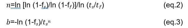
dove f�� e f�� sono le frazioni volumetriche iniziale e finale (solitamente f��=0.01 e f��=0.99) e ���� e ���� sono i tempi di inizio e fine trasformazione a temperatura costante.
Se �� nell'eq.1 rimane costante durante la trasformazione (cioè n è indipendente dalla temperatura) e b è solo una funzione della temperatura, il principio di Scheil (o regola dell’additività) può essere utilizzato per estendere il modello JMAK a condizioni non isoterme. [9]s
La distribuzione della temperatura all'interno del forgiato nel corso del tempo è ricavata utilizzando la legge di Fourier sulla conduzione e il trasporto del calore, insieme con la legge di conservazione dell'energia. Sono stati applicati metodi numerici per risolvere l'equazione del trasporto di calore e ottenere la distribuzione della temperatura, incorporando gli algoritmi per la descrizione delle trasformazioni di fase e il calore latente di trasformazione. L'inizio della trasformazione di fase è calcolato in base al tempo di incubazione per la nucleazione e alla legge ad-
ditiva di Scheil. [9, 10]
Poiché i tempi di inizio e fine trasformazione di fase in condizioni isoterme dipendono dalla dimensione dei grani austenitici e spesso si dispone di un diagramma TTT per una certa dimensione media di grano che può non coincidere con quella del trattamento di interesse, è stato sviluppato un algoritmo basato sull'approccio proposto da Kirkaldy [11], in cui l’effetto della dimensione del grano austenitico sul tempo di inizio trasformazione è espresso con un fattore 2N/8, dove N è la dimensione del grano espressa come numero ASTM.
La formazione della martensite, che si sviluppa dall'austenite non trasformata, è descritta tenendo conto che è funzione solo dal sottoraffreddamento rispetto alla temperatura critica di inizio formazione della martensite (MS). Generalmente, l’evoluzione della martensite (M) è calcolata mediante l'equazione proposta da Koistinen e Marburger: [12]
in cui la costante α è determinata in base a dati sperimentali (α vale circa - 0.011 per gli acciai bassolegati). L’eq.4 è ampiamente applicata, anche se l’andamento della frazione di martensite in funzione della temperatura è di tipo parabolico e non a forma sigmoidale, per cui si ha un lieve scostamento dai dati sperimentali ad inizio formazione della martensite, fino a percentuali del 10-20%. [13]
Rinvenimento
Il modello è dotato di un modulo, valido per gli acciai bassolegati e quelli inossidabili martensitici in grado di stimare la durezza dopo rinvenimento sulla base delle frazioni volumetriche dei costituenti microstrutturali formatisi dopo raffreddamento/tempra e di equazioni empiriche,
simili a quelle proposte da Maynier et al. [14], aggiornate in termini di coefficienti per gli acciai ad alto tenore di cromo (8-23%Cr), per le quali la durezza della bainite e della martensite si riduce in funzione della temperatura e tempo di rinvenimento.
Nel caso degli acciai inossidabili martensitici (tipo F6NM e 17-4PH), è stata introdotta una routine basata su un modello fisico che descrive l’evoluzione dell'austenite durante trattamenti di rinvenimento singoli e multipli. [2]
La validazione di questo algoritmo è stata effettuata su campioni, prelevati da forgiati in acciaio ASTM A182 F6NM o X3CrNiMo13-4, solubilizzati, rinvenuti in laboratorio a diverse temperature, comprese tra 600 e 700°C, per tempi dell'ordine delle ore. [2]
TUBI FORGIATI PER RISER
I componenti offshore soggetti a forti sollecitazioni meccaniche, come riser e J-collar sono forniti in gradi da API 5L X65 a X80. Richiedono una resistenza alla trazione molto elevata e tolleranze dimensionali ristrette. In generale, i tubi forgiati sono preferibili rispetto ai tubi laminati a caldo in caso di grandi diametri esterni (superiori a 18", 457 mm), grossi spessori di parete (WT), superiori a 20 mm, e piccoli lotti. Infatti, l'ordine minimo per un forgiato è di un solo tubo, mentre per i tubi laminati a caldo i lotti minimi sono di diverse tonnellate. Inoltre, un diametro interno (ID) controllato consente un migliore dimensionamento in fase di progettazione, riduce i costi di saldatura durante l'installazione dei tubi e riduce i movimenti vorticosi del fluido all'interno della tubazione.
Tubi forgiati di grande diametro e grosso spessore sono fabbricati mediante forgiatura su mandrino e successivo trattamento di tempra e rinvenimento (Q&T). Le tolleranze precise si ottengono con la lavorazione meccanica; pertanto occorre considerare un adeguato sovrametallo, con valori di spessore significativamente superiori a quelli dei tubi senza saldatura laminati a caldo durante il trattamento termico, a parità di spessore finale del tubo. Questo aspetto richiede un'adeguata progettazione metallurgica dei tubi forgiati per raggiungere i livelli di resistenza previsti e le proprietà d'impatto richieste a basse temperature.
Di seguito sono discussi i risultati dello sviluppo e della produzione di tubi forgiati temprati e rinvenuti (quenched and tempered, Q&T) di grado API 5L X80 PSL2, con tensione di snervamento minima pari a 555 MPa.
Design metallurgico mediante simulazioni virtuali e prove di laboratorio
Alcune analisi di sensibilità eseguite mediante modello hanno permesso di stabilire che, per realizzare i livelli di resistenza richiesti in tubi che al trattamento termico hanno spessori compresi tra 40 mm e 100 mm, è necessario inibire la formazione di ferrite e formare una frazione volumetrica di martensite a basso tenore di carbonio superiore al 10-30% durante il processo di tempra, altrimenti si dovrebbero impiegare temperature di rinvenimento troppo basse, incompatibili con le richieste di valori superiori di almeno 20 °C rispetto alle temperature di distensione
dopo saldatura (Post Weld Heat Treatment, PWHT) e con riflessi negativi sulla tenacità.
Oltre a sistemi di tempra efficaci, è necessaria un'adeguata temprabilità dell'acciaio, a seconda dello spessore (wall thickness, WT). Aggiunte oculate di Mn, Cr, Mo e Ni promuovono la formazione di bainite e di martensite, costituenti che contribuiscono ad aumentare la resistenza, senza effetti negativi sulla tenacità.
Ad esempio, sulla base dei risultati delle simulazioni, il tenore di Mn è stato aumentato fino all'1,6%; tenori maggiori si evitano per preservare la saldabilità e la resistenza all’infragilimento da idrogeno (hydrogen induced cracking, HIC). I contenuti di Cr e Ni sono stati mantenuti nell'intervallo tra 0,25% e 0,35% e quello del Mo tra 0.20% e 025% per migliorare la temprabilità. Valori più elevati di questi elementi non sono stati considerati sempre per preservare la saldabilità (generalmente, per il grado API 5L X80. il requisito per il carbonio equivalente è Ceq = C+Mn/6+(Cr+Mo+V)/5+(Ni+Cu)/15 < 0.50%). Per lo stesso motivo, il tenore di C è mantenuto tra 0.07% e 0.13%, con valori tendenzialmente più alti per gli spessori di tubo maggiori e per temperature di rinvenimento superiori a 650 °C.
Fondamentale per raggiungere i livelli di resistenza meccanica richiesti, è lo sfruttamento dell'indurimento per precipitazione, agendo sulle aggiunte di V e Nb.
A titolo di esempio, si riportano in Fig.1 i risultati di un'analisi di sensibilità condotta con il modello termo-metallurgico, a partire da un’analisi base, per studiare l'effetto di alcuni elementi, come C e V e della temperatura di rinvenimento sulla tensione di snervamento (yield strength, YS) e sul carico unitario a rottura (tensile strength, TS), nel caso di tubi forgiati con spessore WT = 68 mm durante tempra.
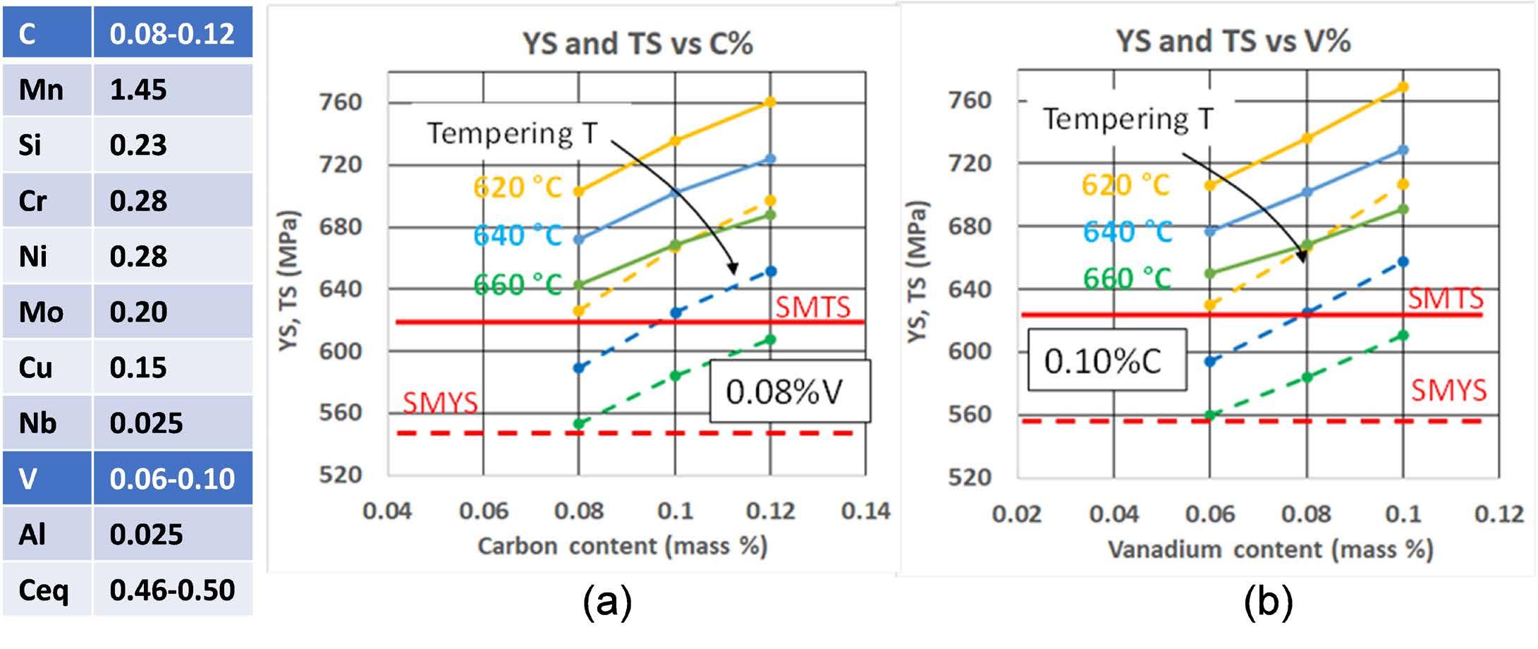
Fig.1 - Valori di snervamento e rottura calcolati a metà spessore per un tubo forgiato Q&T avente spessore di 68 mm in tempra: effetto del C (a) e del V (b) per diverse temperature di rinvenimento. / Values of YS and TS calculated at mid-wall for a Q&T forged pipe of 68 mm WT in quenching: effect of C (a) and V (b) contents for various tempering temperatures.
Il modello ha permesso di quantificare il miglioramento di YS e TS dovuto all'aggiunta di C dallo 0,08% allo 0,12% e di V dallo 0,06% allo 0,1%, per temperature di rinvenimento da 620 °C a 660 °C. Se si punta ad una temperatura di rinvenimento di 640°C, si dovrebbe aggiungere lo 0,1% di C e almeno lo 0,05% di V.
Anche l’incremento della dimensione dei grani austenitici migliora la temprabilità e ha un effetto positivo sulla resistenza meccanica. Secondo il modello, questo effetto è importante fino a quando le dimensioni arrivano a 30-40 μ m, quindi si verifica una saturazione. [15]
Poiché un grano austenitico grossolano è deleterio per la tenacità all'impatto, sono state eseguite prove di tempra e rinvenimento in laboratorio, a partire da spezzoni di tubi forgiati in un acciaio promettente, misurando le dimensioni medie dei grani (secondo ASTM E112) e le proprietà meccaniche a metà spessore, per due temperature di austenitizzazione (920 °C e 950 °C) e varie temperature di rinvenimento, riproducendo anche l'effetto del PWHT (Tab.1).
Tab.1 - Prove di laboratorio su materiali di grado X80: effetto della dimensione dei grani austenitici (AGS) e della temperatura di rinvenimento su snervamento (YS), rottura (TS) ed energia Charpy assorbita (CVN). / Laboratory tests on grade X80 materials: effect of austenite grain size (AGS) and tempering temperature on yield strength (YS), tensile strength (TS) and absorbed Charpy energy (CVN).
(*) Additional SPWHT carried out at 640 °C for 12 hours
Naturalmente, aumentando la temperatura di rinvenimento da 620 °C a 650 °C si riduce la resistenza meccanica, che però rimane a livelli accettabili, e migliora la tenacità all'urto (Tab.1).
L'innalzamento della temperatura di austenitizzazione
favorisce la formazione di grani di austenite grossolani e la microstruttura è più bainitica/aciculare (Fig.2), con una sensibile riduzione dei grani di ferrite poligonale (polygonal ferrite, PF).
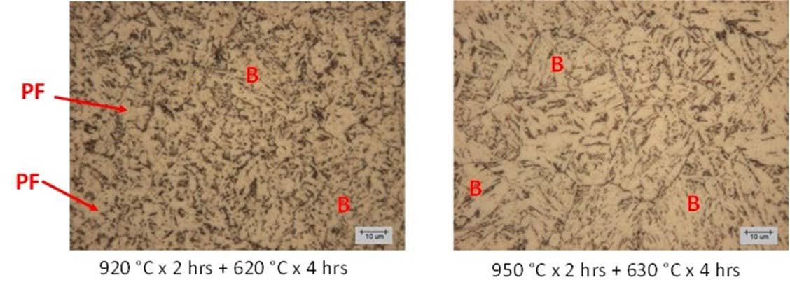
Fig.2 - Microstrutture a metà spessore dopo trattamento di tempra e rinvenimento (Q&T) in laboratorio. Sezione trasversale da tubo forgiato di grosso spessore in tempra (WT = 68 mm). Reagente: nital 2%. Microscopia ottica. / Microstructures at mid-wall after Q&T laboratory tests. Transverse specimens taken from a forged heavy wall pipe (WT = 68 mm in quenching). Etching: nital 2%. Light microscopy.
La struttura bainitica dopo rinvenimento è mostrata ad alto ingrandimento in Fig.3.
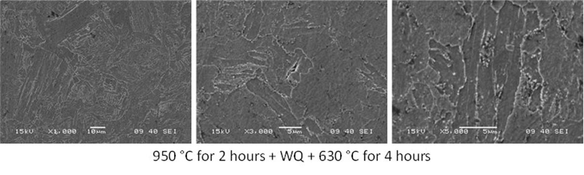
Fig.3 - Microstrutture a metà spessore dopo trattamento di tempra e rinvenimento (Q&T) in laboratorio. Sezione trasversale da tubo forgiato di grosso spessore in tempra (WT = 68 mm). Reagente: nital 2%. Microscopia Elettronica a Scansione (SEM). / Microstructures at mid-wall after Q&T laboratory tests. Transverse specimens taken from a forged heavy wall pipe (WT = 68 mm in quenching). Etching: nital 2%.
Scanning Electron Microscopy (SEM).
Sono presenti lamelle con spessore inferiore a 2 μ m. Si notano anche piccoli grani di dimensioni inferiori a 5 μ m.
È interessante notare che quando il grano austenitico medio cresce da 27 μ m a 42 μ m, l'energia assorbita dal provino Charpy con intaglio a V (CVN) rimane ancora elevata ad una temperatura di rinvenimento di 630 °C (Tab.1). Il modello metallurgico indica che per sviluppare la microstruttura target, per una velocità di raffreddamento da 5 a 2 °C/s, tipica di tubi con spessore da 60 a 100 mm du-
rante la tempra, è necessario un acciaio con Ceq = 0,470,50% e AGS = 25-35 μ m.
Nel caso di spessore pari a 40-60 mm e AGS = 20-25 μ m, appare adeguato un acciaio con Ceq = 0,43-0,46%. Inoltre, il contenuto di V deve essere sempre mantenuto nell'intervallo 0,04-0,08%, per avere un rafforzamento sufficiente. Contenuti di V più elevati possono diminuire la tenacità all'impatto. Inoltre, le simulazioni virtuali mostrano che impiegando vasche di tempra molto efficaci, ossia
con elevati coefficienti di scambio, si sviluppano a centro spessore adeguate velocità di raffreddamento e durezze, anche per grossi spessori, ma in corrispondenza dello strato superficiale i valori delle velocità di raffreddamento sono sensibilmente superiori e le durezze possono essere ben superiori a 237 HB (Fig.4), per cui il prodotto non sarebbe adatto ad impiego in ambiente “sour”.
Mediante modello è possibile stabilire il sovrametallo e le condizioni di trattamento termico ottimali, in partico-
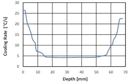
OD → depth = 0 mm; ID → depth = 68 mm
lare di rinvenimento, per raggiungere il grado a centro spessore ed evitare picchi di durezza in superficie dopo la lavorazione meccanica che asporta uno strato superficiale di opportuno spessore. A riguardo si tenga presente che le simulazioni virtuali mostrano che dopo rimozione di 10-15 mm i valori di durezza in superficie si avvicinano molto a quelli presenti a metà spessore del tubo (Fig.4), per cui anche la produzione di tubi forgiati di grado X80 per sour service risulta possibile.
mm depth from OD
from OD
from ID
mm depth from ID 280 N.A.
Fig.4 - Simulazioni virtuali: velocità di raffreddamento durante tempra in acqua e durezze dopo rinvenimento a 650 °C nello spessore di un tubo forgiato (WT = 68 mm). / Virtual simulations: cooling rates during water quenching and hardness after tempering at 650 °C through the thickness of a forged pipe (WT = 68 mm).
Esperienze industriali
È stata effettuata una produzione di tubi forgiati con uno spessore di 68 mm in fase di tempra. L'austenitizzazione è stata eseguita a 940 °C per 1,5 ore e il rinvenimento a 640 °C per 3 ore. L'obiettivo era quello di produrre tubi X80 di grande diametro (OD = 533,4 mm), con spessore finale di
22,2 mm e 12 m di lunghezza.
La chimica dell'acciaio identificata come promettente in base al design metallurgico è mostrata in Tab.2, dove è messa a confronto con i tenori massimi chiesti dall'utilizzatore finale.
Tab.2 - Analisi chimica utilizzata per fabbricare tubi forgiati di grado API 5L X80 QT, confrontata con i contenuti massimi richiesti dall'utilizzatore finale. / Chemical composition used for API 5L X80 QT forged pipes, compared to maximum contents required by end-user.
Dopo il trattamento di tempra e di rinvenimento industriale, è stato campionato un prolungamento dai tubi e sono state determinate le proprietà meccaniche, sia nella condizione Q&T sia dopo trattamento PWHT simulato (Tab.3).
Tutti i requisiti sono stati raggiunti, anche se la tensione di
snervamento è al limite, vicina al valore minimo consentito dopo SPWHT. La tenacità all'impatto è risultata molto buona a - 20 °C, con valori di area duttile (shear area) tra il 70% e il 90% ed espansione laterale dei provini da 1,8 a 2,3 mm. La durezza eseguita su entrambe le estremità del tubo dopo Q&T (spessore 68 mm) ha dato valori compresi tra 232 HB e 248 HB.
Dopo la lavorazione per ottenere un WT finale di 22,2 mm,
la durezza è scesa a 216-224 HB. Pertanto, questo tubo può essere adatto al servizio sour, poiché la durezza massima è inferiore a 237 HB. Inoltre, questi risultati indicano che, attraverso la messa a punto della composizione chimica e delle condizioni di processo, è possibile ottenere facilmente anche il grado API 5L X70 idoneo per ambiente sour.
Tab.3 - Proprietà meccaniche realizzate a metà spessore di tubi forgiati dopo trattamento industriale di Q&T e successivo SPWHT, confrontate con i requisiti. / Mechanical properties at mid-wall of X80 forged pipes after industrial Q&T and subsequent SPWHT, compared to the requirements.
TUBI E BUSSOLE FORGIATE PER IMPIEGHI
STRUTTURALI
temprate e rinvenute, con le dimensioni e le proprietà mostrate in Tab.4. (*) Simulated PWHT: 638 °C for 12 h
Per questa applicazione sono richiesti tubi/bussole,
Tab.4 - Geometria e proprietà meccaniche di tubi e bussole Q&T per applicazioni strutturali. / Size and mechanical properties of Q&T pipes and sleeves for structural applications.
Nel caso 1 (spessore finale 85 mm), la tensione di snervamento minima è di 740 MPa, mentre per il caso 2 con spessore finale di 134 mm, si richiede un carico unitario a rottura pari a 815-918 MPa. Visti gli spessori in gioco e i livelli di resistenza richiesti, per il caso 1 si è sviluppato un acciaio a basso carbonio (0.14-0.18%C), basso-legato al Cr-Ni-Mo, micro-legato con Nb e V, mentre per il caso 2 si è ricorso ad un acciaio a medio carbonio (0.35-0.45%C),
basso-legato al Cr-Ni-Mo, micro-legato al vanadio.
Per il caso 1, a partire da un tenore di C di 0.16% e tenore degli elementi di lega riportati in Tab.5, si è valutato mediante modello l’effetto di alcune variazioni nei tenori di Mn, Cr, Ni, Mo e V, sempre mostrati in Tab.5, sulla resistenza meccanica a centro spessore dopo tempra (velocità di raffreddamento media di circa 2 °C/s) e rinvenimento (temperature di 580 °C e 600 °C).
In base ai risultati di Tab.5, è stata definita l’analisi di una colata (Tab.6) con cui sono stati fabbricati i tubi, le cui pro-
prietà meccaniche dopo Q&T sono mostrate in Tab.6. Esistono margini per aumentare la temperatura di rinvenimento a 600 °C, al fine di migliorare la tenacità del materiale.
Per il Caso 2, le simulazioni virtuali danno per lo spessore al trattamento termico una velocità media di raffreddamento di circa 1.2 °C/s. Perciò, si sono eseguiti ulteriori calcoli con il modello per valutare i benefici dovuti ad un’aggiunta di vanadio in termini di rafforzamento (Tab.7).
Tab.5 - Simulazioni virtuali per il caso 1: effetto dell’analisi chimica (massa %) e della temperatura di rinvenimento. / Virtual simulations for case 1: effect of chemical composition (mass %) and tempering temperature.
Taust = 940 °C for 2 hrs; tempering T = 580 and 600 °C for 2 hrs
Tab.6 - Caso 1: analisi della colata industriale (massa %) e proprietà meccaniche dei tubi forgiati dopo trattamento industriale di Q&T. / Case 1: industrial heat analysis (mass %) and mechanical properties of forged pipes after industrial Q&T treatment.
(MPa) TS (MPa) Elong. RoA
Austenitizing: 940 °C for 2 hrs + Quenching +Tempering: 580 °C for 2
Tab.7 - Simulazioni virtuali per il caso 2: effetto dell’aggiunta di vanadio e della temperatura di rinvenimento. / Virtual simulations for case 2: effect of Vanadium addition and tempering temperature.
Al fine di raggiungere i livelli di carico unitario a rottura richiesti, si è optato per la chimica al vanadio e per una temperatura di rinvenimento di 640 °C. La fabbricazione industriale della bussola (Tab.8) ha mostrato che, con il tenore di vanadio (0.045%) della colata
industriale utilizzata e le condizioni di trattamento individuate come promettenti, si sono ottenute le proprietà meccaniche richieste ed una microstruttura di martensite/ bainite rinvenuta a grano fine (Fig.5).
Tab.8 - Caso 2: analisi della colata industriale (massa %) e proprietà meccaniche della bussola forgiata dopo trattamento di Q&T. / Case 2: industrial heat analysis (mass %) and mechanical properties of forged sleeve after Q&T treatment.
Elong. RoA
Condizioni di trattamento/ Heat treatment conditions
Austenitizing: 870 °C for 3 hrs + Quenching +

Fig.5 - Caso 2: microstruttura dopo trattamento di tempra e rinvenimento (Q&T) della bussola. Sezione trasversale. Reagente: nital 2%. Microscopia ottica. / Case 2: microstructure after Q&T treatment of the sleeve. Transverse specimens. Etching: nital 2%. Light microscopy.
Lo sviluppo e l'applicazione di strumenti di simulazione virtuale hanno permesso di migliorare la progettazione dei cicli termici per forgiati, al fine di ottenere le microstrutture e le proprietà meccaniche desiderate. Gli algoritmi e i modelli sviluppati offrono un accesso semplice e strutturato a una serie completa di opzioni per stimare gli effetti dei parametri di trattamento termico e degli elementi di lega sull'evoluzione della temperatura, sulla trasformazione di fase e sulla microstruttura e durezza finali, per varie classi di acciai. Gli esempi applicativi mostrati, relativi a forgiati in acciai microlegati, utilizzati nel settore delle macchine per movimento terra e dei tubi riser, hanno evidenziato che questi strumenti di simulazione consentono di: − condurre un’analisi di sensibilità, senza ricorrere a prove industriali che richiedono tempo e risorse;
− ottimizzare i trattamenti termici in uso, al fine di ottenere la microstruttura e la resistenza meccanica desiderata; − mettere rapidamente a punto le strategie di trattamento termico per nuovi componenti (materiale e/o geometria).
Finanziamenti: Questa ricerca è stata finanziata dal Ministero delle imprese e del made in Italy (MIMIT), Progetto n. F-220024-00-X47 (INNOTECH).
Ringraziamenti: Si ringrazia G. Franchini per l'autorizzazione alla pubblicazione di questo lavoro e tutti i colleghi che hanno contribuito ad eseguire le prove di laboratorio e su scala industriale, nonché alla raccolta e all'analisi dei dati. Si ringrazia inoltre Rina Consulting - Centro Sviluppo Materiali per il contributo allo sviluppo e alla validazione del modello termo-metallurgico proprietario.
[1] Di Schino A, Mechanical Properties and Microstructure of Forged Steels, Metals 2021, 11, 1177. https://doi.org/10.3390/met11081177.
[2] Anelli E, Colosio S, Di Nunzio PE, Heat Treatment Guidelines of Supermartensitic Steel Forgings by Metallurgical Modeling, Proceedings of the 4th Mediterranean Conference on Heat Treatment and Surface Engineering (MCHTSE) and Int. Conf. on Thermal Process Modeling and Simulations (TPMS), Paper no. T5_010, 17-19 April 2024, Lecce, Italy, ed. AIM, ISBN 978-88-98990-34-4.
[3] Anelli E, Optimization of quenching and tempering treatment for steel forgings through virtual simulations, La Metallurgia Italiana, October 2022, pp. 20-39.
[4] Anelli E, Lucchesi M, Chugaeva A, Microstructural Prediction of Heat Treated Steel Forgings for Severe Applications. Materials Science Forum 2021, Trans Tech Publications Ltd, Switzerland, ISSN: 1662-9752, Vol.1016, pp 236-242.
[5] Anelli E, Lucchesi M, Chugaeva A, Application of numerical simulation to predict microstructure and hardness of Q&T steel forgings. In Proceedings of METEC and 4th ESTAD (European Steel Technology and Application Days), CCD Congress Center Düsseldorf, Germany, June 24-28, 2019, Steel Institute VDEh, TEMA Technologie Marketing AG.
[6] Anelli E, Lucchesi M, Chugaeva A, Virtual simulation applied to heat treatment of forgings, La Metallurgia Italiana n. 9, 2018, pp. 45-53.
[7] Maynier Ph., Dollet J, Bastien P, Prediction of microstructure via empirical formulae based on CCT diagrams, in: D.V. Doane, J.S. Kirkaldy (Eds.), Hardenability Concepts with Applications to Steel, AIME, Chicago, 1978, pp. 163-178.
[8] Blázquez JS, Manchón-Gordón AF, Ipus JJ, Conde CF, Conde A. On the Use of JMAK Theory to Describe Mechanical Amorphization: A Comparison between Experiments, Numerical Solutions and Simulations. Metals 2018, 8, 450; doi:10.3390/met8060450.
[9] Scheil E. Anlaufzeit den Austenitumwandung, Arch. Eisenhuttenwesen 1935, Vol.8, pp. 565-567.
[10] Anelli E. Application of Mathematical Modelling to Hot Rolling and Controlled Cooling of Wire Rods and Bars. ISIJ International 1992, 32, pp.440-449.
[11] Kirkaldy JS. Diffusion-Controlled Phase Transformations in Steels, Scand. J. Met. 1991, 20, pp. 50-61.
[12] Koistinen DP, Marburger RE. A general equation prescribing extend of austenite-martensite transformation in pure Fe-C alloys and plain carbon steels. Acta Metall. 1959, pp. 59-60.
[13] Huyan F, Hedström P, Borgenstam A. Modelling of the fraction of martensite in low-alloy steels. Materials Today: Proceedings 2S 2015, pp. S561 – S564.
[14] Maynier Ph., Jungmann B, Dollet J, Creusot-Loire system for the prediction of the mechanical properties of low-alloy steel products, in: D.V. Doane, J.S. Kirkaldy (Eds.), Hardenability Concepts with Applications to Steel, AIME, Chicago, 1978, pp. 518-545.
[15] Anelli E, Colosio S. Metallurgy and Production of Low-Carbon Weldable Forged Pipes, Proceedings of the 22nd International Forgemasters Meeting, Paper no. IFM_027, 27-30 May 2024, Milano, Italy, ed. AIM, ISBN 978-88-98990-35-1.
The results of the development of steel forgings with yield strength from 520 MPa to 900 MPa are presented. The aim was to identify chemical compositions and heat treatment conditions to achieve the desired strength, combined with good impact toughness. For this purpose, virtual simulations able to predict the thermal and microstructural evolution during the heat treatment were applied. The tuning of the process conditions was also carried out by reproducing the thermal cycles identified as optimal, first in the laboratory and then on an industrial scale, for the evaluation of the impact toughness. Application examples are presented for forged micro-alloyed steels, used for risers, structural applications and in the earthmoving sector.
KEYWORDS: FORGINGS, HEAT TREATMENT, NUMERICAL SIMULATION, PHASE TRANSFORMATION, MICROSTRUCTURE, HARDNESS, STRENGTH, IMPACT TOUGHNESS;
E. Bertarelli, M. Cassola, A. Fortini, M. Merlin
In industrial practice, heat treatment companies are usually required to perform induction hardening on parts with different metallurgical supply conditions resulting from different heat treatment routes previously applied. As a result, understanding the effect of material supply conditions on the induction hardening process parameters is of great interest for heat treatment companies. This knowledge enables the proper adjustment of process parameters, ensuring optimal outcomes and consistency across diverse material conditions. In this study, shafts manufactured in UNI EN 42CrMo4 steel were subjected to induction hardening treatment starting from different supply conditions. The study focuses on two distinct case studies: • Case study 1 investigates the influence of different preliminary heat treatment routes (normalizing, quenching and tempering); • Case study 2 explores the effect of repeated induction hardening, namely the hardening on a part that has been already hardened previously.
KEYWORDS: INDUCTION HARDENING, SUPPLY CONDITIONS, MICROSTRUCTURE, HARDNESS;
Induction hardening is currently used to increase the performance of a wide variety of mechanical components, including axles, shafts, and gears, for several applications, especially in vehicles in the automotive field. It is a reliable and time-saving process that can be used to selectively harden portions of the above-mentioned parts to improve strength, hardness, wear resistance, and fatigue behavior [1]. In contrast to case hardening and nitriding, induction hardening does not require heating the whole part and allows the hardening of the material only where needed. The optimization of the process parameters is fundamental for achieving the desired surface mechanical properties. The design of the inductor, its geometry, and the selection of the induction heating frequency are crucial to precisely control the localized heating of the material; the temperature distribution during heating must be as uniform as possible and achieved in the shortest time to maximize the efficacy of the process [2]. The metallurgical changes should occur only within the established thickness, minimizing the heating effects on adjacent areas to preserve the component’s overall integrity [3]. Induction hardening consists of three different steps, i.e. austenitization, quenching and tempering, but the metallurgical supply conditions of the materials can affect the final properties of the hardened surface. The
E. Bertarelli, M. Cassola
TIMAF S.n.c., via Ciauri 15, 29121 Piacenza (Italy)
A. Fortini, M. Merlin
Department of Engineering (DE) – University of Ferrara, via Saragat 1, 44122 Ferrara (Italy)
literature highlights that bulk pre-heat treatments, such as normalizing, quenching and tempering, play a critical role in determining the outcome of the process [3,4]. In this paper, two case studies typical of industrial practices are collected to point out that not only the nominal chemical composition of the steel but also the supply conditions are essential factors to be considered to guarantee the expected microstructure and mechanical properties.
Two different case studies were investigated in this industrial research, detailed as follows. All heat treatments were performed at TIMAF S.n.c. heat treatment factory. Chemical analysis hardness testing and Optical Microscopy (OM) inspections were conducted at TIMAF S.n.c. Metallurgical Laboratory, while further microscope analyses with a Scanning Electron Microscope (SEM) were executed at the Department of Engineering (DE) of the University of Ferrara. A Nikon Eclipse LV150N (Nikon Corp., Tokyo, Japan) was used for OM analyses, whereas a Zeiss EVO MA15 (Carl Zeiss, Jena, Germany) scanning electron microscope was adopted for SEM investigations. The shafts were all induction-hardened on a SAET 3MBE induction hardening machine with a vertical setup. During
the process, the part rotates around its axis while a ring inductor translates in the axial direction with a supply current frequency f equal to 15 kHz. A polymer-based quenching solution is used for quenching.
At TIMAF S.n.c., chemical composition was determined by a GNR S7 Metal Lab Plus Optical Emission Spectrometer (OES). Samples were ground and polished according to the standard metallographic preparation procedures. Rockwell hardness was measured by a Future-Tech LC200RB hardness tester (Future-Tech Corp., Kawasaki, Japan) according to the UNI EN ISO 6508-1 standard [5]. Vickers hardness (HV10, HV1, HV0.1) and hardness profiles were recorded by an OMAG WIKI200JS microhardness tester (OMAG, Induno Olona, Italy), according to UNI EN ISO 6507-1 [6] and UNI 11153-3 [7] standards.
First case study: hollow shafts with various supply conditions
Three hollow shafts made of 42CrMo4 steel, according to the UNI EN ISO 683-2:2018 standard, with an outer diameter of 40 mm and an inner diameter of 15 mm, were used for this case study. The chemical composition is detailed in Tab.1.
Tab.1 - Measured chemical composition (wt. %) of the 42CrMo4 steel. Mean values (5 measurements).
All shafts were normalized at 870 °C for 2 hours (hereinafter referred to as +N), whereas only two of them were subsequently austenitized at 860 °C for 2 hours, oil quenched, and respectively tempered at 400 °C (hereinafter referred to as +QT(400)) and 600 °C (hereinafter referred to as +QT(600)) for 2 hours.
After the heat treatments, the shafts were all inductionhardened at the TIMAF S.n.c. plant on an induction hardening machine with a vertical setup. In this case, the induction hardening process was set up to guarantee, according to the final Customer’s request, an effective hardening depth of Tps20 with a surface hardness class of 58 HRC according to UNI 10932:2001 standard [8]. This means that an effective hardening depth of 2 mm with a tolerance of +1,5 mm, a surface hardness in the range of
58 - 62 HRC and a limit hardness of 523 HV1 was the target. Finally, from each shaft, three transversal sections were cut to obtain three annular samples of 10 mm in thickness; one of the three samples was maintained in the inductionhardened condition, while the others were tempered at 140 °C for 2 hours (T140) and 170 °C for 2 hours (T170), respectively.
Two shafts in 42CrMo4 steel, according to the UNI EN ISO 683-2:2018 standard, with an outer diameter of 73,5 mm, were used for this case study. The chemical composition is detailed in Tab. 2.
Tab.2 - Measured chemical composition (wt. %) of the 42CrMo4 steel. Mean values (5 measurements).
Shafts were provided in quenched and tempered conditions by the Customer. The induction-hardening process was set up to guarantee, according to the final Customer’s request, an effective hardening depth of Tps30 with a surface hardness class of 58 HRC according to UNI 10932:2001 standard [8]. This means that an effective hardening depth of 3 mm with a tolerance of +2 mm, a surface hardness in the range of 58 - 62 HRC and a limit hardness of 523 HV1 was the target.
The first shaft was induction hardened one time. The second shaft was induction hardened three times in sequence, with a holding time of 5 minutes, with the water cooling system activated to have near zero residual heat in the part before executing the following hardening cycle. Both shafts were finally tempered at 170 °C for 2 hours.
First case study: hollow shafts with various supply conditions
In Tab. 3, all hardness and microhardness data acquired at the surface and the bulk of the steel before and after being induction-hardened and/or tempered at 140 °C and 170 °C are collected. Before induction hardening, the steel in the normalized condition shows the lowest surface hardness (31 HRC), even if the bulk hardness (350 HV10) is higher than that after quenching and tempering at 600 °C (315 HV10). Each heat-treated condition shows the conventional trend of decreasing surface hardness versus tempering temperature.
Figure 1 summarizes the obtained hardening depth for the different process routes. The reported differences in terms of effective hardening depth are not significant for generic industrial applications: when specific loads are not critical, the mechanical part performances are expected to be comparable for the different cases. This finding confirms that induction hardening effectively “overwrite” both +N or +QT metallurgical conditions. As expected, +QT(400) and +QT(600) samples show diffe-
rent base material hardness: this results in different hardness profile trends in the transition zone and thus in a shift of approximately 0.3 mm in effective hardening depth. The +N samples are aligned in terms of effective hardening depth to +QT(600) samples. It is worth to note that tempering up to 170 °C does not significantly impact the hardening depth. However, +N shows variations of measured hardening depth after tempering, while a strong trend is not found for +QT.
As reviewed in literature [9], +QT prior structure is the most favorable, ensuring rapid transformation, with a fast and consistent response of the steel to induction hardening, minimum grain growth and shape/size distortion. Potentially, this condition can lead to higher hardness and higher effective depth. If the initial microstructure has a significant amount of coarse pearlite and, most importantly, coarse ferrites or clusters or bands of ferrites, then the structure is not considered favorable. After quenching, a mixed ferritic-martensitic microstructure can form. In the present +N case study however, the prior microstructure is not characterized by coarse-grained ferrite or pearlite and this is demonstrated to allow the induction hardening process to successfully occur, similarly to the +QT case. But, as mentioned in [9], the local required induction hardening temperature depends on the material’s prior microstructure: higher temperatures are required to achieve homogeneous austenite (in terms of carbon homogeneity) in +N rather than +QT conditions. Focusing on the transition zone, where the transformation is obtained by thermal diffusion, we believe this effect is emphasized. Hence, in the +N metallurgical condition, after quenching the martensite structure could be not fully uniform: tempering is then driving additional transformations at different temperatures, resulting in variations of detected hardening effective depth.
Tab.3 - Hardness data (HRC: mean of n. 5 measurements; HV10: mean of n. 5 measurements; HV1: mean of n. 20 measurements).
HEAT-TREATED CONDITION BULK HARDNESS (mean values) INITIAL SURFACE HARDNESS (mean values)
Quenched and tempered at
Quenched and tempered at
HV10
HV10
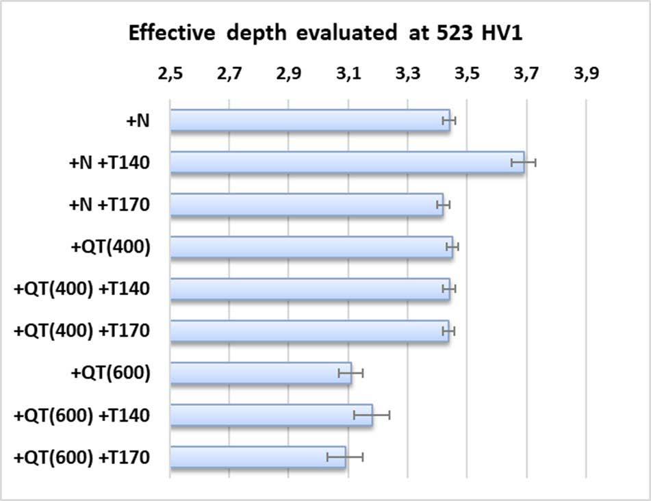
Fig.1 - Effective hardening depth for the studied process routes (mean of n. 3 microhardness profiles).
Fig. 2 summarizes the SEM micrographs of the steel in the +N and +QT(600) conditions after the induction hardening treatment by comparing the bulk and induction-hardened zones. From the low-magnification SEM micrographs (Fig. 2a and 2d), the effects of the different supply conditions could be observed. As for the +N condition, in the bulk region (Fig. 2c), the microstructural constituents were identified as ferrite and perlite, with a slightly higher amount of ferrite than that of perlite due to air cooling during normalizing: the appearance of perlite is quite like upper bainite due to the hardenability the 42CrMo4
steel. This microstructure is compatible with the good hardenability of the investigated steel in the +N condition and justifies the initial high values of hardness in the normalized condition (see Tab. 2). By contrast, in the induction-hardened region (Fig. 2b), the microstructure is very fine and identified as high tetragonal martensite. Concerning the +QT(600) condition, the microstructure in the bulk zone (Fig. 2f) can be ascribed to tempered martensite; in the induction-hardened region (Fig. 2e), the martensitic phase becomes finer than in the bulk region.
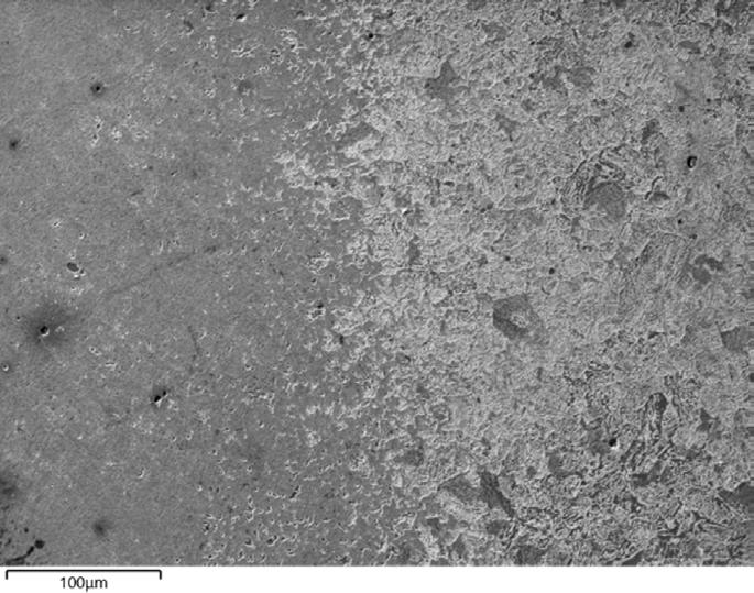
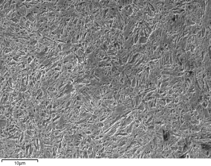
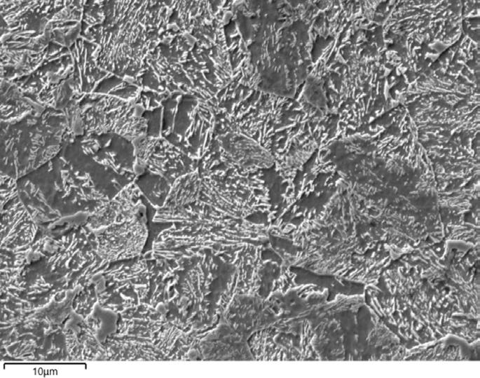
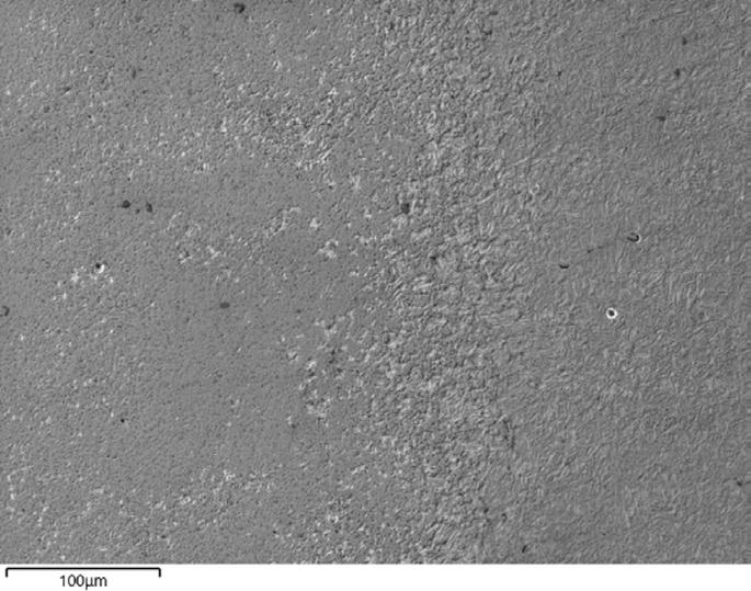
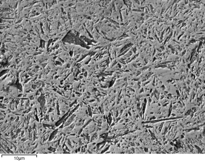

Fig.2 - SEM micrographs: a) +N, low magnification micrograph of the transition region; b) + N, induction-hardened region; c) +N, bulk region; d) +QT(600), low magnification micrograph of the transition region; e) +QT(600), induction-hardened region and f) +QT(600), bulk region.
To study the hardness transition zone, namely the hardness drop in the limit zone between the inductionhardened region and the base material, hardness profiles were performed on the cross sections of the +N and +QT(600) samples across the transition zone. The results are reported in Fig. 3 and they show a steeper decrease in hardness in the transition zone in the +N condition (Fig.
3a) with respect to that of the +QT(600) condition (Fig. 3b). This agrees with the different effects caused in the microstructure in the transition zone by the induction hardening process.
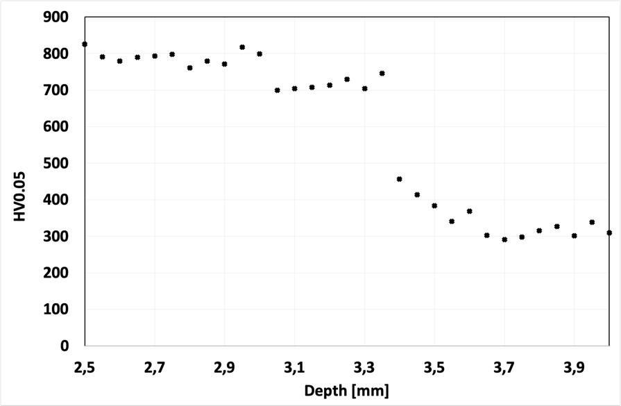
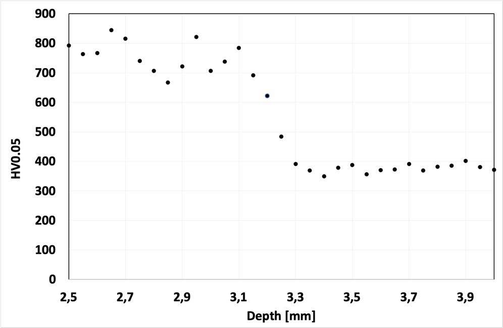
Fig.3 - Microhardness HV0.05 profiles in the transition zone: a) +N; b) +QT(600).
Second case study: shafts undergoing repeated hardening
Hardness and microhardness tests were performed on the surface and the cross-section of the analyzed samples and data are collected in Tab. 4. From a general standpoint, no significant variations can be highlighted in
terms of surface hardness and effective hardening depth when comparing a single induction hardening cycle, i.e. one repeat, with three sequential hardening cycles, i.e. three repeats. This finding matches the empirical rule that subsequent induction hardening overrides the previous process if similar parameters are applied.
Tab.4 - Hardness data (HRC: mean of n. 5 measurements; HV10: mean of n. 5 measurements; HV1: mean of n. 20 measurements).
The analysis of the hardness profiles (Fig. 4) points out that, while comparable microhardness is detected on the hardened zone, a difference is kept in light of the transition zone. The OM inspection reported in Fig. 5 confirms that repeated execution of the induction hardening process leads to the creation of an extended interface zone between the base material and fully transformed (martensitic) material. The higher thickness of the transition zone in the one repeat condition (Fig. 6a) than that in the three repeats condition can also be observed by the SEM micrographs. By comparing the micrographs reported in Fig. 6c and Fig.
6f, which refer to the induction-hardened zones of the two different conditions, just a slight increase in size of the platelet-like martensitic microstructure can be detected after three sequential hardening cycles; nevertheless, no significant variations in the hardness were detected (Fig. 4a). No thermal effects were induced to the quenched and tempered microstructure in the bulk zone (Fig. 6h).

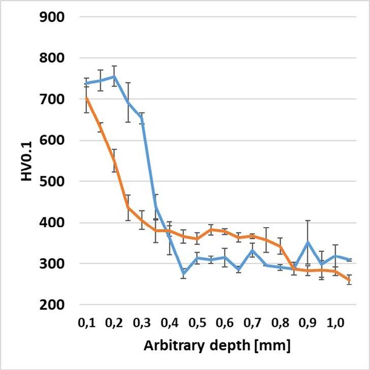
Fig.4 - (a) Microhardness HV1 profiles after induction hardening (AVE and SD on 3 profiles).
(b) Microhardness HV0.1 profiles, detail on hardness transition zone (AVE and SD on 5 profiles).
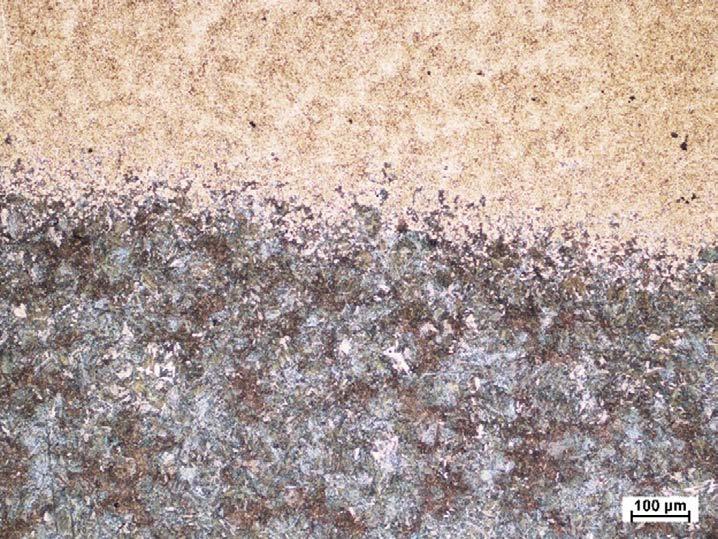
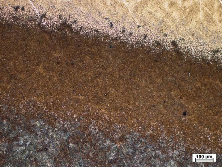
Fig.5 - OM micrographs of transition zone: a) 1 induction hardening cycle; b) 3 induction hardening cycles.
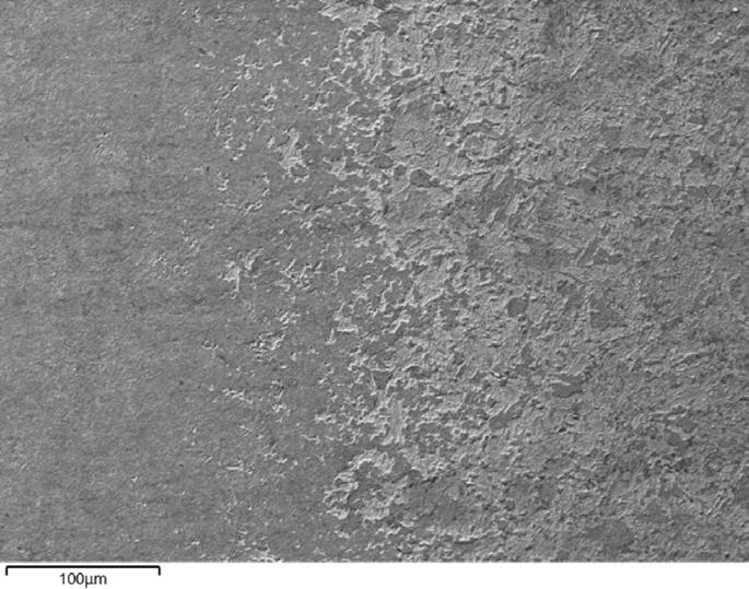
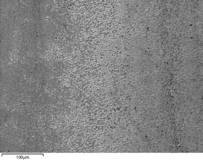
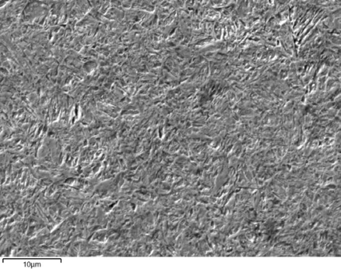
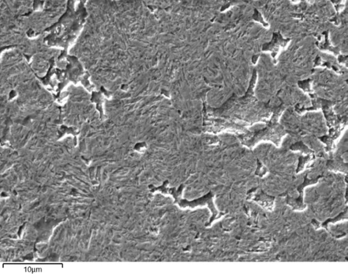
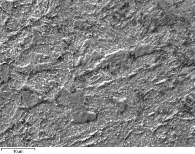
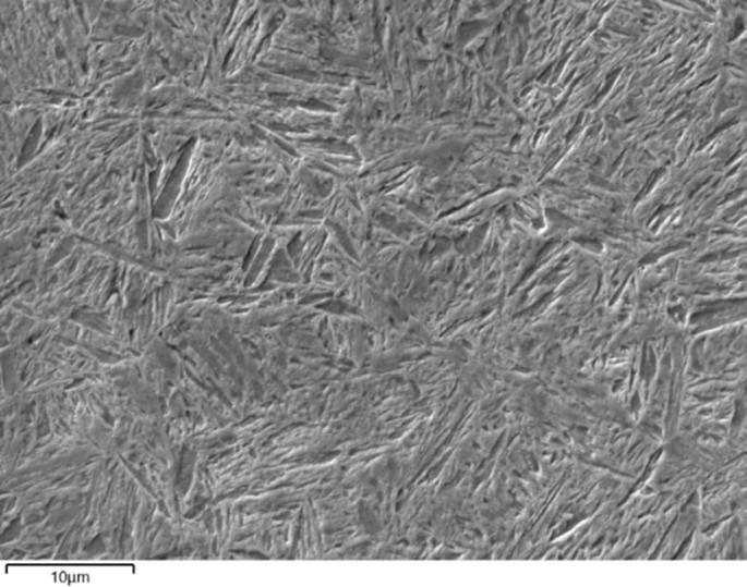
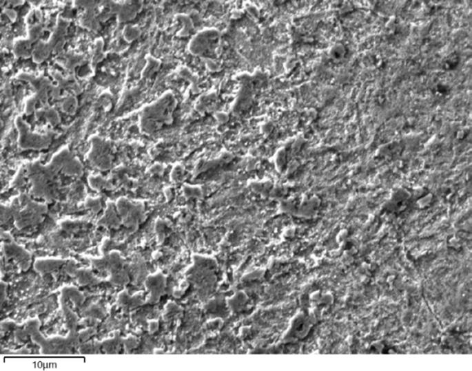
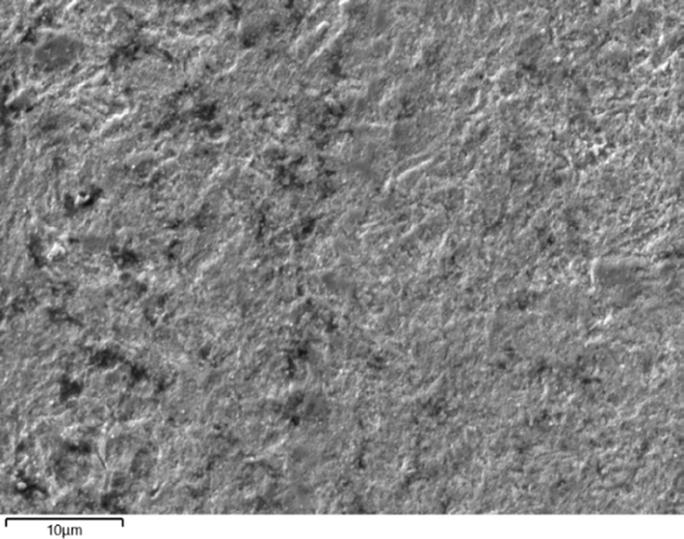
Fig.6 - SEM micrographs: a) and b) low magnification micrograph of the transition region for 1 and 3 induction hardening repeats, respectively; c), d), e) induction-hardened, transition and bulk regions for 1 repeat; f), g), h) induction-hardened, transition and bulk regions for 3 repeats.
In this work, two case studies were deeply investigated to point out how several key factors can impact the microstructure and the mechanical properties of induction-hardened steel parts in industrial practice. Apart from the induction hardening parameters related to the induction hardening machine setup (inductor geometry, current frequency, translation inductor speed, quenching phase, etc.), the results show that the metallurgical supply condition of steel and/or the prior applied heat treatments play a role in the determination of the final microstructure and thus the mechanical properties.
Case study n. 1 showed that, after induction hardening, surface hardness and effective hardening depth in a UNI EN 42CrMo4 steel are slightly influenced by the initial metallurgical supply condition, either normalized or quenched and tempered. By analyzing microhardness data, supported by microstructure investigations, it was found that both the microstructure and the local
mechanical properties in the transition zone differ in the different considered sample conditions. This could potentially impact the mechanical performances of the part under severe loading conditions, requiring dedicated investigations and potentially mechanical testing of parts, to achieve a suitable process optimization. Nevertheless, based on the TIMAF S.n.c. experience gained after extensive interaction with Customers, when applications are not critical and specific loads are not so high, no issues are expected.
Case study n. 2 showed that no significant change in hardness and effective hardening depth is achieved when the induction hardening is repeated up to 3 times in the same location. Micrographic inspection and low-load hardness measurements reveal that the transition zone between the hard layer and base material is strongly impacted by the repeated induction hardening process.
Memorie scientifiche - Trattamenti termici
[1] V. Rudnev. Induction Hardening of Gears and Critical Components. Gear Technology. September/October 2008, 58-63.
[2] M. Horynová, M. Juliš, L. Cˇelko, J. Švejcar. Failure analysis of induction hardened injector body. Engineering Failure Analysis, 56, 2015, 538-544.
[3] V.I. Rudnev, D. Loveless, R. Cook, M. Black. Induction Hardening of Gears: A Review. Heat Treatment of Metals, 2003, 4, 97-103.
[4] C. Rathinasuriyan, K. Karthik, S. Udhayaraj, Sunil Bishwakarma. Investigation of induction hardening on heat-treated EN8 steel by alternately timed quenching process. Materials Today: proceedings (article in press).
[5] UNI EN ISO 6508-1:2023 – Materiali metallici - Prova di durezza Rockwell - Parte 1: Metodo di prova – Metallic materials - Rockwell hardness test - Part 1: test method.
[6] UNI EN ISO 6507-1:2023 – Materiali metallici - Prova di durezza Vickers - Parte 1: Metodo di prova – Metallic materials - Vickers hardness test - Part 1: test method.
[7] UNI 11153-3:2006 – Misurazione dello spessore di strati superficiali induriti su elementi di lega ferrosa - Tempra superficiale.
[8] UNI 10932:2001 – Trattamenti termici dei materiali metallici Tempra superficiale dei materiali ferrosi.
[9] V.I. Rudnev, D. Loveless. 12.15 - Induction Hardening: Technology, Process Design, and Computer Modeling. Comprehensive Materials Processing, 2014, 489-580.
BANDO DEL PREMIO - ed. 2025
L’Associazione Italiana di Metallurgia è lieta di indire il bando del prestigioso Premio Aldo Daccò - edizione 2025, con l’obiettivo di stimolare i tecnici del settore e contribuire allo sviluppo e al progresso delle tecniche di fonderia e di solidificazione con memorie e studi originali.
L’Associazione invita tutti gli interessati a concorrere al Premio, inviando a mezzo email il testo di memorie inerenti le tematiche fonderia e solidificazione, unitamente al curriculum vitae dell’autore concorrente, entro il 3O novembre 2025
Saranno presi in considerazione e valutati i lavori riguardanti le varie tematiche di fonderia e di solidificazione, sia nel campo delle leghe ferrose che in quello delle leghe e dei metalli non ferrosi.
Il premio, pari a Euro 5000 lordi, è offerto dalla Fondazione Aldo e Cele Daccò, istituita dalla signora Cele Daccò, per onorare la memoria del marito Aldo Daccò, uno dei soci fondatori dell’AIM e suo encomiabile Presidente per molti anni.
Le memorie verranno esaminate da una Commissione giudicatrice designata dal Consiglio Direttivo, il cui giudizio sarà insindacabile.
Nel giudicare, la Commissione terrà conto, in particolar modo, dell’originalità del lavoro e dell’argomento in relazione alla reale applicabilità dei risultati. Non sono ammesse candidature da chi abbia già ottenuto riconoscimenti, anche per lavori diversi, dalla Fondazione Aldo e Cele Daccò.
Le memorie premiate e quelle considerate meritevoli di segnalazione, potranno essere pubblicate sulla rivista La Metallurgia Italiana.
La cerimonia di premiazione con la consegna della medaglia avrà luogo in occasione del 41° Convegno Nazionale AIM.
I vincitori del Premio Aldo Daccò
...dal 1975 al 2024
1975 M. Remondino - F. Pilastro - E. Natale
1979 A. Goria - M. Mischiatti
1981 E. Borghigiani
1982 R. Medana
1983 R. Medana
1984 E. Borghigiani - F. Belletti
1986 R. Medana
1987 L. Piras - L. Lazzaro
1989 P. Fumagalli
1990 F. Cavalleri - G. Tosi - A. Pedaci
1991 R. Roberti - A. Bianchi - F. Pedrotti
1992 R. Maspero - B. Calzolai
1993 E. Gariboldi - G. Caironi
1994 G. Zaramella
1995 G.P. Marconi - A. Boccardo
1996 R. Medana
1997 R. Nada
1998 C. Bolner
1999 A. Gregori
2001 C. Mapelli
2002 L. Battezzati - P. Ferro
2003 R. Venturini - S. Baragiola
2004 E. Liotti - F. Piasentini - F. Bonollo - A. Tiziani
2005 C. Viscardi
2006 D. Baldissin - M. Di Sabatino
2007 G. Timelli - A. Manente
2008 A. Arrighini
2009 M. Merlin
2010 A. Morri
2011 E. Zanini - G. Timelli
2012 D. Casari - C. Soffritti
2013 R. Carli - M. Alloni
2014 D. Gelli
2015 L. Rovatti - J. Lemke
2016 F. De Antoni - M.T. Di Giovanni
2017 M. Cavallini
2018 S. Toschi
2019 A. Fortini - L. Lattanzi
2020 L. Tonelli - M. Galbiati
2021 A. Mantelli - F. Di Giovanni
2022 G. Scampone - Ö. Gürsoy
2023 E. Fracchia
2024 A. Bongiovanni - C. Morales Bazaldua
Per informazioni e candidature:
Via Filippo Turati 8 · 20121 Milano
Tel. +39 02-76397770 · +39 02-76021132
E-mail: info@aimnet.it www.aimnet.it
Acciaio e metalli: dinamiche, cicli e tendenza di mercato
Rubrica trimestrale a cura di Achille Fornasini
Ha insegnato all’Università Bocconi di Milano, all’Università di Venezia e all’Università di Brescia, dove è responsabile del Laboratorio per lo studio delle Dinamiche dei Sistemi e dei Mercati finanziari. Coordina l’osservatorio congiunturale di Confindustria Brescia e di ANIMA Confindustria. Partner di Sidewerb, da vent’anni cura rubriche dedicate ai mercati siderurgici e metallurgici. È autore di libri e centinaia di saggi, editoriali e articoli su temi economico-finanziari.
Alla metà dell’anno il contesto economico globale continua ad essere condizionato dalle tensioni geopolitiche e dalla debolezza dei mercati che per mesi sono stati in balìa delle mutevoli decisioni dell'amministrazione statunitense, del conflitto russo-ucraino e delle tensioni in Medio Oriente culminate negli attacchi all'Iran. Riguardo agli scenari regionali, in Cina si conferma il rallentamento della produzione industriale, principalmente a causa di una domanda interna che stenta a riprendersi. I dati più recenti rilevano tuttavia segnali di stabilizzazione e di moderato miglioramento, soprattutto nel settore manifatturiero, favorito dalla tregua commerciale con gli Stati Uniti, che ha rilanciato ordini e produzione. Se le grandi imprese del Dragone evidenziano segni di ripresa, le piccole e le medie restano in difficoltà. L'Europa continua a soffrire la contrazione dell'attività economica, mentre negli Stati Uniti la manifattura e i servizi mostrano una maggiore resilienza. Tuttavia, l'inflazione rimane più alta del previsto e, unitamente al recente declassamento del rating sovrano statunitense da parte di Moody's, sta influendo sul graduale deprezzamento del dollaro rispetto alle principali valute, incluso l'euro. In questo quadro le reazioni dei mercati finanziari alle dichiarazioni di Trump sono diventate meno intense e di durata più breve. Nonostante ciò, le incertezze legate agli sviluppi commerciali continuano a generare volatilità, che a volte si manifesta come shock temporanei sui mercati delle materie prime.

NOLI MARITTIMI
Nella figura 1 si osserva come, dopo il violento recupero sospinto dalla recrudescenza delle tensioni mediorientali (+70,6% da metà maggio a metà giugno) l’indice generale dei noli marittimi - che sintetizza i costi di spedizione di container di misura standard lungo le otto rotte più battute a livello globale - chiuda la metà dell’anno in negativo (-26%) grazie al successivo ridimensionamento (-20,6%). Seppure in ritardo anche i costi riferiti alla tratta Shanghai-Genova segue il parametro generale esprimendo, dopo il rialzo (+49,5%) una correzione ancora in via di sviluppo (-8,5%) per un esito semestrale pari a -30,8%.
In controtendenza i noli della rotta Shanghai-Rotterdam, che invece risale fino a metà anno (+70,8%) per chiudere il semestre a -28%.
L’indice generale si dimostra in flessione zavorrato dai pesanti decrementi sulle tratte dalla Cina agli Usa, mentre continua la risalita dei costi per i viaggi verso il Nord Europa. Il declino medio dei noli dipende soprattutto dalla scarsa domanda di trasporto merci in direzione degli Usa, segnalando che la precedente fiammata dell’import nel Paese, realizzatasi dopo il temporaneo stop ai dazi, non avrà un effetto duraturo. Secondo gli analisti i noli per le spedizioni verso gli Stati Uniti sono destinati a calare per effetto dell’eccesso di capacità unito a una scarsa domanda. Uno squilibrio destinato a protrarsi anche nella seconda metà dell’anno.
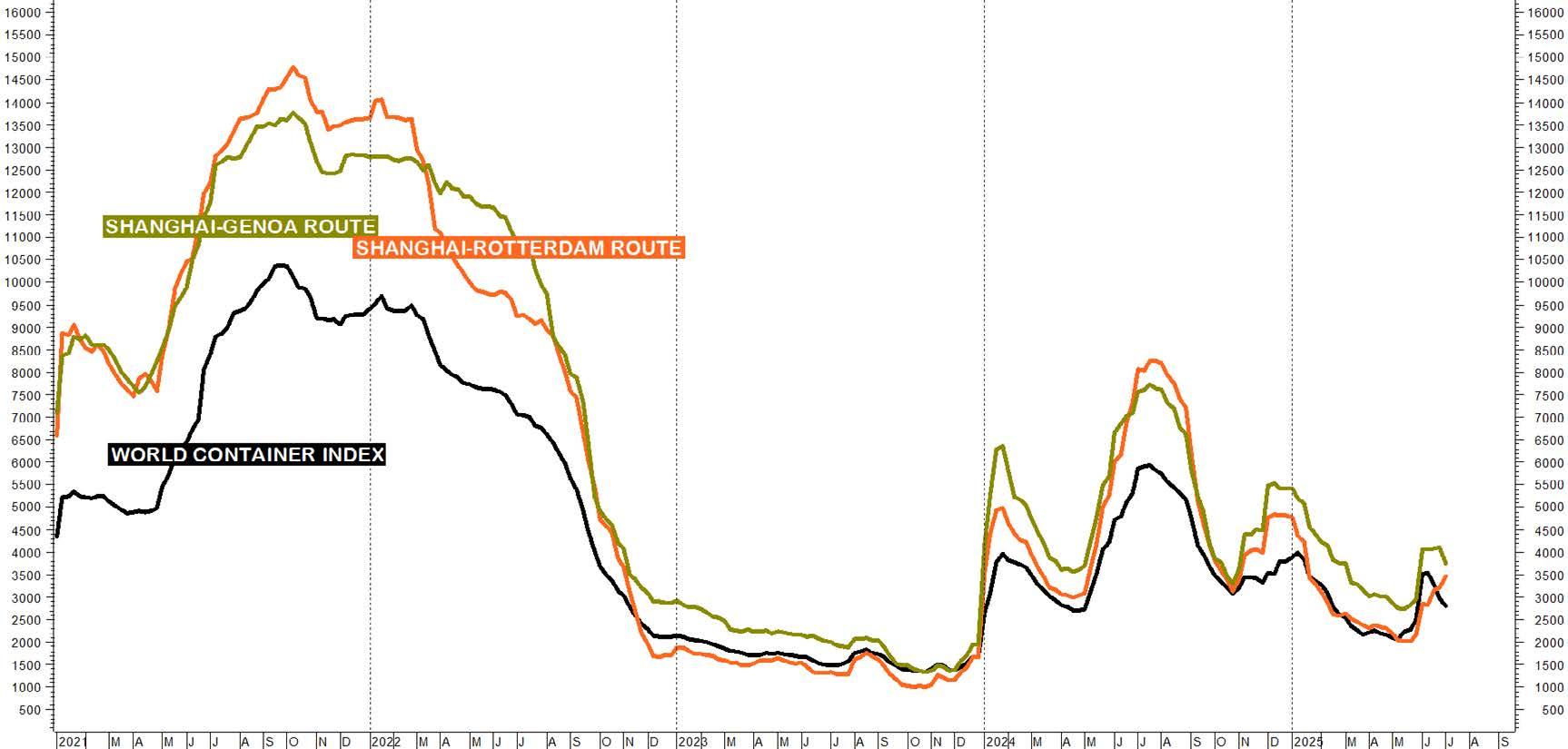
La stagnazione dell’economia globale si riflette nella stazionarietà dei mercati dell’energia e delle commodity industriali come si evince dalla figura 2. Una stabilità che non riguarda solo i tre aggregati di materie prime rappresentati nel grafico, ma anche le singole categorie merceologiche. Si segnalano peraltro due aspetti particolari: il primo riguarda le fonti energetiche, i cui prezzi finanziari sono dapprima stati sottoposti all’alta volatilità innescata dall’escalation della cosiddetta guerra dei 12 giorni in Medio Oriente e dalla susseguente de-escalation: la tensione ha infatti portato il prezzo del petrolio Brent fino a 80 $/
barile nelle quotazioni intraday per poi rientrare su valori intorno ai 70 dollari. La performance semestrale (-2,4%) riesce dunque a celare il picco, che ha riguardato anche le quotazioni del gas naturale. Gli altri aggregati si pongono in controtendenza: mentre il complesso dei metalli esprime un debole rialzo (+7,5%) - peraltro ancora guidato da preziosi come l’oro, l’argento e il platino - l’insieme dei beni agro-alimentari conferma la debolezza congiunturale (-10,2%) pur in presenza della veloce svalutazione del dollaro intervenuta nel mese di giugno, che rende le commodity quotate in dollari più convenienti per i Paesi detentori di altre valute.
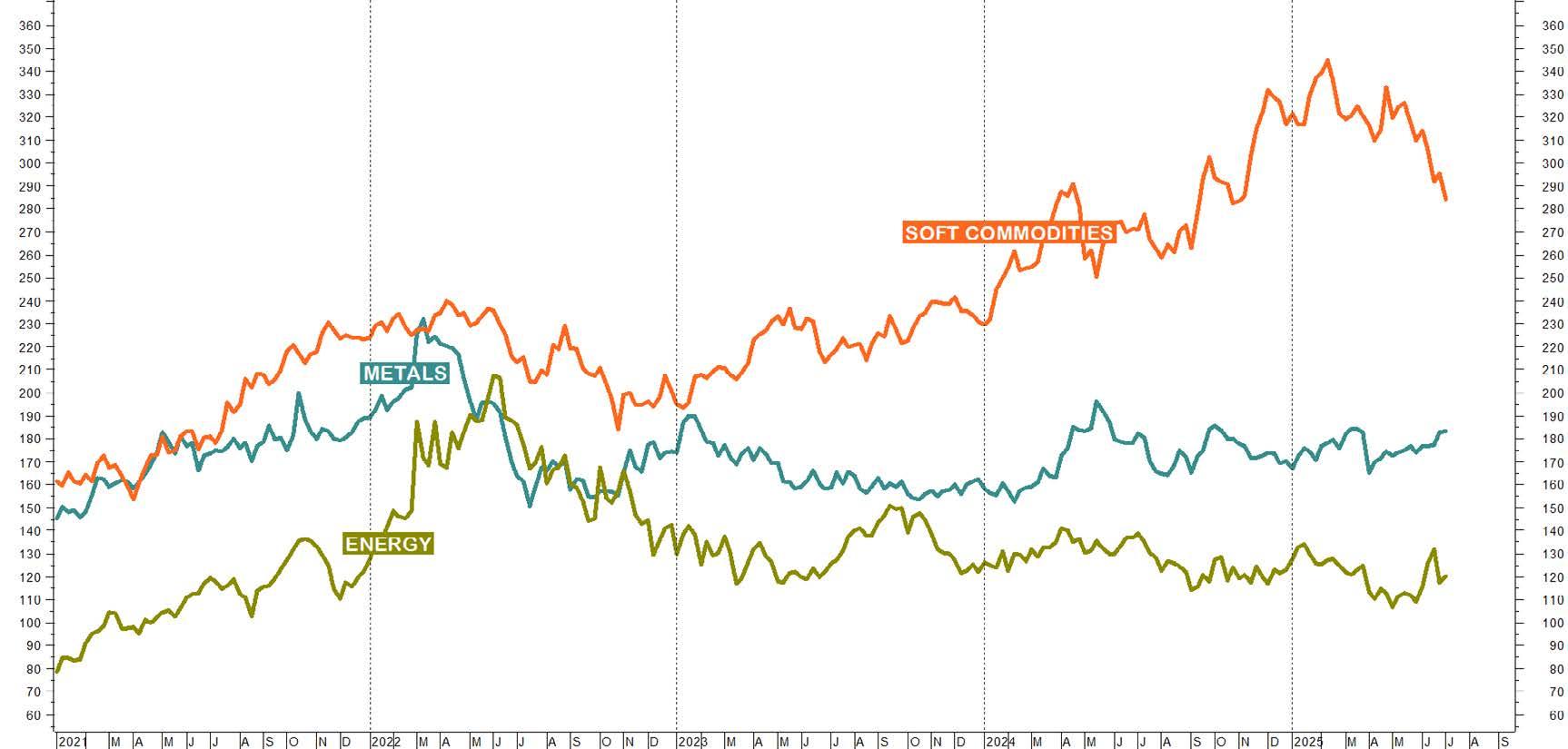
- L’evoluzione delle materie prime.
Acciaio e metalli: dinamiche, cicli e tendenza di mercato
La filiera della produzione di acciaio a ciclo integrale continua a soffrire gli effetti di una domanda in contrazione a causa della depressione dei principali comparti utilizzatori: l’edilizia, la meccanica e soprattutto l’Automotive. Si consideri la figura 3, che illustra non solo gli andamenti dei prezzi medi settimanali in US$/ton. del minerale di ferro (scala di destra) e del coke (scala a sinistra), ma altresì la loro sintesi ideale rappresentata dal valore teorico del valore di carica d’altoforno “core”, ovvero limitato al solo contributo ponderato dei due elementi fondamentali (scala di destra). Le dinamiche sono in calo dal mese di gennaio 2024: nel primo semestre di quest’anno le performance del minerale (-5,2%) e del coke (-12,4%) confermano la caduta degli acquisti soprattutto da parte della Cina sulla quale continua a pesare una crisi da iperproduzione da ciclo integrale che non trova sbocchi sul mercato interno. Nello stesso periodo il valore di carica sintetizza i
cali degli elementi fondamentali (-5,7%), sebbene inizino a formarsi reazioni di mercato tali da far presagire l’avvio di consolidamenti laterali dei prezzi, Gli esiti semestrali basilari trovano coerente riscontro nelle performance dei principali mercati delle produzioni a ciclo integrale (tabella 1), come dimostrano anche le dinamiche comprese nella figura 4 dedicata alle curve dei prezzi medi in US$/ton. dei coils a caldo internazionali. Mentre le dinamiche dei primi due mercati si mantengono in calo per l’intero semestre, nello stesso periodo la curva del mercato americano si impenna per poi assestarsi sui massimi: i timori di una carenza di offerta hanno infatti provocato quella corsa agli approvvigionamenti preventivi che ha determinato la performance in significativa controtendenza. Più in generale prosegue la pressione deflazionistica sui mercati provocata dal surplus produttivo cinese smaltito attraverso l’export nel resto del mondo.
COILS A CALDO INTERNAZIONALI ESITO 1° SEMESTRE 2025
FOB Shanghai -5,5%
FOB Black Sea -10,0%
CIF Houston +15,6%
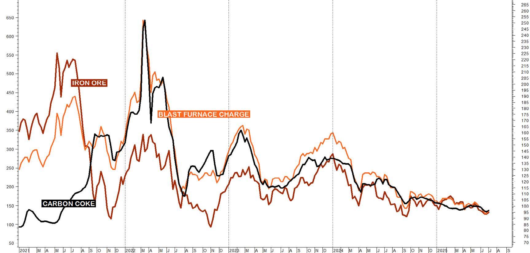
Fig.3 - Gli elementi basilari del ciclo integrale dell’acciaio.
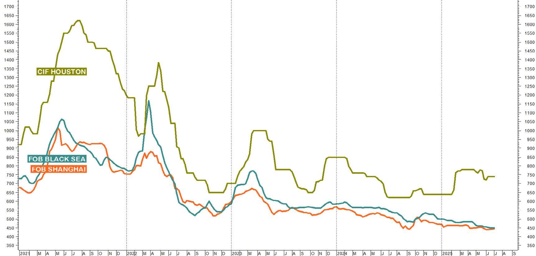
Fig.4 - I mercati internazionali dei coils.
La figura 5 e la tabella 2 confermano come nella prima metà dell’anno i mercati nazionali si presentino depressi, allineandosi agli esiti internazionali. Dal grafico si evince come il complesso dei piani abbia espresso un recupero durante l’intero primo trimestre per poi orientarsi decisamente al ribasso sostenuto solo, occasionalmente, dalle azioni di ri-stoccaggio volte a compensare esigenze produttive di brevissimo termine.
PRODOTTI PIANI NAZIONALI
ESITO 1° SEMESTRE 2025
Coils a caldo -1,2%
Lamiere nere -0,9%
Lamiere zincate +0,2%
Lamiere da treno
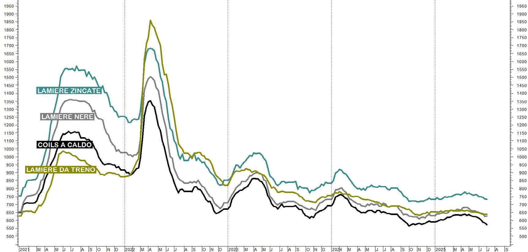
- Il mercato nazionale dei prodotti piani.
Acciaio e metalli: dinamiche, cicli e tendenza di mercato
In campo elettro-siderurgico si analizza dapprima l’andamento del rottame ferroso al quale è dedicata la figura 6, comprendente le dinamiche in euro/ton. dei prezzi per resa CFR Turkey e della media delle quotazioni di varie tipologie di rottame - frantumato, da demolizioni, torniture e lamierino - rilevate da Siderweb a livello nazionale. Si possono osservare due fasi dinamiche: dopo un intero primo trimestre orientato al rialzo, il prezzo del rottame quotato in Turchia, da considerarsi il principale benchmark europeo, si volge decisamente al ribasso raggiungendo in aprile livelli che non si osservavano dal mese di dicembre 2020, estendendo dunque la tendenza declinante avviatasi nel mese di marzo 2022 in occasione dello scoppio del conflitto russo-ucraino. La performance del primo semestre si consolida a -11,3% dopo un breve rim-
balzo subito spentosi tra i mesi di maggio e giugno. La media del rottame nazionale mostra invece un andamento oscillatorio orientato lateralmente pur rispettando la concordanza leggermente sfasata temporalmente rispetto alla dinamica seguita dal rottame di origine turca.
La performance semestrale (+3,4%) evidenzia come la tenuta dei prezzi della materia prima si riscontri anche tra i prodotti lunghi nazionali (figura 7) con l’unica eccezione del tondo per cemento armato, le cui quotazioni sprofondano nel secondo trimestre (tabella 3): un eccesso ribassista che il mercato dovrebbe correggere già a partire dal prossimo autunno.
Tondo per cemento armato
-10,8%
Vergella da rete +1,1%
Vergella da trafila -1,1%
Laminati mercantili -2,5%
Travi HEB S275 -2,0%
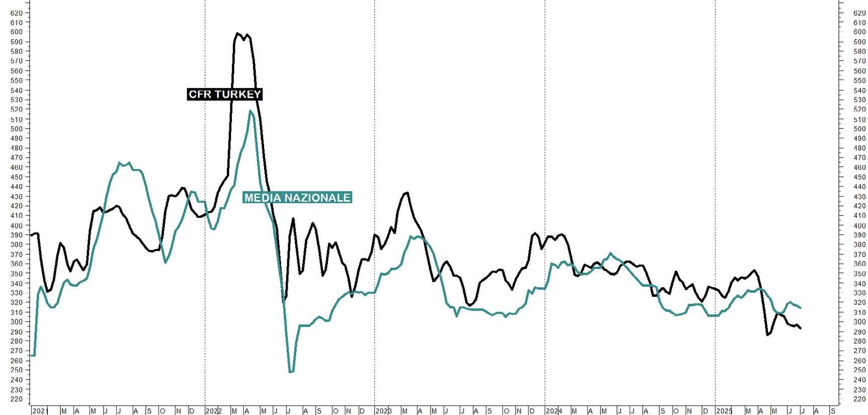
Fig.6 - Le quotazioni dei rottami ferrosi.
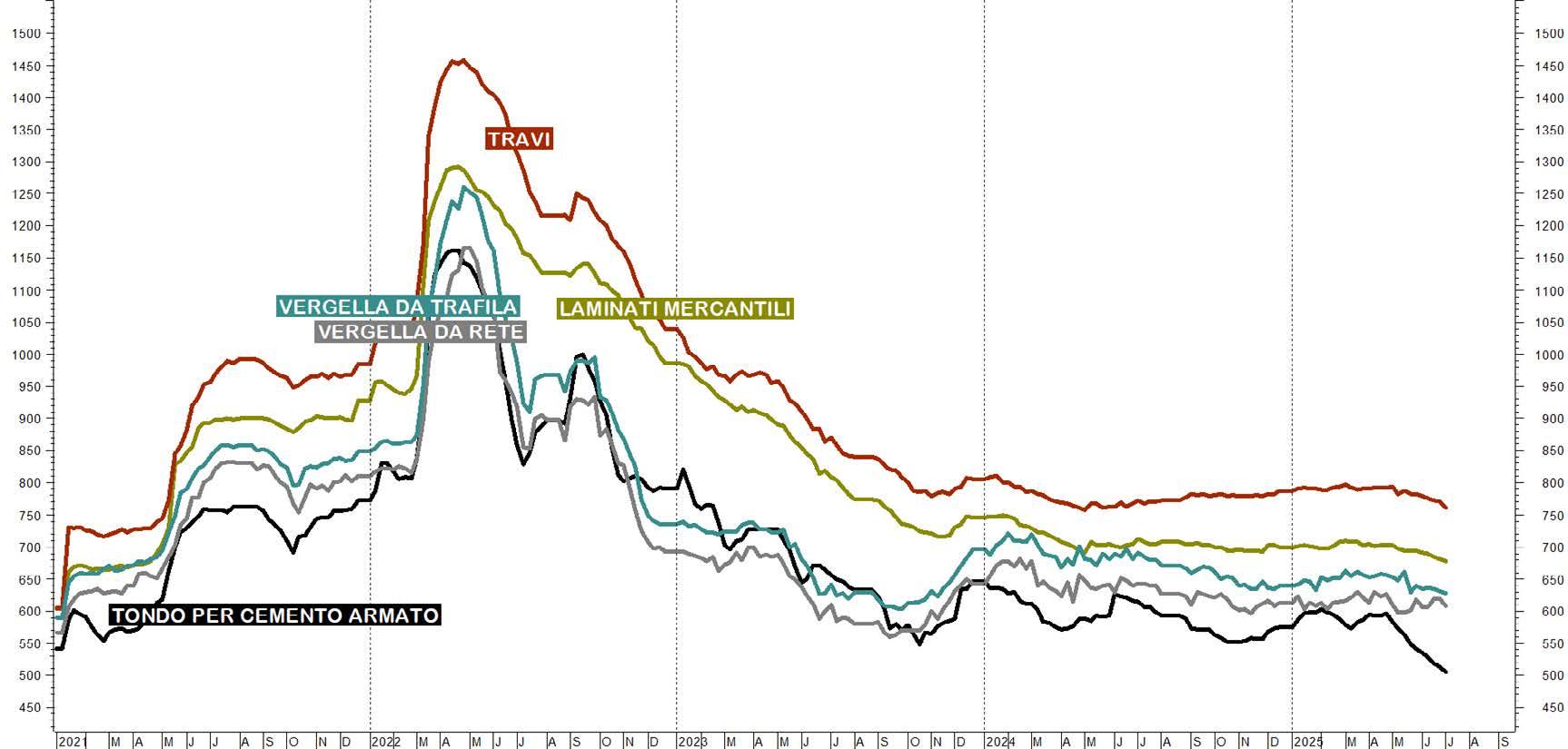
In continuità con le precedenti analisi, la figura 8 presenta la dinamica dei metalli non ferrosi derivata dalla media aritmetica semplice delle quotazioni medie settimanali dei prezzi in US$/ton dell’Alluminio, del Rame, del Nickel, dello Zinco, del Piombo e dello Stagno quotati al London Metal Exchange (scala di destra). Sovrapposto alla curva di mercato si osserva l’istogramma della contestuale evoluzione delle scorte fisiche complessive detenute presso i magazzini ufficiali del mercato londinese (scala di sinistra). Lo sviluppo semestrale del mercato attraversa tre fasi: dopo un primo rialzo avviatosi a inizio anno e spentosi a fine marzo (+15%), la curva di sintesi storna in aprile (-10,2%) per poi recuperare e chiudere la prima metà dell’anno a +10,2%. A sostenere quest’ultimo movimento la contrazione delle scorte ufficiali (-35%), che conferma il
ritorno agli acquisti della maggior parte dei metalli. Il comparto dei non ferrosi evidenzia dinamiche di mercato differenziate (tabella 4), orientate dalle distorsioni e dalla variabilità provocate dell’ondivaga incombenza dei dazi statunitensi: mentre lo stagno reagisce alla carenza di offerta, la minaccia di dazi ha spinto gli operatori ad accumulare scorte di rame negli Stati Uniti, determinando un repentino rialzo dei prezzi per effetto del drastico calo delle scorte disponibili al ritiro fisico sul mercato londinese. Nonostante l'incertezza sulla domanda globale, l'offerta di taluni metalli si profila in diminuzione come conseguenza dei diffusi blocchi produttivi: sebbene non siano previsti forti trend rialzisti, è altamente probabile che buona parte dei metalli industriali, sostenuta anche dal deprezzamento del dollaro statunitense, sia destinata a chiudere l’anno su livelli mediamente superiori a quelli correnti.
Acciaio e metalli: dinamiche, cicli e tendenza di mercato

- I metalli non ferrosi quotati al London Metal Exchange.
L’analisi del settore siderurgico inizia, come di consueto, valutando la figura 9, che presenta le dinamiche dei prezzi medi settimanali in euro/ton. del rottame inox (scala di sinistra), efficiente barometro di mercato, e del nickel, ingrediente basilare in talune tipiche produzioni in acciaio inossidabile. L’andamento dei due mercati appare altamente correlato al ribasso con esiti semestrali negativi: -12% il nickel con scorte in significativo aumento (+25,3%), -9,4% il rottame. Performance che ben rappresentano lo stato della domanda sottile che penalizza il comparto da oltre un triennio. L'analisi dei consumi esercitata da Siderweb mostra una dinamica disomogenea:
mentre si mantengono positivi i segnali provenienti dai settori alimentare, medicale e chimico, la maggiore sofferenza proviene dall’Automotive, dalle costruzioni e dagli elettrodomestici. Inoltre, mentre l’Europa ristagna esprimendo una domanda al di sotto delle aspettative, l’Asia, guidata dall’India, conferma la crescita robusta del comparto. Il mercato statunitense, che aveva iniziato il 2025 in modo promettente, sta invece rallentando a causa dell'incertezza legata ai dazi. Nel momento in cui scrivo non vi è ancora nulla di certo: tutto è stato rimandato ad agosto e questo spiega la depressione che sta orientando i mercati, che attendono la conclusione delle trattative commerciali tra UE e Stati Uniti.

Steel and metals: market dynamics, cycles and trends
Anche le ferroleghe impiegate nelle produzioni di acciai speciali consolidano performance negative, chiudendo il semestre sui minimi pluriannuali: si consideri al riguardo la figura 10, comprendente gli andamenti dei prezzi medi settimanali in euro/ton. del Ferro-Cromo (scala di destra) e del Ferro-Molibdeno (scala di sinistra). EVntrambe le
ferroleghe - che unitamente al Nickel sono utilizzate nella produzione di prodotti piani e lunghi inox - chiudono il semestre in negativo: -7% il Ferro-Cromo, -8.8% il Ferro-Molibdeno. Un’altra conferma dello stato della domanda di prodotti inox, i cui effetti risalgono ovviamente l’intera filiera
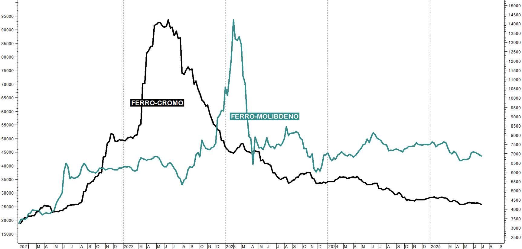
Fig.10 - I prezzi delle principali ferroleghe.
L’analisi del comparto inox si conclude considerando gli esiti semestrali di tipiche produzioni in acciaio inossidabile riportati nella tabella 5. Si tratta delle lamiere inox a freddo riferite alle tipologie stabilite dall’American Iron & Steel Institute: le lamiere di natura austenitica guidate, oltre che dal prezzo del rottame e del Nickel, dal Cromo (AISI 304) e dal Molibdeno (AISI 316), nonché le quotazioni delle lamiere di natura ferritica (AISI 430) prevalentemente
influenzate dalla dinamica del Ferro-Cromo. Se tali parametri attestano gli effetti della debolezza della domanda a valle della filiera inox, dalla terza settimana del mese di giugno emergono timidi segnali di risveglio: i rimbalzi dei prezzi delle lamiere a freddo AISI 430 (+1%) e del rotolo a caldo AISI 304 (+1,4%) delineano infatti l’esaurimento dei trend declinanti e l’avvio, quantomeno, di fasi di consolidamento motivate dal blando ritorno della domanda.
Tab.5
LAMIERE IN ACCIAIO INOSSIDABILE ESITO 1° SEMESTRE 2025
AISI 304 a freddo -5,0%
AISI 304 a caldo -1,3%
AISI 316 a freddo -3,6%
AISI 430 a freddo -1,8%
Acciaio e metalli: dinamiche, cicli e tendenza di mercato
Mentre scrivo lo scenario delineato dall’azione di Trump è ancora incerto, ma foriero di preoccupazioni: fino all’avvento di Trump i dazi sulle merci importate dall’Ue erano intorno al 2-3%, ma da aprile sono stati alzati al 10% (al 50% su acciaio e alluminio e al 25% sull’auto) e potenzialmente, al termine della «tregua» posticipata al 1° agosto, potrebbero arrivare al 50%. Un quadro davvero complicato per prevederne a breve gli sviluppi. La politica di Trump è spiccatamente imprevedibile nella strumentalizzazione dei dazi come strumento di pressione per ottenere concessioni su accordi commerciali o politici. Qualora non fossero raggiunte intese condivise entro breve tempo si
correrebbe il rischio di innescare vere e proprie guerre commerciali con ripercussioni negative per tutti i partecipanti. L'aggressiva agenda tariffaria, inoltre, rischia di isolare gli Stati Uniti da mercati globali vitali e potrebbe accelerare la formazione di blocchi commerciali regionali che offrono maggiore stabilità politica, mettendo a dura prova le relazioni con alleati importanti. In definitiva, l'attesa dei dazi di Trump crea un clima di profonda incertezza che si traduce in maggiore volatilità dei mercati, pressioni inflazionistiche, rallentamento della crescita economica e tensioni nelle relazioni commerciali internazionali, rendendo difficile alle imprese assumere decisioni strategiche..
Per le domande e i sempre graditi confronti: : achille.fornasini@unibs.it
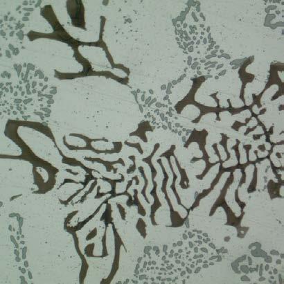

Corso METALLOGRAFIA MODULO 2
ALLUMINIO, TITANIO, RAME, MAGNESIO Genova, 16-17 settembre, 1 ottobre 2025
>> SCOPRI DI PIÙ
Corso itinerante
METALLURGIA SICURA
Lecco c/o Caleotto, 25 settembre 2025
Pozzuolo del Friuli c/o ABS Acciaierie Beroli Safau, 2 ottobre 2025
Vicenza c/o AFV Acciaierie Beltrame, 16 ottobre 2025
Corso
LE PROVE MECCANICHE NEL SETTORE METALLURGICO: STRUMENTI, METODOLOGIE ED APPROCCI APPLICATIVI
Milano, Pozzo d'Adda c/o S.M.T., Castel San Giovanni c/o Sider Test17-18 settembre e 1-2 ottobre 2025
>> SCOPRI DI PIÙ
Giornata di Studio
CARATTERISTICHE E DIAGNOSTICA DEI PRODOTTI IN COMPOSITO TRA INDUSTRIA E TEMPO LIBERO Milano, 2 ottobre 2025
>> SCOPRI DI PIÙ
7th European Steel Technology and Application Days 2025
7th ESTAD 2025
Verona - Palaexpo VeronaFiere - 6-9 October 2025
>> SCOPRI DI PIÙ

Corso di base LEGHE DI ALLUMINIO
Milano + webinar, 28-29 ottobre 2025
Giornata di Studio DONNE IN METALLURGIA: UNA RISORSA PER IL FUTURO Brescia c/o AIB - 29 ottobre 2025
>> SCOPRI DI PIÙ
Giornata di Studio MATERIALI PER IL NUCLEARE. SFIDE E OPPORTUNITÀ Terni, 3-4 novembre 2025
>> SCOPRI DI PIÙ
DTMI 2025 - International Workshop ing. Carlo Longaretti on Digital Tools for the Metallurgical Industry Bergamo - 27-28 November 2025
>> SCOPRI DI PIÙ
EEC 2026 - EMECR 2026 Conferences 4th European Electric Steelmaking conference & 5th International Conference on Energy and Material Efficiency and CO2 Reduction in the Steel Industry Brescia - 11-13 May 2026
>> SCOPRI DI PIÙ
WCCM 2026
The 4th World Congress on Condition Monitoring Milano - Italy - 25-28 August 2026
Il Centro di Studio è stato costituito nel 2001 con lo scopo di favorire lo sviluppo delle conoscenze tecniche e tecnologiche della Pressocolata Italiana. In particolare, vengono elaborate iniziative di formazione e di divulgazione scientifica su aspetti di interesse per il settore, con attenzione ai temi del risparmio energetico, della sostenibilità ambientale, dell’utilizzo di nuove leghe e di quelle a bassa impronta carbonica. La metallurgia dei getti, la classificazione dei difetti e le linee guida per evitarli, così come la scelta degli acciai per gli stampi e utensili, le tecnologie innovative di produzione e di digitalizzazione della stessa, fanno parte degli argomenti oggetto di studio e di divulgazione.


Presidente: Piero Parona
Vicepresidente: Giulio Timelli
Segretario: Roberto Martina
Il CTP è costituito da una trentina di membri che con continuità contribuiscono alla discussione ed elaborazione di proposte formative e di divulgazione tecnica.
Uno dei punti di forza del Comitato è la presenza al suo interno di persone con competenze consolidate, appartenenti a tutta la filiera del processo manifatturiero. Ciò significa la presenza di rappresentanti delle fonderie, dei costruttori di presse, dei produttori di stampi, dei raffinatori di leghe di Alluminio, dei produttori di acciai per stampi, dei fornitori di trattamenti termici, di lubrificanti e di attrezzature periferiche quali centraline di termoregolazione, di sistemi di lubrificazione e di sistemi di monitoraggio delle temperature degli stampi. Ad essi si aggiungono alcuni docenti universitari di Metallurgia ed esperti di simulazione numerica dei processi di colata, di solidificazione, di trattamento termico e di analisi strutturale. Grazie a questo ampio ventaglio di competenze è possibile garantire un aggiornamento costante delle proposte al passo con l’evoluzione del mercato e delle sue tendenze. Parlando di evoluzione del mercato è necessario sottolineare come il settore della fonderia di pressocolata stia attraversando un momento di grande incertezza, dovuta a una graduale riduzione dei volumi
di produzione, principalmente derivata dalla crisi del settore automotive e ad un contemporaneo aumento dei costi dell’energia che grava sulle fonderie Italiane. In un “mare burrascoso” come questo, il CTP ha cercato di adeguare le proprie proposte, offrendo iniziative sia in presenza, che in modalità webinar e duale, che cogliessero spunti dall’attualità.
Fra le attività recentemente svolte troviamo le Giornate di Studio “Getti pressocolati per applicazioni strutturali” ospitate presso IDRA e al Museo delle Mille Miglia di Brescia; il Webinar “Emergenza costi energetici: cosa fare in fonderia” conclusosi con una Tavola Rotonda con alcuni imprenditori di fonderia; la Giornata di Studio “Innovazione e digitalizzazione in Pressocolata: verso il futuro della produzione” al termine della quale si è svolta una Tavola Rotonda moderata da Tiziana Tronci dal titolo “Digitalizzare conviene”, animata da un intenso di battito fra alcuni titolari di azienda ed esperti di digitalizzazione industriale e innovazione.
Nell’autunno del 2025 è prevista l’attivazione del terzo “Master Progettazione Stampi”. Il Master nasce con l’intenzione di fornire le conoscenze più aggiornate per la progettazione degli stampi da pressocolata ed è rivolto a tecnici che operano nel settore della progettazione,
realizzazione e utilizzo di stampi da pressocolata. Gli argomenti trattati rappresentano, ad oggi, conoscenze che sono solitamente patrimonio di poche persone e non sempre degli addetti all’ufficio tecnico delle fonderie. Il Master, pur mantenendo ampio spazio per le esercitazioni pratiche (32 ore), in cui i partecipanti stessi saranno chiamati a confrontarsi direttamente nella progettazione delle varie componenti stampo, si propone di dare rilevanza a temi estremamente specifici, ma essenziali per le tecnologie di pressocolata più avanzate. Il Master si sviluppa su quindici giornate suddivise per aree tematiche che ripercorrono quasi idealmente il flusso del metallo in fase di colata, e vuole dare tutti gli elementi tecnici per formare personale in grado di seguire l’intero processo di progettazione di
uno stampo e delle sue attrezzature.
Un tema di attualità sul quale il CTP sta lavorando, è la comparsa sul mercato dei cosiddetti megacasting e gigacasting. Questa tipologia di getti rappresenta una rivoluzione per le dimensioni degli stessi e per le attrezzature di produzione. Con questa tipologia di getti si possono ottenere notevoli risparmi nell’assemblaggio del telaio delle auto e questo sta suscitando un ampio dibattito sui pro e contro legati alla loro adozione. Gli aspetti coinvolti sono molteplici e il Comitato ritiene utile proporre un’iniziativa nella quale si mettano a confronto le diverse opinioni e tendenze, come ad esempio quelle fra i costruttori Cinesi e quelli Europei.
Norme pubblicate e progetti in inchiesta (aggiornamento al 30 giugno 2025)
Norme UNSIDER pubblicate da UNI nel mese di giugno 2025
UNI EN ISO 23779:2025
Macchine granigliatrici - Requisiti di sicurezza e ambientali
UNI EN ISO 2477:2025
Prodotti refrattari isolanti formati - Determinazione della variazione permanente delle dimensioni dovuta al riscaldamento
Norme UNSIDER ritirate con sostituzione da UNI nel mese di giugno 2025
UNI EN 1248:2009
Macchine da fonderia - Requisiti di sicurezza per apparecchiature di granigliatura
UNI EN 1094-6:2000
Prodotti refrattari isolanti - Determinazione della variazione permanente delle dimensioni dei prodotti formati dovuta al riscaldamento
Norme UNSIDER pubblicate da CEN e ISO nel mese di giugno 2025
EN ISO 14723:2025
Oil and gas industries including lower carbon energy - Pipeline transportation systems - Subsea pipeline valves (ISO 14723:2025)
EN ISO 15630-3:2025
Steel for the reinforcement and prestres-
sing of concrete - Test methods - Part 3: Prestressing steel (ISO 15630-3:2025)
ISO 15630-3:2025
Steel for the reinforcement and prestressing of concrete — Test methods — Part 3: Prestressing steel
ISO 14723:2025
Oil and gas industries including lower carbon energy — Pipeline transportation systems — Subsea pipeline valves
ISO 14313:2025
Oil and gas industries including lower carbon energy — Pipeline transportation systems — Pipeline valves
ISO 13503-8:2025
Oil and gas industries including lower carbon energy — Completion fluids and materials — Part 8: Measurement of properties of coated proppants used in hydraulic fracturing
ISO 12747:2025
Oil and gas industries including lower carbon energy — Pipeline transportation systems — Requirements and guidance for pipeline life extension assessment
Progetti UNSIDER messi allo studio dal CEN (Stage 10.99) – luglio 2025
prEN ISO 28300 rev
Petroleum, petrochemical and natural gas industries – Venting of atmospheric and low-pressure storage tanks
prEN ISO 24202
Oil and gas industries including lower carbon energy – Bulk material for offshore projects — Monorail beam and padeye
prEN ISO 3845
Oil and gas industries including lower carbon energy – Full ring ovalization test method for the evaluation of the cracking resistance of steel line pipe in sour service
prEN ISO 24817 rev
Petroleum, petrochemical and natural gas industries – Composite repairs for pipework — Qualification and design, installation, testing and integrity management
prEN ISO 14577-5
Metallic materials – Instrumented indentation test for hardness and materials parameters – Part 5: Linear elastic dynamic instrumented indentation testing (DIIT)
prEN ISO 26203-3
Metallic materials – Tensile testing at high strain rates – Part 3: Test method at elevated temperature
Progetti UNSIDER in inchiesta prEN e ISO/DIS – luglio 2025
prEN – progetti di norma europei
prEN ISO 13680
Oil and gas industries including lower carbon energy - Corrosion-resistant alloy seamless products for use as casing, tubing, coupling stock and accessory material - Technical delivery conditions (ISO 13680:2024)
ISO/DIS – progetti di norma internazionali
ISO/DIS 657-1
Hot-rolled steel sections — Dimensions,
sectional properties and tolerances — Part 1: Angles, channels and beams
Progetti UNSIDER al voto FprEN e ISO/FDIS – luglio 2025
FprEN – progetti di norma europei
FprEN 12680-2
Founding - Ultrasonic testing - Part 2: Steel castings for highly stressed components
FprEN 12680-1
Founding - Ultrasonic testing - Part 1: Steel castings for general purposes
FprEN 12680-3
Founding - Ultrasonic testing - Part 3: Spheroidal graphite cast iron castings
FprEN ISO 10280
Steel and iron - Determination of titanium content - Diantipyrylmethane spectrophotometric method (ISO/FDIS 10280:2025)
ISO/FDIS – progetti di norma internazionali
ISO/FDIS 10280
Steel and iron — Determination of titanium content — Diantipyrylmethane spectrophotometric method
International Conference on Energy and Material Efficiency and CO2 Reduction in the
www.aimnet.it/eec2026
EEC 2026 & EMECR 2026 will be jointly held by AIM, Italian Association for Metallurgy, in Brescia on 11-13 May 2026!
The 14th European Electric Steelmaking conference (EEC 2026) will cover a wide range of topics related to the production of steel using electric arc furnaces (EAFs) and other electric-based processes.
Steel manufacturers and producers, Equipment suppliers and technology providers, Researchers and academics, Policy makers and regulators, Environmental consultants, Industry analysts and investors will be able to meet and share knowledge and best practices, identify new research areas and collaboration opportunities, develop strategies to address industry challenges and promote sustainable and efficient electric steelmaking practices.
The first EMECR was held in 2011 in Germany, followed by UK in 2014, Japan in 2017 and Brazil in 2022. Thanks to these successful events, the EMECR has become a recognized forum for high level discussions on environmental related topics such as CO2 reduction, materials efficiency and product life cycles in the steel industry worldwide.
EEC 2026 & EMECR 2026 will provide opportunities for networking with industry leaders, researchers, and policymakers, discussing collaborative projects and partnerships.
EEC 2026 & EMECR 2026 comprehensive scope ensures that the conference addresses the current challenges and future opportunities in the steelmaking industry, fostering innovation and sustainability.
The Conferences will be enriched with an exhibition, where sponsors will be able to display new technologies and equipment.