Italiana La Metallurgia
International Journal of the Italian Association for Metallurgy
n. 04 aprile 2024
Organo ufficiale dell’Associazione Italiana di Metallurgia. Rivista fondata nel 1909


International Journal of the Italian Association for Metallurgy
n. 04 aprile 2024
Organo ufficiale dell’Associazione Italiana di Metallurgia. Rivista fondata nel 1909
International Journal of the Italian Association for Metallurgy
Organo ufficiale dell’Associazione Italiana di Metallurgia. HouseorganofAIMItalianAssociationforMetallurgy. Rivista fondata nel 1909
Direttore responsabile/Chiefeditor: Mario Cusolito
Direttore vicario/Deputydirector: Gianangelo Camona
Comitato scientifico/Editorialpanel: Marco Actis Grande, Silvia Barella, Paola Bassani, Christian Bernhard, Massimiliano Bestetti, Wolfgang Bleck, Franco Bonollo, Irene Calliari, Mariano Enrique Castrodeza, Emanuela Cerri, Vlatislav Deev, Andrea Di Schino, Donato Firrao, Bernd Kleimt, Carlo Mapelli, Denis Jean Mithieux, Roberto Montanari, Marco Ormellese, Mariapia Pedeferri, Massimo Pellizzari, Barbara Previtali, Evgeny S. Prusov, Dario Ripamonti, Dieter Senk
Segreteria di redazione/Editorialsecretary: Marta Verderi
Comitato di redazione/Editorialcommittee: Federica Bassani, Gianangelo Camona, Mario Cusolito, Carlo Mapelli, Federico Mazzolari, Marta Verderi, Silvano Panza
Direzione e redazione/Editorialandexecutiveoffice: AIM - Via F. Turati 8 - 20121 Milano tel. 02 76 02 11 32 - fax 02 76 02 05 51 met@aimnet.it - www.aimnet.it
Reg. Trib. Milano n. 499 del 18/9/1948. Sped. in abb. Post. - D.L.353/2003 (conv. L. 27/02/2004 n. 46) art. 1, comma 1, DCB UD
Immagine in copertina: Prof. Massimo Pellizzari.

Gestione editoriale e pubblicità Publisher and marketing office: siderweb spa sb Via Don Milani, 5 - 25020 Flero (BS) tel. 030 25 400 06 - fax 030 25 400 41 commerciale@siderweb.com - www.siderweb.com
La riproduzione degli articoli e delle illustrazioni è permessa solo citando la fonte e previa autorizzazione della Direzione della rivista. Reproduction in whole or in part of articles and images is permitted only upon receipt of required permission and provided that the source is cited.
siderweb spa sb è iscritta al Roc con il num. 26116
n.04 aprile 2024
Anno 115 - ISSN 0026-0843
Editoriale / Editorial
A cura di prof.Massimo Pelizzari . pag.05
Memorie scientifiche / Scientific papers
Trattamenti Termici / Heat Treatment
A comparative study on Aluminum-Silicon coatings fabricated by ElectroSpark Deposition
G. Renna, P. Leo ................................................................................................................................................ pag.08
Nanocomposite Cr2N-Ag thin films for tribological applications at elevated temperatures
P. Jurci . pag.19
3D-printed 316 L stainless steel: optimization of low temperature plasma assisted carburizing
A. Palombi, R. Montanari, A. Varone, C. Verona, E. Bolli, S. Kaciulis, A. Mezzi, A. Lanzutti, F. Sordetti, E. Vaglio.. . pag.25
Characterization of AlCrN films deposited onto Selective Laser Melted Ti6Al4V substrates
E. Cerri, E. Ghio, G. Bolelli, A. Bertè, P. Colombi .............................................................................................................. pag.32
Characterization of T5 and T6 heat treatment on high end-of-life-scrap secondary aluminium alloy for High-Pressure-Die-Casting automotive structural component
E. Ferrari, S. Gaiani, M. Gozzi, M. T. Di Giovanni, M. Lassinantti Gualtieri, F. Mantovani, G. Ponzoni, P. Veronesi ... pag.38
Comparison of As Cast and T6 heat treatment on high end-of-life-scrap secondary aluminium alloy for High-Pressure Die Casting automotive structural components
A. Bongiovanni, A. Castellero, M. Da Silva pag.50
Scenari / Experts' Corner
Artificial Intelligence techniques supporting Heat Treatment processes
I. Felde ........................................................................................................................................................................................................... pag.58
Atti e notizie / AIM news
MCHTSE and TPMS-5 Conferences Recap pag.63 Eventi AIM / AIM events pag.66 Comitati tecnici / Study groups ........................................................................................... pag.68
Normativa / Standards ......................................................................................................... pag.70

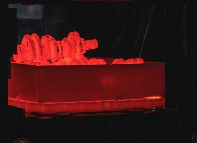
AIM and Federacciai proudly announce that the 22nd International Forgemasters Meeting will be held in Italy in 2024.
All involved in and interested in the area of open die forging and ring rolling are warmly invited to attend.
IFM is a unique forum to meet researchers, skilled technicians and decision makers; in other words IFM 2024 is an unmissable event for the forging industry!
Over 140 oral and poster papers will define the latest developments in open die forging and ring rolling over 3 days of presentations. Full information on programme, planned planned tours and registration are available at www.ifm2024.org
Four technical visits are scheduled in the morning of May 30th:
FOMAS in Osnago, Lecco - Italy
FORGE MONCHIERI in Cividate Camuno, Brescia - Italy
IRE-OMBA in Bergamo, Italy
. OFAR in Canneto Sull’Oglio, Mantova - Italy
In order to be considered for one of the proposed plant tours, delegates should apply early and must receive an approval to participate by the Organizing Secretariat.
Organised by in cooperation with
Sponsored by
Supported by

"Più che in passato, risulterà decisiva la capacità delle aziende di innovare, per trasformare potenziali fonti di criticità in vere e proprie opportunità. "
“More than in the past, theabilityofcompaniesto innovate will be decisive in turningpotentialsources ofcriticalityintoreal opportunities.”
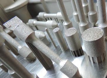
Come molti altri settori produttivi, anche quello dei trattamenti termici (nel senso più ampio del termine, comprendente i trattamenti superficiali ed i rivestimenti) sta vivendo una fase di importanti cambiamenti e, conseguentemente, di grandi sfide. Un primo obiettivo è certamente quello legato alla sostenibilità, ovvero alla riduzione dei consumi energetici e delle emissioni. Alcuni produttori di forni, ad esempio, hanno già introdotto modifiche tecniche per consentire l’utilizzo di differenti fonti energetiche e fare così fronte ad oscillazioni dell’offerta e dei conseguenti costi. Un secondo tema caldo è quello relativo ai trattamenti termici di nuovi materiali, come quelli prodotti per manifattura additiva, quelli legati al lightweight design per il settore automobilistico, aeronautico ed aerospaziale. Nel campo delle tecnologie additive si sta procedendo nella direzione del trattamento termico in-situ, durante il processo di stampa, grazie all’utilizzo di macchine con più sorgenti laser. Un terzo tema di grande attualità è rappresentato dalla digitalizzazione, della modellazione di processo,
Like many other manufacturing sectors, the heat treatment sector (in the broadest sense of the term, including surface treatments and coatings) is undergoing a phase of major changes and, consequently, major challenges. A first goal is certainly one related to sustainability, that is, the reduction of energy consumption and emissions. Some furnace manufacturers, for example, have already introduced technical changes to allow the use of different energy sources and thus cope with fluctuations in supply and consequent costs. A second hot topic is the heat treatment of new materials, such as those produced by additive manufacturing, those related to lightweight design for the automotive, aerospace, and aeronautics industries. In the field of additive technologies, progress is being made in the direction of in-situ heat treatment, during the printing process, through the use of machines with multiple laser sources. A third topical issue is digitization, process modeling, the push of artificial intelligence and possible fields of use in heat
dall’incalzare dell’intelligenza artificiale e dei possibili campi di impiego nei trattamenti termici. Probabilmente, più che in passato, risulterà decisiva la capacità delle aziende di innovare, per trasformare potenziali fonti di criticità in vere e proprie opportunità. In futuro, sarà importante sviluppare sinergie tra aziende, università, centri di ricerca mettendo a fattor comune conoscenze e competenze complementari. Le tecnologie digitali offrono opportunità poco sfruttate prima della pandemia (v. webinar, eventi online,…) ma per creare e rafforzare le reti di collaborazione è fondamentale continuare a coltivare i rapporti interpersonali attraverso la partecipazione in presenza ad eventi che vedono AIM, l’Associazione Italiana di Metallurgia, sempre in prima linea. Gli argomenti elencati sono diventati centro di una vera e propria missione per le associazioni categoria di tutto il mondo e anche di IFHTSE, l’International Federation for Heat Treatment and Surface Engineering, che da gennaio di quest’anno ho l’onore di guidare come primo presidente italiano. Argomenti ampiamente dibattuti nel corso delle due conferenze, 4th Mediterranean Conference on Heat Treatment and Surface Engineering - MCHTSE 2024 e 5th International Conference on Thermal Process Modeling and Simulation - TPMS-5, che si sono tenute a Lecce, dal 17 al 19 aprile. In questo numero della Metallurgia Italiana i lettori potranno trovare alcune delle memorie presentate, che mi auguro possano suscitare interesse e spunti per progetti futuri.
treatment.
Probably, more than in the past, the ability of companies to innovate will be decisive in turning potential sources of criticality into real opportunities. In the future, it will be important to develop synergies between companies, universities and research centres by pooling complementary knowledge and skills. Digital technologies offer opportunities that were little exploited before the pandemic (see webinars, online events,...), but to create and strengthen collaboration networks, it is essential to continue to cultivate interpersonal relationships through attendance at events in which AIM, the Italian Metallurgy Association, is always at the forefront.
The topics listed have become the focus of a real mission for industrial associations around the world and also for IFHTSE, the International Federation for Heat Treatment and Surface Engineering, which since January this year I have had the honour of leading as the first Italian president. These topics were widely debated during the two conferences, 4th Mediterranean Conference on Heat Treatment and Surface Engineering - MCHTSE 2024 and 5th International Conference on Thermal Process Modeling and Simulation - TPMS-5, held in Lecce, Italy, from 17 to 19 April. In this issue of Metallurgia Italiana, readers will find some of the papers presented, which I hope will generate interest and ideas for future projects.

(FC) | 30 JUNE - 1-2-3 JULY 2024
The Metallurgy Summer School Metal Additive Manufacturing, organized by CoMET, is the 2nd edition of the event. The first one (2020), held in Trento, focused the attention on the additive manufacturing (AM) techniques and general features of metals prepared in this way. On the basis of that experience and suggestions of participants, the scope of this school is to provide a deeper insight into advantages and problems arising in different types of metallic alloys.
After an introductory section devoted to present the state of art of AM metal processing, powder production, experimental techniques for part characterization, and simulations for predicting the mechanical properties of metals produced by AM, the lectures will treat the specific cases of several alloys of industrial interest. They include tool steels, FeSi alloys for electric applications, Ni base superalloys, Al alloys for aerospace and other applications, Ti alloys for “racing” and “aerospace, CoCr alloys, biodegradable Zn alloys and duplex stainless steels for biomedical uses, and metamaterials for nuclear sector. Trends and opportunities of design for AM, lattice and cellular structures (Auxetic and TPMS) with porosity gradient will be also presented and discussed. In conclusion, the program will provide an overview on current scientific and technological challenges.
The school is mainly addressed to PhD students of engineering, materials science, physics and chemistry and technical personnel from industry but post-docs and master students are also welcomed. The lectures, given by experts in the field, aim to stimulate exchange of ideas and favour future research cooperation of participants.
Termici e Metallografia organizza la XIX edizione del Corso modulare Trattamenti Termici in modalità ibrida, ovvero offrendo la possibilità di partecipare in presenza o da remoto.
I settori interessati ai trattamenti termici riguardano tutta l’industria meccanica, compresa quella auto moto veicolistica, dove molti organi trattati risultano di sicurezza e quindi occorre un’approfondita conoscenza della materia.
Moduli del Corso:
Modulo 0: Introduzione alla metallurgia di base per i trattamenti termici Milano, 8-9 maggio 2024 (anche in diretta streaming su Zoom)
Modulo 1: Trattamenti termici massivi e acciai inossidabili Milano, 15 maggio 2024 (anche in diretta streaming su Zoom)
Modulo 2: Trattamenti termici acciai da utensili e materiali da polvere
Milano, 16 maggio 2024 (anche in diretta streaming su Zoom)
Modulo 3: Trattamenti termici superficiali
Avigliana c/o Motivexlab, 22 maggio 2024 (anche in diretta streaming su Zoom)
Modulo 4: Norme e impianti
Avigliana c/o Motivexlab, 23 maggio 2024 (solo in presenza)
Modulo 5: Trattamenti termici leghe non ferrose Campogalliano c/o Tec Eurolab, 5 giugno 2024 (anche in diretta streaming su Zoom)
Modulo 6: Caratterizzazione, failure e CND Campogalliano c/o Tec Eurolab, 6 giugno 2024 (solo in presenza)

Intoday'sindustrialsector,thereisagrowinginterestineco-friendlypractices,alongwiththeessentialgoalofimproving the durability and resistance to wear and corrosion of mechanical components exposed to harsh environments by applying coatings. A key technology meeting these objectives is Electrospark Deposition (ESD), a micro-welding processthatallowselectricallyconductivesubstratestobecoatedwithdifferentmaterials.ESDalsofacilitatesprecise, small-scalerepairsofhigh-valuecomponentsdamaged,worn,oraffectedbymanufacturingdefects.
This study examines and compares the quality of A357 and C355 aluminium alloy coatings deposited on homologous substratesusingESDtechnology.Itfocusesonmicrostructuralcharacteristics,mechanicalproperties,andstereological features.
Three different discharge power levels were used to deposit coatings on both aluminium alloys. The cross-sectional coatings were examined using scanning electron and optical microscopy to analyse their microstructure and evaluate the coating quality in detail. Additionally, the mechanical properties of the coatings were assessed through Vickers microhardnesstesting.
The microstructural analysis indicates that irrespective of the discharge power employed, all coatings exhibit a very fine microstructural morphology attributed to rapid solidification. Furthermore, experimental findings reveal that all coatings exhibit defects, manifested in the form of various morphologies of voids. Additionally, unlike the A357 samples, the C355 samples display cracks at the interface between the substrate/coating, extending into the base material. The defects percentage within the A357 and C355 coatings, primarily attributed to mass transport and stress thermal, is less than 4 and 8%, respectively. Finally, microhardness values in all coatings, irrespective of discharge powersettings,arelowerthanthesubstratematerial.Thisisprimarilyattributedtothepresenceofinternaldefects.
KEYWORDS: ALUMINIUM ALLOYS, ELECTROSPARK DEPOSITION (ESD), MICROSTRUCTURE, COATINGS, C355 ALLOY, A357 ALLOY
In the aeronautical and automotive industries, the current trend to address fuel consumption and weight reduction issues is to use light metal alloys to produce various components as an alternative to traditional iron-based alloy components. Aluminium cast alloys are the preferred choice for these fields due to their good castability, strong corrosion resistance, and high strength-to-weight ratio [1,2]. Additionally, these alloys benefit from heat treatment, further enhancing their properties. At the industrial level, the most used Al alloys are A357 (belonging to the AlSi7Mg system) and C355 alloy (quaternary Al–Si–Cu–Mg alloy) which are usually processed by low-pressure die-casting and
Gilda Renna, Paola Leo
Department of Engineering for Innovation, University of Salento, Lecce gilda.renna@unisalento.it
gravity semi-permanent mold technology [3,4]. The A357 alloy properties depend on the distribution of the Mg and Si alloying elements in the Al matrix and the Mg2Si second-phase precipitates [5]. In the automotive field, it has found a variety of uses over the years to produce engine blocks such as cylinder heads, pistons, and brake callipers, while in aerospace have been made engine mounts in fighter planes and ailerons [6-8]. Instead, due to their high strength at high temperatures, the C355 alloy is found in the aircraft and automotive industry in the form of aircraft supercharger covers, fuel-pomp bodies, air-compressor pistons, liquid-cooled aircraft engine crankcases, motor mounts, cylinder heads, heat exchangers, air conditioners, transmissions housings, wheels, fenders, loads floor and suspension components [9].Ingeneral,duringsolidification,differentintermetallic phases can form in an Al-Si-Cu-Mg aluminium alloy (i.e C355 alloy), depending on its overall composition. The chemicalcomposition,relativefractionvolumeandshape (morphology) of these phases significantly influence the alloy's technological properties. However, to improve the mechanical properties and ductility, both alloys are generally heat-treated. The heat treatment consists of solution treatment, quenching and artificial ageing. After solution treatment and quenching, the Mg and Cu-rich intermetallic compounds dissolve into the Al matrix [912].
Generally, the mechanical components made with these alloys during their service life are subject to wear resulting from prolonged use and exposure to aggressive environments. Therefore, another challenge at an industrial level is to reduce the costs related to the replacement of damaged components. On the other hand,itisknownthatalargefractionofmaintenancecosts is due to the disassembly and transport of components where on-site repair is not possible. For these reasons, researchers and industries are placing a high level of attentiononthedevelopmentofinnovative,low-costand eco-friendly processes for applying coatings that can increase the component's resistance or restore damaged or worncomponents[13,14].
Nowadays,oneoftheprocessesabletosatisfytheabovementioned requirements is the Electrospark Deposition
(ESD). This is a micro-welding process used in the smallscale precision repair of high-value components that are damaged,worn,orhavemanufacturingdefects.Moreover, it also be used as a coating technique for electrically conductive substrates by depositing materials that are homologous or dissimilar to the substrate, to improve the surface mechanical or chemical properties of the substrate. In addition to the small size of the equipment, one of the advantages that distinguishes it from other traditional coating/repair processes is the reduced heat input induced in the substrate. Several researches show that the ESD process can originate an excellent metallurgical bond between the substrate and the coating,thankstothemetallurgicalreactionasfusionand diffusion,withoutinducingchangesinthemicrostructure ofthesubstrate[14,15].
Todateintheliterature,studiesonthepossibilityofusing this process as a repair or coating technique are mainly aimed at steel alloys and superalloys [16-18], leaving ample space for in-depth analysis on the possible uses of thisprocessforlightalloys,suchasaluminium. Therefore, this work aims to evaluate the feasibility of using ESD as a deposition technique of A357 and C355 aluminium alloy on substrates of the same material. Attention was paid to the influence of the power used on the deposition efficiency in terms of identifying the criticalissuesassociated with the ESD of aluminium alloys given a possible application of this process as coatings deposition or repair of components in the aeronautical field. Furthermore, the microstructure and mechanical properties of the obtained coatings were also evaluated. This comprehensive exploration sheds light on the intricate interplay between discharge power, alloy composition and coating characteristics in the context of ElectrosparkDepositiontechnology.
This study was conducted on two different casting Al alloys: A357 and C355 alloy. Both Al alloy substrates was supplied in T61 condition (solution heat treated at 540°C for 18 h, quenched in water at 20 to 30°C, aged at 200°C for 7 h) as discs 30 mm in diameter and 5 mm thick. Their chemicalcompositionsareshowninTable4.1.
Tab.1 - Chemical composition (%wt) of the A357 and C355 alloy.
The ESD machine used to fabricate the depositions was the "TechnoCoat Micro Depo Model 150". The coatings were performed manually at room temperature by moving the electrode along the same line and carrying out 50 consecutive passes. Cylindrical rods, with the same composition as the substrate, 2.3 mm in diameter and approximately 50 mm in length were used as electrodes (anodes). The electrodes were manufactured without specifications. They are made by casting in bars, solubilization and wire drawing. Before the depositions, the substrate was previously smoothed with 800-grit SiC paper. During the depositions, the rotation speed of the electrode was kept constant and equal to ~1200 rpm, whereas the other three main
parameters were properly varied: voltage, capacitance, and frequency. All the depositions were performed in the presence of a constant flow of Argon equal to 17 L/min. Three different levels of discharge power were used to make the A357 and C355 aluminum alloy coatings. Tables 1 and 2 summarize the parameters used for each of the two alloys studied. Particularly, the discharge power of the process was calculated as:
where V is the capacitor charge voltage in Volts (V), C is the capacitance in micro-Farads ( μ F), and f is the capacitor discharge frequency in hertz (Hz).
- ESD process parameters used for the A357 depositions. The shielding gas flow rate was 17 l/min.
Tab.3 - ESD process parameters used for the C355 depositions. The shielding gas flow rate was 17 l/min
After coatings deposition, the samples obtained were cut orthogonally to the direction of the electrode feed, embedded, and prepared for metallographic observation. Cross sections were etched using Keller reagent (95 mL H2O, 2.5 mL HNO3, 1.5 mL HCl, 1 mL HF). Microstructural analysis was conducted using an optical microscope (Nikon Model Epiphot 200) and a scanning electron
microscope (Zeiss Evo) equipped with an energy dispersive spectrometer (EDS). To characterize both the morphology of the coatings and the defects present, the NIS Element AR image analysis software, supplied with the optical microscope, was used.
The micro-hardness was performed in the coating crosssection with a Vickers hardness tester by applying a load
equal to 100 gr for a dwell time of 15 s (HV0.1/15). In particular, the micro-hardness of both the coatings and the base material was evaluated by performing six indentations at a distance of 100 μ m from the substrate/coating interface. The measurements were performed in accordance with the reference standard ASTM E-384.
The average thickness of each coating was evaluated by performing an average of five measurements taken respectively at the center of the substrate-deposit interface and 250 μ m and 500 μ m from it.
Base Material Microstructure
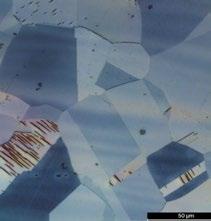
Figure 1a-f shows optical and scanning electron micrographs (SEM) of the as-received A357-T61 and C355-T61 alloy substrates. The microstructure of these alloys, which are characterized by a silicon content of less than 12.6 wt% (hypoeutectic alloys), consists of α -Al dendrites, the eutectic Si phase, and various secondary intermetallic phases (Fig. 1a,d) [19,20]. Intermetallic phases, found in interdendritic regions and along grain boundaries, contain iron (Fe), magnesium (Mg), copper (Cu), manganese (Mn) and silicon (Si). The fraction, size, morphology, and composition of these phases, which are formed during the solidification process, depend on the chemical composition of the alloy and the solidification rate (solidification conditions) [9,21]. Based on the
literature and phase morphology [9,21-23], the A357-T61 microstructure consists mainly of small spherical Si particles (dark grey particles), Mg2Si particles, together with intermetallic π-(Al8Mg3FeSi6) phase, and a small number of α-Al5FeSi phase (Fig 1b,c). In contrast, the C355-T61 substrate exhibits a coarser microstructure due to its higher levels of copper (Cu) and manganese (Mn). Specifically, it can be observed coarse polyhedric Si particles and the presence of other new intermetallic phases, such as the Q-Al5Cu2Mg8Si phase (Fig. 1e,f). A comparison of Figures 1b and 1ereveals clear differences in the size and shape of the silicon particles. It is known thattheshapechangeofSieutecticmorphologyoccursin two stages: dissolution or fragmentation and granulation or spheroidization. Several researchers have argued that treating alloys with Sr before solution heat treatment facilitates the fragmentation of acicular silicon [24-26]. These different microstructural affect the mechanical properties, with a reduction in hardness. However, this reduction is offset by the greater dimensional stability of the precipitates, making the alloy less susceptible to shrinkage phenomena resulting from exposure to high operatingtemperatures.Inparticular,itwasfoundthatthe microhardness of the substrate and the A357-T61 alloy electrode was 110 ± 3 HV and 58.2 ± 2 HV, respectively. While the microhardness of the substrate and C355-T61 alloyelectrodewas100±2HVand62.3±2HV.
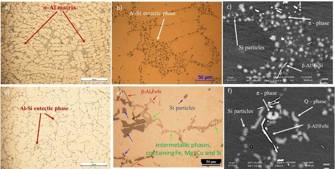
Fig.1-OpticalandSEMmicrographsoftheA357-T61andC355-T61substrates(basematerial),without chemicaletching. a)OMofA357-T61alloyshowingdendritesof α-aluminium,bandc)OMandSEM micrographsofA357-T61alloyshowingthespheroidizedeutecticSiparticlesandtheintermetallic phasescontainingFe,Mg,CuandSi,respectively.While,d)OMofC355-T61alloy,eandf)OMandSEM micrographsofC355-T61alloy,showinganinterdendriticnetworkofmostlyacicularAl-Sieutectic phaseandsecondaryintermetallicphases.
ESD is characterized by the ability to rapidly melt small amounts of electrode material using short pulses [14,15]. However, the amount of material involved in a layer deposition can vary significantly depending on the power discharge. Figure 2 a,b shows the cross-sectional macrograph (typical appearance) of coatings produced by the ESD process after 50 passes in aluminium alloy A357 using 33W (Fig. 2a) and in C355 using 37W (Fig. 2b). Interestingly, both deposits on A357 and C355 alloys exhibit similar widths, averaging around 1.6±1 mm. However, their thicknesses differ significantly depending on the discharge power used. Figure 3 shows a clear relationship between discharge power (P) and deposit thickness for both alloys. As the discharge power increases, the coating thickness also increases. Specifically, the C355 deposit thickness ranges
from 12.2 µ m (lowest power) to 169.2 µ m (highest power). The A357 alloy deposits are even thicker, varying between 180.4 and 463 microns. This is due to the greater amount of material transferred at higher powers [15,27], leading to a faster growth rate (GR). Interestingly, A357 coatings exhibit a significantly greater increase in growth rate compared to C355 coatings, even at similar discharge powers. This is attributed to the higher hardness of the C355 electrode material, which limits the amount of material transferred during the process. These findings are consistent with previous research, including studies on NiCrAlY coatings by Cao et al. [28] and WE43 coatings by Renna G. et al. [29], which also highlight the influence of deposition parameters and pulse-spark energy (Es) on deposit thickness.
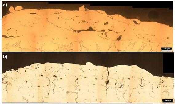
- OM of multiple-layer deposit products by ESD using a discharge power of: a) 33W for A357 alloy and b) 37W for C355 alloy; as can be seen, the deposits are affected by some defects.
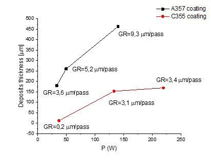
- Discharge power (P) vs. thickness for ESD deposits in A357 and C355 alloy.
Moreover, it was observed that the deposited coatings are affected by internal defects (see fig. 2 and fig. 4). These defects consist mainly of several voids, of different shapes-both spherical and laminar defects. These latter were likely caused by thermal stresses arising from the high-temperature gradients during the deposition process.Interestingly,theselaminarshapedefectscanbe found in two ways: perpendicular to the substrate/coating interface and parallel to it (fig. 4). Spherical voids, typically ≤10 µm in size, are likely caused by
entrapped gas during the deposition process. In addition, during the coating process, the molten material may not be evenly distributed, leading to the formation of voids between adjacent deposited splats. These defects characterized by acicular-shaped voids are called bridging defects (fig. 4). The presence of these acicular voids (bridging defects) is detrimental to the strength of the coatings. Theyact as crack initiation sites, making the coatingsmoresusceptibletofailureunderstress[14,15].
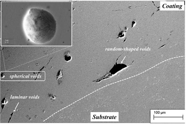
Figure 5 shows the microstructure of A357 and C357 coatings deposited using ESD, viewed perpendicularly to the direction in which the layers were deposited (build direction). Figure 5a specifically provides a general overview of the initial appearance of the coatings, while Figure 5b illustrates typical microstructural features in the central region of the coatings. Regardless of the alloy used or electrical parameters set, the microstructures of the A357 and C355 coatings exhibit a distinct characteristic: thin, overlapping layers, forming a “layer-on-layer” structure (fig. 5b). This is attributed to the nature of the ESD process, where molten material is deposited layer by layer. Furthermore, the rapid cooling rates (105-106 °C/s) inherent to ESD lead to the formation of fine-grained microstructures within the coatings [15]. Interestingly, a closer examination using scanning electron microscopy reveals a cellular morphology within each layer (fig. 5
c,e). Additionally, at the interface between two adjacent layers, an equiaxial microstructure is observed (fig. 5 d,f). Rapid solidification theory helps explain the differences in the solidification structures observed. Kurz and Fisher [30] demonstrated that the ratio between the temperature gradient (G) and the solidification rate (V) is the key factor determining the final microstructure morphology. In other words, the relationship between the temperature gradient and the solidification rate affects the formation of microscopic structures during the solidification process. For example, a low solidification velocity and a hightemperature gradient may favor the formation of finegrained structures, while opposite conditions may lead to the formation of coarser-grained structures [15].
Figure 6 a,b demonstrates the good adhesion between the ESD coatings and the substrates for both investigated alloys. Furthermore, there is no significant thermal impact on the substrates observed during the ESD process
(absence of heat-affected zone). Instead, Figures 6c and 6d show the presence of small Si eutectic particles partially or fully embedded within the coating, surrounded by a cellular structure. These particles likely originate from the substrate material, due to the intermixing of the BM and electrode materials during the ESD process. This mixing is believed to occur because the heat input involved in ESD is high enough to melt not only the electrode material but also a thin film of the substrate material.
It is noteworthy that, unlike A357 alloy coatings, the C355 alloy coatings interface was characterized by the presence of perpendicularly propagating cracks in the substrate (Figure 7a,b). This type of defect was also found in other ESD-treated aluminium alloys, such as alloy 2024. Both the morphology (shape and size) of the silicon particles and the morphology and distribution (arrangement) of the secondary phases (Fe-containing intermetallics) are believed to significantly influence the formation of cracks at the interface. Therefore, the amount of eutectic structure can influence the coating quality. In general, during the
deposition process, the coarse eutectic structure of silicon can negatively impact the deposition process. These large silicon particles can hinder the material’s ability to expand uniformly (volumetric expansion) during solidification, leading to localized areas of stress and crack formation [22].
In contrast, substrates with finer eutectic structures, like A357, allow an engulfment mechanism of silicon particles within the first deposited layers, resulting in a stronger and more uniform bond between the coating and the substrate. Furthermore, the presence of acicular (needleshaped) intermetallic phases, such as β -phase, within the substrate adds another aspect of complexity. These intermetallics, due to their brittle nature, can act as stress concentrators, making them susceptible to fracture even before eutectic silicon. In addition, their morphology acts as stress concentration points, further contributing to the formation of microfractures that propagate at the interface between the intermetallics and the surrounding matrix.
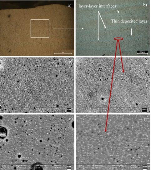
Fig.5-Microstructuralanalysisofthecoatings:a)OMrepresentingthetypicalaspectofcross-section coatings,b)OMofthecentralregionofthecoatingcross-sectionafterchemicaletchingshowingthetypical layer-by-layermicrostructure,c)SEMmicrographshowingthecelltypemorphologywithineachlayerfor thecoatinginA357alloy,d)SEMmicrographshowingtheequiaxedtypemorphologywithineachlayerlayerinterfaceforthecoatinginA357alloyande)SEMmicrographshowingthecelltypemorphologywithin eachlayerforthecoatinginC355alloy,f)SEMmicrographshowingtheequiaxedtypemorphologywithin eachlayer-layerinterfaceforthecoatinginC355alloy.
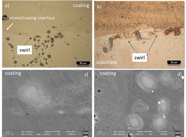
Fig.6 - Microstructural analysis of the substrate/coating interface: a) OM of the interface region for A357 coating, b) OM of the region for the C355 coating and c, d) SEM micrographs of the interface region for the coating in A357 and C355 alloy, respectively.
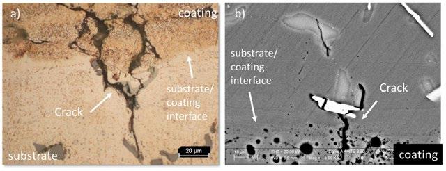
Fig.7 - Coatings in C355 alloy: a) OM and b) SEM micrograph of the coating/substrate interface showing the crack that propagates in the substrate along intermetallic phases.
DEFECT ANALYSIS AND COATING HARDNESS.
Table 3 presents the average crack length and occurrence frequency for the C355 samples processed at the three different discharge powers. The occurrence frequency is calculated as the ratio of the number of observed cracks to the total length of the examined interface. Interestingly, the occurrence frequency at the interface remains consistent regardless of the applied power in the ESD process. However, the average crack length increases with increasing power. This phenomenon can be explained by considering two key factors: the location of crack initiation remains consistent across all three depositions due to the inherent characteristic microstructural of the substrate (distribution and morphology of the secondary
phases). Secondly, as the applied power increases, the heat input to the substrate also increases. This additional heat contributes to the growth of the triggered cracks, leading to an increase in their average length [14].
To evaluate the coatings’ resistance and durability and to indicate the amount of defects present in the coatings, microhardness and percentage defects measurements were performed. The percentage area fraction of defects was calculated as the ratio of the area of the voids present to the area of the examined coating.
Figure 8 illustrates the average microhardness and percentage area fraction of defects across the crosssection of A357 and C355 samples, as a function of the applied power. Both A357 and C355 coatings exhibit a
limited overall defect percentage, with A357 below 4% and C355 below 7% of the total surface area. Notably, in A357 and C355 coatings, the percentage of defect area shows a decreasing trend with increasing power. The decrease is much more pronounced for the C355 alloy. The authors attribute the observed decrease in defects with increasing power to a reduction in laminar defects. These defects are typically associated with the ESD process due to its high energy density and low heat input, leading to both parallel ("delamination cracks") and perpendicular cracks at the interface [20,31]. Delamination cracks are primarily linked to poor mixing between the electrode material and previously deposited layers, while perpendicular cracks are generally attributed to high thermal gradients [20,31].
Higher power settings lead to the melting of larger volumes of electrode and substrate material, promoting better mixing and adhesion between them. This potentially reduces delamination cracks. Additionally, the increased power raises the temperature of the substrate and existing layers, minimizing thermal gradients and further reducing the risk of crack initiation.
Despite the expectation of higher microhardness due to their finer microstructure, the coatings exhibit lower hardness compared to the substrate. This is likely due to the widespread presence of defects. Supporting this, the lowest hardness for C355 coincides with the highest defectivity observed at the minimum power setting (at minimum power).
Tab.4 - Average crack length and the ratio between the cracks number and interface length examined (occurrence frequency) for the coatings in C355 alloy.
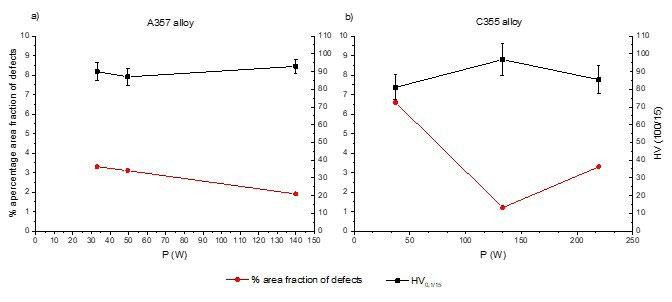
- Microhardness and percentage area fraction of defects as a function of discharge power (P) for a) A357 alloy and b) C355 alloy.
The study and comparison of coatings in A357 and C355 prepared on the as-cast substrates in homologous material by ESD produced the following results:
• The microstructural analysis shows that a nanostructured solidification structure for A357 and C355 coatings can be commonly achieved by this technique. However, the powers used to deposit both alloys do not result in changes in the microstructure. All coatings share a common microstructure: overlapping layers with distinct interfaces.
• The morphology (shape and size) and distribution of silicon (Si) particles and secondary phases within the substrate significantly influence the formation of the coatings. This is because these features can affect the formation of defects at the interface between the substrate and the coating.
• Both coatings exhibited defects of various shapes,
including laminar, spherical, and random. Unlike the A357 coatings, C355 coatings exhibit a new type of defect: cracks propagating perpendicularly (at right angles) into the substrate from the coating interface.
• The number of cracks at the interface remains constant regardless of the applied power during the ESD process. However, the average crack length increases with increasing power. This suggests that the crack initiation points, likely determined by the substrate's microstructure, remain consistent across the three depositions.
• Despite variations in discharge power, the microhardness of A357 and C355 coatings remains lower than the substrate, primarily influenced by the presence of internal defects.
• Generally, higher applied power, and current density, promote the growth of coating.
[1] W.S. Miller, L. Zhuang, J. Bottema, A.J. Wittebrood, P. De Smet, A. Haszler, A. Vieregge, Recent development in aluminium alloys for the automotive industry, Mater. Sci. Eng. A 80 (2000) 37–49.
[2] ASM Handbook, 18, Friction, Lubrication, and Wear Technology, S.D. Henry (Ed.), ASM International (1992) 553–562, 786–794
[3] M. Elmadagli, T. Perry, A.T. Alpas, A parametric study of the relationship between microstructure and wear resistance of Al–Si alloys, Wear 262 (2007) 79–92
[4] Khaled Salem Alhawari, Mohd Zaidi Omar, Saziana Samat, Ahmad Muhammad Aziz. Effect of magnesium addition consolidated by the thixoforming process on the wear properties of A319 alloy, The International Journal of Advanced Manufacturing Technology https://doi.org/10.1007/s00170-024-13288-2
[5] N.D. Alexopoulos, Sp.G. Pantelakis, Quality evaluation of A357 cast aluminum alloy specimens subjected to different artificial aging treatment. Materials and Design 25 (2004) 419–430
[6] I.J. Polmear, Light Alloys: Metallurgy of the Light Metals, Butterworth Heinemann, 1995
[7] Davis, J.R. ASM specialty handbook: Aluminum and Aluminum Alloy. ASM International; 1993.
[8] Engler-pinto Jr, C.C., et al., A comparative investigation on the high temperature fatigue of three cast aluminum alloys. SAE Transactions, 2004. Paper # 2004-01-1029.
[9] G. Mrówka-Nowotnik, J. Sieniawski Microstructure and mechanical properties of C355.0 cast aluminium alloy, Archives of the material science and engeniring Volume 47, Issue 2, February 2011, Pages 85-94
[10] Z. Li, A.M. Samuel, F.H. Samuel, C. Ravindran, S. Valtierra, H.W. Doty, Parameters controlling the performance of AA319-type alloys Part I. Tensile properties, Materials Science and Engineering 367 (2004) 96-110.
[11] Z. Li, A.M. Samuel, C. Rayindran, S. Valtierra, H.W. Doty, Parameters controlling the performance of AA319-type alloys: Part II. Impact properties and fractography, Materials Science and Engineering 367 (2004) 111-122.
[12] F. King, Aluminium and its alloys, John Willey and Sons, New York, Chichester, Brisbane, Toronto, 1987.
[13] Victor Verbitchi, Cristian Ciuca, Radu Cojocaru, Electro-Spark Coating with Special Materials. Nonconventional Technologies Review – no. 1/201
[14] Paola Leo, Gilda Renna and Giuseppe Casalino, Study of the Direct Metal Deposition of AA2024 by ElectroSpark for Coating and Reparation Scopes Appl. Sci. 2017, 7, 945
[15] Barile, C.; Casavola, C.; Pappalettera, G.; Renna, G. Advancements in Electrospark Deposition (ESD) Technique: A Short Review. Coatings 2022, 12, 1536. https://doi.org/10.3390/coatings12101536ù
[16] Wang, P.Z.; Pan, G.S.; Zhou, Y.; Qu, J.X.; Shao, H.S. Accelerated Electrospark Deposition and the Wear Behavior of Coatings. J. Mater. Eng. Perform. 1997, 6, 780–784.
[17] Xie, Y.J.; Wang, M.C. Microstructural morphology of electrospark deposition layer of a high gamma prime superalloy. Surf. Coat. Technol. 2006, 201, 691–698
[18] Liu, D.Y.; Gao, W.; Li, Z.W.; Zhang, H.F.; Hu, Z.Q. Electro-spark Deposition of Fe-based Amorphous Alloy Coatings. Mater. Lett. 2007, 61, 165–167.
[19] P. Cavaliere, E. Cerri, P. Leo, Journal of Materials Science, volume 39, issue 5, year 2004, pp. 1653 – 1658
[20] P. Leo, G. Renna, Rivestimenti via Electrospark Deposition in lega A357: microstruttura e difettosità. La Metallurgia Italiana - n. 9 2019
[21] Lorella Ceschini, Alessandro Morri, Andrea Morri, Stefania Toschi, Sten Johansson, Salem Seifeddin Effect of microstructure and overaging on the tensile behavior at room and elevated temperature of C355-T6 cast aluminum alloy. Materials & Design 83 (2015) 626–634
[22] Davis, J.R. ASM specialty handbook: Aluminum and Aluminum Alloy. ASM International; 1993
[23] L.F. Mondolfo, Aluminium Alloys: Structure and Properties, London-Boston, Butterworths, 1976.
[24] B. Parker, “Quantitative evaluation of the microstructure of a strontium-modified Al-Si-Mg alloy following prolonged solution treatment,” Metals Forum, vol. 5, no. 1, pp. 48–53, 1982.
[25] F. N. Rhines and M. Aballe, “Growth of silicon particles in an aluminum matrix,” Metallurgical Transactions A, vol. 17, no. 12, pp. 2139–2152, 1986.
[26] Mohamed Ibrahim, Mohamed Abdelaziz, Agnes Samuel, Herbert Doty, and Fawzy Samuel Spheroidization and Coarsening of Eutectic Si Particles in Al-Si-Based Alloys Advances in Materials Science and Engineering Volume 2021, Article ID 6678280, 16 pages https://doi.org/10.1155/2021/6678280
[27] Heard, D.W.; Brochu, M. Development of a nanostructure microstructure in the Al–Ni system using the electrospark deposition process. J. Mater. Process. Technol. 2010, 210, 892–898
[28] Cao, G.J.; Wang, Y.Y.; Tang, G.Z. Properties of NiCrAlY coatings fabricated on superalloy GH4169 by electrospark deposition. Int. J. Adv. Manuf. Technol. 2018, 96, 1787–1793.
[29] Gilda, R.; Paola, L.; Caterina, C. Effect of ElectroSpark Process Parameters on the WE43 Magnesium Alloy Deposition Quality. Appl. Sci. 2019, 9, 4383.
[30] W. Kurz D. J. Fisher, Fundamentals of Solidification, Trans Tech Publications, Switzerland 1998
[31] M.H. Staia, A. Fragiel, M. Cruz, E. Carrasquero, B. Campillo, R. Perez, M. Constantino , T.S. Sudarshan, Wear 251 (2001) 1051– 1060
Cr2N films with different silver additions (3-15 wt.%) were deposited on Vanadis 6 steel substrates using reactive magnetron sputtering, at a temperature of 500 °C. The obtained nanocomposite films are composed of the Cr2N matrix with embedded metallic Ag particles. These particles are located on the crystal boundaries and their size is mostly up to 35 nm. The films grow in a typical columnar manner and have a thickness from the range 3.7 - 5.1 µ m. The Ag addition (up to 11 wt.%) slightly increases the film hardness, its Young´s modulus and adhesion to the substrate. The friction coefficient decreases rapidly with increasing the testing temperature. This is also reflected in generally lowered wear rate, as compared with Ag-free Cr2N film. The 15 wt.% Ag addition, on the contrary, induces decrease in mechanical properties of the films, their lower adhesion on the substrate, and weaker tribological performance. Lower friction coefficient at elevated temperatures is attributed to silver migration to the free surface providing the films self-lubrication. An optimal temperature where the self-lubricating affect is most active is around 400 °C. A common practical recommendation can be derived based on the obtained results. If the goal is to get the best mechanical properties (nanohardness, Young´s modulus) then the addition of 11 wt. % Ag into the Cr2N is recommended. Alternatively, the Cr2N-7Ag films can be designed for specific operation conditions where excellent tribological properties are required.
KEYWORDS: AG-CONTAINING FILMS, MICROSTRUCTURE, NANOHARDNESS, ADHESION, TRIBOLOGICAL PERFORMANCE
Magnetron-sputtered nanocomposite ceramic films with silver additions have attracted a great attention due to their wide range of applications. The addition of Ag expands the already existing properties of the films, providing them multiple “extra” characteristics such as antibacterial effects [1] wear resistance [2, 3, 4], self-lubrication properties at elevated temperatures, corrosion resistance [5] and light absorption enhancement [6].
Silver does not form carbides or nitrides and is in the metallic state in film. The mechanical properties of these films are mainly determined by their microstructure. Since the silver is insoluble in ceramics, only the microstructural changes due to Ag incorporation are responsible for modifying the mechanical properties. In general, an increase in silver produces a reduction of the hardness and Young’s modulus of the films [7, 8]. But an opposite tendency was recorded for low silver contents since the Ag addition induces the grain refinement of the films [4, 8]. This refinement lowers the dislocation motion rate and may also prevent crack development inside the films.
Slovakia
Conversely, more Ag segregates at the crystal boundaries at higher Ag contents incorporated into the matrix, thus enhancing the ductility, reducing the internal stresses and consequent hardness decrease.
In industrial applications, the combination of a hard ceramic film´s matrix and silver as a solid lubricant is one of the main purposes of depositing Ag-containing films. The self-lubricating properties of these films are apparent mainly at elevated temperatures, due to the migration of Ag to the surface [7, 8, 9, 10, 11]. The silver amount and its distribution on the surfaces are dependent on the silver content in the films. More extensive silver migration is usually achieved by increasing the Ag-content [12].
The driving force of the mobility of silver atoms is a result of synergy of several sources: (i) chemical potential of Agparticles [10, 11], (ii) concentration differences between the film’s bulk and its surface, (iii) stress state of the film, and (iv) thermal energy (this is of why the silver transport is more active at elevated temperatures). Since the most common morphology of CrxNy is columnar, the Ag-atoms diffuse along the column boundaries that act as diffusion channels [3, 6].
In most cases, the CrxNy films are used in dry conditions. Under these conditions, the silver diffusion/migration to the surface is the key parameter controlling the self-lubricating features of film. Silver has very low shear strength. When forming islands at the surface it is capable to act as a lubricant during sliding against various counterbodies, especially at elevated temperatures [4, 13]. The result is, among others, the reduction of the friction coefficient (FC). Even at room temperature testing, reduction of the FC has been reported for larger Ag contents compared to the FC of pure CrxNy [3, 4].
The opinions on the effect of Ag addition on the wear rate are inconsistent to date. In some works, a reduction of the wear rate of Cr x Ny-Ag films (as compared with pure CrxNy) was reported [3, 13] while increased wear rate [2, 4] was determined in others. Of note, the functionality of silver as a solid lubricant depends on certain conditions. First, silver must migrate to the free surface of the films. Second, the wear rate depends on the Ag depletion time because, after silver reservoir in the films is exhausted, a more unstable porous structure underneath the surface is created, causing film´s failure [2]. Therefore, an equilibrium among the Ag content, silver mobility and the stability of the matrix must be reached to be able to exploit these self-assembled silver nanoparticles in a self-lubricating system.
The substrate material was the Vanadis 6 steel (heat-treated to 60 ± 0.5 HRC) with mass fractions 2.1 % C, 1.0 % Si, 0.4 % Mn, 6.8 % Cr, 1.5 % Mo, 5.4 % V and Fe as the balance. The films were deposited by magnetron sputtering, in a pulse regime with a frequency of 40 kHz. Just prior to the deposition, the substrates were sputter cleaned in an argon low-pressure atmosphere for 15 min. A negative substrate bias of 200 V was used for the sputter cleaning and that of 100 V for the deposition. The total deposition time was 6 h. In the case of the Cr2N film, during the deposition, the power was 2.9 kW per cathode (both Cr). To produce the Ag-containing films, the power of the Cr cathode was kept at 5.8 kW, while the power of the Ag cathode was varied (0.10, 0.21, 0.34 and 0.45) kW in order to prepare the films with different Ag concentrations (3, 7, 11 and 15) wt.%. The processes were carried out in a low pressure atmosphere (0.15 mbar), containing nitrogen and argon in a ratio of 1:4.5, at a deposition temperature of 500 °C.
Typical microstructures were obtained by investigations using a scanning electron microscope (SEM) coupled with energy-dispersive spectroscopy (EDS). The phase constitution of nanocomposite films was determined by X-ray diffraction. The nanohardness and the Young´s modulus (E) values were measured using the instrumented nanoindentation test under a normal load of 60 mN using a Berkovich indenter. The penetration depth (and the loading) was chosen to not exceed one tenth of the film thickness, to minimize the substrate effect. The adhesion has been examined using a CSM Revetest scratch-tester. The scratches were made under a progressively increasing load from 1 N to 100 N, with a loading rate of 50 N/min. Standard Rockwell diamond indenter with a tip radius of 200 μ m was used. Five measurements have been made and the mean value and standard deviation of adhesion properties, represented by the critical load when the first side delamination of the film occurred. Tribological properties were measured using the CSM Pin-on-disc tribometer at ambient and elevated temperatures, up to 500 oC. Balls 6 mm in diameter, made of sintered alumina were used for tests. No external lubricant was added during the measurements. The normal loading F used for the investigations was 1 N. For each measurement, the total sliding distance L was 100 m. The volume loss of coated samples was calculated by using the ASTM G99-17 procedure [14].
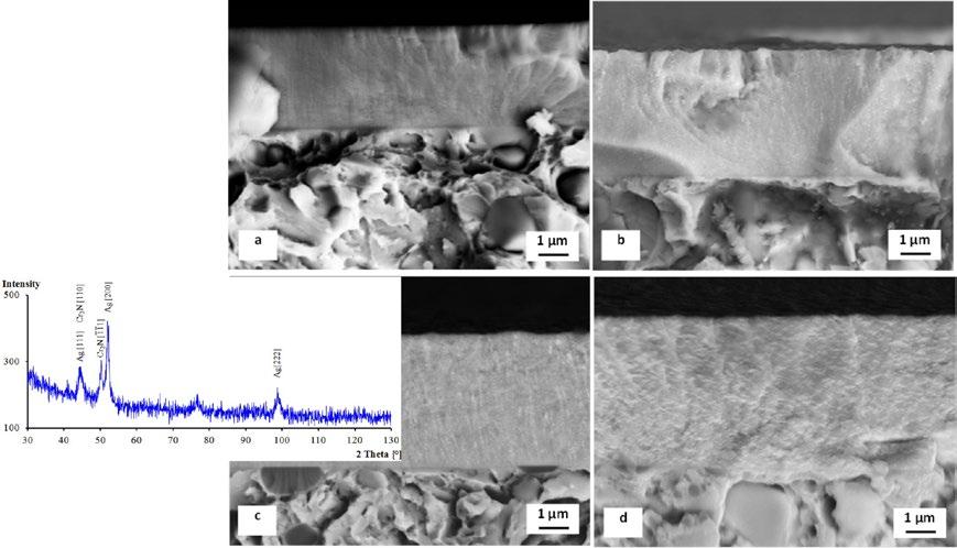
SEM images in Fig. 1 show cross-sectional microstructures of the obtained films. At 3 wt.% Ag addition the silver particles are almost invisible on the image, Fig. 1a. The total film thickness is 3.7 μ m. In contrast, individual silver particles are well visible at 7 and 11 wt. % Ag addition, due to much higher backscattered electron yield of silver as compared with the film´s matrix, Figs. 1b, c. The total
thickness of these two films is 4.3 μ m. However, the silver particles in 15 wt.% Ag film appear in completely different way. As seen in Fig. 1d, silver forms lamellae that are oriented longitudinally to the surface, and have few hundreds of nm in length and less than 50 nm in width. Also it is seen that higher Ag addition fosters the film growth rate. The thickness of 15 wt.% Ag film is 5.1 μ m.
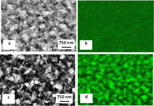
The Ag-particles are located mainly at the crystal boundaries, Fig. 2a,c. Their size is far below 50 nm in the case of 7 wt.%Ag film, but it may increase to several hundred nm for 15 wt.% Ag film. In this case the Ag is well visible on corresponding EDS map, Fig. 2d.
The nanohardness of Ag-free Cr2N film is 16.8 ± 1.5 GPa, Fig. 3a. As seen in the diagram, the Ag additions up to 11 wt.% affect the nanohardness only slightly while 15 wt.% Ag reduces this property to 11.4 ± 0.6 GPa. The Young modulus (E) of pure Cr2N is 244 ± 15 GPa, Fig. 3b. The Ag-addition leads to “almost no effect” on the E (at 3 or 7 wt.%), slight increase (11 wt.%) or rapid decrease (15
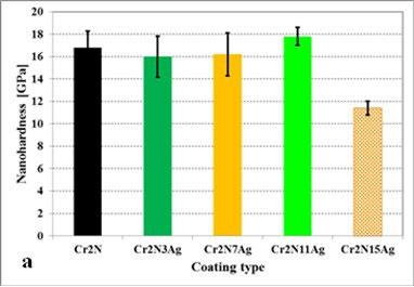
wt.%). The nanohardness measurements results are in good agreement with the literature [15]. It is stated that an increase in silver produces generally a reduction of the hardness and Young’s modulus of the films. However, it was also found that the hardness can increase at low Ag contents, due to the grain refinement of the films. According to the data from [15] the maximum silver content leading to hardness increase is up to 15 at.%. On the other hand, the data on the effect of Ag on the E are inconsistent to date. One can only hypothesise based on the results reported in [16], that when the silver is added, the film is densified, and thereby makes it stiffer.
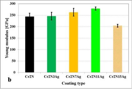
- Mechanical properties of Cr2N-Ag films with different Ag contents. Cr2N without a silver addition is a reference: a) nanohardness, b) Young´s modulus.
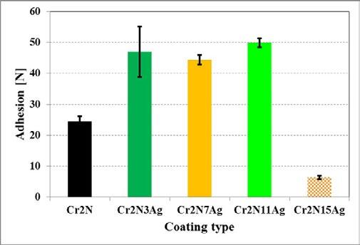
The adhesion of films is improved by adding low silver amounts, Fig. 4. This may be due to the reduction of internal stresses within the films, owing to plastic deformation of silver particles. But, this effect is suppressed at higher
silver additions. The film becomes softer and thereby less resistant to the application of normal load during the scratch test. At this place it should be noted that, for instance, Yao et al. [17] arrived in very similar findings.
The effect of silver addition on the friction coefficient is minimal at 20 °C, Fig. 5. However, significant reduction of FC was recorded at higher temperatures. When tested at
300 °C, the lowest FC had the film with 15 %Ag addition, but the situation was changed in favour of 7 wt.%Ag containing films in the case of testing at 400 or 500°C.
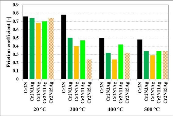
Fig.5 - Average (steady state) friction coefficient of Cr2N-Ag films with different Ag contents, measured at different testing temperatures. Cr2N without a silver addition is a reference.
The silver addition affects the wear rate only slightly during testing at 20 °C, except the 15 wt.% Ag film, Fig. 6. 15 wt.% Ag addition gives higher wear rate because of significant softening of the film. No effect of 3 wt.% Ag addition on the wear rate has been recorded at testing temperature of 300 °C, probably due to insufficient Ag content enabling the migration of Ag atoms to the free surface [12]. Increased
wear rate of 15 wt.% Ag containing film (not only at 300, but also at 400 and 500 °C), in the other hand, is a result of extensive softening of the film due to very high silver content. The 7 and 11 wt.% Ag gave very promising results with respect to the wear rate, when tested at 300 – 500 °C. However, at either 400 or 500 °C, also the 3 wt.% Ag works well.
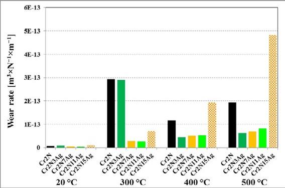
Fig.6 - Wear rate of Cr2N-Ag films with different Ag contents, measured at different testing temperatures. Cr2N without a silver addition is a reference.
Cr2N films with 3-15 wt.% Ag additions were synthetised on Vanadis 6 steel substrates using reactive magnetron sputtering. The microstructure, nanohardness, Young´s modulus, adhesion and tribological characteristics were investigated. The main outcomes of the experiments are the following:
The microstructures of films consisted of Cr2N matrix with embedded Ag particles, mainly on the crystal boundaries. The Ag additions up to 11 wt.% have slightly positive effect on the nanohardness, Young´s modulus and adhesion of the films to the substrate.
The Ag-containing film manifest self-lubricating behaviour at elevated temperatures, which was demonstrated by
more than one half reduced friction coefficient. The wear rate is considerably reduced for 7-11% containing filmss at al testing temperatures.
The 15%Ag addition reduced the mechanical properties of the films, which resulted in worsening of the wear performance despite superior reduction of friction coefficient.
Therefore, an addition of 7-11 %Ag additions can be recommended to obtain the best mechanical properties along with tribological performance of the films.
The author acknowledges that the work is a result of implementation of the project VEGA 1/0345/22.
[1] Skovager A, Whitehead K, Wickens D, Verran J, Ingmer H, Arneborg N. A comparative study of fine polished stainless steel, TiN and TiN/Ag surfaces: adhesion and attachment strength of Listeria monocytogenes as well as anti-listerial effect. Colloids Surf B 2013;109:190–196.
[2] Mulligan CP, Blanchet TA, Gall D. CrN–Ag nanocomposite coatings: high-temperature tribological response. Wear 2010;269:125–131.
[3] Mulligan CP, Gall D. CrN–Ag self-lubricating hard coatings. Surf Coat Technol 2005;200:1495–1500.
[4] Basnyat P, Luster B, Kertzman Z, Stadler S, Kohli P, Aouadi S, Xu J, Mishra SR, Eryilmaz OL, Erdemir A. Mechanical and tribological properties of CrAlN-Ag self-lubricating films. Surf Coat Technol 2007;202:1011–1016.
[5] Zhou F, Qian J, Zhang M, Wu Y, Wang Q, Zhou Z. Tribocorrosion properties of CrMoN/Ag coatings with various Ag contents in seawater. Surf Coat Technol. 2023;473:129993.
[6] Siozios A, Zoubos H, Pliatsikas N, Koutsogeorgis DC, Vourlias G, Pavlidou E, Cranton W, Patsalas P. Growth and annealing strategies to control the microstructure of AlN: Ag nanocomposite films for plasmonic applications. Surf Coat Technol 2014;255:28–36.
[7] Hong Ch, Huan Y, Zhang P, Zhang K, Dai P. Effect of silver content on the microstructure, thermal stability and mechanical properties of CrNx/Ag nanocomposite films. Ceram Int 2021;47:25324–25336.
[8] Rajput SS, Gangopadhyay S, Yaqub TB, Cavaleiro A, Fernandes F. Room and high temperature tribological performance of CrAlN(Ag) coatings: The influence of Ag additions. Surf Coat Technol. 2022;450:129011.
[9] Cavaleiro D, Munnik F, Krause M, Carbo-Argibay E, Ferreira PJ, Cavaleiro A, Fernandes F. The role of interfaces and morphology on silver diffusion in hard coatings. Surf Interfaces 2023;41:103182.
[10] Mulligan CP, Papi PA, Gall D. Ag transport in CrN–Ag nanocomposite coatings. Thin Solid Films 2012;520:6774–6779.
[11] Jurči P, Bílek P, Podgornik B. Cr2N0.62-11Ag adaptive nanocomposite thin films: Transport of Ag solid lubricant during annealing in a closed-air atmosphere. Thin Solid Films 2017;639:127–136.
[12] Xiong J, Ghori MZ, Henkel B, Strunskus T, Schürmann U, Kienle L, Faupel F. Controlling surface segregation of reactively sputtered Ag/TiOx nanocomposites. Acta Mater 2014;74:1–8.
[13] Incerti L, Rota A, Valeri S, Miguel A, García JA, Rodríguez RJ, Osés J. Nanostructured self-lubricating CrN-Ag films deposited by PVD arc discharge and magnetron sputtering. Vacuum 2011;85:1108–1113.
[14] US-ASTM. ASTM G99-17 Standard test method for wear testing with a Pin-on-Disk apparatus. ASTM; 2017.
[15] Calderon Velasco S, Cavaleiro A, Carvalho S. Functional properties of ceramic-Ag nanocomposite coatings produced by magnetron sputtering. Prog Mater Sci 2016;84:158–191.
[16] Xu S, Gao X, Hu M, Sun J, Wang D, Zhou F, Weng L, Liu W. Morphology evolution of Ag alloyed WS2 films and the significantly enhanced mechanical and tribological properties. Surf Coat Technol 2014;238:197–206.
[17] Yao SH, Su YL, Kao, WH. Effect of Ag/W addition on the wear performance of CrN coatings prepared by RF unbalanced magnetron sputtering. Mater Sci Eng 2005;A398:88–92
A. Palombi, R. Montanari, A. Varone, C. Verona, E. Bolli, S. Kaciulis, A. Mezzi, A. Lanzutti, F. Sordetti, E. Vaglio
To improve surface hardness and wear resistance of austenitic stainless steels, conventional treatments, carried out at temperatures above 550°C, are not suitable. Therefore, low-temperature treatments have been developed; among them, one of the most promising is plasma-assisted carburizing. In fact, this treatment leads to relevant improvements in surface hardness in very short time frames (less than 8 hours). Previous studies have proved that low-temperature plasma-assisted carburizing treatments can be successfully employed to improve surface hardness of stainless steels produced with both conventional manufacturing processes and additive manufacturing (AM). Since additive manufacturing leads to higher mechanical properties, further analyses have been carried out on 316 L stainless steel produced by Laser Powder Bed Fusion (L-PBF) in order to define optimal carburizing parameters. First, gas carburizing mixtures with different amounts of CH4 and H2 have been tested. After treatments of 7 hours at 475°C, the result is the formation of an expanded austenite layer (~25 μ m), responsible for the improvement of surface hardness, covered by a thin (~2 μ m) over-layer of diamond-like carbon (DLC), which mainly impacts the friction coefficient and lowers the wear resistance. The atmosphere composition of 2.5% CH 4+97.5%H2 led to the best results considering surface hardness and wear tests. Therefore, in order to determine the influence of treatment time on surface hardness improvement and DLC over-layer formation, new treatments, carried out in an atmosphere of 2.5% CH4+97.5%H2, at 475 °C and for shorter times, were performed. The preliminary results of this work indicate that 1 hour of treatment might be a good trade-off, since it leads to hardness values comparable to those obtained with longer treatments, but prevents the formation of the DLC over-layer.
Austenitic stainless steels are employed in various fields, from biomedical to energetic, due to their excellent corrosion resistance, weldability, and good mechanical properties. On the other hand, in many cases, thermochemical treatments, such as carburizing are required to improve their hardness and wear resistance. Typically, these treatments are performed at temperatures above 550 °C. In austenitic stainless steels, at those temperatures, precipitation of Cr carbides occurs with a consequent detrimental effect on the corrosion resistance. Therefore, low-temperature thermochemical treatments, such as Kolsterising, have been developed to obtain surface hardness improvements without negative effects on corrosion resistance (1), but they usually involve long treatment times.
Alessandra Palombi, Roberto Montanari, Alessandra Varone, Claudio Verona Department of Industrial Engineering, University of Rome “Tor Vergata”, Italy
alessandra.palombi@uniroma2.it, roberto.montanari@uniroma2.it, alessandra.varone@uniroma2.it, claudio.verona@uniroma2.it
Eleonora Bolli, Saulius Kaciulis, Alessio Mezzi
ISMN-CNR, Italy
eleonora.bolli@ismn.cnr.it, saulius.kaciulis@cnr.it, alessio.mezzi@cnr.it
A. Lanzutti, F. Sordetti, E. Vaglio
Polytechnic Department of Engineering and Architecture, University of Udine, Italy
alex.lanzutti@uniud.it, francesco.sordetti@uniud.it, emanuele.vaglio@uniud.it
A plasma-assisted carburizing treatment, which reduces treatment times, has been developed on 316 L stainless steel produced through traditional manufacturing processes (2, 3).
Additive Manufacturing (AM) processes, such as Laser Powder Bed Fusion (L-PBF), have been gaining increasing attention in recent years for the production of components used in different fields, from biomedical (4) to aerospace (5, 6). Many studies have been carried out on stainless steels to optimize the printing process (7, 8) and achieve better mechanical properties thanks to the finer microstructure (9-11) compared to traditionally manufactured ones. However, the improvements obtained are still not enough in terms of wear behaviour; therefore, further treatment could be necessary and the investigation of plasma-assisted treatment on the 3D printed material showed promising results (12, 13).
The result of plasma-assisted treatments is the formation of an expanded austenite layer (S-phase) covered by a Diamond-Like Carbon (DLC) over-layer. The treatments have been carried out in gas mixtures containing different amounts of CH4 and H2 and, although all plasma
treatments improved hardness and wear resistance, the one performed in an atmosphere consisting of 2.5% (CH4) + 97.5% (H2) was the most effective (12, 13). However, the hard and brittle DLC over-layer formed on the surface partially reduced the benefits in wear resistance (13). Since the growth of the DLC over-layer seems to occur after the formation of the S-phase, new treatments, for shorter times (0.5, 1 and 2 hours), have been performed, in a 2.5% (CH4) + 97.5% (H2) mixture, to determine the minimum time interval that guarantees hardness improvements without the formation of the DLC overlayer. The samples were investigated by X-ray diffraction (XRD), Raman spectroscopy, and micro-hardness tests.
MATERIALS AND METHODS
Sample preparation
316L stainless steel (nominal chemical composition reported in Tab. 1) samples were produced using Laser Powder Bed Fusion (L-PBF) technique. The diameter of the spherical particles of the used powder ranged from d10 = 18.17 μ m to d90 = 45.44 μ m.
Tab.1 - Nominal chemical composition (wt.%) of the 316 L stainless steel powders used to produce the samples to be treated
The samples were taken form 3D printed blocks (30.5 x 20.5 x 7 mm3) built on a Concept Laser M2 Cusing machine with the following parameters: laser power P = 180 W, scanning speed vs = 600 mm/s, laser spot diameter d l = 120 μ m, hatch distance hd = 105 μ m, layer thickness tl = 25 μ m; each layer was printed in the pattern described in a previous work by the same authors (14). The printer was equipped with a single-mode CW ytterbium-doped fibre laser (emission wavelength is 1070 nm). The process was carried out in an inert atmosphere of Ar. The microstructure of the printed material consisted of austenite and a residual δ -ferrite (~5% maximum content).
The blocks were cut into 7 x 6 x 2 mm3 bricks using a diamond saw. A mirror-like surface was obtained by
mechanical polishing with grinding papers and, last, a suspension of 0.3 μ m alumina powder in water; before plasma treatment, each sample was immersed for 10 minutes in a sonication bath. Three samples were prepared for each treatment time.
The samples were treated with a 2.5% CH4 plus H2 gas mixture for different times: 0.5, 1 and 2 hours. Surface treatments were performed using a microwave plasmaenhanced chemical vapour deposition (CVD) reactor (15). Before each plasma treatment, the samples were bombarded with hydrogen, for 15 minutes, on the surface to be treated to remove the passive oxidation layer.
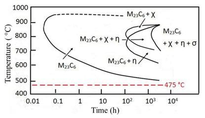
The chamber pressure and microwave power have been kept at a constant value of approximately 70 mbar and in the range 400 – 500 W, respectively, to obtain a temperature ~ 475 °C. This temperature has been proved
to be a good trade-off to reach good surface hardness improvements and to avoid precipitation of M23C6 carbides and undesirable phases ( η , χ and σ ) (1, 16).
Sample characterization
To investigate the results of the treatments, Vickers micro-hardness tests (micro-hardness tester Shimadzu Corporation, Kyoto, Japan) have been carried out on the samples using increasing loads (25, 50, 100, 200, 300, 500 and 1000 g) to determine the hardness vs. penetration depth profiles.
Since the improvement in micro-hardness strongly depends on carbon content, XRD measurement was
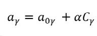
being α = 0.0044 nm / wt% C, a0 γ and a γ have been determined using the cos2 θ method (18).
To investigate the formation of the DLC over-layer, Raman Spectroscopy (RS, OPTOSKY, ATR 8300 Series, Xiamen, China) measurements were carried out in the spectral range of 200 - 2000 cm-1, at room temperature and in air by employing a laser wavelength of 785 nm.
Micro-hardness tests on the treated surface
For a homogeneous material, the values of microhardness do not depend on the load used in the test. In this case, due to the formation of a hardened C-rich
performed with a PW 1729 diffractometer (Philips, Eindhoven, The Netherlands) using the Mo-K α radiation, with a wavelength λ = 0.07093 nm, 2 θ steps of 0.005º and a counting time of 10 s per step, to record precision peak profiles. The values of C content C γ (wt%) in the S-phase of each treated sample were determined from the lattice parameters of the untreated austenite (a0 γ ) and S-phase (a γ ) through the empirical relationship proposed by Ridley et al. (17): (1)
S-phase layer, micro-hardness changes with increasing applied load: greater loads lead to deeper penetration of the indenting tip, and therefore the S-phase and substrate contribute differently to the results of the test. Moreover, the possible presence of a DLC over-layer can give rise to high Vickers micro-hardness values for low penetration depths.
The measured values are shown in Fig. 2, the Vickers micro-hardness values are plotted vs. penetration depth. The points in each curve correspond to the values measured in tests carried out by using loads of 25, 50, 100, 200, 300, 500 and 1000 g.
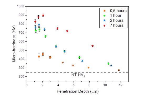
Fig.2 - Micro-hardness vs. penetration depth in samples treated for 0.5, 1 and 2 hours. The Vickers microhardness values of the untreated material (dashed line) and after 7 hours treatment (12) are reported for comparison.
From Fig. 2 it is evident that for all treatment times there is an improvement in surface hardness in comparison with the non-treated material (NT). Longer treatment times lead to higher micro-hardness values, but even after 0.5 hours of treatment, a significant improvement can be achieved.
For all samples, micro-hardness depends on the load used in the test with a significant decrease with increasing load. After 1 and 2 hours of treatment, the trend is similar to what was observed in samples treated for 7 hours, especially for the sample treated for 2 hours, the microhardness values for penetration depth lower than 2 μ m are comparable to what was obtained after 7 hours, but hardness values decrease more rapidly. These higher values at low penetration depth are in agreement with what has been observed in samples treated for longer times where a DLC over-layer of ~2 μ m thickness formed. The tests with higher loads show that the micro-hardness values of samples treated for 1 and 2 hours are comparable, meaning that there is no improvement in the properties of the S-phase. After 0.5 hours of treatment the hardness is significantly lower, but its value is always higher than that of the non-treated samples.
Increasing treatment times from 0.5 to 1 hour gives rise to improved hardness, between 1 hour and 2 hours, the main effect of a prolonged plasma exposure is the growth of an over-layer without any advantages in terms of S-phase
properties. Longer treatment times, for example for 7 hours, can increase surface hardness, but the formation of the DLC over-layer cannot be avoided.
XRD Analysis of the sample after plasma treatment From XRD analysis, it is possible to observe a shift toward lower angles of the peak positions of all treated samples compared to those of untreated steel (Fig. 3). This lattice expansion evidences the formation of the S-phase, responsible for the observed improvement in hardness. By determining the lattice parameter a γ of each sample, it is possible to calculate the C content using equation (1). For all three samples, the carbon content is around 2.0 wt.%, and the differences between them are within the experimental error (± 0.05 wt.%); this value, which represents the average on a thickness of approximately 50 μ m (18), is higher than that of the untreated material.
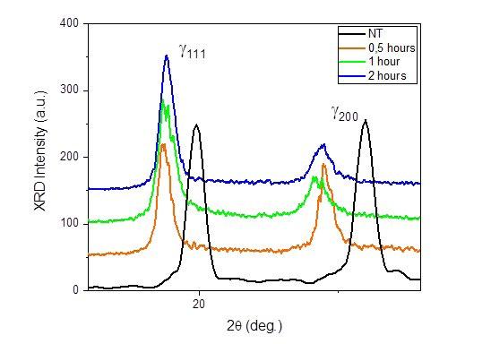
Fig.3 - {111} and {200} XRD reflection of 316 L steel produced by L-PBF in as-built condition (NT) and after plasma treatments carried out for 0,5, 1 and 2 hours.
Raman spectroscopy after plasma treatment
Raman spectra (Fig. 4) were collected to investigate the growth of the DLC over-layer on the S-phase. Since carbon can exist in electronic hybridisation states sp3 and sp2, the deposition of C atoms on a substrate can give rise to the formation of a great variety of crystalline and disordered structures: there are many different DLC phases of amorphous carbon. These phases are characterized by a specific ratio of sp 2/sp3 states (19), and their properties strictly depend on this ratio.
In Fig. 4 Raman spectra of non-treated steel and after 0.5, 1 and 2 hours of treatment are reported, as a comparison also the data of the sample after 7 hours of treatment are shown. It is possible to observe that no sample presents the typical diamond peak at 1332 cm-1 (20). As discussed
in a previous investigation, after a 7 hours treatment it is possible to observe two distinct peaks: the D and G peaks, related to sp2 hybridization states which correspond to neighbour atoms moving in opposite directions in the plane of the graphitic sheet (D peak) or perpendicular to this plane (G peak). The presence of those peaks indicates the formation of a DLC over-layer, which was confirmed by other observations. In the new samples, up to 1 hour of treatment no DLC over-layer formed on the surface since the D and G peaks intensities are comparable to the spectrum of non-treated material. After 2 hours of treatment, the peaks are more distinct and their intensity is significantly higher, meaning that a DLC over-layer is present on the treated surface.
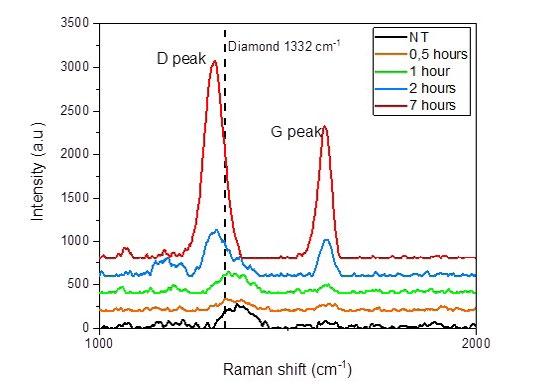
Fig.4 - Raman spectra of 316 L steel produced by L-PBF in as-built condition (NT) and after plasma treatments for 0,5, 1 and 2 hours. Raman spectra of the sample after 7 hours of treatment (12) are reported as a comparison.
Based on previous investigations, new low-temperature plasma-assisted treatments in 2.5% (CH4) + 97.5%(H2) atmosphere have been carried out for shorter treatment times to determine the minimum time interval to obtain the formation of the S-phase and to prevent the growth of a DLC over-layer.
• The S-phase forms even after short treatment times (0.5 hours), but its properties change after 1 hour of treatment.
• No significant improvements in the properties of S-phase can be observed between 1 hour and 2 hours; the only effect of a longer treatment is the formation of the undesired DLC over-layer.
• All the samples present higher values of surface hardness compared to the non-treated material, even if they are lower than the one obtained after 7 hours of treatment.
From these preliminary results, the best trade-off seems to be the treatment carried out for 1 hour since it leads to surface hardness values comparable to the ones obtained after longer treatments but prevents the formation of the DLC over-layer which hinders the wear behaviour. Therefore, longer treatments seem to be disadvantageous. To confirm these results, the wear behaviour of samples treated for 0.5, 1 and 2 hours will be investigated in further research.
[1] Collins, S.R., Williams, P.C. Low-temperature colossal supersaturation. Adv. Mater. Process 2006, 164, 32–33.
[2] Ciancaglioni, I., Donnini, R., Kaciulis, S., Mezzi, A., Montanari, R., Ucciardello, N., Verona-Rinati, G. Surface modification of austenitic steels by low temperature carburization. Surf. Interface Anal. 2012, 44, 1001–1004.
[3] Balijepalli, S.K., Ceschini, L., Ciancaglioni, I., Kaciulis, S., Mezzi, A., Montanari, R., Martini, C., Verona Rinati, G. Corrosion effect to the surface of stainless steel treated by two processes of low temperature carburization. Surf. Interface Anal. 2014, 46, 731–734.
[4] Moridi, A. Biomedical Applications of Metal Additive Manufacturing: Current State-of-the-Art and Future Perspective. Am. J. Biomed. Sci. Res. 2020. https://doi.org/10.34297/ajbsr.2020.07.001103
[5] Montanari, R.; Palombi, A.; Richetta, M.; Varone, A. Additive Manufacturing of Light Alloys for Aerospace: An Overview; 2023; Vol. 130 MMS, pp 110–128. https://doi.org/10.1007/978-3-031-28447-2_9
[6] Montanari, R.; Palombi, A.; Richetta, M.; Varone, A. Additive Manufacturing of Aluminum Alloys for Aeronautic Applications: Advantages and Problems. Metals 2023, 13 (4). https://doi.org/10.3390/met13040716
[7] Ahmed, N.; Barsoum, I.; Haidemenopoulos, G.; Al-Rub, R. K. A. Process Parameter Selection and Optimization of Laser Powder Bed Fusion for 316L Stainless Steel: A Review. Journal of Manufacturing Processes 2022, 75, 415–434. https://doi.org/10.1016/j. jmapro.2021.12.064
[8] Lanzutti, A.; Sordetti, F.; Montanari, R.; Varone, A.; Marin, E.; Andreatta, F.; Maschio, S.; Furlani, E.; Magnan, M.; Vaglio, E.; Pakhomova, E.; Sortino, M.; Totis, G.; Fedrizzi, L. Effect of Powder Recycling on Inclusion Content and Distribution in AISI 316L Produced by L-PBF Technique. Journal of Materials Research and Technology 2023, 23, 3638–3650. https://doi.org/10.1016/j.jmrt.2023.02.017.
[9] Choo, H., Sham, K.-L., Bohling, J., Ngo, A., Xiao, X., Ren, Y., Depond, P.J., Matthews, M.J., Garlea, E.: Effect of laser power on defect, texture, and microstructure of a laser powder bed fusion processed 316L stainless steel. Mater Des 2019, 164, 107534. https://doi. org/10.1016/j.matdes.2018.12.006
[10] Riabov, D., Leicht, A., Ahlström, J., Hryha, E.: Investigation of the strengthening mechanism in 316L stainless steel produced with laser powder bed fusion. Mater Sci Eng: A. 2021. 822, 141699. https://doi.org/10.1016/j.msea.2021.141699
[11] Bartolomeu, F., Buciumeanu, M., Pinto, E., Alves, N., Carvalho, O., Silva, F.S., Miranda, G. 316L stainless steel mechanical and tribological behavior—A comparison between selective laser melting, hot pressing and conventional casting. Addit. Manuf. 2017, 16, 81–89.
[12] Montanari, R., Lanzutti, A., Richetta, M., Tursunbaev, J., Vaglio, E., Varone, A., Verona, C. Plasma Carburizing of Laser Powder Bed Fusion Manufactured 316 L Steel for Enhancing the Surface Hardness. Coat 2022, 12, 258. https:// doi.org/10.3390/coatings12020258
[13] Bolli, E., Kaciulis, S., Lanzutti, A., Mezzi, A., Montanari, R., Palombi, A., Sordetti, F., Vaglio, E., Varone, A., Verona, C.: Surface characteristics and tribological behavior of 3D-printed 316 L steel after plasma assisted low temperature carburizing. Surf and Coat Technol 2024, 477. https://doi.org/10.1016/j.surfcoat.2023.130295
[14] Lanzutti, A., Marin, E., Tamura, K., Morita, T., Magnan, M., Vaglio, E., Andreatta, F., Sortino, M., Totis, G., Fedrizzi, L. High temperature study of the evolution of the tribolayer in additively manufactured AISI 316L steel. Addit. Manuf. 2020, 31, 101258.
[15] Marinelli, M., Milani, E., Montuori, M., Paoletti, A., Paroli, P., Thomas, J. High-quality diamond grow by chemical-vapor deposition: Improved collection efficiency in-particle detection. Appl. Phys. Lett. 1994, 75, 3216–3218.
[16] Sun, Y. Tribocorrosion behavior of low temperature plasma carburized stainless steel. Surf. Coat. Technol. 2013, 228, S342–S348.
[17] Ridley, N., Stuart, H. Partial molar volumes from high-temperature lattice parameters of iron–carbon austenites. Metal. Sci. J. 1970, 4, 219–222.
[18] Cullity, B.D. Elements of X-Ray Diffraction, 2nd ed.; Addison Wesley Publishing Company INC.: Reading, MA, USA, 1977.
[19] S. Prawer, R.J. Nemanich, Raman spectroscopy of diamond and doped diamond, Philos. Trans. R. Soc. A 2004, 362, 2537. https://doi. org/10.1098/rsta.2004.1415
[20] Y. Sun, Kinetics of low temperature plasma carburizing of austenitic stainless steels, J. Mater. Process. Technol. 168, 2 (2005) 189-194. https://doi.org/10.1016/j.jmatprotec.2004.10.005.
The mechanical performance and the microstructure of thin-film coatings deposited on selective laser melted (SLMed) Ti-6Al-4V were investigated. Specifically, the focus was on how properties like mechanical strength and surface roughness of the substrate affected the performance of film deposited by High-Power Impulse Magnetron Sputtering (HiPIMS). The substrate was a SLMed Ti-6Al-4V alloy, heat-treated either below or above the β -transus, finished by different grit sizes to get smooth and rough surfaces, and coated with AlCrN film. Scratch adhesion on harder surfaces treated below the β -transus was higher, whilst the substrate finishing had a negligible effect. Conversely, in ball-on-disc sliding wear tests, substrate roughness had a dominant effect: rough surfaces always resulted in earlier cracking and delamination of the coating. Microstructure was investigated by scanning electron microscopy and light microscopy to study the cross-sectional area and topography of the coating.
KEYWORDS: TI6AL4V, LASER POWDER BED FUSION, SLM, HARD COATING
INTRODUCTION
Titanium and its alloys, including the well-known Ti-6Al4V composition, are among the materials most frequently studied and employed for aerospace, automotive and medical part applications (1,2) due to their excellent strength-to-weight ratio, corrosion resistance, biocompatibility, etc. (3). Additively manufactured Ti6Al-4V alloys, and particularly those obtained by the laser-powder bed fusion (L-PBF) process, also known as selective laser melting (SLM), possess peculiar microstructures. As a powder layer with a thickness of few tens of micrometers is melted and consolidated by a fast-moving laser, columnar β -grains grow epitaxially from the underlying layer, extending along the build direction. Acicular α '-martensite also develops because the melt pool cools down very rapidly as it loses heat to the underlying solid (4-6). The reheating of the material during the consolidation of subsequent layers may induce some annealing/ageing effects (5); intermetallic phases can also form because of solution partitioning in the melt pool (6). Nonetheless, as-built L-PBF Ti-6Al4V is in a condition similar (though not identical) to a solution-annealed and quenched part (5). It possesses
E. Cerri, E. Ghio
Dept. of Engineering and Architecture, Università di Parma, Italy
G. Bolelli
Dept. of Engineering, University of Modena and Reggio Emilia, Italy
A. Bertè, P. Colombi
LAFER S.p.A., Italy
high mechanical strength but insufficient elongation to fracture for most applications; its fracture surfaces typically exhibit a mix of ductile dimples and brittle cleavage features (7). Thus, Ti-6Al-4V almost always needs a post-process heat treatment after the L-PBF process to meet most specifications on mechanical properties (1,4). Modifying the mechanical strength of a component not only has obvious relevance for its performance under structural loads, but it also affects the mechanical support that the component offers to a coating (8,9). This latter aspect is relevant because, in spite of their good mechanical strength titanium and its alloys have limited wear resistance (10). In this paper, the mechanical performance and the microstructure of a thin-film coating deposited on the selective laser melted (SLMed) Ti-6Al4V were investigated. The focus was on how properties
like mechanical strength and surface roughness of the substrate affected the performance of the AlCrN film deposited by High-Power Impulse Magnetron Sputtering (HiPIMS) on the substrate of a SLMed Ti-6Al-4V alloy, heat-treated either below or above the -transus, finished by different grit sizes to get smooth and rough surfaces.
Ti-6Al-4V ELI samples were manufactured by LaserPowder Bed Fusion (L-PBF) process under processing conditions previously described in (11). Bars were then removed from the platform after the heat treatment. Two heat treatment conditions were chosen for testing the subsequent coating properties: 740 °C for 130 min and 1050 °C for 60 min. The resulting mechanical properties are summarized in Table 1.
Tab.1 - Mechanical properties of the Ti6Al4V substrates after different heat treatments (11). / Proprietà meccaniche dei substrati della lega Ti6Al4V dopo differenti condizioni di trattamento termico (11)
The AlCrN coating was deposited using a High-Power Impulse Magnetron Sputtering (HiPIMS) system comprising 4 HiPIMS sources with AlCr 70/30 target each. The deposition chamber was evacuated to 10-5 mbar and heated to 470 °C. The roughness of the substrates was characterized by a non-contact 3D profilometer equipped with the platform software through which the main roughness parameters were obtained. The top surfaces and cross-sections of the coatings were observed by scanning electron microscopy equipped with an energydispersive X-ray (EDX) detector. Scratch tests were performed on all film/substrate combinations using a Rockwell-type conical diamond indenter with a 100 μ mradius tip. Three tracks were performed on each surface, with a track length of 6 mm, a speed of 6 mm/min, and a load range from 0.02 N to 30 N. Critical loads were identified by optical microscopy using a 20 × objective, following the classification given in the ISO 20502 standard. Rockwell
VDI tests were performed as prescribed by the VDI 3198 standard (12), using a conical diamond indenter and a load of 150 kg, to evaluate the coating-substrate system adhesion. The measurements were performed at room temperature by using a Rockwell hardness tester.
The microstructure of LPB-F Ti6Al4V after the two heat treatments is illustrated in fig. 1. After fabrication, prior columnar β -grains are usually disposed perpendicularly to the molten pool and totally formed by α′ -martensite laths. By applying the heat treatment at 740°C-130 min, the α′ → α + β decomposition generates a microstructure where the primary, secondary and tertiary α -laths form a hierarchical structure such as the former α′ -martensite laths (Fig.1a). Increasing the heat-treatment temperature to 1050°C (above the β -transus), the columnar β -grains recrystallize into equiaxed grains, as shown in Figure
1b. Figure 1b highlights the β -grain boundary formed by the α gb phase due to β → α gb (on the grain boundaries)
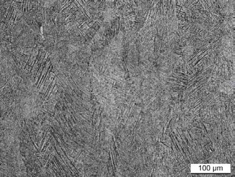
transformation during the cooling, and from which the α -colonies and α -laths nucleate and grow.
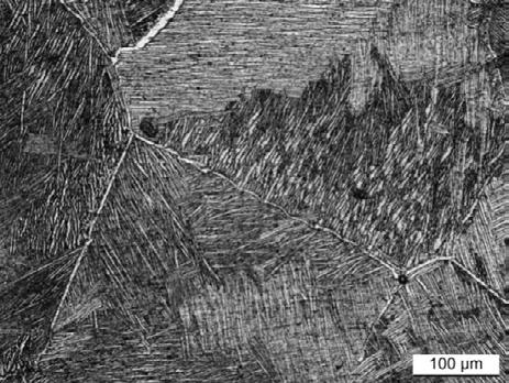
(a) (b)
Fig.1 - Microstructure of the L-PBF Ti6Al4V alloy after heat treatment a) at 740°C -130min and b) at 1050°C – 60 min. / Microstruttura della lega LPBF Ti6Al4V dopo trattamento termico a) a 740°C –130min e b) a 1050°C – 60 min.
Fig. 2a illustrates the cross-section of the AlCrN film onto the substrate. The AlCrN film also follows the profile of both smooth and rough substrates with no microstructural alteration in the near surface region of the substrates. The coating consists of a (2.9±0.2) μ m thick layer made of densely packed, slightly tapered columnar grains identifiable in the fracture surface of the coating deposited onto a silicon wafer in fig. 2b.
The AlCrN film is compositionally uniform. Quantitative
analysis based on EDX spectra acquired on the fractured section of the AlCrN film indicates an Al fraction of 0.61±0.01. In terms of micromechanical properties, the AlCrN film, irrespective of the heat treatment condition of the substrate, is characterized by hardness values around 33 – 34 GPa which are quite consistent with the values listed in the literature for AlCrN films with Al fractions of 70% and 60%, respectively (13).
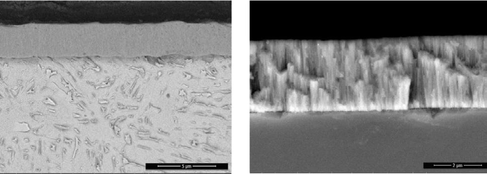
Fig.2 - Section of the AlCrN coating a) at low magnification and b) showing the columnar grains in a fracture surface of the coating deposited on a silicon wafer. / Sezione del coating AlCrN a) a basso ingrandimento e b) che mostra i grani colonnari in una superficie di frattura del coating depositato su un wafer di silicio. (a) (b)
The scratch failure mode of the AlCrN film can be described, first, as the chipping off the side of the scratch track of the outer part of the coating. The spalled areas became progressively larger with increasing the load, until they extended across the entire width of the track. Then, at the delamination load, the entire coating was spalled off and the substrate was detected. Actually, the initial chipping failure never occurred at the coating/substrate interface. Infact, cracks proceeded transversely along the columnar grain boundaries, crossing part of the coating
thickness and were deflected along a longitudinal path above the substrate interface. This means that the layer also possessed rather good adhesion to the substrate, so that initial failure is of a cohesive nature, and complete coating removal occurs only at a later stage.
Thus, it is concluded that, using the L-PBF Ti6Al4V substrates (especially when subjected to the lowertemperature heat-treatment at 740 °C), the adhesion strength is comparable to or significantly competitive with the adhesion of conventionally manufactured substrates.
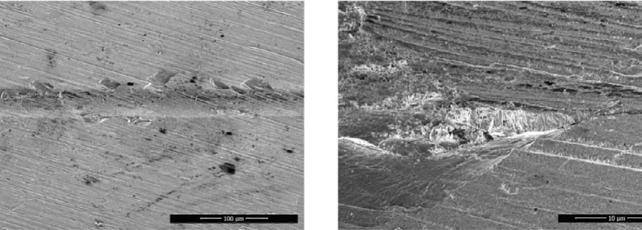
Fig.3 - SEM micrographs a) of a part of the scratch track and b) a magnified view of a detail. / Micrografie SEM a) di una parte della traccia di scratch e b) di una vista ingrandita di un dettaglio.
Concerning the results of the VDI tests, the AlCrN films predominantly exhibited cracks (fig. 4a). The different substrate-coating combinations did not influence the inter-crack spacing in the AlCrN films, which remained constant at around 15 μ m in all samples. The same failure modes observed in the scratch test were also triggered by the VDI test, which means that both tests elicited
similar damage mechanisms, although the VDI test is less sensitive to differences in adhesion/cohesion strength. FIB cross-sections of the VDI failures confirm that cracks in the AlCrN film were deflected in the longitudinal direction shortly above the substrate (fig. 4b) which testifies to its good interface toughness.
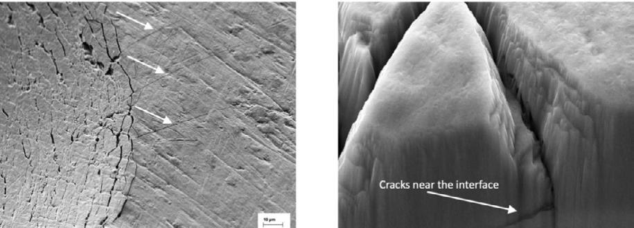
Fig.4 - SEM micrographs showing a) cracks after the Rockwell indentation for the VDI test and b) cracks near the interface. / Micrografie SEM che mostrano a) cricche dopo l’indentazione Rockwell per il test VDI e b) cricche vicino all’interfaccia.
In this work, we studied the properties of the AlCrN thin film deposited onto a Ti4Al6V alloy substrate fabricated by Selective Laser Melting. The focus was on how two post-process heat treatments of the substrate and its surface finish affected the adhesion and sliding wear performance of the film. The following conclusions can be drawn: i) the roughness of the substrate had little effect on scratch adhesion and the film exhibited better scratch adhesion on harder substrates (the hardness depends on the heat treatment); ii) the adhesion strength
is comparable to or significantly competitive with the adhesion of conventionally manufactured substrates; iii) the same failure modes observed in the scratch test were also triggered by the VDI test, which means that both tests elicited similar damage mechanisms.
[1] Kruth JP, Dadbakhsh S, Vrancken B, Kempen K, Vleugels J, Van Humbeeck J. Additive Manufacturing of Metals via Selective Laser Melting: Process Aspects and Material Developments, in: T.S. Srivatsan, T.S. Sudarshan (Eds.), Additive Manufacturing: Innovations, Advances, and Applications, CRC Press (USA) 2016; 69–99.
[2] Dutta B, Froes FH. Markets, Applications, and Costs, in: Additive Manufacturing of Titanium Alloys, Elsevier 2016; 61–73.
[3] Dutta B, Froes FH. The Additive Manufacturing of Titanium Alloys, in: Additive Manufacturing of Titanium Alloys, Elsevier, 2016; 1–10.
[4] Dutta B, Froes FH. Microstructure and Mechanical Properties, in: Additive Manufacturing of Titanium Alloys, Elsevier, 2016; 41–50.
[5] Sun S, Brandt M, Easton M. Powder bed fusion processes, in: M. Brandt (Ed.), Laser Additive Manufacturing, Elsevier, 2017; 55–77.
[6] Thijs L, Verhaeghe F, Craeghs T, Van Humbeeck J, Kruth JP. A study of the microstructural evolution during selective laser melting of Ti–6Al–4V. Acta Materialia 58, 2010; 3303–3312.
[7] Etesami SA, Fotovvati B, Asadi E. Heat treatment of Ti-6Al-4V alloy manufactured by laser- based powder-bed fusion: Process, microstructures, and mechanical properties correlations, a. J. All. Comp. 895, 2022; 162618.
[8] Ronkainen H, Koskinen J, Varjus S, Holmberg K. Load-carrying capacity evaluation of coating/substrate systems for hydrogen-free and hydrogenated diamond-like carbon films. Tribology Letters 6, 1999: 63–73.
[9] Wang CT, Hakala TJ, Laukkanen A, Ronkainen H, Holmberg K, Gao N, Wood RJK, Langdon TG. An investigation into the effect of substrate on the load-bearing capacity of thin hard coatings. J. Mat. Sci. 51, 2016; 4390–4398.
[10] Budinski KG. Tribological properties of titanium alloys. Wear 151, 1991;203–217.
[11] Cerri E, Ghio E, Bolelli G. Ti6Al4V-ELI Alloy Manufactured via Laser Powder-Bed Fusion and Heat-Treated below and above the β-Transus: Effects of Sample Thickness and Sandblasting Post-Process. Applied Sciences. 12, 2022; 5359.
[12] VDI 3198, in: Verein Deutscher Ingenieure Normen, VDI-Verlag, Düsseldorf, Germany, 1991.
[13] Chen Y, Xu YX, Zhang H, Wang Q, Wei T, Zhang F, Kim FH. Improving high-temperature wear resistance of arc-evaporated AlCrN coatings by Mo alloying. Surface and Coatings Technology 456, 2023; 129253.
Le proprietà meccaniche e la microstruttura di coating sottili, depositati su substrtati di Ti6Al4V prodotti per Selective Laser Melting, sono stati analizzati. In dettaglio, il lavoro è focalizzato su come le resistenze meccaniche e la rugosità superficiale del substrato ha influlenzato le performance del coating depositato per mezzo di High-Power Impulse Magnetron Sputtering (HiPIMS). I substrati di Ti6Al4V sono stati fusi selettivamente da un laser, trattati termicamente sia a temperature inferiori che superiori alla β -transus, lappati con differenti carte abrasive per avere superfici lisce e ruvide, e rivestiti con un coating di AlCrN.
L'adesione ottenuta da test di scratch su superfici più dure, trattate al di sotto del β -transus, è stata maggiore, mentre la finitura del substrato aveva un effetto trascurabile. Al contrario, nei test di usura ball-on-disc, la rugosità del substrato ha avuto un effetto dominante: le superfici ruvide hanno sempre provocato cricche premature e delaminazioni del rivestimento. La microstruttura è stata studiata mediante microscopia elettronica a scansione e microscopia ottica per studiare l'area della sezione trasversale e la topografia del rivestimento.
E. Ferrari, S. Gaiani, M. Gozzi, M. Lassinantti Gualtieri, F. Mantovani, G. Ponzoni, P. Veronesi
Additive manufacturing has become a prominent solution for producing intricate components with complex geometries. Titanium alloy Ti-6Al-4V is widely used in additive manufacturing due to its excellent mechanical properties, low density, and corrosion resistance. However, residual stresses generated during the laser powder bed fusion (LPBF) process require specific heat treatments. This research aims to determine the optimal temperature-time parameters of thermal cycles able to reduce residual stresses while achieving desired microstructural conditions. Previous research investigated the impact of heat treatments at different temperatures, with annealing at 800°C and 835°C for 2 hours resulting in the best mechanical properties. The samples treated at 800°C exhibited increased ductility due to the onset transformation of α ’ to α + β . The samples treated at 835°C showed a favorable balance between mechanical properties and plasticity. This study expands on the previous research by comparing different treatment times at optimal temperatures and investigating their effect on average mechanical properties and their variance. Complete mechanical and microstructural characterization, including XRD analysis, was conducted on the treated samples.
KEYWORDS: ADDITIVE MANUFACTURING, TI-6AL-4V, STRESS RELIEF, HEAT TREATMENT STRATEGIES, MICROSTRUCTURE
Additive manufacturing techniques, such as laser powder bed fusion (LPBF), have revolutionized the production of components by providing remarkable mechanical properties. The rapid solidification rates achieved during the LPBF process contribute to these properties. However, the rapid and repeated cooling involved in the process results in high levels of residual stresses in the printed parts, which can lead to distortions and surface defects upon removal from the building platform [1]. To optimize the microstructure and mechanical properties of materials, it is common practice to postprocess almost all additive manufacturing parts, by proper heat treatments, before their removal from the building platform.
Extensive research has been conducted on postprocess heat treatments of Ti-6AI-4V components manufactured using LPBF technology [2]. The objective of these studies is to identify optimal heat treatment cycles that
E. Ferrari, M. Gozzi
Veca SpA, Italy elisa.ferrari@veca.it marica.gozzi@veca.it
S. Gaiani
V System, srl. Italy silvia.gaiani@vsystem.it
M. Lassinantti Gualtieri, P. Veronesi
Università degli Studi di Modena e Reggio, Italy magdalena.gualtieri@unimore.it paolo.veronesi@unimore.it
F. Mantovani, G. Ponzoni AMT srl, Italy flavia.mantovani@amt-srl.com greta.ponzoni@amt-srl.com
effectively eliminate residual stresses and achieve a proper microstructural balance. The generation of residual stresses is attributed to the expansion and contraction interactions between layers induced by the large thermal gradients inherent in the LPBF process, where a laser spot scans the surface and induces localized melting.
The typical microstructure of Ti-6Al-4 V alloys obtained by LPBF consists of an extremely fine acicular martensitic structure known as the alpha prime ( α ') phase [3]. This microstructure is a result of the extremely fast heating and cooling rates typical of the LPBF process. Additionally, the as-built microstructure of LPBF components usually consists of an acicular martensitic phase within columnar β grains, exhibiting a pronounced orientation along the building direction [4]. The inclination of the martensitic needles at an angle of approximately 45 degrees with respect to the manufacturing direction is a characteristic feature [5]. These microstructural characteristics contribute to the high yield strength (>1000 MPa), high ultimate tensile strength, and elongations in the range of 7-10% observed in LPBF Ti-6Al-4V components [6]. It should be noted that the reduction in the ductility of parts is not necessarily observed throughout the entire thickness of the built part but rather depends on its shape, scanning strategy, and other factors. A literature review indicates that while the yield and tensile strengths of LPBF components are significantly greater than the ASTM specifications for the biomedical or aerospace sector, the reported values for tensile strain often fall below the minimum needed.
The width of the α or α ' phase plays a significant role in determining the strength of LPBF-fabricated lamellar structures. The effective slip length for dislocation is limited to the individual martensite width rather than the α colony size [7]; hence, controlling the dimension of the alpha phases is crucial for achieving the desired strength. Consequently, postprocessing heat treatments are designed not only to eliminate residual stress but also to control the size of the alpha phases, as a Hall-Petch relationship exists between the width of the alpha phases and the strength of the material.
Numerous studies have been conducted to investigate the
effect of different postprocess heat treatment strategies on the mechanical properties and microstructural evolution of LPBF Ti6Al4V alloy components. These studies have explored various temperatures, holding times, and cooling rates to optimize the process parameters and achieve excellent mechanical properties and good ductility. However, the decomposition kinetics of alpha prime ( α ') martensite and the precise optimization of process parameters require further research and deeper insights [8][9][10][11][12].
In the industrial manufacturing of LPBF Ti6Al4V components, post-heat treatments also aim to minimize the variability of the mechanical properties within the same build [13]. As a matter of fact, a more robust postprocess treatment would also help designers in selecting the proper minimum expected mechanical properties. LPBF processes are influenced by various factors that can lead to deviations in mechanical properties, even within the same build [14]. These deviations can be reduced through carefully designed heat treatments that induce microstructural modifications. Hot Isostatic Pressing (HIP) [15] is known to help decreasing the porosity of parts and is considered as a reliable process for improving the tensile performance and modifying the microstructure at elevated temperatures [16]. However, HIP alters the microstructure by inducing coarse lamellar α and β formation, resulting in a negative impact on strength despite reducing porosity and increasing elongation [17].
In a previous work by the authors [30] it was demonstrated that by applying a proper post-heat treatment for LPBF Ti6Al4V parts, the exceptional mechanical properties associated with the fine microstructure typical of LPBF can be preserved, while minimizing the variability of the mechanical properties within the same build. In that work, comprehensive analyses were performed to better understand the effects of post-heat treatments on LPBF Ti6Al4V components. It was found that the sub betatransus heat treatment at 830°C for 2 hours retained the excellent mechanical properties of the as-built samples while increasing elongation and reducing variance among samples from different locations within the same building. The study also investigated the impact of temperature on the mechanical properties, noting a modification in
the mechanical properties and elongation and, more importantly, presenting a lower variance within samples belonging to the same build but with a different part location. This study aims to select an annealing condition at this temperature able to provide high strength, good ductility, and a uniform distribution of characteristics across the entire printing area.
This new study aims to analyze the influence of heat treatment time, using as a reference the two bestperforming treatments from the previous research [30], namely, single annealing cycles at 800°C and 835°C for two hours. These two treatments will be compared with thermal cycles performed at the same temperature but with a doubled treatment time, i.e., 4 hours. This study serves to thoroughly understand how to optimize the heat treatment process to achieve a more robust result and achieving the maximum material properties despite possible bias introduced for instance by part location in the building chamber or different LPBF units.
For the present study, two samples with different shapes (circular and rectangular cross section) were manufactured using 3 different LPBF units of the same brand. Specimens extracted from different positions of the builds were subjected to various heat treatment cycles (C1-C4, described later in section 2.2.).
The cylindrical samples had a diameter of 10 mm and a height of 120 mm whereas the rectangular samples had the dimensions 20x13x3.5 mm. Both types of samples were built in the vertical direction.
For the thermal cycles C1 and C2, sets of 30 cylindrical samples were built using an EOS M290 LPBF unit. Six different part locations on the building platform were sampled: the corners at a 10 mm distance from the platform edges, and in the central position at two symmetrical positions spaced 100 mm along the y direction.
For the thermal cycle C3, sets of 3 samples with rectangular cross section were built using a EOS SI2051 LPBF unit. For C4 sets of 20 cylindrical samples, were manufactured using an EOS SI3826 LPBF unit. All builds were accomplished using a virgin commercial Ti-6Al-4V powder from ELI EOS GmbH Electro Optical Systems.
The same process parameters were used in all units, namely:
• Average powder grain size: D90 (48–51 µ m);
• Source power: 340 W (single laser source);
• Printing speed: 1250 mm/s;
• Spot size: 80 μ m;
• Layer thickness 50 μ m
In the present study, three different post-process vacuum heat treatment strategies were considered and investigated (Table 1).
Tab.1 - Heat treatment cycles used in this paper.
+ Ar flux Vacuum Oven
C3 835°C 2h Constant cooling rate 11°C/min + Ar flux Vacuum Oven
C4 835°C 4h Constant cooling rate 11°C/min + Ar flux Vacuum Oven
This treatment strategy is a single annealing thermal cycle. The thermal cycles were performed at two different temperatures, above 780 °C, but always below β transus transition temperature to avoid excessive grain growth. Operating at these temperatures, an α prime transformation is expected and will theoretically be more relevant as
temperature increases. The expected advantages are an increased homogeneity of mechanical response and increased elongation at break and ductility, while the higher temperature could have a detrimental effect on the peak mechanical properties (UTS and Rp0.2); In order to have a better understanding of the impact of
different heat treatment strategies on Ti-6Al-4V alloy, some samples in the “as built” condition have also been tested as a reference of initial basic properties that can be obtained directly via the LPBF process. All heat treatments have been conducted on a TAV vacuum unit H6 S, having chamber dimensions of 600 x 600 x 900 mm and maximum Ar pressure during cooling of 11.5 bar. Heat treatment has been performed using a charge thermocouple, i.e., a thermocouple positioned in contact with one of the samples, where a 1 mm diameter hole, 20 mm deep, had been drilled to fix the K-type thermocouple in place.
The samples heat treated with the different strategies discussed in Section 2.2 were characterized by means of micro-hardness test, tensile tests, microstructural examination with optical microscope, and microstructural phase determination with X-ray Diffraction (XRD).
Tensile tests were performed in accordance with standard EN ISO 6892-1:2016 and using fully machined cylindrical specimens with L0 = 20 mm and D0 = 4 mm. The tests were performed using the constant strain rate method (A1 mode with closed-loop control). Five tests at room temperature were performed for each set of samples subjected to the heat treatment strategy shown in Table 1, using a hydraulic universal press Instron 5982 with 100 kN maximum load;
For optical micrographic analysis, samples were mechanically grounded using SiC grinding paper and then polished with colloidal silica (0.04 μ m) and hydrogen peroxide (30%). Kroll reagent (5 mL HNO3; 10 mL HF; 85 mL H2O) was used as an etchant. Samples were then analyzed using a Nikon Eclipse LV150-NL optical microscope and fluoride lenses. Higher magnification observations were performed using scanning electron
microscopy (ESEM Quanta-200 Fei, Hillsboro, OR, USA, and SEM Nova NanoSEM 450–FEI).
X-ray Diffraction (XRD) data were collected in Bragg–Brentano configuration using an X'Pert PRO multipurpose diffractometer (PANalytical, Almelo, The Netherlands) equipped with a Real-Time Multiple Strip (RTMS) detector. The Cu-K radiation emitted from the X-ray tube at 40 kV and 40 mA passed through fixed divergence and anti-scatter slits (both 0.5°) as well as a soller slit (0.04 rad) before interacting with the sample. The beam width was adjusted using a mask of 10 mm. The diffracted beam pathway included a Ni filter, a soller slit (0.04 rad), and an anti-scatter blade (5 mm). Data were collected in the angular range 10–120° 2 θ using a step size of 0.0167° and 40 s/step. Phase identification was accomplished with the aid of the X'Pert Highscore plus software (2.0, PANalytical B.V., Almelo, The Netherlands) implemented with the PDF2 database.
Microhardness tests were accomplished using a Wilson VH1202 microhardness tester with a load of 0.5 kg. The impressions were made with a dwell time of 12 seconds. Before measurements, samples were subjected to metallographic preparation mounted using a Struers model Citopress-5 and polished using a Struers model Laboforce 100 lapping machine. Five tests at room temperature were performed for each set of samples subjected to the heat treatment strategy shown in Table 1
In this section, a concise description of the experimental results and their interpretation will be provided.
The results of tensile tests performed on samples along the growth direction (Z direction) are summarized in Table 2.
- Tensile test result and graphic.
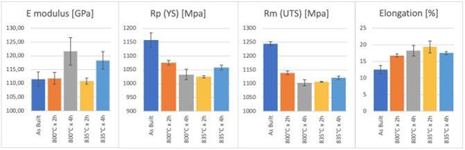
The high tensile strength and low ductility of as built samples is ascribable to their complete martensitic α′ microstructure, as opposed to the predominant α + β typical of annealing-treated samples. α/α′ with hexagonal close-packed (hcp) crystal structure possesses a smaller number of slip systems than bcc β . Additionally, more V element in α′ rises solid strengthening effect and blocks the dislocation movement, therefore a greater force is required and less deformation occurs when fracture happens. The samples heat-treated at 800°C and 850°C for 4 hours and cooled in air contain the most β and the finest lamellar α , and as expected they exhibit the best ductility and acceptable ultimate tensile strength values. As amatter of fact, a large volume fraction of β in Ti6Al4V alloy leads to a low tensile strength and good ductility. A smaller size of lamellar α + β in annealing-treated samples indicates higher tensile strength according to the Hall-Petch relationship.
As far as the tensile tests results are concerned, as shown in table 2 and relevant charts, the two additional hours of treatment have different effects with respect to the different parameters analyzed. Considering the effects of the investigated heat treatments, the following trends can be evidenced:
• Young's modulus (E) was calculated for all specimens in the range of 400-800 MPa, and for this parameter it can be seen that 2 additional hours at the treatment temperature brings an increase of 10 and 8 GPa, respectively, although, on the other hand, the standard deviation is almost tripled for both cycles. This result is in agreement with literature results, ascribing the lower values of the Young’s modulus to the texturing deriving from L-PBF [31]. During solidification, the bcc β phase preferentially grows in the <100> direction, giving rise to long, columnar prior β grains. The <100> direction of each of these columnar grains
is thus oriented quasi parallel to the build direction, and the rotation of the grain around this direction is considered to be random, causing the presence of a fiber-like texture. [32]
• Concerning the yield strength (Rp), it can be seen that two hours of additional heat treatment have different effects depending on the temperature. At 800°C increasing from 2 to 4 hours leads to a lowering of the nominal Rp values and also to a higher standard deviation, which becomes almost two times the standard deviation obtained with the 2-hour treatment. For the 835°C treatment, on the other hand, the 4-hour treatment seems to improve over the 2-hour treatment, but only for the nominal value of Rp; in fact, the standard deviation of the data, increasing from 2 to 4 hours treatment time, leads to a 4-times increase.
• The same trend occurs for the Ultimate tensile strength (Rm) values: for the 800°C treatment, the additional two hours are detrimental, while for the 835° treatment the additional two hours lead to a moderate increase. Again, the standard deviation, when passing from 2 to 4 hours, increases significantly, regardless of temperature.
• For the elongation values, on the other hand, the trend seems to affect both the nominal values and the dispersion of the data. At 800°C the 4-hour treatment confers 2 percentage points more to the nominal elongation value, increasing the standard deviation by about 3 times. For the treatment at 835°C, on the other hand, the 4-hour treatment is about 2 percentage points worse than the 2-hour treatment, but a very low standard deviation can be seen, about onethird that of the shorter treatment; this indicates the achievement of higher homogeneity in the sample.
Micrographic examination
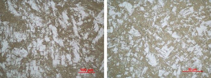
Fig.1 - OM micrographs of Ti-6Al-4V following C1 single annealing th.ermal cycle at 800°C x 2h, magnification 200x and 500x.
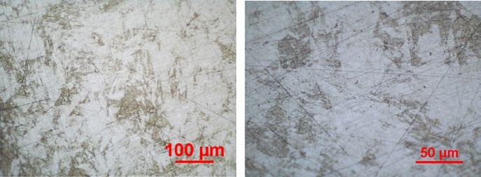
Fig.2 - OM micrographs of Ti-6Al-4V following C3 single annealing thermal cycle at 800°C x 4h, magnification 200x and 500x.
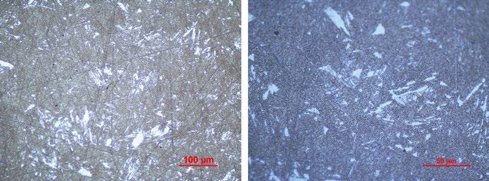
Fig.3 - OM micrographs of Ti-6Al-4V following C2 single annealing thermal cycle at 835°C x 2h, magnification 200x and 500x.
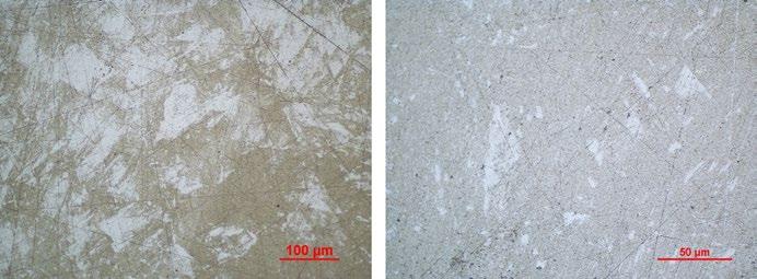
Fig.4 - OM micrographs of Ti-6Al-4V following C4 single annealing thermal cycle at 835°C x 4h, magnification 200x and 500x.
In the figures, a comparison in a different magnification of various individual annealing cycles conducted on the samples is presented.
The figures clearly depict that the resulting microstructure in all heat-treated samples consists primarily of an α acicular phase. In these microstructures, the fine α prime needles, generated due to a sequence of rapid heating and cooling cycles typical of the LPBF process, are still visible, despite the heat treatment. This phenomenon of martensitic structure creation occurs because the high cooling rates used in LPBF processing deplete the vanadium content present in the material matrix; this element is a strong β stabilizer for the titanium alloys, and its absence allows for the formation of α prime. When examining the cycle carried out at 800°C for 2 hours and 4 hours, notable discrepancies emerge, particularly in terms of the extent of transformation of the prior alpha prime phase. Specifically, the transformation is more pronounced in the latter case, where the samples were subjected to an additional two-hour annealing process at 800°C. Furthermore, this prolonged treatment results in a more homogeneous structure, with the alpha phase being uniformly arranged in more coarsed grains. Similar observations can be made for the treatment performed at 835°C, although there are not such marked differences. This can be attributed to the fact that the higher treatment temperature already promotes the transformation process during the first two hours, thereby diminishing the influence of the treatment time parameter compared to the cycle performed at a lower temperature.
Figure 5 shows XRD data collected from the specimens exposed to the various heat treatments (C1-C4). The full angular range (a) is shown together with a limited one (b). The main hcp phase is indexed according to space group P63/mmc [33]. The positions of observed reflections assigned to body-centered cubic β -phase (space group Im-3m [34]) are indicated, and the main one is better pictured in the limited angular region shown in Figure xb. Distinguishing between alpha and alpha prime phases is challenging as both of them exhibit the same hexagonal structure [35]. However, comparative evaluations based on the ratio between the cell parameters c and a can give
some indications on the presence of martensite. Hence, this parameter was determined using the angular positions of the hcp reflections and the results are shown in Figure Xc. Data for the as-received powder was also included in this plot [30].
The shift of the peak suggests the absorption of vanadium by the cell, leading to an enlargement of the cell. One answer could be that, in the face of a massive transformation of the alpha prime phase, vanadium has undergone diffusion phenomena within the cell.
The c/a ratio is higher for the annealed samples with respect to the powder [30]. An important increase in the ratio is observed following prolonged annealing at 835 °C, indicating a more important heat-induced transformation from alpha to alpha prime (microstructural modification).
The temperature of 835°C is far from both that of beta transus (996°C) and at that of solubilization (about 960°C), so we cannot speak of a phase transformation, but of a solid-state transition from alpha prime to alpha
In order to better understand the transformations occurring during the heat treatment, it is useful to identify some relevant temperature ranges, as suggested by Ter Haar ed Al. [36]. In this paper, the understanding of the mechanism of grain morphology transformation in the solid solution temperature region (SSTR) is linked to three main regions: heat treatments conducted in the low-, medium- and high-SSTR. While the low and medium are useful to determine the annealing strategy for decomposing α ’ into a stable dual phase lamellar α + β microstructure, the high-SSTR is used when describing the fragmentation and globularisation to achieve more equiaxed primary α -grains, which is outside of the scope of this paper.
A slightly modified version of their graph is shown in Figure 6, where the temperatures used in this study are indicated by arrows, and help understanding the criteria used to select the heat treatment strategy used during this research.
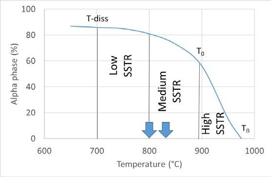
Fig.5 - Schematic of temperature regions and key temperatures in the SSTR (Solid Solution Temperature Region) vs estimated alpha phase fraction [adapted from 36].
Within this solid solution in the aforementioned study, the α -phase served as the solute, while the β -phase acted as the matrix. The SSTR, in this context, encompassed the temperature range between the dissolution temperature (Tdiss) and the β -transus temperature (T β ). The dissolution temperature was identified as the point at which the β -phase began to exponentially increase in volume percentage as a result of the dissolving of the α -phase into the β -phase. For the purposes of the study of Ter Haar ed Al. [36], the dissolution temperature was determined to be 705 °C.
Furthermore, the SSTR was divided into three distinct regions: low-, medium-, and high-SSTR. The low- and
medium-SSTRs were situated below a critical temperature (T0), while the high-SSTR lay above T0. The critical temperature denoted the temperature above which α ' phase formation occurs during rapid cooling (water— WQ or air cooling—AC). Based on thermodynamic data T0 was calculated to be 893 °C and 872 °C, respectively.
The low- and medium-SSTR regions were separated by a temperature range recognized by various researchers as the region where α ' decomposes into α upon heating, yielding favorable tensile results.
The heat treatments used in this study were designed to emphasize the impacts of dwell temperature and dwell time.
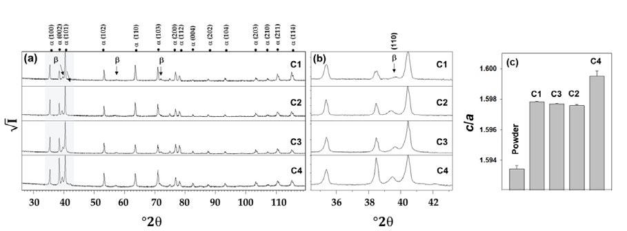
Fig.6 - XRD data collected from annealed samples: 800 °C for 2h (C1); 800 °C for 4h (C2); 835 °C for 2 h (C3); 835 °C for 4h (C4). The full angular range is shown in (a) whereas a limited one is shown in (b), the latter aimed at better visualize the strongest reflection of the β -phase. In (c), the c/a ratio of the hexagonal phase ( α/α ’) in the annealed samples is shown together with data for the as-received powder (previously published [30]).
During the creation of the specimen, the cooling time is so fast that the resulting structure can only be the alpha prime, which is a metastable solid solution composed of alpha phase and beta phase. The lattice structure of the alpha prime is HCP, but due to the presence of the beta phase elements (i.e., vanadium), the HPC cell packing factor of the alpha prime is very low.
The low packing factor indicates that the structure will have a narrow and wide shape.
The moment I go to perform annealing treatments between the transformation start temperature (about 760°C) and the beta transus temperature (about 996°), the alpha prime starts to separate into alpha a and beta. As the kinetics of the transition can be assumed that the vanadium begins to leave the HCP cell, which thus become alpha phase (with
a long and narrow HCP cell) and go to the grain boundary , with a BCC cell.
800° is a temperature that does not allow one to see much improvement from the point of view of beta phase transformation between 2 and 4 hours, but only an enlargement of the grain. This would also explain the improvement in elastic modulus.
835, on the other hand, is a temperature at which the improvement from 2 to 4 hours can be appreciated, because, as can be seen from the c/a graph, the C4 treatment leads to a noticeable conversion of the alpha prime phase, with a noticeable increase in the beta phase.
hardness
- Micro hardness test result and graphic.
Microhardness test results
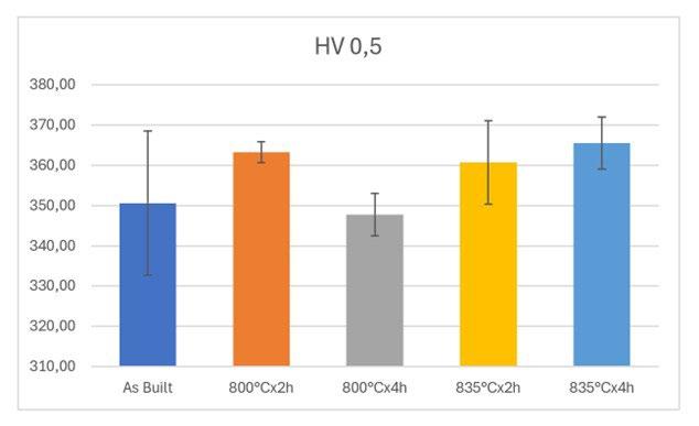
The results of the microhardness analyses follow the trend of the tensile tests for the parameters Rp and Rm. For the treatment carried out at 800°C, the best dwell time is the 2-hour dwell time, as the 4-hour dwell time both depresses the nominal hardness value and increases the
inhomogeneity of the data by about 5 times.
For the heat treatment carried out at 835°C, on the other hand, two more hours of dwell time is ameliorative in that it increases the hardness by about 5 percent, going on to slightly increase the standard deviation of the datum.
This work aims to analyze the different effects of residual stress reduction treatments performed on Gr. 5 titanium specimens obtained by additive manufacturing. Specifically, the main objective of the research is to investigate the influence of the heat treatment time on the material properties, starting from the results obtained from the previous study [30], where two temperature ranges (800°C x 2h and 835°C x 2h, respectively) had been identified and had provided encouraging results both in terms of mechanical properties and homogeneity of the values obtained within the same job.
With this premise in mind, the heat treatment time was then extended, leaving all other test conditions unchanged, to a total duration of 4h with the aim of verifying whether this strategy could allow further improved results over those previously obtained.
The main purpose of the stress relief treatments performed on Ti 6Al 4V parts obtained by additive manufacturing is to maximize the strength response of the material but also to obtain a homogeneous result on all the samples grown in different positions of the printing area.
Looking at the results obtained by increasing the dwell time to 4h total, it can be observed that:
• Comparing the results of the two different dwell times of 2h and 4h at T 800°C, respectively, it can be seen that the results of the mechanical properties are not improved at all by increasing the dwell time in the furnace; both the unit yield strength and the unit tensile strength are lower, and the standard deviation is also worsened. This result is also confirmed by the microhardness tests, where the distribution of results is extremely scattered
• Conversely, for the samples treated at 835 °C, prolonging the treatment time to 4h marks an increase in mechanical properties around 3-4%, although the standard deviation of the results is worsened, as is the elongation at break. The result of the tensile tests is again confirmed by the microhardness trend, which in this case is higher for the longer duration treatment
Micrographic examination revealed that all heat-treated samples exhibited a predominantly α acicular phase. The presence of α prime needles, characteristic of the LPBF
process, was still observed despite the heat treatment. The transformation of the alpha prime phase was more pronounced with the 4-hour treatment at 800°C, leading to a more homogeneous structure. Similar observations were made for the treatment at 835°C, although the differences were less noticeable due to the higher treatment temperature.
XRD analysis confirmed the presence of the hcp phase and indicated the absorption of vanadium by the cell, resulting in an enlargement of the cell. The c/a ratio, which provides insights into the presence of martensite, increased with prolonged annealing at 835°C, indicating a significant heat-induced transformation from alpha to alpha prime.
It has been repeatedly discussed in the literature how the optimal treatment parameters for Ti 6Al 4V alloy must exhibit a balance of process temperature and thermal cycle duration parameters. This paper, together with the previous paper by some of the authors, basically show two main results:
• It is necessary to choose a treatment temperature > 780°C (see fig 6) in order to achieve an initial alpha prime transformation in industrial-compatible cycles. The best results in terms of general mechanical properties and, above all, homogeneity of results was obtained with the samples treated @835°C, although those treated at @800°C, i.e. in the low range of the medium SSTR, had already appreciable properties although slightly more dispersed
• Conversely, the treatment time turned out to be a variable that was not so significant, and indeed, in the case of the treatment @800°C for 4h, the results turned out to be worse than the results obtained with shorter times.
An interesting result obtained from the present study by analyzing the data from the treatments with a duration of 4h is the significant increase recorded in the elastic modulus of the material, which is almost 10% higher than the values previously found on this alloy. A scientific explanation for this result, possibly related to texturing, cannot be given at present, and it will be further investigated and deepened in the future by generating samples with different orientations.
In conclusion, this study contributes to the understanding of the effects of different heat treatment strategies on the alloy and provides valuable insights for optimizing the
post-process heat treatment of additively manufactured titanium components.
[1] Mercelis, P.; Kruth, J. Residual stresses in selective laser sintering and selective laser melting. Rapid Prototyp. J. 2006, 12, 254–265.
[2] Bartolomeu, F.; Gasik, M.; Silva, F.S.; Miranda, G. Mechanical Properties of Ti6Al4V Fabricated by Laser Powder Bed Fusion: A Review Focused on the Processing and Microstructural Parameters Influence on the Final Properties. Metals 2022, 12, 986.
[3] Yang, J.; Yu, H.; Yin, J.; Gao, M.; Wang, Z.; Zeng, X. Formation and control of martensite in Ti-6Al-4V alloy produced by selective laser melting. Mater. Des. 2016, 108, 308–318.
[4] Antonysamy, A.A.; Meyer, J.; Prangnell, P.B. Effect of build geometry on the β -grain structure and texture in additive manufacture of Ti6Al4V by selective electron beam melting. Mater. Char. 2013, 84, 153–168. [CrossRef]
[5] Yassine, L.; Connétable, D.; Hugues, J.; Hermantier, P.; Barriobero-Vila, P.; Dehmas, M. Microstructural evolution during post heat treatment of the Ti–6Al–4V alloy manufactured by laser powder bed fusion. J. Mater. Res. Technol. 2023, 23, 1980–1994.
[6] Etesami, S.A.; Fotovvati, B.; Asadi, E. Heat treatment of Ti-6Al-4V alloy manufactured by laser-based powder-bed fusion: Process, microstructures, and mechanical properties correlations. J. All. Comp. 2022, 895, 162618. [CrossRef]
[7] Xu, W.; Lui, E.W.; Pateras, A.; Qian, M.; Brandt, M. In Situ Tailoring Microstructure in Additively Manufactured Ti-6Al-4V for Superior Mechanical Performance. Acta Mater. 2017, 125, 390–400. [CrossRef]
[8] Cao, S.; Zou, Y.; Lim, C.V.S.; Wu, X. Review of Laser Powder Bed Fusion (LPBF) Fabricated Ti-6Al-4V: Process, Post-Process Treatment, Microstructure, and Property. Adv. Manuf. 2021, 2, 20. [CrossRef]
[9] Ter Haar, G.M.; Becker, T.H. The influence of microstructural texture and prior beta grain recrystallisation on the deformation behaviour of laser powder bed fusion produced Ti–6Al–4V. Mater. Sci. Eng. A 2021, 814, 141185. [CrossRef]
[10] Cao, S.; Hu, Q.; Huang, A.; Chen, Z.; Sun, M.; Zhang, J.; Fu, C.; Jia, Q.; Lim, C.V.S.; Boyer, R.R.; et al. Static coarsening behavior of lamellar microstructure in selective laser melted Ti–6Al–4V. J. Mater. Sci. Technol. 2019, 35, 1578–1586. [CrossRef]
[11] Yan, X.; Chen, C.; Huang, C.; Bolot, R.; Kuang, M.; Ma, W.; Coddet, C.; Liao, H.; Liu, M. Effect of heat treatment on the phase transformation and mechanical properties of Ti6Al4V fabricated by selective laser melting. J. Alloys Compd. 2018, 764, 1056–1071. [CrossRef]
[12] Khorasani, A.M.; Gibson, I.; Goldberg, M.; Littlefair, G. On the role of different annealing heat treatments on mechanical properties and microstructure of selective laser melted and conventional wrought Ti-6Al-4V. Rapid Prototyp. J. 2017, 23, 295–304. [CrossRef]
[13] Ghods, S.; Schur, R.; Schleusener, R.; Montelione, A.; Pahuja, R.; Wisdom, C.; Arola, D.; Ramulu, M. Contributions of Intra-Build Design Parameters to Mechanical Properties in Electron Beam Additive Manufacturing of Ti6Al4V. Mater. Today Commun. 2022, 30, 103190. [CrossRef]
[14] Charles, A.; Elkaseer, A.; Thijs, L.; Scholz, S. Effect of build platform location and part orientation on dimensional accuracy of downfacing surfaces in LPBF. In Proceedings of the Conference: World Congress on Micro and Nano Manufacturing 2021, Bombay, Mumbai, India, 21–23 September 2021.
[15] Yang, Z.; Yang, M.; Sisson, R.; Li, Y.; Liang, J. A machine-learning model to predict tensile properties of Ti6Al4V parts prepared by laser powder bed fusion with hot isostatic pressing. Mater. Today Commun. 2022, 33, 104205.
[16] Ettefagh, A.H.; Zeng, C.; Guo, S.; Raush, J. Corrosion behavior of additively manufactured Ti-6Al-4V parts and the effect of post annealing. Addit. Manuf. 2019, 28, 252–258
[17] Qiu, C.; Adkins, N.J.E.; Attallah, M.M. Microstructure and Tensile Properties of Selectively Laser-Melted and of HIPed LaserMelted Ti–6Al–4V. Mater. Sci. Eng. A 2013, 578, 230–239.
[18] Ducato, A.; Fratini, L.; La Cascia, M.; Mazzola, G. An Automated Visual Inspection System for the Classification of the Phases of Ti6Al-4V Titanium Alloy. In Computer Analysis of Images and Patterns; CAIP 2013, Part II, LNCS 8048; Wilson, R., Hancock, E., Bors, A., Smith, W., Eds.; Springer: Berlin/Heidelberg, Germany, 2013; pp. 362–369.
[19] Vilaro, T.; Colin, C.; Bartout, J.D. As-Fabricated and Heat-Treated Microstructures of the Ti-6Al-4V Alloy Processed by Selective Laser Melting. Metall. Mater. Trans. 2011, 42, 3190–3199.
[20] Simonelli, M.; Tse, Y.Y.; Tuck, C. Effect of the build orientation on the mechanical properties and fracture modes of SLM Ti–6Al–4V. Mater. Sci. Eng. A 2014, 616, 1–11.
[21] Longhitano, G.A.; Larosa, M.A.; Jardini, A.L.; Zavaglia, C.A.D.C.; Ierardi, M.C.F. Correlation between Microstructures and Mechanical Properties under Tensile and Compression Tests of Heat-Treated Ti-6Al–4V ELI Alloy Produced by Additive Manufacturing for Biomedical Applications. J. Mater. Process. Technol. 2018, 252, 202–210.
[22] Vrancken, B.; Thijs, L.; Kruth, J.-P.; Van Humbeeck, J. Heat Treatment of Ti6Al4V Produced by Selective Laser Melting: Microstructure and Mechanical Properties. J. Alloys Compd. 2012, 541, 177–185.
[23] Brot, G.; Koutiri, I.; Bonnand, V.; Favier, V.; Dupuy, C.; Ranc, N.; Aimedieu, P.; Lefebvre, F.; Hauteville, R. Microstructure and Defect Sensitivities of LPBF Manufactured Ti-6Al-4V in Accelerated 20 KHz Fatigue Response. SSRN J. 2022
[24] Chao, Q.; Hodgson, P.; Beladi, H. Thermal stability of an ultrafine grained Ti-6Al-4V alloy during post-deformation annealing. Mat. Sci. Eng. A 2017, 694, 13–23.
[25] Sun, Y.; Aindow, M.; Hebert, R.J. Comparison of Virgin Ti-6Al-4V Powders for Additive Manufacturing. Addit. Manuf. 2018, 21, 544–555.
[26] Levinger, B.W. Lattice parameters of beta titanium at room temperature sample: At T = 298K, known as the beta phase. J. Met. 1953, 5, 195.
[27] Wysocki, B.; Maj, P.; Sitek, R.; Buhagiar, J.; Kurzydłowski, K.J.; Swi˛eszkowski, W.; ´ Swieszkowski, W. Laser and electron beam additive manufacturing methods of fabricating titanium bone implants. Appl. Sci. 2017, 7, 657.
[28] Oh, J.-M.; Lee, B.-G.; Cho, S.-W.; Lee, S.-W.; Choi, G.-S.; Lim, J.-W. Oxygen effects on the mechanical properties and lattice strain of Ti and Ti-6Al-4V. Met. Mater. Int. 2011, 17, 733–736.
[29] Cho, J. Characterization of the α0-Martensite Phase and Its Decomposition in Ti-6Al-4V Additively Manufactured by Selective Laser Melting; RMIT University: Melbourne, Australia, 2018
[30] Gaiani, S.; Ferrari, E.; Gozzi, M.; Di Giovanni, M.T.; Lassinantti Gualtieri, M.; Colombini, E.; Veronesi, P. Impact of Post-Process Heat Treatments Performed on Ti6Al4V Titanium Alloy Specimens Obtained Using LPBF Technology. Technologies 2023, 11, 100. https:// doi.org/10.3390/ technologies1104100
[31] Journal of Alloys and Compounds, 2012. 541(0): p. 177-185. doi: 10.1016/j.jallcom.2012.07.0
[32] L. Thijs, F. Verhaeghe, T. Craeghs, J. Van Humbeeck and J. P. Kruth. A study of the micro structural evolution during selective laser melting of Ti-6Al-4V. Acta Mater. 58 (2010) 3303-3312
[33] T. Novoselova, S. Malinov, W. Sha, A. Zhecheva, High-temperature synchrotron X-ray diffraction study of phases in a gamma Ti Al alloy, Materials Science and Engineering A, 2004, 371, 103-112
[34] Levinger, B.W. Lattice parameters of beta titanium at room temperature sample: At T = 298K, known as the beta phase. J. Met. 1953, 5, 195
[35] Wysocki, B.; Maj, P.; Sitek, R.; Buhagiar, J.; Kurzydłowski, K.J.; Swi ̨ eszkowski, W.; ́Swieszkowski, W. Laser and electron beam additive manufacturing methods of fabricating titanium bone implants. Appl. Sci. 2017, 7, 657.
[36] Ter Haar, G. M., & Becker, T. H. (2018). Selective laser melting produced Ti-6Al-4V: Post-process heat treatments to achieve superior tensile properties. Materials, 11(1). https://doi.org/10.3390/ma1101014
The automotive industry is working towards further reducing the carbon footprint of its vehicles and, with the electric vehicle transition, the raw materials used for the car itself need to be decarbonized. Aluminium alloys offer infinite recyclability, but they are sensitive to the Fe embrittlement that derives from recycling. High-pressure die casting AlSi10MnMg alloy is the most used alloy for structural components and is typically primary quality due to the high performances required. The present study investigates the behavior of structural secondary AlSi10MnMg alloy developed in the SALEMA European project. The alloy is designed at the upper tolerance level of EN 1706 43500 alloy with 70% and 90% end-of-life recycle content. This study analyzes the microstructure and casting defects, corrosion behavior and mechanical properties (bending and hardness tests) between as cast and T6 heat treatment. The microstructure and hardness are like the ones of primary alloys.
KEYWORDS: SECONDARY ALUMINIUM ALLOY, HIGH PRESSURE DIE CASTING, ALSI10MNMG, T6, HEAT TREATMENT, AUTOMOTIVE, STRUCTURAL
The European automotive industry has greatly reduced the carbon footprint of its fleet, passing from 159 gCO2/km in 2007 to 96 gCO2/km in 2021 [1]. The radical transition from Internal Combustion Engines (ICE) to Battery Electric Vehicles (BEV), has decreased even more the carbon footprint of the passenger cars. The next step is the decrease of the CO2 emission of the raw materials used for manufacturing the vehicle itself. Aluminium represents a key contributor of this green transition, as it allows lightweighting and high recyclability. Many automotive components are already manufactured with secondary aluminium alloys, but most of them are applied for engine block, cylinder heads and in general components of ICE vehicles. Casting is the main manufacturing process involved in aluminium components production, representing 65% of the total aluminium weight in cars produced in 2019 [2]. Al-SiMg-based alloys are the most used in high-pressure die casting (HPDC) [3], with AlSi10MnMg alloy being one
A. Bongiovanni, A. Castellero
Department of Chemistry, NIS, University of Turin, Italy
M. Da Silva
Eurecat, Centre Tecnològic de Catalunya, Spain andrea.bongiovanni@unito.it, manel.dasilva@eurecat.org, alberto.castellero@unito.it
of the first developed high-performance HPDC alloys. The aluminium used in the Body-In-White (BIW) has high mechanical requirements especially in elongation at fracture and yield strength, as it needs to absorb a large amount of energy during a crash and protect the passengers. These components are called structural, and the aluminum alloys involved in their manufacturing are primary, with low content of Fe especially. Fe is detrimental to ductility due to the intermetallics that forms when combined with Si, especially the acicular brittle β -Al5FeSi compounds. AlSi10MnMg alloy is designed to suppress this phase in favor of the less detrimental α -Al15(Fe,Mn)3Si2 phase thanks to the addition of Mn. The aluminium is an infinitely recyclable material [4], but the recycle increases the content of detrimental elements such as Cu, Zn and especially Fe. This is the main reason for the scarce use of secondary alloys for structural components. In this work, two AlSi10MnMg structural HPDC alloys produced from end-of-life (EoL) scrap are studied. These alloys are designed and produced in the framework of the SALEMA European project [5] that try to apply the actual state-of-art of the secondary metallurgy to the alloys used for structural automotive components. The chemical composition used are compared and close to the EN 1706 international standard [6] that defines the ranges of each element for the EN 43500 alloy, standard
name for AlSi10MnMg. In some chemical variants, the tramp elements exceed the standard limits for allowing higher recycled content. The work includes the most important tests required for validation in automotive: micrographic analysis of defects and microstructure, corrosion behavior, as it is a high-recycle secondary alloy and mechanical properties. The latter are assessed by means of a bending test, which evaluates the ductility, and hardness test for the strength.
In this work, two different alloys (Variant 4 and Variant 6) were chosen with different levels of EoL scrap recycled content (70% and 90%, respectively) among the six AlSi10MnMg variants developed in the SALEMA project. Variant 4 (V4) is the alloy with the minimum recycle and Fe content and Variant 6 (V6) is the alloy with the highest recycled content. As shown in Tab. 1, the two variants are designed at the high tolerances of the EN AC 1706 43500 alloy, with V6 exceeding the limits for Fe and Cu. The Sludge Factor (SF) is an empirical parameter that describes the tendency of the alloy to solidify and segregate intermetallics, typically α -Alx(Fe,Mn,Cr)y Siz, prior to the formation of the dendrites in the holding furnace and/or the shot sleeve [7]. The SF is obtained usually by applying the Gobrecht [8] and Jorstad [9] empirical equation:
Tab.1 - Chemical composition measured by Optical Emission Spectroscopy (OES), Sludge Factor (SF) and recycle content (%).
A 5250-kN locking force Buhler cold chamber HPDC machine equipped with a VDS vacuum unit (V-HPDC), a shot sleeve with an internal diameter of 60 mm and a stroke of 450 mm was used for producing the specimens for the characterization. The die was designed to fabricate a 180x170 mm flat plate teste piece with 3 mm thickness at 100 mbar residual pressure, obtained by a ProVac CV 300 chill vent. The melt temperature during casting was 720°C, and the mold was heated by oil circulation to approximately 180°C. Part of the plates produced
underwent T6 heat treatment, including solution heat treatment at 490°C for one hour, water quenching and artificial ageing at 230°C for one hour. The T6 parameters were selected as the optimal set of time and temperature, following the results obtained in another task of the SALEMA project. The microstructure of the samples was examined using an optical microscope after etching for 10 seconds with a solution of 0.5 ml HF and 99.5 ml distilled H2O. The cross section of the metallographic specimens was 30x3 mm2. The bending tests were carried out on 50x50 mm samples with test parameters established based on VDA 238-100 standard [10]. A universal tensile machine equipped with a bending device was used for this test. This setup used a 0.2 mm radius. The hardness was measured on the surface of the casted plates using an EMTO-TEST DuraVision G5 Brinell machine. The evaluation of the corrosion behavior was performed following the B368 standard using uncoated plates. ASTM B368 is also known as CASS test (Copper-Accelerated Acetic Acid-Salt Spray (Fog)) and is a typical test used in the automotive field. For each condition (heat treatment and variant), rectangular 100x60 mm shape specimens were weighted before being put inside the corrosion chamber for 168h. At the end of the tests, the specimens were cleaned from the corrosion products, by dipping the specimens in a chloride acid bath, and then weighed to assess the weight loss. The specimens for the micrographic, bending and hardness test were cut out from the center of the casted plates. The corrosion specimen’s location in the die has no influence on the corrosion behavior as they were cut out randomly from the plate. Three specimens per type were used in each test.
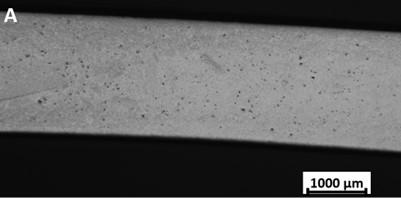
Given the similar results from the micrographic examination between Variant 4 (V4) and Variant 6 (V6), only V6 images will be shown in the present work, as more interesting from the recycle content point of view. The microstructural results and discussions will be considered representative for both alloys.
Defects and microstructure analysis. HPDC is a complex process due to the short cycle time and quick filling time involved. This combination makes HPDC a defect generating process [11], with porosity, cold flakes, cold joints and other casting defects. For this reason, it is important to include their assessment when studying new alloy, especially when it is with high recycled content. To evaluate the effect of T6 heat treatment, Fig. 1(b) shows how the porosity evolves from the as-cast (F) to the T6 state. The air entrapped naturally in the aluminum during the quick injection phase is a characteristic feature of the HPDC process and one of the major defects, as reported by Bonollo [11]. During the T6 high-temperature solution step, the air entrapped expands and can join with the surrounding air and so create bigger pores. It can be observed in Fig. 1b, where it is visually clear how T6 creates higher porosity. It is obvious how porosity is detrimental especially for ductility, as it decreases the cross section and acts as initiation point for fracture during elongation. There are two main types of pores: gas entrapment and shrinkage porosities. At this magnification level, the pores visible are due to trapped air since they show spherical shape, while the shrinkage pores can only be seen at higher magnification.
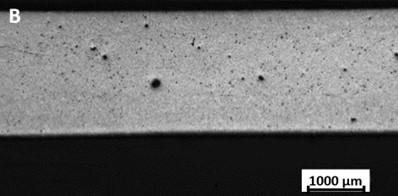
Fig. 2(a) and Fig. 2(b) show cold flakes in the as-cast and heat treated (T6) samples, respectively. Cold flakes are casting defects that form during the injection of the liquid metal in the die cavity. During the filling time of the shot sleeve, a layer of aluminum first solidifies and oxidizes in the cold chamber and when the plunger injects the molten material in the die, the solidified layer is broken in many small particles around the casting [12]. The cold flake shows a different microstructure, evidenced in the inset of Fig. 2(a) and Fig. 2(b), that creates a discontinuity from
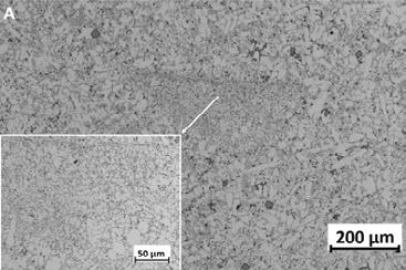
the material solidified in the die. The microstructure of the cold flake shows very fine and blocky silicon eutectics, as shown in the inset of Fig. 2(a). The cold flake is not dissolved after T6 treatment as visible in Fig. 2(b), where the defect can be observed even at low magnification. The microstructure is unchanged even if the silicon eutectics are less dispersed and show the characteristic spheroidal shape obtained during solution treatment, as reported in the inset of Fig. 2(b).
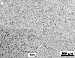
Fig.2 - Cold flake in the F (a) and T6 (b) samples, insets show magnification of the defects microstructure.
Fig. 3 shows cold joints defects found in the plate sections. It can be observed how the microstructure is different at the two sides of the line of the cold joint. This happens when, during the filling of the die, a molten metal flow that has a superficial oxide layer meets another liquid front. The microstructure of the metallurgic interface, inset of Fig. 3(a), is characterized by very fine eutectic silicon, due to the higher solidification rate of the first layer, as happened for the cold flake. The T6
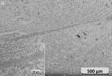
treatment homogenizes the microstructure, Fig. 3(b), losing the ultra-fine fibrous eutectics, but highlighting the microstructural discontinuity due to the interface. In fact, the air entrapped between the superficial oxide layers during the matching of the two flows expands and creates a void during the heat treatment cycle. In Fig. 3(b) it can be noted how the microstructure changes at the sides of the cold joint, as a result of the different cooling rate and the two flows.
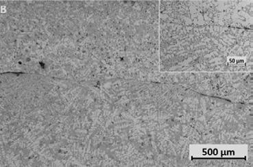
magnification of the defects microstructure.
Given the low amount of Fe and the high Mn content, as shown in Tab. 1, together with the low thickness and corresponding high cooling rate, very few β - Al5FeSi needle shape intermetallic compounds were found in the samples. Considering the chemical composition, it was expected to be much more present the α -Al15(Fe,Mn)3Si2 phase. The Fe/Mn ratio was selected for suppressing the brittle acicular β phase, while promoting the α compound, as explained also by Taylor [13]. The α -AlSiMnFe has a Chinese script-like shape as shown in Fig. 4 and they can be divided in primary and secondary, i.e., α 1- AlSiMnFe and α 2- AlSiMnFe, respectively. Primary α are coarse and solidifies in the shot sleeve or during the transfer from the cold chamber to the shot sleeve [14]. Secondary α intermetallics instead forms in the die cavity during the solidification and show a more equiaxial morphology. α 1AlSiMnFe are characterized by bigger dimension with a
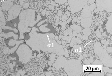
Corrosion behavior. The effect of the corrosive chamber, that simulates an accelerated salty fog environment, on the uncoated aluminum is shown in Tab. 2 in terms of weight loss. There is a clear trend difference between the F and T6 state, while only a slight variation between V4 and V6. The higher-recycle content alloy (V6) showed worse corrosive behavior, and this could be due to the higher Fe content that leads to increased Fe-rich intermetallics content that are known to have higher corrosion-susceptibility [15]. The T6 heat treatment is performed at high temperature in a non-inert atmosphere and so the hypothesis is that an oxidation passive layer grows on the surface that protects the plates from the corrosive environment. During the micrographic analysis, no evidence of this layer was
Feret diameter around 30-50 µ m, while α 2-AlSiMnFe are much finer with a Feret diameter one order of magnitude smaller, in the order of the units of µ m. This different dimension and microstructure were also found by Bosch et al. [3] with a secondary alloy having similar chemical composition. Neither the coarse nor fine α phase dissolve or change shape and dimension during T6 treatment, as can be seen by comparing Fig. 4(a) and Fig. 4(b). The strontium chemical modification led to the absence of acicular eutectic Si even in the as cast state [14], in favor of a more fibrous morphology, Fig. 4(a). After T6 and solution treatment, Fig. 4(b), the eutectic Si is transformed into spherical form with a less detrimental and brittle shape. This is the microstructural goal of an effective T6 treatment that results in an enhancement of the ductility of the component.
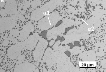
observed. The hypothesis is that the oxide layer is thinner than a micron, but it is enough to protect the aluminium substrate by an accelerated yet non extreme corrosive environment as the CASS test. Further analysis is needed to assess this different behavior, using more powerful techniques like XPS and AFM, as a scanning electron microscope (SEM) could not be powerful enough.
Tab.2 - Weight and weight losses (in grams and percentage) of the uncoated specimens after the 168h CASS test.
Mechanical properties. Bending test results correlate with the elongation at fracture as it assesses the ductility of the alloy, while hardness is related to the yield strength and ultimate tensile strength. Tab. 3 reports the bending angles and can be firstly noted the increment in ductility after T6. It is interesting to point out how also the standard deviation of the result decreases after the heat treatment, since it acts as a homogenization treatment. Very slight differences can be noted between the chemical variants in the as-cast state, while some differences can be appreciated after T6. V4
shows higher ductility than V6, even if the starting point at F state is close. The V6 has in fact more Fe as shown in Tab. 1 that leads to larger amounts of intermetallic, that even in the α form, leads to lower ductility. This slight difference in chemical composition also results in a lower standard deviation for V4 in both F and T6 states with respect to V6. The higher Fe can increase the porosity [13] in the material and the higher presence of Mn allows the formation of more α 1 intermetallic particles or sludges.
Tab.3 - Mechanical properties: bending angle with standard deviation and Brinell hardness results.
Given the numerous casting and solidification defects as the ones presented previously, bending test can give more reliable data than a traditional tensile test. The resistant section is less sensitive to the defects, since only half of it is under tension, and the skin-effect of the component, characterized by a finer microstructure, improves the mechanical performance. Tab. 3 reports the averages of the hardness measurements. The effect of the T6 decreases the hardness in both alloys, but V6 keeps a higher hardness than V4. This result agrees with the bending angle. The higher Fe content of V6 increases the hardness and tensile strength of the alloy, in agreement with Li [16]. The values obtained for both alloy variants satisfy the minimum hardness values specified by the EN 1706 standard, i.e., 80 HB for F temper and 65 HB for T6 [6].
In the present study, two variants of high-performance AlSi10MnMg aluminum alloy produced with high endof-life scrap recycle content has been characterized. Microstructural analysis, corrosion test, bending and hardness test were performed in the as cast and T6 conditions.
• The chemical composition of the two alloys differs mainly for the Fe and Cu content that derives from the higher recycle rate of V6 and the Mn content to counterbalance the Fe level.
• Despite the very high recycled content of the alloy, the detrimental element (mainly Fe, Cu and Zn) has been kept close to the reference standard EN 1706 upper limit, with V6 exceeding the Fe and Cu limit.
• The microstructure does not differ between the two
alloys, with the same casting and solidification defects and intermetallic compound. The T6 treatment has the same effect on microstructure. Few brittle β phases are formed in the alloy.
• The corrosion resistance is largely affected by the T6 treatment that is believed to have created a passivation oxide layer that greatly reduced the corrosion during CASS test. The higher Fe content of V6 leads to slightly higher corrosion susceptibility due to higher Fe intermetallics.
• The mechanical properties, measured with bending and hardness test, change after the heat treatment between the variants, while in the as cast state show similar values. The ductility of V6 after T6 decreases with respect to V4, probably as a consequence of the increased Fe content.
The results presented in this work have been partially obtained within the framework of project Horizon 2020 SALEMA, Grant Agreement no. 101003785.
The author would like to thank CRF Centro Ricerche Fiat –Stellantis, partner of the SALEMA project, for the laboratory support and the permission to publish the results.
Authors from Università di Torino acknowledge support from the Project CH4.0 under the MUR program "Dipartimenti di Eccellenza 2023-2027" (CUP: D13C22003520001).
• The mechanical properties (hardness) of the samples obtained using EoL secondary alloys satisfy the requirements fixed for the primary alloy. In perspective, the investigation of these alloys will continue for understanding the improved corrosion resistance, the effect of T5 heat treatment and the correlation of the mechanical properties to the presence of Fe intermetallics.
[1] ] Paltsev, Sergey & Chen, Y.-H. Henry & Karplus, Valerie & Kishimoto, Paul & Reilly, John & Loeschel, Andreas & von Graevenitz, Kathrine & Koesler, Simon, (2015). "Reducing CO2 from cars in the European Union: Emission standards or emission trading?", CAWM Discussion Papers 84, University of Münster, Münster Center for Economic Policy (MEP).
[2] Aluminum content in European Passenger Cars, Public Summary, 2019, Ducker Frontier.
[3] Bösch, Dominik & Pogatscher, Stefan & Hummel, Marc & Fragner, Werner & Uggowitzer, Peter & Göken, Mathias & Höppel, H.W. (2014). Secondary Al-Si-Mg High-pressure Die Casting Alloys with Enhanced Ductility. Metall and Mat Trans A. 46.
[4] Raabe, D.; Ponge, D. Making sustainable aluminum by recycling scrap: The science of “dirty” alloys. Prog. Mater. Sci. 2022, 128, 100947.
[5] https://salemaproject.eu/
[6] ISO 1706:2020, “Aluminum and aluminum alloys – Castings – Chemical composition and mechanical properties”, Int. Organ. Stand, 2020.
[7] Ceschini, Lorella & Morri, Alessandro & Toschi, Stefania & Bjurenstedt, Anton & Seifeddine, Salem. (2018). Influence of Sludge Particles on the Fatigue Behavior of Al-Si-Cu Secondary Aluminium Casting Alloys. Metals. 8. 268.
[8] Gobrecht, J. Settling-out of Fe, Mn and Cr in Al-Si casting alloys. Giesserei 1975, 62, 263–266. 15.
[9] Jorstad, J. Understanding sludge. Die Cast. Eng. 1986, 30, 30–36
[10] VDA 238-100 test specification draft: Plate bending test for metallic materials. 12/2010
[11] Bonollo, F., Gramegna, N. & Timelli, G. High-Pressure Die-Casting: Contradictions and Challenges. JOM 67, 901–908 (2015).
[12] Ahamed, Aziz & Kato, Hiroshi. (2008). Effect of cold flakes on mechanical properties of aluminium alloy die casts. International Journal of Cast Metals Research - INT J CAST METALS RES. 21. 162-167.
[13] Taylor, John. (2012). Iron-Containing Intermetallic Phases in Al-Si Based Casting Alloys. Procedia Materials Science. 1. 19–33.
[14] A.K. Dahle, K. Nogita, S.D. McDonald, C. Dinnis, L. Lu, Eutectic modification and microstructure development in Al–Si Alloys, Mater. Sci. Eng.: A 413–414 (2005) 243–248.
[15] Bjurenstedt, Anton & Casari, Daniele & Seifeddine, Salem & Mathiesen, Ragnvald & Dahle, A. (2017). In-situ study of morphology and growth of primary α-Al(FeMnCr)Si intermetallics in an Al-Si alloy. Acta Materialia. 130.
[16] Zaidao Li, Nathalie Limodin, Amina Tandjaoui, Philippe Quaegebeur, Pierre Osmond, David Balloy, Influence of Sr, Fe and Mn content and casting process on the microstructures and mechanical properties of AlSi7Cu3 alloy, Materials Science and Engineering: A, Volume 689, 2017, Pages 286-297
XIX edizione
L’Associazione Italiana di Metallurgia, per onorare la memoria del prof. Felice De Carli, ex Presidente dell’AIM, istituì nel 1968 un premio da assegnare ad un giovane ricercatore di cittadinanza italiana, che non avesse superato il 32° anno di età al momento della data di presentazione della domanda di concorso al premio e che avesse dimostrato di possedere un’adeguata maturità nel settore della ricerca metallurgica fondamentale e applicata.
L’Associazione ha deciso di bandire nuovamente il concorso per l’assegnazione del premio, consistente in una somma dell’importo di 1500 Euro e in una medaglia di ricordo recante l’effige del prof. Felice De Carli.
Per concorrere al premio occorre presentare domanda, anche a mezzo e-mail, con il testo di uno o più articoli originali del concorrente oltre che il curriculum vitae e l’elenco dei lavori già pubblicati o in corso di stampa.
La domanda va inviata, entro il 31 luglio 2024, alla Segreteria AIM, e-mail: info@aimnet.it.
La Commissione Giudicatrice, nominata dal Consiglio Direttivo AIM, a suo insindacabile giudizio, sceglierà l’Autore meritevole del premio, sia in base all’esame del lavoro inedito che dei titoli presentati.
La consegna del premio avverrà l’11 settembre 2024 a Napoli, in occasione del 40° Convegno Nazionale AIM.
Milano, 25 marzo 2024

Per informazioni e candidature: Associazione Italiana di Metallurgia Via Filippo Turati 8 - Milano t. +39 02 76021132 - t. +39 02 76397770 www.aimnet.it - info@aimnet.it
In the last decades the development of computer modeling and simulation tools have led to great advances in understanding how materials behave during Heat Treatment operations. Unfortunately, high-fidelity computational simulations can take significant time to run and require large computational capacity. Process optimization requiring many simulations at different conditions can be expensive. To mitigate these obstacles to widespread use of sophisticated computer models, Artificial Intelligence methods based on neural networks could be support the Heat Treatment processes.
KEYWORDS: MACHINE LEARNING, ARTIFICIAL INTELLIGENCE, HEAT TREATMENT
Nature has always been the source of inspirations for scientists and engineers to solve problems in various fields. Abundant instructive heat and mass transfer enhancement phenomena as well as surface related mechanisms are observed in nature, partially imitated and applied to enhance heat transfer and surface technology in engineering. Today’s manufacturing industry is witnessing a significant surge in the volume of available data. Substantial data is continuously gathered throughout the entire production process, hailing from an array of sources, including sensors, machinery, and other data collection mechanisms [1]. This data, particularly that related to product quality, holds the potential to enhance quality control and monitoring processes. In line with the European Commission's vision of "Factories of the Future," manufacturers are compelled to confront heightened competition from global rivals. One of the strategic responses to this challenge involves the integration of innovative technologies, services, and applications. The pivotal elements in this transformation lie in the extraction, management, and analysis of data. Thus, it is not only the development of Machine Learning (ML) algorithms that assumes significance but also the efficient implementation of orchestration procedures, which encompass the entire spectrum from raw process
Imre Felde
John von Neumann Faculty of Informatics, Óbuda University, Hungary
felde.imre@uni-obuda.hu
data to the deployment of a model [2]. This orchestration is often referred to as an artificial intelligence (AI) pipeline. ML plays an essential role in addressing the contemporary manufacturing hurdles that are posed by extensive and intricate data, given that raw process data lacks inherent information[3].
The common objective in research concerning Heat Treatment is to utilize deep neural networks or linear regression to create predictive models and methodologies for general steel products [23]. Carneiro et al.'s research [24], explores the prediction of quality outcomes to minimize production line bottlenecks, such as quality tests. Carneiro et al. investigates steel tubes using Artificial Neural Networks (ANN) and tree ensemble methods in the context of water-quenched steel, adopting an unsupervised approach. Their research sets itself apart from previous studies by delving into a process that incorporates data from a quenching tank, while analyzing the effects of water flow and pressure on product quality. The study of Xie et al. [25] predicts quality, focusing on yield strength and tensile strength by applying Deep Learning (DL) to raw steel parameters and process data from the reheat furnace process, rolling data, and water-cooling data at a steel plant. The cooling data encompasses measurements like average cooling rate, start and finish cooling temperature, encompassing temperatures between 200 and 900 °C. The study comprises 27 input parameters, and the deep learning model achieves an accuracy of 0.907. This research results in the deployment of the model online at an industrial site, featuring a graphical user interface to aid operators in managing hot roll process parameters through predictive analysis [25]. Hanza et al. [26] predict the total hardness of steel after continuous cooling, employing ANN. Their investigation explores whether chemical composition can be replaced as input variables by the Jominy distance. A combination of ANNs and Finite Element Method (FEM) have been used to predict Heat Transfer Coefficients (HTC) in the water quench process of large size forged steel blocks[27]. Using this method the wetting kinetics process during water quenching have been estimated on a high level of accuracy. For the explanation of hardness
alterations of a component made from the grade 18CrNi8 has been investigated by traditional physical models and data-driven ML models [27]. The prediction of hardness on cylinder heads made of 100Cr6 based on process has been performed by using AI apparatus [28]. Predictive maintenance based on massive data processing of process data has been developed for Industrial Heat Treatment operations [29], [30]. A combination of ML and the FEM have been used to predict HTC in the water quench process for large-size forged steel blocks [46]. Using this method, the wetting kinetics process during water quenching has been estimated with a high level of accuracy. The reconstruction of thermal boundary conditions including HTC occurring during immersion quenching of the ISO 9950 cylindrical probe is performed by using ANN techniques [45].
The ML has been widely applied in the deployment of Additive Manufacturing (AM) technologies. The applicability and efficiency of the ML approach in an AM process are dependent on the type of process, and the relevant design features such as material condition, process operation, part and process design, and the working environment; all these factors will be considered during the analysis [31]. Gardan and Schneider [32] conducted an optimization of the orientation, construction, design of the parts and parameters, and material. The standard techniques of AI used in rapid prototyping [33].
Within the domain of AM processes, ML is applied in two main areas: parameter optimization and process monitoring. Process parameter optimization is often a manual and time-consuming process, making it costly. Since manual parameter optimization requires the production of large numbers of samples, there is readily available data for the production of ML tools. Said tools, which make up a plurality of the research on ML for AM [34], largely take the route of optimizing key parameters for a particular quality indicator or set of indicators [35].
The porosity is the leading quality indicator in several research, Liu et al. [36] built on a “Physics-Informed Neural Network” (PINN) model rather than a conventional “setting” model. The novel PINN model was identified as being more easily generalized to other machines, although this was not tested. A key area for optimization in material
extrusion is component surface roughness [37]. Li et al. [38] built a predictive model for surface roughness based on build plate and extruder temperature, build plate and extruder vibration, and melt pool temperature. More recent works have studied the properties of the final part: Narayana et al. [39] built an ANN to predict built part height and density from laser power, scan speed, powder feed rate, and layer thickness. It was found that these parameters were all of significant importance for density whereas scan speed and feed rate had the largest effect on build height. These findings were reinforced by the model’s prediction accuracy of 99%. Xia et al.[40], used an ANN to model and predict surface roughness based on overlap ratio, welding speed, and wire feed speed with a root mean square error of 6.94%. A small training set was identified as a major limiter on the model’s accuracy [40]. While parameter optimization may help to improve process predictability, it cannot eliminate failures entirely[41]. With print failures contributing significantly to the cost of AM parts [42], process monitoring techniques able to detect build failures and defects are necessary. Various ML implementations have sought to solve this problem and fall into two categories depending on their input data type: optical and acoustic. Optical monitoring solutions are the most widely used, with the data often coming from digital, high speed, or infrared cameras [35]. In PBF processes, where the bulk of monitoring research is currently concentrated, the most common target of these computer vision tasks is the melt pool.
Quality control of AM processes has a significant role in automated production and therefore several methods have been suggested. Some of them are based on continuous camera observation and image analysis. The contour of each printed layer is compared with the desired
geometry by using metrics generated from the image of the manufactures layer.
The metrics are assumed to represent the geometrical match of these two images. The less the similarity, the higher the probability that the printing process has failed.
The procedure to obtain this layer-wise distance metrics based on the following steps:
1.) creating binary section cut images
2.) creating binary layer photos
3.) comparison of the images
In addition to, several images recorded on malfunction of AM process have been used to train the ML algorithm in order to recognize the failed production. From thermal data of the melt pool, Kwon et al. [41] trained a CNNbased program to differentiate between high, medium, and low quality builds with a failure rate of under 1.1%, allowing for potential time and cost savings. Other works have used optical data from laser melting plumes [43], [44] for similar quality classification tasks, with Zhang et al. [43], [44] finding that the best results are achieved when melt pool, plume, and spatter data are used together to classify part quality. The most recent work found a type of NN called a long–short term memory network, to be most effective in prediction, with a root mean squared error of 13.9% [43].
The Artificial Intelligence approaches supporting Heat Treatment processes have been shortly discussed in this review. These computational techniques greatly contribute to the future heat treatment technology being based on new materials, new solutions and optimized production processes.
[1] M. Elangovan, N. R. Sakthivel, S. Saravanamurugan, Binoy. B. Nair, and V. Sugumaran, “Machine Learning Approach to the Prediction of Surface Roughness Using Statistical Features of Vibration Signal Acquired in Turning,” Procedia Comput Sci, vol. 50, pp. 282–288, 2015, doi: https://doi.org/10.1016/j.procs.2015.04.047
[2] H. , & N. C. Hapke, Building machine learning pipelines. 2020. Accessed: Oct. 12, 2023. [Online]. Available: https://www.oreilly.com/ library/view/building-machine-learning/9781492053187/
[23] S. Pattanayak, S. Dey, S. Chatterjee, S. G. Chowdhury, and S. Datta, “Computational intelligence based designing of microalloyed pipeline steel,” Comput Mater Sci, vol. 104, 2015, doi: 10.1016/j.commatsci.2015.03.029.
[24] M. V. Carneiro, T. T. Salis, G. M. Almeida, and A. P. Braga, “Prediction of Mechanical Properties of Steel Tubes Using a Machine Learning Approach,” J Mater Eng Perform, vol. 30, no. 1, 2021, doi: 10.1007/s11665-020-05345-0.
[25] Q. Xie, M. Suvarna, J. Li, X. Zhu, J. Cai, and X. Wang, “Online prediction of mechanical properties of hot rolled steel plate using machine learning,” Mater Des, vol. 197, 2021, doi: 10.1016/j.matdes.2020.109201.
[26] S. S. Hanza, T. Marohnić, D. Iljkić, and R. Basan, “Artificial neural networks-based prediction of hardness of low-alloy steels using specific jominy distance,” Metals (Basel), vol. 11, no. 5, 2021, doi: 10.3390/met11050714.
[27] Y. Bouissa, D. Shahriari, H. Champliaud, and M. Jahazi, “Prediction of heat transfer coefficient during quenching of large size forged blocks using modeling and experimental validation,” Case Studies in Thermal Engineering, vol. 13, 2019, doi: 10.1016/j. csite.2018.100379.
[28] Y. Lingelbach, T. Waldenmaier, L. Hagymasi, R. Mikut, and V. Schulze, “Material matters: predicting the core hardness variance in industrialized case hardening of 18CrNi8,” Materwiss Werksttech, vol. 53, no. 5, 2022, doi: 10.1002/mawe.202100249.
[29] J. Grann, “Protecting Your Vacuum Furnace with Maintenance,” Industrial Heating, 2019.
[30] A. Goldsteinas, “The power of PDMetrics: Optimizing Operations Predictive Maintenance.,” Industrial Heating, 2021.
[31] J. Liu, Y. Zheng, Y. Ma, A. Qureshi, and R. Ahmad, “A Topology Optimization Method for Hybrid Subtractive–Additive Remanufacturing,” International Journal of Precision Engineering and Manufacturing - Green Technology, vol. 7, no. 5, 2020, doi: 10.1007/s40684-01900075-8.
[32] N. Gardan and A. Schneider, “Topological optimization of internal patterns and support in additive manufacturing,” J Manuf Syst, vol. 37, 2015, doi: 10.1016/j.jmsy.2014.07.003.
[33] S. S. Yang, N. Nasr, S. K. Ong, and A. Y. C. Nee, “Designing automotive products for remanufacturing from material selection perspective,” J Clean Prod, vol. 153, 2017, doi: 10.1016/j.jclepro.2015.08.121.
[34] M. A. Mahmood, A. I. Visan, C. Ristoscu, and I. N. Mihailescu, “Artificial neural network algorithms for 3D printing,” Materials, vol. 14, no. 1. 2021. doi: 10.3390/ma14010163.
[35] C. Wang, X. P. Tan, S. B. Tor, and C. S. Lim, “Machine learning in additive manufacturing: State-of-the-art and perspectives,” Additive Manufacturing, vol. 36. 2020. doi: 10.1016/j.addma.2020.101538.
[36] R. Liu, S. Liu, and X. Zhang, “A physics-informed machine learning model for porosity analysis in laser powder bed fusion additive manufacturing,” International Journal of Advanced Manufacturing Technology, vol. 113, no. 7–8, 2021, doi: 10.1007/s00170-02106640-3.
[37] I. Gibson, D. W. Rosen, and B. Stucker, Additive manufacturing technologies: Rapid prototyping to direct digital manufacturing. 2010. doi: 10.1007/978-1-4419-1120-9.
[38] Z. Li, Z. Zhang, J. Shi, and D. Wu, “Prediction of surface roughness in extrusion-based additive manufacturing with machine learning,” Robot Comput Integr Manuf, vol. 57, 2019, doi: 10.1016/j.rcim.2019.01.004.
[39] P. L. Narayana et al., “Optimization of process parameters for direct energy deposited Ti-6Al-4V alloy using neural networks,” International Journal of Advanced Manufacturing Technology, vol. 114, no. 11–12, 2021, doi: 10.1007/s00170-021-07115-1.
[40] C. Xia, Z. Pan, J. Polden, H. Li, Y. Xu, and S. Chen, “Modelling and prediction of surface roughness in wire arc additive manufacturing using machine learning,” J Intell Manuf, vol. 33, no. 5, 2022, doi: 10.1007/s10845-020-01725-4.
[41] O. Kwon et al., “A deep neural network for classification of melt-pool images in metal additive manufacturing,” J Intell Manuf, vol. 31, no. 2, 2020, doi: 10.1007/s10845-018-1451-6.
[42] M. Baumers, P. Dickens, C. Tuck, and R. Hague, “The cost of additive manufacturing: Machine productivity, economies of scale and technology-push,” Technol Forecast Soc Change, vol. 102, 2016, doi: 10.1016/j.techfore.2015.02.015.
[43] Z. Zhang, Z. Liu, and D. Wu, “Prediction of melt pool temperature in directed energy deposition using machine learning,” Addit Manuf, vol. 37, 2021, doi: 10.1016/j.addma.2020.101692.
[44] Y. Zhang, G. S. Hong, D. Ye, K. Zhu, and J. Y. H. Fuh, “Extraction and evaluation of melt pool, plume and spatter information for powder-bed fusion AM process monitoring,” Mater Des, vol. 156, 2018, doi: 10.1016/j.matdes.2018.07.002.
[45] S. Szénási, I. Felde, G. Nagy and A. Deus, "Estimating the Heat Transfer Coefficient Using Universal Function Approximator Neural Network," 2018 IEEE 12th International Symposium on Applied Computational Intelligence and Informatics (SACI), Timisoara, Romania, 2018, pp. 000401-000404, doi: 10.1109/SACI.2018.8440928.
[46] ASM Handbook, Volume 4F: Quenchants and Quenching Technology (Editor: George E. Totten, Rosa Simencio Otero, Xinmin Luo, Lauralice C.F. Canale), ISBN: 978-1-62708-448-2
DIGITAL COMMUNICATION
PREVENTIVE MAINTENANCE
ENERGY METER
SW CONFIGURATION
SCCR UL 508 100KA
CERTIFIED
!
TOTAL AND PARTIAL LOAD FAILURE ALARM
PROCESS VALUES MONITORING
• Current rating from 40A to 600A
• Voltage 480Vac, 600Vac e 690Vac
• Single, dual and three phase
• Linear resistance, MoSi2, Sic, SWIR, Graphite, Transformers
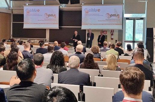
Opening Ceremony of the 4th Mediterranean Conference on Heat Treatment and Surface Engineering (MCHTSE 2024) and the 5th International Conference on Thermal Process Modeling and Simulation (TPMS-5).
Closing Remarks


The Aichelin Young Speaker Award was awarded to Alessandra Palombi from Università di Roma Tor Vergata for the paper «Low temperature plasma assisted carburizing of 3D-printed 316 L stainless steel» presented at the 4th Mediterranean Conference on Heat Treatment and Surface Engineering and 5th International Conference on Thermal Process Modeling and Simulation held in Lecce, Italy, in April 2024.
The prize was awarded for the best presentation, considering the quality of the presentation, clarity of exposition and the candidate's ability to answer questions. Eighteen participants took part in the competition, presenting very interesting and high-quality works. Congratulations to Dr. Alessandra Palombi and thanks to Aichelin for supporting IFHTSE, the International Federation for Heat Treatments and Surface Engineering, in its commitment to young researchers.

CONVEGNI
IFM 2024 - INTERNATIONAL FORGEMASTERS MEETING – Milano, 27-30 maggio 2024
ESOMAT 2024 - 12th European Symposium on Martensitic Transformations – Lecco, 26-30 agosto 2024
40° CONVEGNO NAZIONALE AIM – Napoli, 11-13 settembre 2024
ECIC 2024 - 9TH EUROPEAN COKE AND IRONMAKING CONGRESS – Bardolino, 16-18 ottobre 2024
International Meeting on CIRCULAR METALLURGY - Raw Materials, By-products & Recycling – Bergamo, 2829 novembre 2024
CORSI E GIORNATE DI STUDIO
Corso modulare TRATTAMENTI TERMICI – Milano, 8-9-15-16 maggio, Avigliana TO c/o Motivexlab, 22-23 maggio, Campogalliano MO c/o Tec Eurolab, 5-6 giugno 2024
Corso itinerante METALLURGIA FUORI FORNO – 22-23 maggio, 12-13 giugno 2024
Giornata di Studio ESG: sostenibilità, carbon footprint, energia green per il settore trattamenti termici – Brescia c/o Blu Brixia Hotel e via zoom - 6 giugno 2024
Giornata di Studio SBM – Smart Bean Manufacturing: NUOVO LAMINATOIO PER TRAVI – San Zeno sul Naviglio c/o Duferco, 7 giugno 2024
Corso PROVE MECCANICHE - Miano, 12-13-19-20 giugno 2024
Giornata di Studio FUTURO SOSTENIBILE E COMPETITIVO DELLA METALLURGIA DELLE POLVERI – Maerne c/o Pometon, 13 giugno 2024
Corso MICROSCOPIA ELETTRONICA IN SCANSIONE – Milano, 18-19 giugno 2024
Corso RIVESTIMENTI – II MODULO: RIVESTIMENTI SPESSI – Milano, 19-20 giugno 2024 METALLURGY SUMMER SCHOOL ON ADDITIVE METALLURGY – Bertinoro, 30 giugno - 1,2,3 luglio 2024
Corso METALLURGIA PER NON METALLURGISTI – Milano, 15-16-22-23-29-30 ottobre 2024
Giornata di Studio MICROSCOPIA ELETTRONICA APPLICATA ALLA FAILURE ANALYSIS – Milano, 6 novembre 2024
Giornata di Studio RAGGI X – Milano, 3 dicembre 2024
Giornata di Studio NUOVI SVILUPPI ADDITIVE MANUFACTURING PER BIOMEDICALE – Milano c/o PoliMi, 5 dicembre 2024
FaReTra (Fair Remote Training) - FORMAZIONE E AGGIORNAMENTO A DISTANZA
Modalità Asincrona (registrazioni)
Webinar NORMATIVA NEL CAMPO DEI TRATTAMENTI TERMICI
Giornata di Studio STATO DI SERVIZIO DEGLI IMPIANTI, CON PARTICOLARE ATTENZIONE ALLA METALLURGIA E AGLI ESAMI UTILIZZATIz
Giornata di Studio LA NORMATIVA: GLI ACCIAI E I TRATTAMENTI TERMICI NELL'INDUSTRIA AUTOMOTIVE
Corso PROVE NON DISTRUTTIVE
Giornata di Studio TRATTAMENTI SUPERFICIALI DELL’ALLUMINIO A SCOPO DECORATIVO E PROTETTIVO
Corso Modulare METALLOGRAFIA – I MODULO, II MODULO “METALLI NON FERROSI”
Corso modulare FONDERIA PER NON FONDITORI
Corso DIFETTOLOGIA NEI GETTI PRESSOCOLATI: METALLIZZAZIONI
Corso ADDITIVE METALLURGY
Corso METALLURGIA PER NON METALLURGISTI
Giornata di Studio PRESSOCOLATA DELLE LEGHE DI ZINCO
Giornata di Studio LA SFIDA DELLA NEUTRALITÀ CARBONICA
Corso modulare TRATTAMENTI TERMICI
Corso modulare I REFRATTARI SIDERURGICI E LE LORO APPLICAZIONI
Corso GLI ACCIAI INOSSIDABILI 11ª edizione
Corso FAILURE ANALYSIS 11a edizione
L’elenco completo delle iniziative è disponibile sul sito: www.aimnet.it
www.aimnet.it
CT METALLI LEGGERI (ML) (riunione del 15 dicembre 2023)
Manifestazioni in corso di organizzazione
• Il corso “Igiene delle leghe da fonderia”, organizzato in collaborazione con il CT Pressocolata e coordinato da Muneratti, si svolgerà a Rovigo presso TMB il 17-18 aprile. Timelli precisa che la capienza della sala è limitata a 60 persone, e le iscrizioni saranno chiuse se si raggiugerà quel numero. Si pensa che la visita agli impianti TMB possa invogliare molti utenti a partecipare. Il programma è definito e completo.
Iniziative future
• GdS “Ecosostenibilità e emissioni di CO2” (coordinatori Sinagra e Morri): Sinagra spiega che l’argomento è molto sentito in ambito industriale e sarebbe interessante coinvolgere più settori (pressocolata, estrusione, produzione leghe, ecc.). Bisognerebbe introdurre i rudimenti di LCA invitando qualcuno per discutere su come si esegue una valutazione di LCA seguendo le normative. Bassani comunica che il centro metallurgia delle polveri aveva discusso un argomento simile, poi non portato avanti: forse si può fare una giornata trasversale coinvolgendo altri centri studio. I punti chiave potrebbero essere il “come fare un LCA efficace” e “quali siano le finalità”, e poi portare testimonianze da diversi settori: fonderia, laminazione, metallurgia delle polveri... Bassani scriverà una e-mail per spiegare il progetto e inoltrarla agli altri centri studio.
• Manifestazione su Magnesio: si torna a discutere sulla possibile organizzazione di un evento sul magnesio (coordinatore Spaccasassi). Secondo Timelli anche questa GdS dovrebbe essere trasversale, passando dal settore biomedico all’automotive: anche solo cogliere informazioni sul mercato attuale è di interesse, visto che l’ultima giornata sulle leghe del Mg risale al 2008. Spaccasassi ha contattato una nota raffineria che produce leghe di Mg per il settore aeronautico per un contributo tecnico.
(riunione del 26 marzo 2024)
Manifestazioni in corso di organizzazione
• GdS “Futuro sostenibile e competitivo della metallurgia delle polveri”: il coordinatore Molinari presenta la bozza di programma con titoli e possibili relatori da coinvolgere. I relatori presenti confermano la disponibilità e il programma viene approvato dal comitato, mentre saranno contattati i relatori non presenti. Rampin conferma la disponibilità da parte di Pometon di ospitare l’evento, ricordando che eventualmente ci sarà il limite sul numero massimo di partecipanti. Viene fissata la data del 13 giugno 2024. La locandina dovrà essere pronta entro metà aprile in modo da avere sufficiente tempo per la promozione.
Iniziative future
• GdS “Nuovi sviluppi dell’Additive Manufacturing per applicazione biomedicale”: Casati e Biffi hanno lavorato ad una prima idea di programma individuando già le aziende e gli enti da coinvolgere. La manifestazione si terrà a Lecco nel giugno 2024.
(riunione del 04 aprile 2024)
Iniziative future
• XXXVII Congresso di fonderia – sessioni tecniche: il presidente Caironi chiede di coinvolgere i colleghi per la presentazione di memorie. Assofond ha provveduto ad inviare comunicazione ufficiale per la tenuta delle sessioni tecniche del congresso con relativa richiesta di presentazione delle memorie e dei premi studio. Le memorie saranno esposte esclusivamente in modalità web, ma Assofond sta valutando la possibilità di aggiungere una giornata in presenza con una parte congressuale con qualche memoria di alto livello su un unico tema ed una parte conviviale, in cui ad esempio si potrebbe aggiungere una visita del luogo in cui sarà tenuta o presso una fonderia.
• Corso “Fonderia per non fonditori” – moduli successivi (ghisa, acciaio e leghe non ferrose). Il Comitato ha valutato che questo corso
debba essere tenuto con frequenza biennale, negli anni in cui non viene tenuto il congresso Assofond, inserendo eventuali moduli specifici per le diverse tipologie di leghe, indirizzati agli addetti di fonderia. Si è deciso di programmare il prossimo corso nel 2025. Si è valutata la possibilità di inserire alcune serie di esempi di realizzazioni di particolari realizzati per fusione e di predisporre, all’interno del corso, un filmato che mostri le varie fasi del processo di fonderia.
• GdS “Refrattari utilizzati in fonderia” e pillole di fonderia “Il processo di scorifica delle leghe ferrose”: il presidente legge le bozze dei programmi da lui prodotti sulla base dei corsi tenuti dal Professor Carlo Mapelli, il quale, insieme a Gruttadaria, si è reso disponibili a sviluppare per la prossima riunione tali bozze con l’indicazione di eventuali docenti.
• Pillole di fonderia su “Conduzione dei forni ad induzione”: viene valutata l’eventualità di sviluppare questo corso semplicemente come singolo modulo all’interno dei corsi discussi nel punto precedente o di tenere in sospeso il suo sviluppo che potrà essere ripreso successivamente.
Norme pubblicate e progetti in inchiesta (aggiornamento al 29 marzo 2024)
Norme UNSIDER pubblicate da UNI nel mese di marzo 2024
UNI EN 10270-1:2024
Filo di acciaio per molle meccanicheParte 1: Filo di acciaio non legato per molle trafilato a freddo e patentato
Norme UNSIDER ritirate con sostituzione da UNI nel mese di marzo 2024
UNI EN 10270-1:2017
Filo di acciaio per molle meccaniche -
Parte 1: Filo di acciaio non legato per molle trafilato a freddo e patentato
Norme UNSIDER pubblicate da CEN e ISO nel mese di marzo 2024
EN ISO 13702:2024
Oil and gas industries - Control and mitigation of fires and explosions on offshore production installations - Requirements and guidelines (ISO 13702:2024)
EN 17878-1:2024
District heating pipes - Factory made flexible pipe systems with a lower temperature profile - Part 1: Classification, general requirements and test methods
EN 17878-3:2024
District heating pipes - Factory made flexible pipe systems with a lower temperature profile - Part 3: Requirements and test methods for non bonded systems with plastic service pipes
EN 17878-2:2024
District heating pipes - Factory made flexible pipe systems with a lower temperature profile - Part 2: Requirements and test methods for bonded systems with plastic service pipes
EN 10348:2024
Steel for the reinforcement of concreteGalvanized reinforcing steel products
EN 10251:2024
Magnetic materials - Methods of determination of the geometrical characteristics of electrical steel sheet and strip
ISO 16132:2024
Ductile iron pipes and fittings — Seal coats for cement mortar linings
ISO 13702:2024
Oil and gas industries — Control and mitigation of fires and explosions on offshore production installations — Requirements and guidelines
ISO 8371:2024
Iron ores for blast furnace feedstocks — Determination of the decrepitation index
ISO 4993:2024
Steel and iron castings — Radiographic testing
Progetti UNSIDER messi allo studio dal CEN (Stage 10.99) – aprile 2024
prCEN ISO/TS 6892-5
Metallic materials ” Tensile testing” Part 5: Specification for testing miniaturised test pieces
Progetti UNSIDER in inchiesta prEN e ISO/DIS – aprile 2024
prEN – progetti di norma europei
prEN ISO19901-5
Petroleum and natural gas industries - Specific requirements for offshore structures - Part 3: Topsides structure (ISO/DIS 19901-3:2022)
prEN ISO 4937
Steel and iron - Determination of chromium content - Potentiometric or visual titration method (ISO/DIS 4937:2024)
prEN 10379
Steel sheet piles - Test methods
ISO/DIS – progetti di norma internazionali
ISO/DIS 12747
Oil and gas industries including lower carbon energy — Pipeline transportation systems — Recommended practice for pipeline life extension
ISO/DIS 7692
Ferrotitanium — Determination of titanium content — Titrimetric method
ISO/DIS 6331
Chromium ores and concentrates — Determination of chromium content — Titrimetric method
ISO/DIS 4937
Steel and iron — Determination of chromium content — Potentiometric or visual titration method
Progetti UNSIDER al voto FprEN e ISO/FDIS – aprile 2024
FprEN – progetti di norma europei
FprEN ISO 10113
Metallic materials - Sheet and stripDetermination of plastic strain ratio (ISO/ FDIS 10113:2019)
ISO/FDIS – progetti di norma internazionali
ISO/FDIS 15544
Oil and gas industries — Offshore production installations — Requirements and guidelines for emergency response
ISO 13623:2017/FDAmd 1
Petroleum and natural gas industries — Pipeline transportation systems — Amendment 1: Complementary requirements for the transportation of fluids containing carbon dioxide or hydrogen
ISO/FDIS 14577-5
Hot-rolled longitudinally profiled steel plate
ISO/FDIS 6398-1
Oil and gas industries including lower carbon energy — Submersible linear motor systems for artificial lift — Part 1: Submersible linear motor
6-9 OCTOBER
IRONMAKING

STEELMAKING
ROLLING OF FLAT AND LONG PRODUCTS, FORGING
STEEL MATERIALS AND THEIR APPLICATION, ADDITIVE MANUFACTURING, SURFACE TECHNOLOGIES
HYDROGEN-BASED STEELMAKING, CO2-MITIGATION, TRANSFORMATION /ENVIRONMENT /ENERGY
DIGITAL TRANSFORMATION
Organised by