As we prepare to embark on the 2024–2025 training season, I wanted to take a moment to introduce our exciting new watercraft curriculum.
Back in 2020, Yamaha took a significant step forward by developing a curriculum specifically designed to certify Watercraft Master Technicians. This initiative led to the creation of several new courses, starting with the foundational Electrical-I course. This course, which was first introduced for the 2022–2023 training season, covers essential skills such as the theory behind Ohm’s Law and Watts Law, building electrical circuits, and, most importantly, introducing voltage drop testing.
Building on this foundation, the Watercraft Powertrain course was developed next. Launched during the 2023–2024 training season, this course teaches students how to use precision measuring tools for Yamaha service procedures and guides them through the dismantling and reassembly of various watercraft engines.
For the upcoming 2024–2025 training season, we are thrilled to announce the addition of two new courses: Electrical-II and Electronic Fuel Injection (EFI).
The Electrical-II course will expand upon the concepts introduced in the Electrical-I course, delving deeper into starting, charging, and ignition systems, as well as wiring diagram usage and new diagnostic techniques. Additionally, students will be introduced to CAN-bus communication circuits, which will be essential for future courses.
The EFI course is an in-depth exploration of the inputs and outputs necessary for controlling fuel injection, including the functioning of all EFI sensors and the role of the ECU. This course also covers the additional components used in the 4-Star emissions engine.
These four courses form the foundation of our watercraft curriculum and will be essential for students aiming to become well-rounded technicians. Looking ahead, these courses will also prepare students for the final two courses in our curriculum: Advanced Sport Boat Technology and Advanced WaveRunner Technology, which will be offered in future training seasons
The Advanced Sport Boat course covers all systems unique to Sport Boats, and passing this course will be a prerequisite for taking the Boat Master Technician test. Similarly, the Advanced WaveRunner course focuses on the systems and components unique to WaveRunners, and passing this course will be required to take the WaveRunner Master Technician test.
We are excited to offer these courses in the 2024–2025 training season and look forward to supporting your journey toward becoming a certified Watercraft Master Technician.
Thank You!
Shaun Forgacs Instructional Designer Yamaha Marine University Training
Please scan the QR Code® to the right to participate in a brief survey that will help establish a reference document that technicians will be able to refer to and locate specific articles within On Board as needed.
KNOW? DID YOU
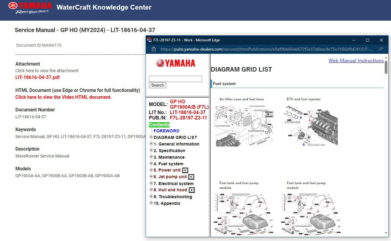
HTML Interactive Manuals
Did you know that HTML interactive manuals have been added to select Service and Owner’s Manual landing pages in the YMBS and YDS Knowledge Centers? These manuals provide wonderful tips, diagrams, and videos to help you complete daily tasks in a timely manner. To use this new useful resource, simply look for the HTML link listed below the manual’s PDF file.
REMOVING A STUCK COLLAR AND SPACER ABOVE THE ANTI-KNOCK WASHERS
By David Mitas, District Service Manager and YMU™ Instructor
As District Service Managers, we visit a lot of dealers and, along the way, meet a lot of great people. I remember talking with a resourceful technician a few years ago about anti-knock washer removal. Located above the water pump impeller, these washers, two plain and one wave washer (sandwiched between the plain washers), are used to preload the driveshaft, pulling up on it to seat the upper driveshaft thrust bearing.
The problem? To get to them you must first remove the stainless steel collar and plastic spacer above them on the driveshaft. And these can be stuck firmly in place, often making the process surprisingly difficult. We offered some useful tips and tricks way back in the March 2011 issue of On Board (available in the Knowledge Center on YMBS). If you just try to pry up on the collar, it tries to lift the plastic spacer with it. I’ve seen a lot of techs resort to extreme measures here, such as cutting the collar off with a chisel or cutting wheel or melting the plastic spacer with a torch.
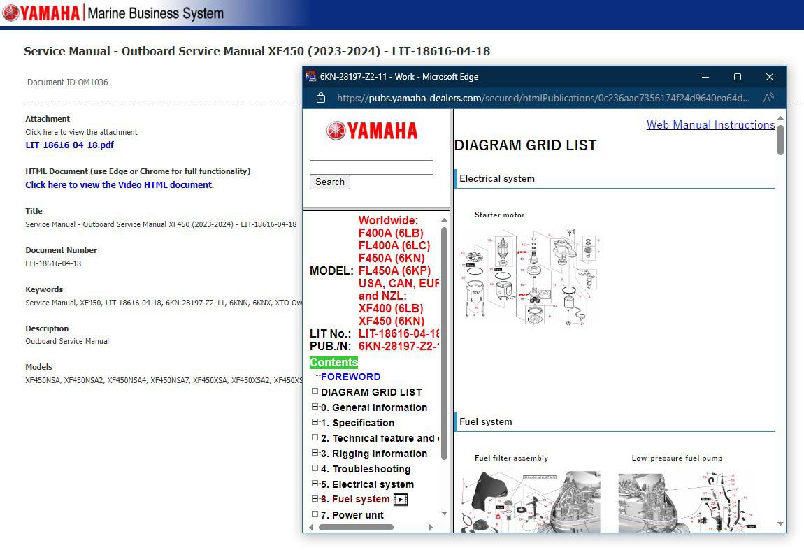
During our conversation that day, this particular tech shared a simple and innovative way to remove them. He made a tool from an old water pump base plate (hundreds of which you have probably thrown out while replacing water pump kits). He cut the old base plate in half, followed by some minor grinding and filing.
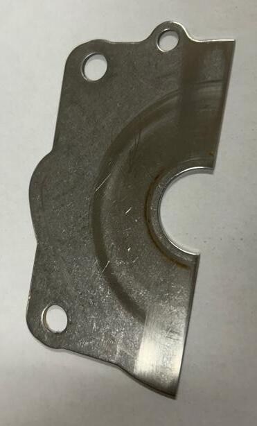
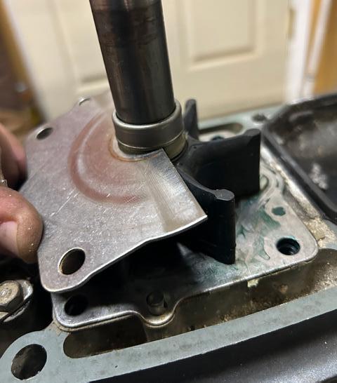
He showed me how it works by sliding the tool between the plastic and stainless collar, and then, with a simple up-and-down movement, separating the stainless collar from the plastic spacer—without damage—so you can reuse them.
With the assembly apart, you can more easily remove the pieces and install the new parts. Don’t forget to pull up on the driveshaft while tapping the stainless
collar back in place, as noted in “Removing Driveshaft Anti-Knock Spring Retainer” in the March 2011 issue of On Board. Otherwise, you will likely get unhappy customers who bring their boat back in saying, “My engine has a knocking noise in gear at idle now after you guys replaced the water pump,” (a noise that goes away when throttle is advanced a few hundred rpm).
There is also an aftermarket drive shaft collar adapter tool for Yamaha outboards that you can find via a Google® search that will remove the collar; cost is around $25.
P.S. If the tech I got this modified-base-plate tip from reads this, drop us a line and we will send some swag your way!
Editor’s Note: Additionally, we want to thank Chris Hogan, owner of Hogan Marine, LLC for submitting this topic as our Tech Tip for October!
SUBMIT YOUR TIP TODAY!
If your tip is accepted for publishing, you will receive a coupon for a free Yamaha hat from Yamaha’s online technician and dealer store! As a reminder, Tech Tip Corner is designed to let technicians share their knowledge, tips, and tricks with their fellow Yamaha marine technicians. If you have a tip you would like to share and have published, please email, Marine_On_Board@yamaha-motor.com or scan the QR Code. NOTE: Yamaha cannot validate each submitted tip for time savings, effectiveness, or suitability for every service technician’s experience and skill level. Evaluate tips carefully before using them.
WHAT’S NEW IN THE KNOWLEDGE CENTERS!
The Knowledge Centers are packed full of information that you can refer to while completing daily tasks. Simply use the keyword search to track down what you need. You can also browse through each category tab on the sidebar to see the different types of information provided. Here are some additions to the Knowledge Centers that will hopefully continue to help you.
YMBS
OWNER’S AND SERVICE MANUALS
The following manuals have been uploaded to the Knowledge Center. To better service your customers’ outboards, you can search for the applicable manuals by inputting the LIT number or the model of the outboard motor into the search bar.
Owner’s Manual – F150C/ LF150C – LIT-18626-14-94
Service Manual – Outboard Service Manual (MFG 2019-2024) F20B – LIT-18616-03-90
Service Manual – Outboard Service Manual (MFG 2020-2024) VF115A – LIT-18616-04-02
Service Manual – Outboard Service Manual XF450 (2023-2024) – LIT-18616-04-18
RIGGING GUIDES
Rigging Guides provide you with step-by-step instructions on how to efficiently set up certain accessories on an outboard motor, such as the Helm Master EX as well as other components.
2024 Helm Master EX – 6X9 Digital Electronic ControlRigging Guide – LIT-18616-04-54
CATALOGS
From rigging components to accessories and apparel, Yamaha’s Marine Rigging and Parts (MRP) catalog has it all. Please check out our brand new 2024 MRP catalog, already sectioned for your convenience!
INFO EXCHANGES
Info Exchanges keep you updated with the latest technical information pertaining to Rigging and Parts, Service Procedures, YDIS, and Warranty!
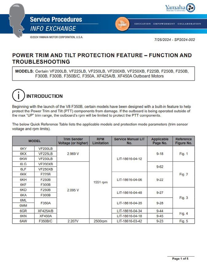
Power Trim and Tilt Protection Feature – Function and Troubleshooting – SP2024-002
New Trim Cylinder End Cap Removal and Installation Tool – SP2024-003
2M Outboard Oil Return – SP2024-004
YDS
If your dealership works with WaterCraft products, here are a few tips to help you quickly find the information you need. Like the YMBS Knowledge Center, simply use the keyword search to track down what you need. You can also browse through each category tab on the sidebar to see the different types of information provided.
OWNER’S AND SERVICE MANUALS
The following manuals have recently been uploaded to the Knowledge Center. To better service your customers’ watercraft, you can search for the applicable manuals by inputting the LIT number in the search bar or selecting the model of the watercraft from the drop-down menu.
Owner’s/ Operator’s Manual – GP SVHO – LIT-18626-15-22
Owner’s/ Operator’s Manual – GP HO – LIT-18626-15-23
NOTE: RiDE® Model and Supplementary Service Manuals contain updated service information for certain WaveRunner® models. Make sure to also refer to these manuals if you are unable to locate specific information in the main applicable Service Manual.
WHAT’S NEW IN THE KNOWLEDGE CENTERS!
INFO EXCHANGES
Info Exchanges keep you updated with the latest technical information pertaining to Parts and Accessories, Service Procedures, YDIS, and Warranty!
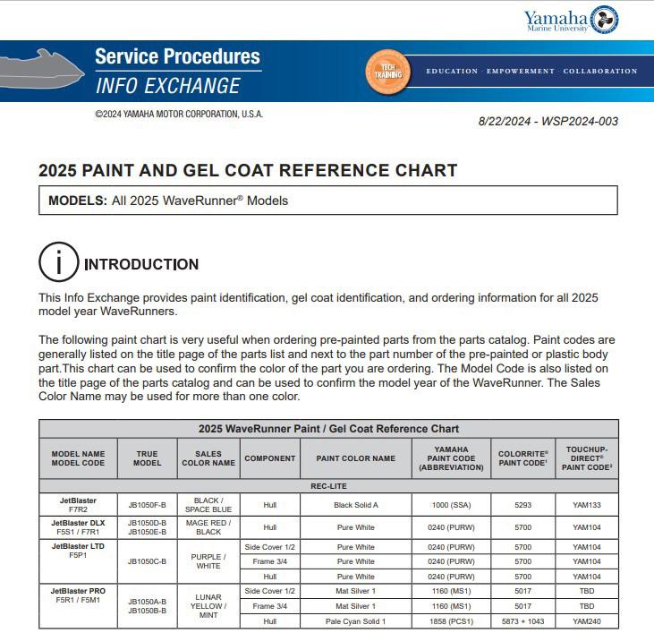
2025 Paint and Gel Coat Reference Chart – WSP2024-003
2025 Gel Coat and Touch-Up Paint Reference Chart –BSP2024-003
Audio Component Warranty Instructions and Troubleshooting Assistance Contact Information –BSP2024-004
TECHNICAL VIDEOS
Technical videos provide step-by-step instructions on topics such as how to update systems, accessory installation, and regular maintenance. Check out the videos by scanning the QR Codes below to learn more or even refresh your memory about how to complete certain procedures.
Accessory Installation Video – 195 AR Mooring Cover Installation Video
Remember that the YMBS and YDS Knowledge Centers can provide you with copious amounts of information that will make it easier to complete your daily tasks. If you need reference material when working on a customer’s outboard, be sure to check the Knowledge Center for whatever you might need.
220 FSH Boat – Peel & Stick Transom Mat Installation
220 FSH Boat – Snap-In Deck Mat Installation Video
YMBS DEALER DASHBOARD!
The Dealer Dashboard aims to assist dealerships in improving their business operations to increase customer satisfaction by enhancing the ability to view maintenance data, increasing business efficiency through preventative maintenance requests, utilizing maintenance information for dealer support, and receiving remote notifications of usage information and trigger alerts generated on customers’ boats.
There are five main aspects of the components that make up the “Dealer Dashboard” functionality:
IMPORTANT: These five features are only available on Digital Electronic Control (DEC) outboard motors. These features are not available on Mechanical Remote Control outboard models.
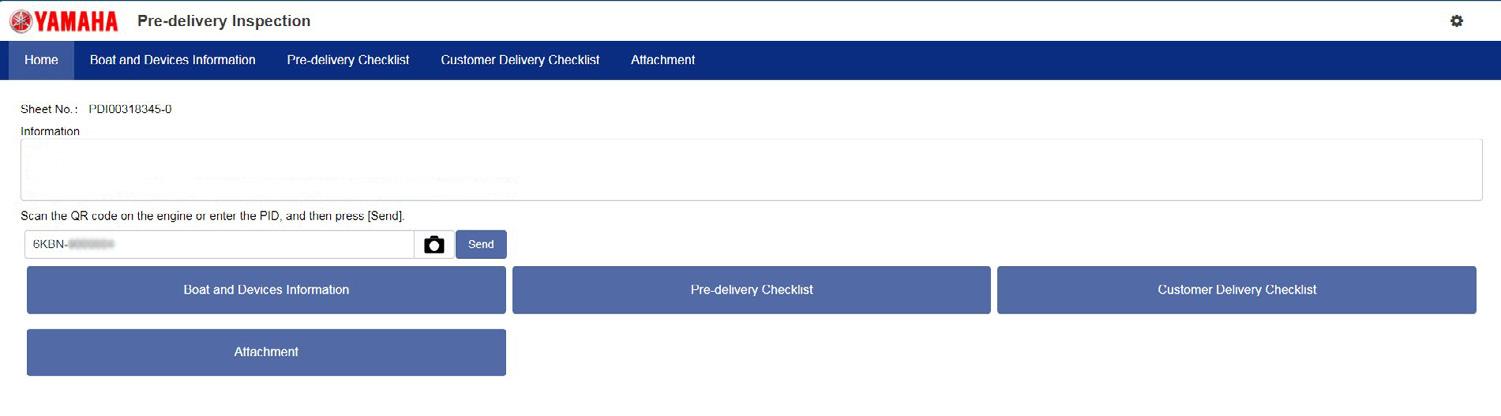
1. Digital Pre-Delivery Inspection (PDI): A digital form of a traditional PDI checklist that can be created online and electronically signed by the dealership and customer.
2. Periodic Inspection: Allows dealers to log their results and notes when they perform regular inspections on a customer’s boat through YMBS.
3. Repair and Maintenance: A way for dealers to add or review repair and maintenance information on YMBS.
YMBS DEALER DASHBOARD!
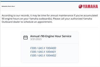
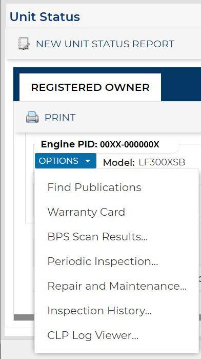
4. Inspection History: A feature that displays the history of when the engine has been serviced.
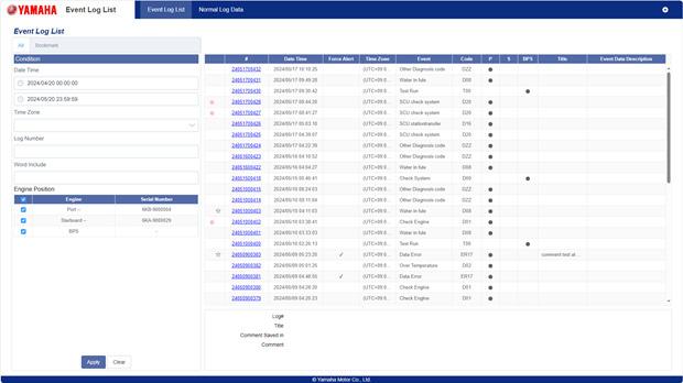
5. Command Link Plus® Viewer: A feature that displays triggering events and daily usage data. NOTE: This feature is available on Digital Electronic Control (DEC) outboard motors also equipped with the Siren® 3 Pro system.
DEALER DASHBOARD STORAGE
The Dealer Dashboard communicates daily with a Yamaha-factory-based storage server* to access inspection, usage, and maintenance information on customers’ boats. This is how the Dealer Dashboard storage works:
1. First, the dealer must create a Digital PDI and perform a BPS scan to enter the boat information.
2. At that point, a master file is created for the boat and saved on Yamaha’s cloud-based server. Information is again updated after warranty registration.
3. If a boat is using the Siren 3 Pro system, the Siren Marine management system sends alerts to the boat’s master server file for dealerships to monitor remotely. However, this is not required other functions of the Dealer Dashboard storage to work.
*If customers have questions about data collection, storage, and use, please direct them to Yamaha’s Privacy Policy, available at https://yamaha-motor.com/privacy-policy
SETTING A PREFERRED DEALER
For a dealership to receive notifications about a boat, the dealership needs to be set as a preferred dealer.
There are two ways to do this:
Option 1: The dealership sets the preferred dealer during the warranty registration.
Option 2: The customer chooses their preferred dealer from their Siren Marine app on their phone. The data will then transfer from the Siren 3 Pro on the boat each night to the server for dealerships to retrieve.
LEARN MORE ABOUT THE DEALER DASHBOARD
To view what all the Dealer Dashboard has to offer, refer to the Dealer Dashboard Quick Guide booklet located on the YMBS Knowledge Center.
Yamaha Marine University™ has also created an E-learning module to train dealers on how to access and navigate the new Dealer Dashboard. By the end of this module, you will:
• Understand the purpose and functionality of the Dealer Dashboard, which assists dealers with registration and event management.
• Review the digital pre-delivery inspection process to ensure product readiness.
• Learn how to locate trigger and daily event log information efficiently.
• Master the process of updating repair and maintenance reports.
This comprehensive module is designed to equip you with the knowledge and skills necessary to optimize dealer operations and enhance service efficiency.
HOW TO FIND THE TRAINING
1. Log on to train.yamahalearning.com or scan the QR Code below.
2. Type Dealer Dashboard in the search bar.
3. Click the course thumbnail.
4. Click Launch.
Take Care of Tools and They Will Take Care of You!
By John “Wilkie” Wilkinson, Marine Technical Support Manager
You rely on tools to do your job and, if you are like most technicians, you keep them clean, serviced, and maintained.
Remember the engine that had water in the cylinders, and you used your compression tester? Did you clean the Schrader® valve and clear the lines? Or the boat that had water in the fuel that you found after you had connected your vacuum and fuel pressure gauge?
One of my favorite phrases is, “Invest in your tools and you invest in your future.”
What about dealership tools? Are you taking care of them like they were your own? In the hustle of daily operations, it is easy to overlook the condition of shop equipment. However, you rely on them to get a task done, and if you are not maintaining them, who is?
One of our District Service Managers, Jesse Dayton, was recently helping one of his dealers diagnose a highspeed-running issue. He recommended the dealer use a shop fuel tank as the results for the fuel test were unchanged. It turns out that the shop tank had a small, older fuel line, which partially clogged the primer bulb and obstructed pick up.
It’s easy to take it for granted when the shop tank has fresh fuel, the shop is equipped to handle a large horsepower engine, the battery jump pack is charged, the air compressor oil is clean, the tank and filters are drained, and the Yamaha Diagnostic System (YDIS) kit is up to date with all necessary hardware. But what happens to your day when tools and equipment are not in the condition or place where they should be? Imagine how much better it would be to not go hunting for a tool only to find it broken.
Although you might not have an opportunity to maintain shop equipment every day, it is important to at least identify the need for maintenance. A clipboard or checklist of tasks can be helpful for when you do have the opportunity.
It’s important for you to be familiar with all of your resources, tools, and shop equipment. The more you learn and know about how to use and depend on them, the more efficient you will be in completing your daily tasks.
Finally, I want to remind you of your most important tool of all, yourself.
After almost 50 years in Marine Service, the only reason I can still hear and see is because of wearing hearing and eye protection. I should have stopped “jumping” out of boats sooner and asked for help when lifting heavy parts. As far as the exposure to the sun and chemicals: rubber gloves, sunglasses, sunscreen, and respirators should always be on your mind. To shop for appropriate gear to combat the elements, be sure to check out our Yamaha Marine Technician and Dealer Store by clicking the link or scanning the QR Code.
BACK TO BASICS: Best Practices
By Fred Huff, Factory Technical Specialist
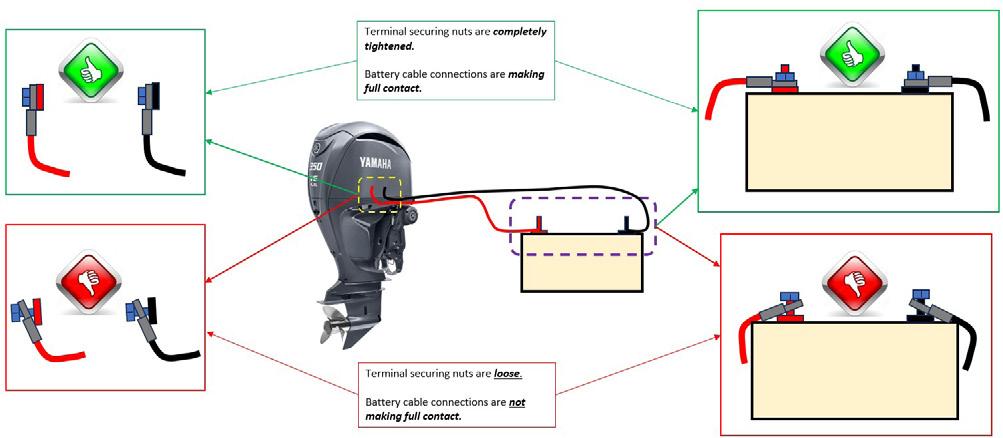
Given the robust electronic features of today’s outboard motors, it is important to go back to basics and ensure that your dealership is using the best practices for maintaining and connecting the outboards you service.
For example, when attaching a battery to the engine, always make sure that the battery connections are completely secured. If there isn’t full contact in the connections, there can be excessive fluctuations in the power supplied to the electrical components. This can result in possible component damage.
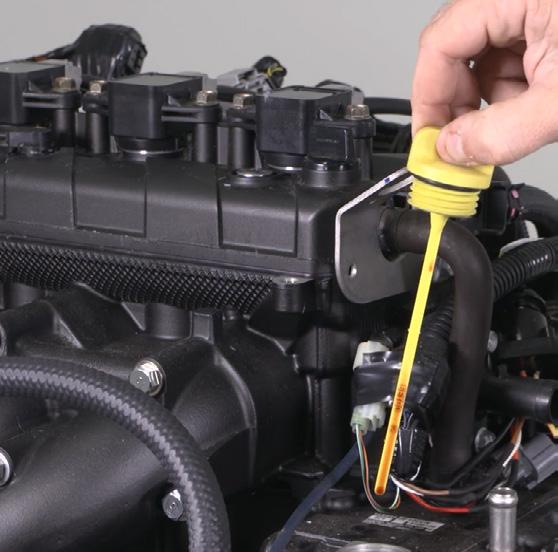
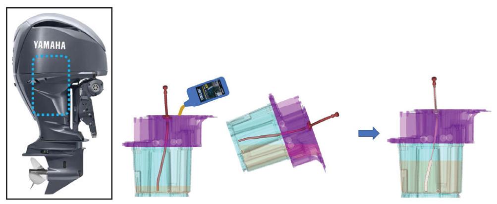
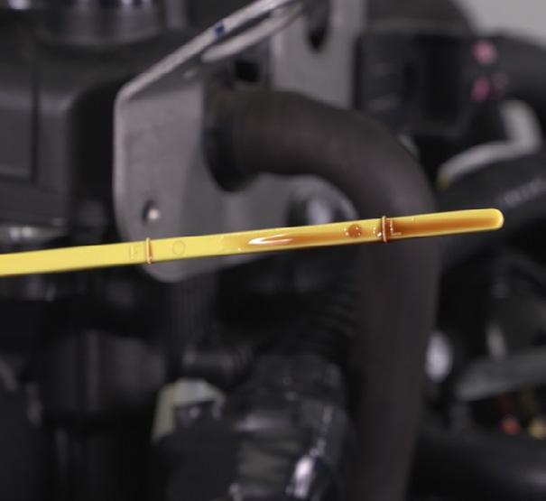
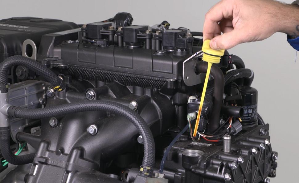
Another way to incorporate best practices into your dealership is to ensure that you are properly checking the engine’s oil level.
This pressure difference can prevent oil from entering the bottom of the tube during initial oil filling, or after oil level fluctuation events have occurred, such as during normal engine running or storage in the “tilt-up” position. Therefore, it is necessary to “vent” the dipstick tube briefly by removing the dipstick completely to allow the pressure to equalize before taking an oil level reading.
Either over-filling or under-filling the engine with oil can cause severe internal damage.
To help obtain correct engine oil levels, it is recommended to follow the below best-practice procedure:
1. Confirm the engine is level, both side to side and front to back.
2. Fully remove the oil level dipstick and wipe it clean. Wait a moment for the pressure in the dipstick tube to equalize.
3. Insert and fully seat the dipstick.
4. Fully remove the dipstick and confirm the oil level is within the upper and lower range indicators.
5. If required, adjust the oil level by adding or removing engine oil.
NOTE: Repeat steps 2–5 until the proper oil level is obtained. You can also find this procedure in Info Exchange SP2024-005.
Common Call Center Running Issue Questions with Simple Solutions
By Ron Zastocki, Technical Consultant for the Yamaha Marine Service Group
Being in the marine industry for more than 50 years, I’m often asked what are the best troubleshooting techniques that I have learned. Overall, I have found that most issues are simply due to overlooking the smaller things in pursuit of finding the major problem with a customer’s outboard motor. When this occurs, the smaller issues tend to take a back seat and are forgotten about by the time a tech has fixed the major complaint. However, as time moves forward, that small issue will often come back with a vengeance as it probably lent a hand at the original problem.
The following steps should serve as a guide to new technicians in the field and even help experienced techs find the right resource that they need in order to make certain their customer’s outboard is fully serviced.
1. Gather as much information as possible on the outboard’s history as well as the current issue by asking the following questions.
Was this worked on by someone else?
Did the customer do their own work?
What steps make the outboard perform poorly?
How long has it been happening and how long does it take for the issue to show up?
When was the last fuel up and how old was the fuel in the tank prior to taking on fuel?
How old is the battery and what are the conditions of connections?
As you gain experience, you can come up with your own list of preliminary checks to perform before starting on the job at hand. You can also retain these questions as an initial guide and, if possible, have the customer answer the questions.
2. Duplicate the issue.
This is a major step to quickly locate the source of the problem. In my experience, I have been told many times what the symptom is, only to find out it was explained incorrectly which took
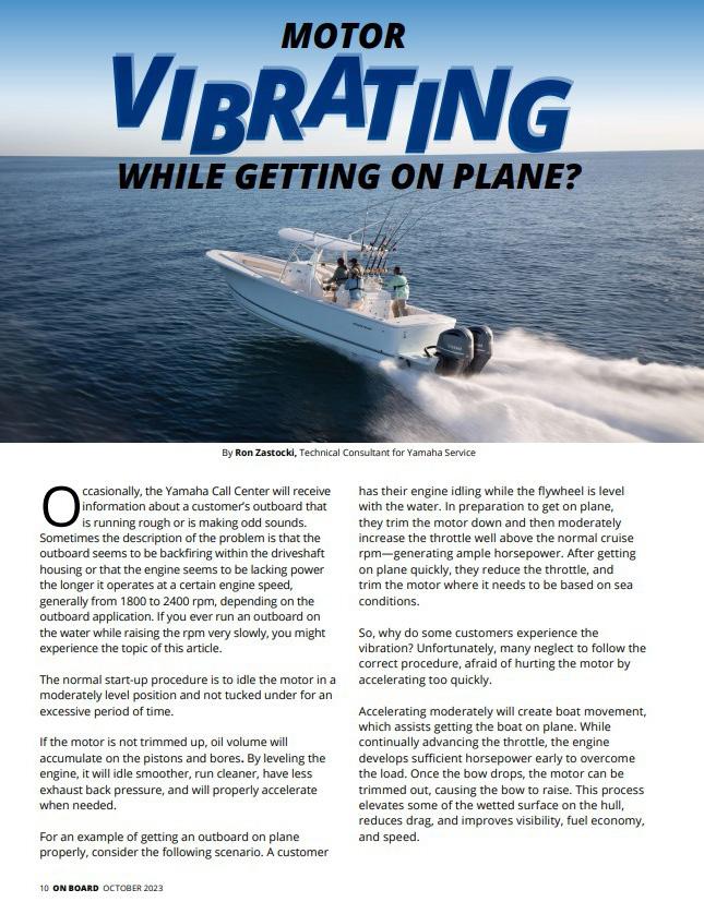
me down the wrong troubleshooting path. With out duplicating the issue, you may be searching for the perceived problem rather than seeing it firsthand. If possible, have the customer with you and allow them to duplicate the issue as the problem could be due to the way the customer operates the boat. If so, provide them with the needed instruction on operational procedures (for example, see “Motor Vibrating While Getting on Plane” in the October 2023 issue of On Board).
3. If needed, ask a more experienced technician. What does the issue seem likely to be? Is it an operational issue, propping, electrical, fuel, clogged injectors, water in the fuel, or something else? It would be impossible direct you down a certain troubleshooting path over the phone because I cannot see the issue. This is where you need to decide what path to take in order to properly diagnose the problem.
Listed below are some On Board articles I’ve written that can help you diagnose fuel related issues. Four-stroke motors that leak fuel will have fuel deposited in the oil sump. It may cause restricted wide-open-throttle (WOT) due to starvation (a lack of fuel to carburetor or injectors due to a major leak). However, in a two-stroke motor, even a minor tear will reduce rpm as the leaking fuel will be directed to the cylinder that is associated with the location of the block mounted pump fouling the cylinder.
Remember, you can find these articles in the YMBS Knowledge Center and refer to them at any time.
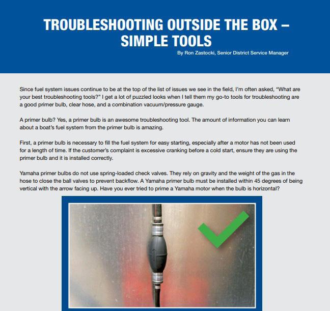
“Troubleshooting Outside the Box – Simple Tools” –November 2017
Applies to Two-Stroke Motors
Tech tip: Using the Primer Bulb as a tool.
This is actually a very common occurrence, particularly if one of the mechanical fuel pumps has a slightly torn diaphragm. Whether carburetor or EFI, if the diaphragm in a mechanical pump fails, the leaky fuel will foul out the associated cylinder with fuel.
“Troubleshooting Outside the Box – Simple Tools” – November 2017
Applies to Mechanical Fuel Pumps
This type of pump can be tested with an in-line “T” in the fuel line, a clear piece of hose, and a combo vac/ pressure gauge. Inserted prior to the pump and closing or pinching off the supply to the “T” will show the strength of the pump on the vacuum side. Installing the “T” on the pump outlet side and closing the line after the “T” will show the outlet pressure of the pump. Do you have crankcase pressure/vacuum that is in specification?
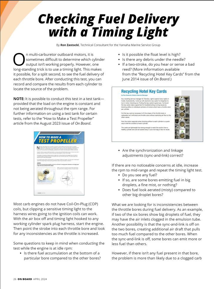
“Checking Fuel Delivery with a Timing Light” – April 2024
Applies to Two- and Four-Stroke Motors
If a mechanical pump has a bad check valve, the supply of fuel will be limited. A flooding carb can also cause that issue. The reason you can obtain WOT is because the fuel bowls or the Vapor Separator Tank (VST) is full and normal operation can resume for a short time. It’s also possible to have a check valve in the primer bulb sticking. This is generally associated with a primer bulb lying flat or collapsing from the fuel line vacuum. There may also be additional check valves in the fuel system. It’s important to know your system. The primer bulb can also collect debris as noted in “Troubleshooting Outside the Box – Simple Tools” article.
COMMON CALL CENTER RUNNING ISSUE
QUESTIONS WITH SIMPLE SOLUTIONS (CONTINUED)
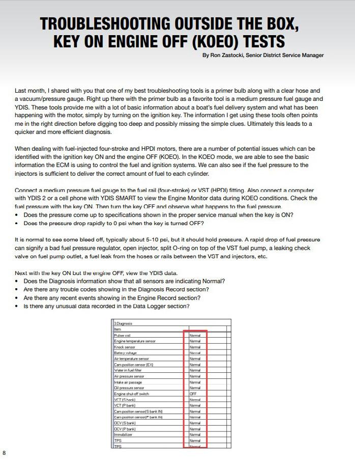
“Troubleshooting Outside the Box, Key ON Engine OFF (KOEO) Tests” – December 2017
Applies to Electric Fuel Pumps
This type of fuel pump has a check valve in-line “Teed” to the supply line for the VST. Should the pump run and fuel is not needed in the VST, the fuel will be directed back to the fuel pump inlet. If clogged or stuck, this can over pressure the VST. If stuck open, it will allow the fuel to circulate from the pump outlet to the inlet and limit the fuel to the VST.
NOTE: Do not close the outlet on an electric fuel pump.
Other helpful On Board articles:
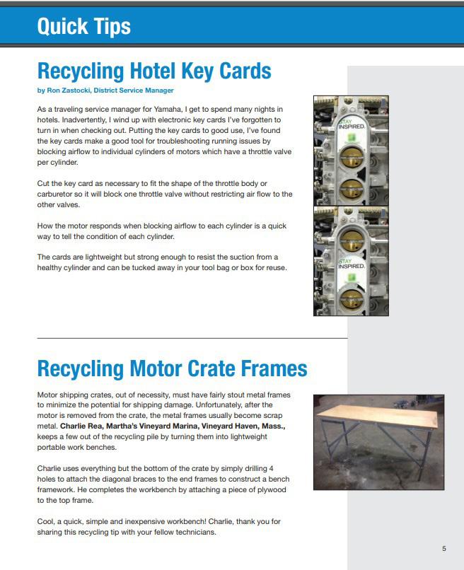
• “Recycling Hotel Key Cards” – June 2014
• “Why So Many Fuel Filters” – September 2017
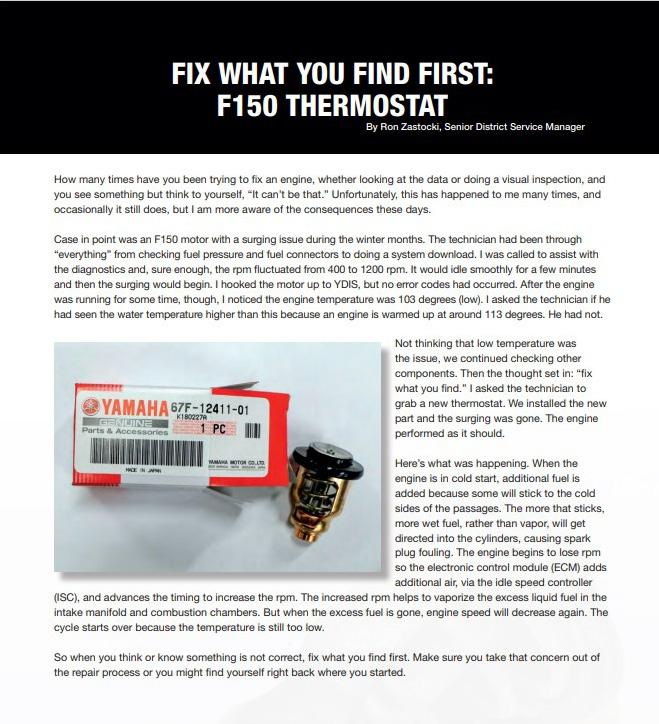
• “Fix What You Find First: F150 Thermostat” – June 2018
All of the listed articles are pieces that I have written and are from my past experiences and knowledge gained from formal education and dealers’ technicians to whom I am extremely grateful. On Board magazine is a wealthy resource, full of useful and tried information from our Technical Advisors and personnel in the field. You can also copy this list and use it as a reference guide to help you in your everyday tasks.
THE BEST PRACTICE FOR DEALING WITH A FAILED PART
From raw material to final testing and end consumer applications, it can be an arduous task to focus on the removal of all possibilities for failure in production and assembly. Consider a stainless-steel drain/ vent screw for a lower unit. How many possible failures can be found during the making of this little part? I have identified 18 potential failure points. As I presented this to the dealers in a class, a tech added one more. Some of the possibilities where failure could occur are the following: The drain/vent screw may have porosity, the slot may be too deep or not deep enough, too wide, threads not perpendicular with the underside for a gasket to seal, incorrect thread, too short, too long, and so on. This component is a perfect example because of a warranty issue where water kept getting inside the lower unit. It didn’t matter that the technician changed shafts, seals, bearing carrier, and the case itself. The root cause was a crooked drain screw that prevented the gasket to fully seat all around.
The only way for Yamaha to improve its products is through analysis of issues that arise in production and in the field. The most important questions to focus on are: Is this a one-off failure or a series of failures on a given part? What are the consequences of failures of this part in terms of reliability and customer satisfaction?
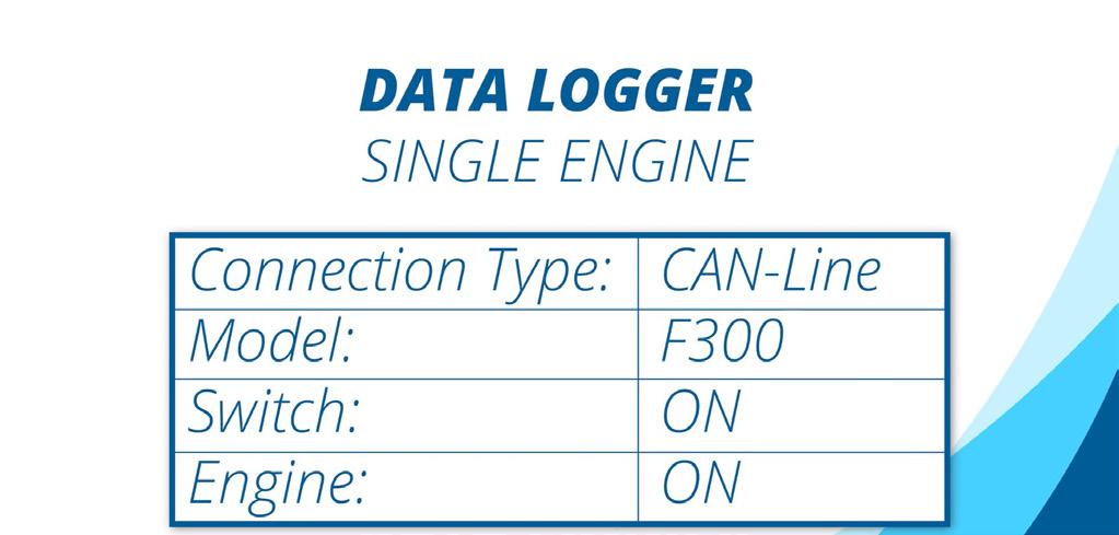
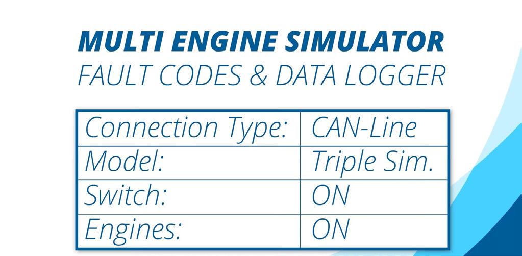
Whenever an issue arises, it is always best to practice gathering as much information as possible so the problem can be quickly corrected. That starts with your timely warranty claim that accurately describes the problem, the alleged defect, and the proper repair. One of the most significant pieces of information that you can collect for a Yamaha Technical Advisor is the data log from YDIS. From this report, they will be able to see when failures are occurring. Is it at 20, 200, or 700 hours? By looking at the data log, we can also observe if it’s a running quality issue by viewing the rpm ranges, shift cycles, starting cycles, etc. For more information about how to collect a data log, simply scan the QR Codes below.
THE BEST PRACTICE FOR DEALING WITH A FAILED PART
As a result of analysis and testing of good and failed parts, many positive changes can enhance product quality. Going forward, should you need to file a warranty or Y.E.S. claim, please capture a data log of the outboard motor and submit it with the claim. In addition, provide photos or videos to help support your findings. Also specify the engine position on the boat (P, CP, C, CS, S) and any other specific information that can support the investigation. This will streamline the process and enhance the claim processing time. This will reduce making phone calls or emails back and forth trying to obtain the download. We need a data log for all claims as explained “YDIS Downloads and Warranty Claims” from June 2022 On Board or “YDIS Downloads for Claims” from August 2018 On Board.
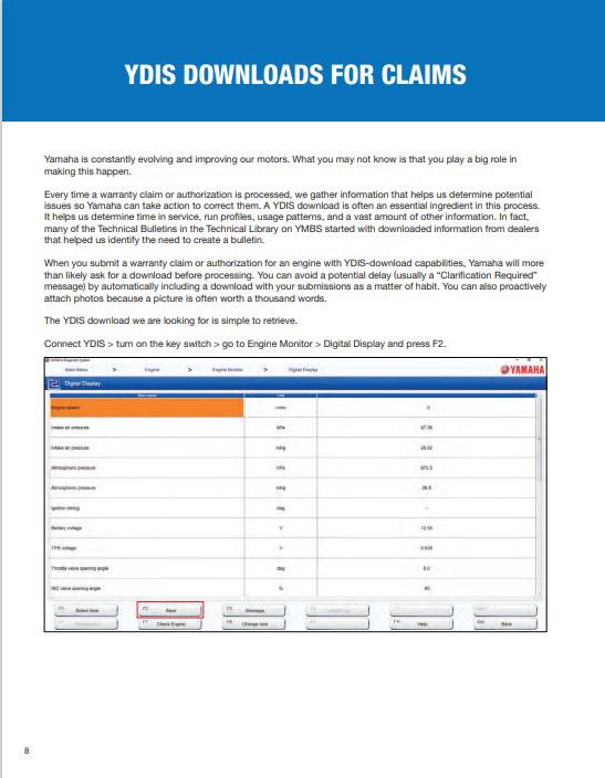
“YDIS Downloads for Claims” from August 2018 On Board
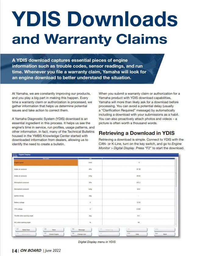
“YDIS Downloads and Warranty Claims” from June 2022 On Board
Yamaha is driven to provide Marine products that have the fewest issues and outstanding out of the box quality. To keep our products at the top of the list, we need your assistance with keeping Yamaha as the best in the marketplace.
HOW DEEP DO I NEED TO BE?
Running in a Bucket
By Ron Zastocki, Technical Consultant for the Yamaha Marine Service Group
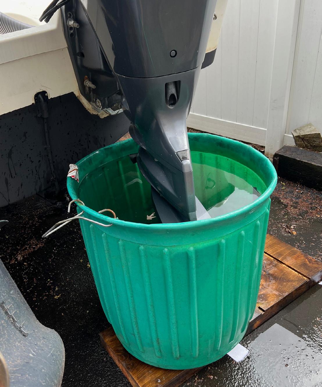
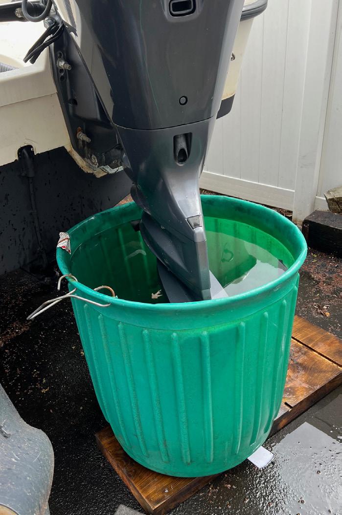
We encountered a situation where a dealer performed all the necessary winterization procedures, as well as replacing the water pump and thermostats. After the winter maintenance procedures were completed, the customer took the twin-outboard boat home for storage. In the spring, the customer placed each unit in a bucket of water and ran the engines separately. One engine ran well, while the second engine’s alarm for overheating went off. The customer could not get the motor to pump water. After returning the outboard to the dealer for inspection, it was noted that the water pump was burned.
The customer was perplexed as to why one engine ran well while the other burned the impeller and water pump housing. The dealer installed a new pump and launched the boat and all systems worked fine. However, the customer was still uneasy as to why this happened in the first place.
The customer provided a picture of the motor in the bucket almost filled to the top with water. This scenario is unfortunately common, where there is not enough water in the bucket to get the water pump primed.
There are two reasons:
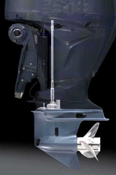
As we look at the cutaway picture, we can see the water pump is well above the antiventilation plate and the top of the pump is about three inches above the split line, where the lower unit meets up with the upper housing.
To have the water pump work correctly, the water level should be a minimum of three inches above the split line to fully submerge and prime the pump. This raises the question: “Why does the motor not overheat while the boat is on-plane, and the water pump is out of the water?”
1. The pump has been initially primed when it was in deeper water. As water is expelled from the impeller blade being compressed, a low-pressure area is created as the impeller opens up while running eccentric.
2. As the lower unit moves through the water, ram pressure at the intake screens forces water to the water pump while going forward. In reverse, the engine is lower in the water with the pump submerged once again.
Although running the engine in a bucket is an excellent way to allow the engine water pump to function on its own, it is necessary to replicate how the engine runs at the dock, and that is with the water pump fully submerged.
For more information, refer to “Why Flushing Matters” in the October 2023 issue of On Board.
HOW TO REMOVE WATER FROM A TR-1 ENGINE
Maintaining the functionality of a customer’s watercraft is a critical responsibility as a marine technician. One way to keep it running smoothly is to ensure that there is no water intrusion present in the unit. In this article, we will provide you with a step-by-step guide on how to remove water from the TR-1 engine.
Step 1: Inspect for water intrusion.
• Remove the air filter and inspect it for water intrusion.
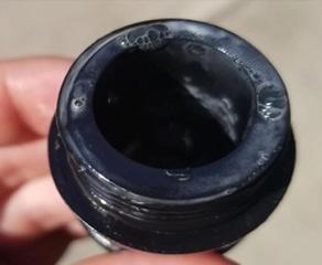
• Inspect for signs of water intrusion by removing the oil dipstick. If the oil looks like the photos shown here, it is contaminated with water.
• Remove the spark plugs to check for signs of water. This can be done by using a 10 mm socket to remove the bolts, then remove the ignition coil connections. Then remove the spark plugs using a 5/8” socket. For easier spark plug removal, use their ignition coils to pull them out.
Step 2: Remove water from pistons.
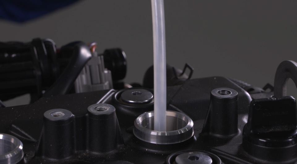
• Insert the hose from a vacuum pump into the spark plug holes to suck out any water that may be on top of the pistons.
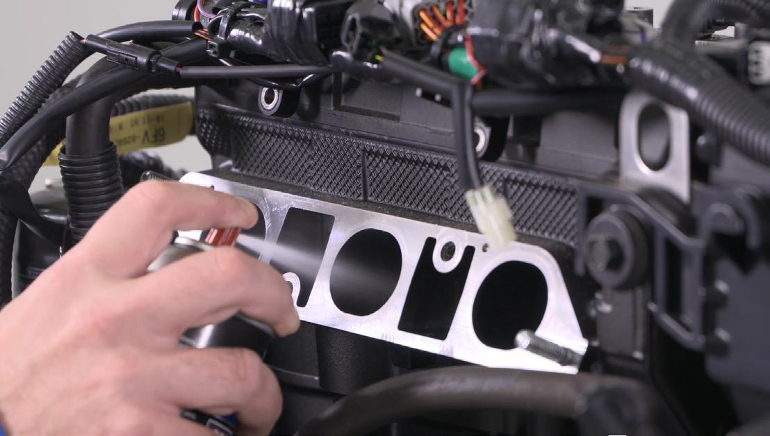
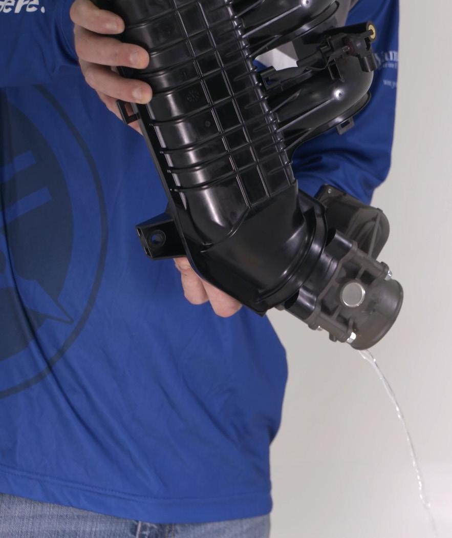
Step 3: Remove water from the intake manifold.
Before checking the fuel system, remove the battery, and then remove the fuel filler cap to reduce any pressure inside the fuel tank.
• Empty any remaining fuel and pressure out of the fuel rail. WARNING: Make sure to disconnect the quick connector slowly. Otherwise, pressurized fuel could spray out. Make sure to clean up any fuel spills.
• Remove the fasteners that hold the intake air pressure sensors and exhaust.
• Disconnect the air pressure sensors and exhaust.
• Use a flathead screwdriver to remove the throttle body clamp, and then disconnect the throttle body connector.
• Then, remove the fuel rail and intake manifold’s hardware.
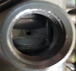
• Check for any remaining water in the intake manifold.
Completely remove ALL water from the intake manifold. Any water left in the intake manifold will result in damage when attempting to start the engine.
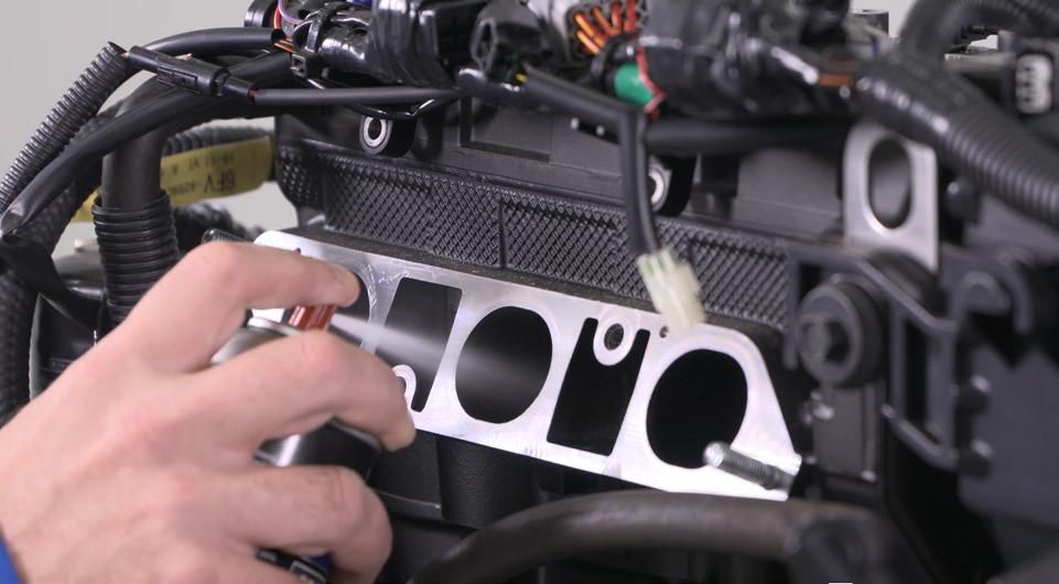
Step 4: Lubricate the cylinders, intake valves, and throttle body.
• Use Yamalube® Fogging Oil to lubricate the cylinders, intake valves, and throttle body. Doing this reduces traces of corrosion from water intrusion.
• Spray Yamalube Fogging Oil into each cylinder for 2-3 seconds each.
• Spray the intake valves with a light coating.
• Reinstall the intake manifold, fuel rail, and injectors.
• Secure the wiring harnesses to their holders.
• Install the spark plugs and ignition coils.
• Reconnect the battery.
• Leave the fuel injectors and coils disconnected.
• Use the start button to roll the engine over for several seconds. Doing this will allow the fogging oil to coat the cylinder walls and lubricate the valves.
• Connect the fuel injectors and ignition coils.
Step 5: Start-up
• Be sure to move the unit outside prior to start-up. The fogging oil will cause the engine to produce excessive amounts of smoke.
• If water is still present in the oil, you will need to change it multiple times until the water contamination is gone.
Remember, we are here for you! For more information about this procedure, refer to the Service Manual. If you need assistance from a Technical Advisor, you can visit the Knowledge Center and click on the submit a Tech Request for further assistance.
Yamaha has prepared a service video regarding this process. Scan the QR Code or go to TR-1 Engine - Removing Water on Vimeo
https://vimeo.com/633189608/b4b193cbb6
How to Submit a QA Claim for WaterCraft Parts and Accessories
By Kyle Hoffman, Marine Warranty Coordinator
When you need to submit a Quality Assurance Claim for a failed part or accessory, we understand that each submission is important and that you want a resolution as quickly as possible. We are here to help! To ensure that your claim progresses as quickly as possible, it is important to attach a legible copy of the retail receipt, attach high-quality photos of the failure, if applicable, and ensure the claim is filled out as accurately as possible.
NOTE: For more information about Quality Assurance, please refer to the Yamaha Parts and Accessories Limited Warranty statement (P/N: LIT-18791-PA-17), and page 11-1 of the Yamaha Dealer Support Guide (P/N: LIT-10080-07-16), both available in the Knowledge Center on YDS.
It’s important to note the following before submitting a QA Claim:
• Coverage is for the dealer cost of the part or accessory only. Labor is not covered.
• Failure Date must be within 1 year of the date of original retail sale.
• Yamaha may recall the claimed parts. However, please do not return any item unless it has been specifically requested for return.
• Claims resulting from shipping damage must be submitted as a Parts Return Credit Request.
IMPORTANT: Quality Assurance is for Yamaha Genuine parts and accessories that are sold retail, either over the counter or installed by your dealership, that have failed due to a defect, as long as the terms and conditions of the Yamaha Parts and Accessories Limited Warranty are met. Original equipment parts and replacement parts installed as part of a factory warranty repair are not covered by QA.
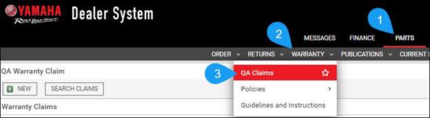
To submit a QA Claim, from the Home Page of YDS, click: Parts > Warranty > QA Claims.
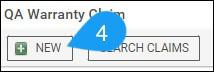
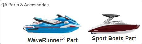
Select the applicable product. Click “New”
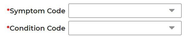
Select the correct Symptom and Condition Code (Part or Accessory) from the drop-down option.
Then, fill out the rest of the required fields in the General Information, Failed Parts, Primary Failed Part, and Specific Request Information boxes.
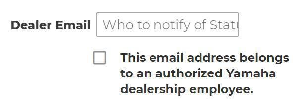
NOTE: To receive status updates about your claim, input your email in the Dealer Email field and check the box below it.
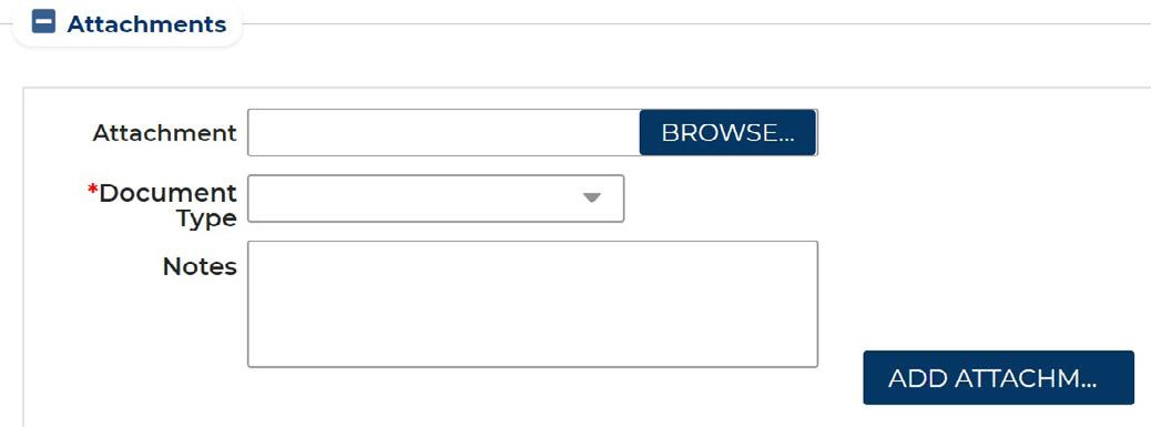
Once all the information is entered, upload a copy of the retail receipt and photos to support the QA Claim.
NOTE: When uploading attachments, select the appropriate “Document Type” and the click the “Add Attachment” button. You must at least attach the retail receipt in order to submit your claim.
The last step is to click the “Save & Submit” button to submit your claim to Yamaha for review.
Remember, warranty covers manufacturing defects in material or workmanship. As a dealer, it is your responsibility to determine if the failure is a warrantable defect that has occurred during the warranty period, and that it is not the result of any of the exclusions listed in the Yamaha Parts and Accessories Limited Warranty statement.
How to Perform a Data Log for Fuel-Injected WaveRunners
When diagnosing poor performance or rough running conditions in a fuel-injected WaveRunner, it is essential to first conduct a water test and perform a data log with the Yamaha Diagnostic System 2 (YDIS2) adapter. This article will guide you on how to properly set the YDIS2 adapter for accurate data logging.
You will need:
• Laptop with Windows® 10/11 OS
• YDIS2 Ver. 2.49 or Higher Software
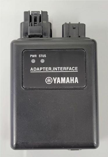
• YDIS2 Interface Box
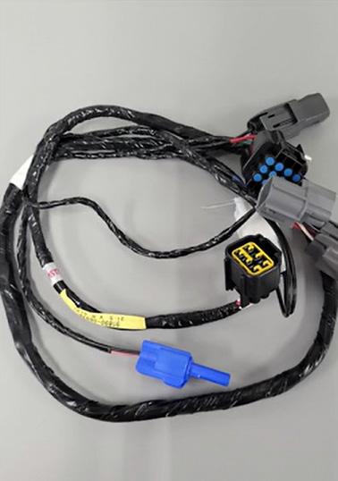
• K-line Harness
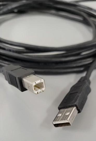
• USB-to-Printer Style Cable
If you require assistance installing the YDIS2-software or need replacements for any of these items, please contact the Watercraft advisors at (800) 879-0078, option 2.
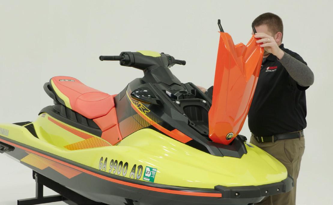
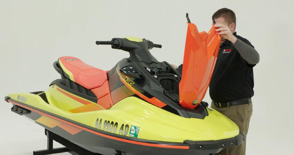
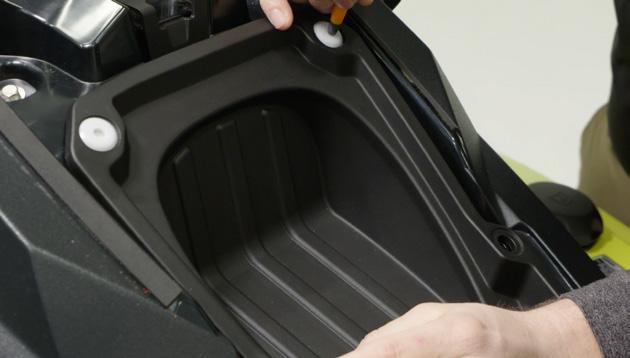
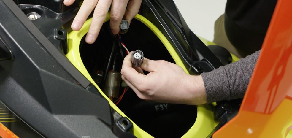
1. Here is an example of the procedure, using an EXR model as an example: Start by opening the front hatch and removing the storage compartment.
2. Press the center section of the body rivets so they can be removed.
3. Disconnect the meter connector from the harness and connect the K-line harness. Refer to the service manual if you are having trouble finding the connector.
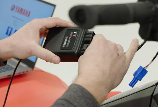
4. Connect the K-line harness to the YDIS-2 interface box, then connect the interface box to your laptop using the USB cable.
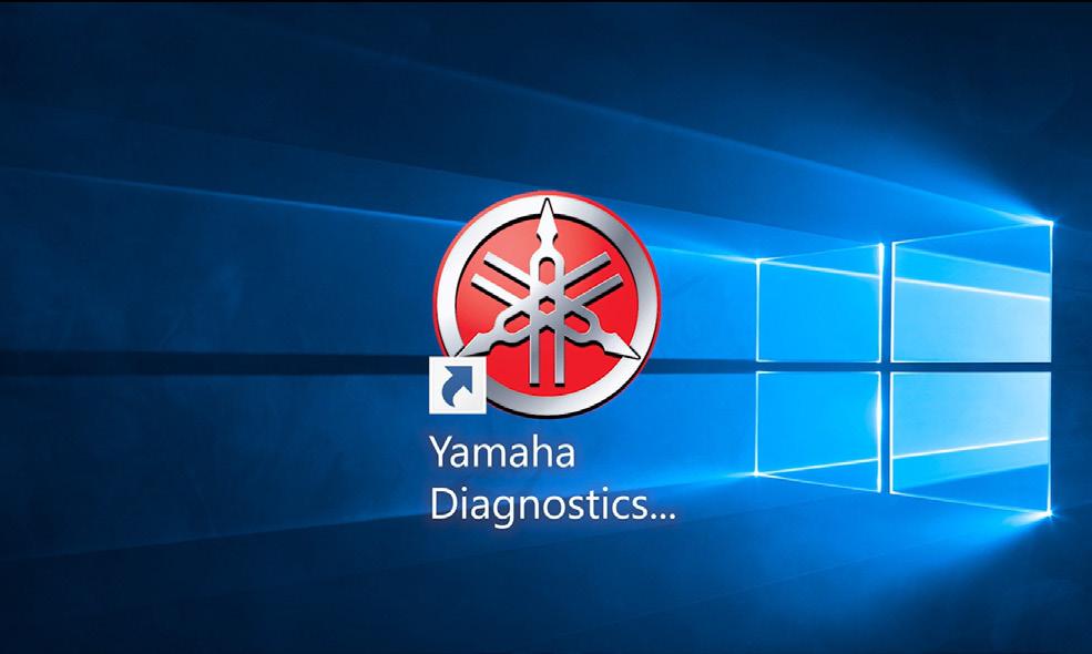
5. Now, you will need to start the YDIS, click the application that is depicted above.
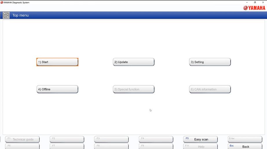
6. When the application opens, select the WaveRunner logo to take you to the Top menu, then select the “Start” button.
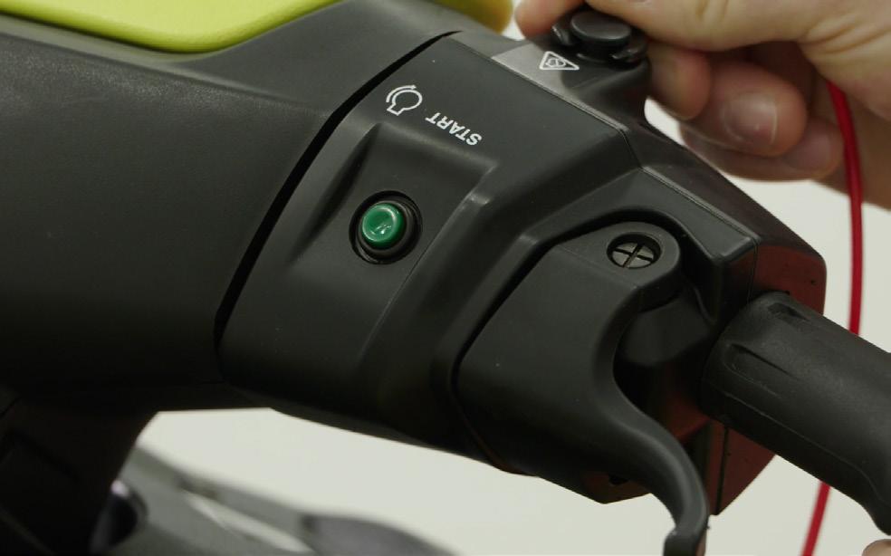
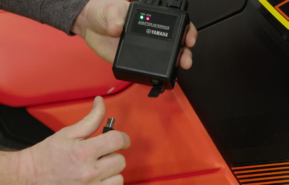
7. Next, insert the lanyard and press the green start button to power up the ECM.
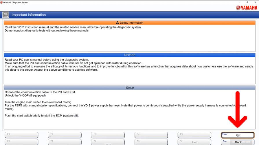
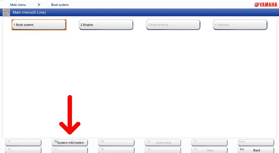
8. On the YDIS application select “OK” then select “System Information.”
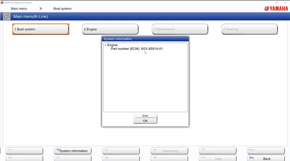
9. A window should open showing the ECM part number that is needed to set up the data logger. Be sure to write the part number down.
HOW TO PERFORM A DATA LOG FOR FUEL-INJECTED WAVERUNNERS
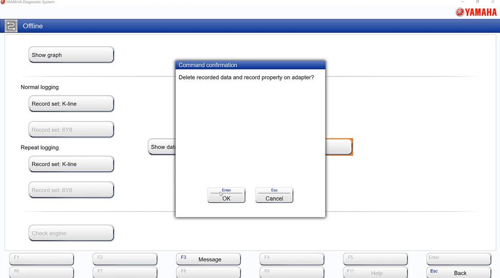
10. Push the ESC button to get back to the main menu, select the “offline” option, then select the “clear data” option. Selecting the “clear data” option will delete all recorded data and record property on the adapter. Doing this will ensure that there is enough memory for the recording.
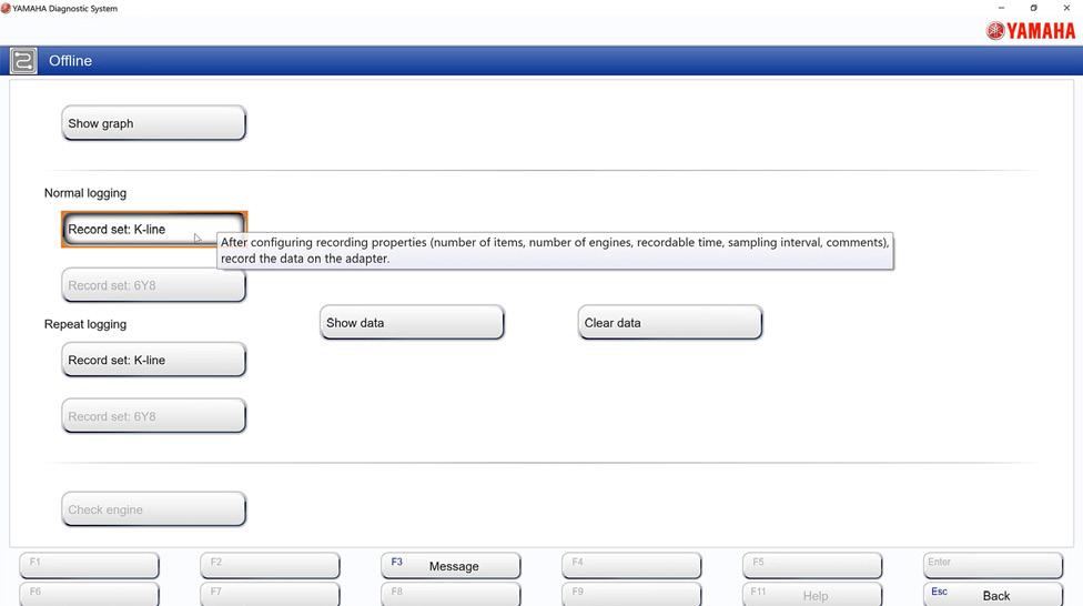
11. After clearing the data, select the “Record set: K-line” button.
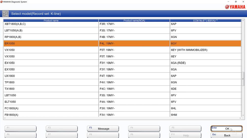
12. Next, select the proper ECM part number (the one written down from step 9) from the list, then select “OK.”
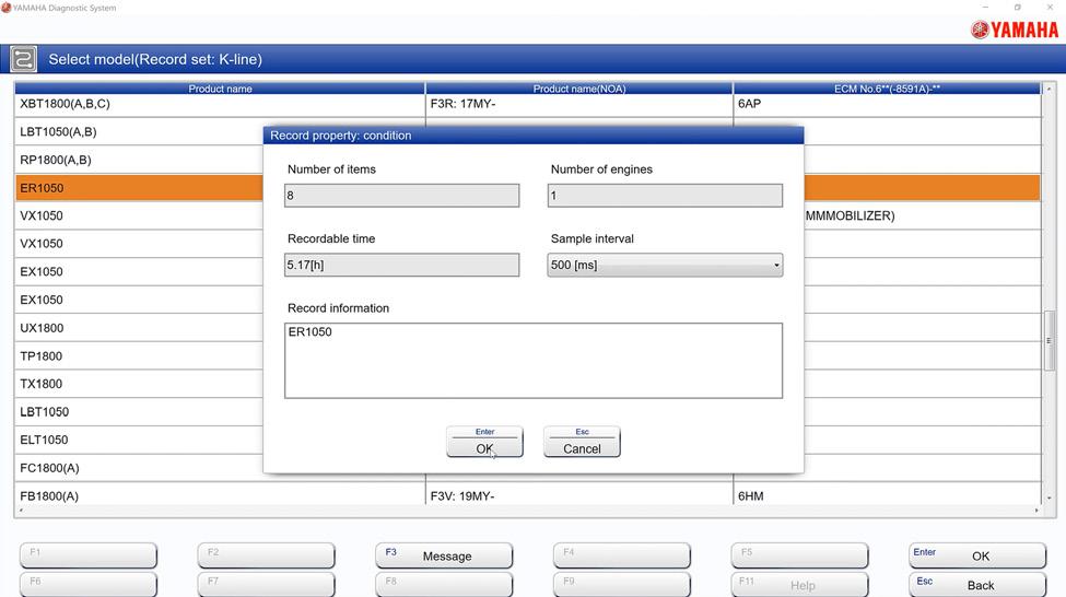
13. Now, you can select up to eight sensors you want to record.
14. Be sure to set the sample to “500[ms].” Recordable time is affected by the number of sensors you select, more sensors selected will result in less recordable time. After you are finished selecting your settings, you are ready to record.
15. Disconnect the USB cable from the adapter, then place the adapter in the WaveRunner to avoid water contamination.
16. When you start the engine to perform your water test, the adapter will start blinking. The blinking indicates that the recording has begun.
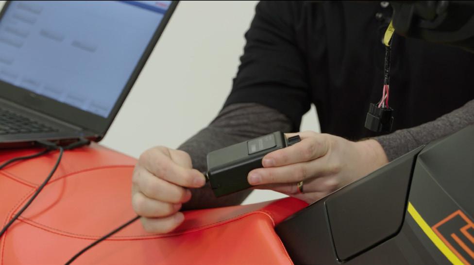
17. After the water test is complete and you are ready to review the data log, you can disconnect the adapter interface from the unit, then connect the adapter to the laptop. Then open the YDIS application.
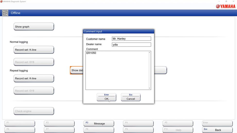
18. After opening the YDIS application, select the WaveRunner logo, then select “Offline.” Click “Show data, and then enter the customer’s name for reference. Save the file to the laptop for easier access.
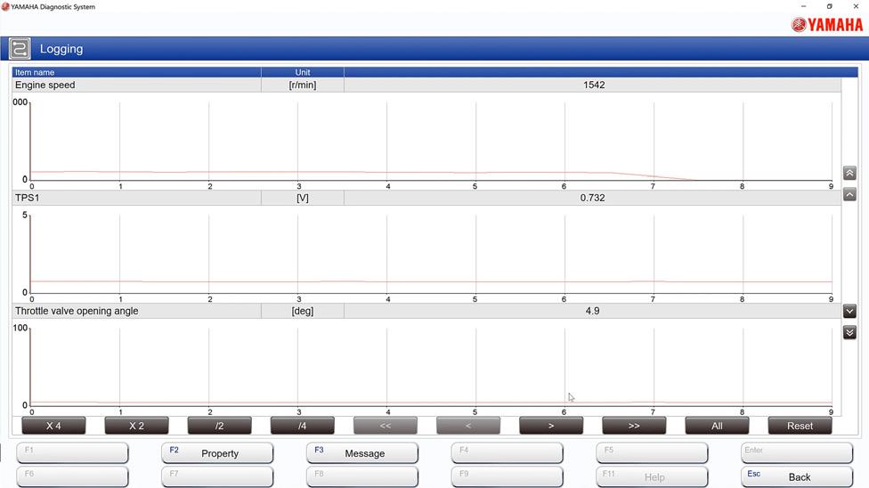
19. Once saved, the data log file will appear allowing you to view the sensors you recorded.
This procedure can also be viewed by clicking the link or scanning the QR Code.
https://vimeo.com/801001602/b34501bb84
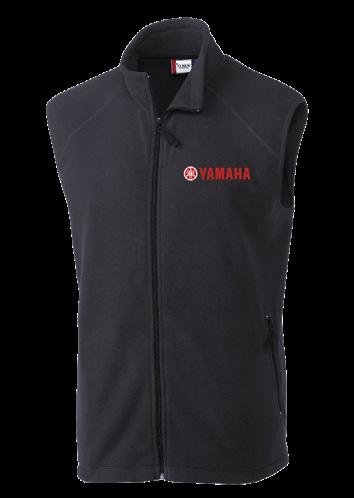
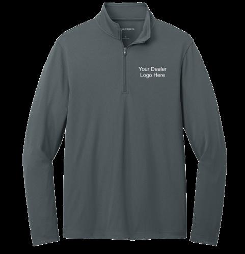
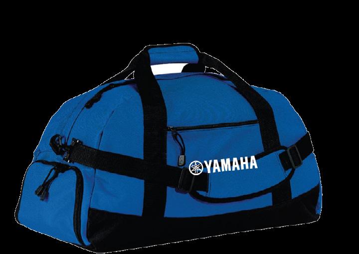
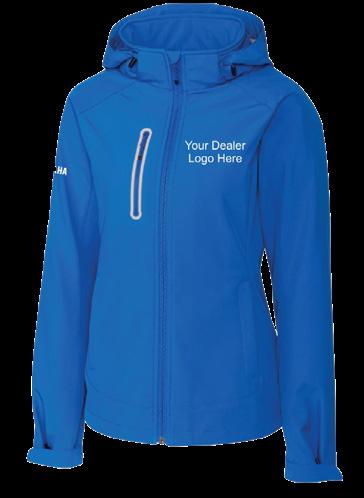
YAMAHA’S ONLINE TECHNICIAN AND DEALER STORE
As the weather is turning colder, our technician and dealer store is ready to supply you and your team with all the necessities. From duffle bags to co-branded jackets, we have you covered! Take a moment to browse our warm and comfy selections of hoodies, vests, and more to get your dealership ready for the fall season!
Start shopping today at store.ymutechs.com. Please allow three weeks for processing and delivery of most items. Co-branded technician uniforms with the dealer’s logo can take up to six weeks. Scan the QR Code®* to go directly to the online store.
Have comments? Contact us! Please email comments to Marine_On_Board@yamaha-motor.com. When you subscribe to receive printed copies of On Board, we mail the magazine to the address you enter in your Tech Hub profile. If you need to update your mailing address to continue receiving your bi-monthly copy, it only takes a few minutes to make the changes. Please allow about one month for mailing changes to be implemented.
1. Click the Settings icon in the upper right corner of the screen.
2. Click Profile
3. Click Edit Profile on the right side of the screen.
4. Enter your mailing address in the Contact Information section.
5. Click Save in the upper right corner of the screen.