In addition to the digital copies of On Board always available in the Knowledge Centers and Tech Hub, we also make printed issues available for every dealer and technician who wants them. Sign up for a free subscription if you aren’t getting them!
Subscribe to On Board
1. Access the subscription form with this link: http://tiny.cc/SubscribetoOnBoard.
Or scan the QR Code to the right with your mobile device.
2. Fill out the form.
TIP: Be sure to fill out ALL of the fields as directed. There are separate fields for your street address, city, state, and zip code. Enter each item into the correct field to ensure your mailing address is entered in our system correctly.
3. Double-check your information and click “Submit” when you’re finished.
Dear Marine Professional,
As we are in the beginning of the new year, it is a great time to revisit our “Back to Basics” resources. This will enable dealers and technicians to reestablish a firm foundation for certain basic service procedures such as maintenance, troubleshooting, and more.
When working on any type of issue, whether it be mechanical or electrical, try to not overthink the problem. The word “problem” merely identifies the gap between the current situation and the desired outcome. Here at Yamaha, that is what the word “problem” represents. So, what are some ways that you can successfully assess a situation to identify what it will take to move into a desired outcome? Sometimes, all it takes is to take a step back and remember the basics. One way to brush up on the basics is to attend a YMU course or enroll in an e-learning course.
YMU courses are designed to train students to obtain the competencies that will help them assess and identify a “problem,” properly execute the correct service procedure, and successfully move toward the desired solution. To give students a structured back-to-basics foundation, our training department designed the Service Skills Training (SST) maintenance course, available for Outboard and WaterCraft. SST is a course on maintenance services such as oil changes, fuel filter changes, and spark plug replacements. However, it also offers more in-depth maintenance training, such as how to
If you need help learning how to sign up for courses, check out our new YMU User Guide by scanning the QR Code or clicking the link. We look forward to seeing you in class!
successfully inspect and replace the timing belt or water pump.
It is imperative, for the success of any dealership, that dealers and technicians are equipped with the knowledge and technical training on how to correctly diagnose and perform service procedures. To that effect, YMU has created an educational pathway that targets specific areas of our products that will guide each student from a “Practiced” to “Advanced Technician,” and then to a “Master Technician.” Be sure to contact our training department or scan the QR Code below for more information on how you can register for classes today.
Additionally, our Knowledge Centers provide ample resources to ensure that you can look up any best practices to review such as past On Board magazines, Info Exchanges and Technical Bulletins, and Service Videos. To check out any or all of these sources of back-to-basic information, simply login to YMBS or YDS, locate the “Knowledge Center” tab, and use the search bar or category side bar to locate whatever you need.
Remember, Maintenance Matters®! Proper maintenance, completed at regular service intervals, helps protect the value of the customer’s investment and provides years of trouble-free fun on the water. As always, Yamaha Marine remains committed to providing top-quality, service-based resources designed with your success in mind. We hope that 2025 holds a great and prosperous season for you, and remember, we are here to help!
Sincerely,
Joe Maniscalco General Manager Yamaha Marine Service Division
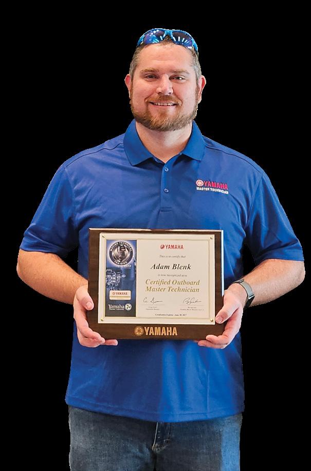
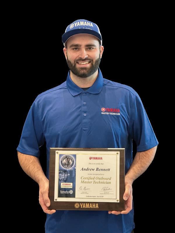
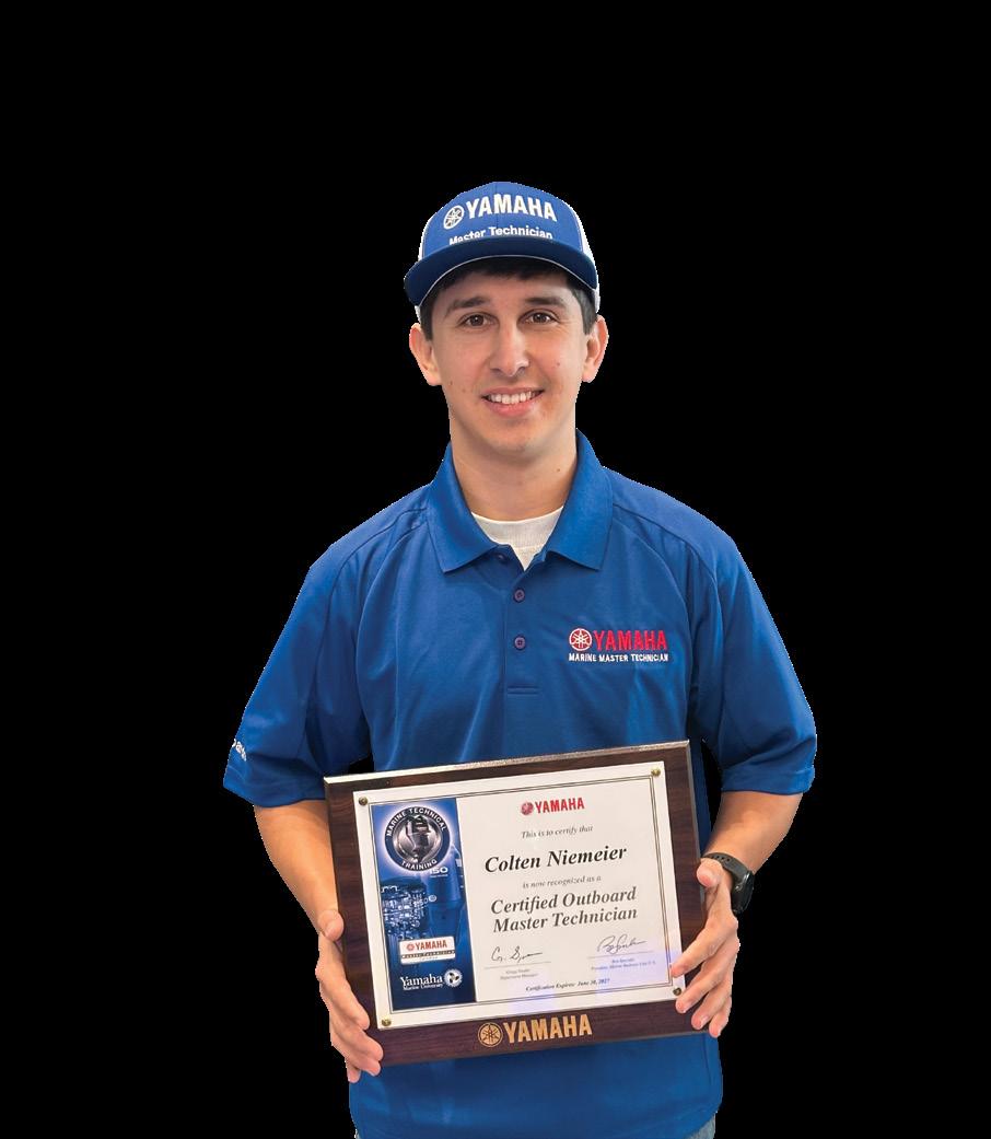
The Yamaha Master Technician certification is a prestigious status earned by dedicated, hardworking, and experienced technicians. To earn this title, experienced marine technicians must successfully complete six weeklong courses after which they are eligible to take the Master Technician exam. Technicians who have obtained Yamaha’s Master Technician status have worked hard to hone their knowledge of Yamaha outboard motor operating systems, proper installation, and service and maintenance procedures, plus troubleshooting skills. Technicians who have qualified to take the Master Technician Certification test can affirm how challenging the test really is. We would like to recognize and congratulate our most recent technicians earning Master Technician status after they successfully completed the exam.
Ready to become a Yamaha Outboard Master Technician? Make sure you’ve completed the required training courses to qualify for the exam. Check your transcript on Tech Hub (ymutechs.com) or YMU Online (yamaha-motor-university.com/YMU/).
DYLAN FLOWERS
FOOTHILLS MARINE OF LAKE NORMAN MOORESVILLE, NC
MICHEAL PEARSON HORRY-GEORGETOWN TECHNICAL COLLEGE CONWAY, SC
SHILTS
YAMAHA DSM PLEASANT PRAIRIE, WI
NATHAN YORK
TOONS GRAND LAKE, LLC GROVE, OK
MURRAY PRO MARINE, INC. SARASOTA, FL
RYAN CHERBONNIER
COMPOSITE YACHT, LLC EASTON, MD
JAMES
LOGAN
TECH TIP CORNER
Back to Basics: The Importance of Flushing
This tech tip, from our Customer Relations team, is a “Back to Basics” reminder of how important it is to inform your customers to flush their outboard motor after each use. For new boaters, be sure to point out the location of the convenient built-in flushing attachment on the motor before relaying the steps below.
Flushing the Motor with the Built-In Flushing Attachment
Do not perform this procedure while the engine is running. The water pump may be damaged and severe damage from overheating can result.
1. If the boat is remaining in the water during flushing, tilt the outboard motor up until it is completely out of the water. This will allow the fresh water to flush out the water and exhaust passages in the midsection and lower unit that would otherwise remain below the water level.*
2. Disconnect the freshwater flush adapter hose from the fitting on the bottom cowl.
3. Connect the freshwater flush adapter hose to the garden hose.
4. With the engine off, turn on the water supply and let the water flush through the cooling passages for about 10 to 15 minutes.
5. Turn off the water supply and disconnect the freshwater flush adapter hose from the garden hose. Reattach the freshwater flush adapter hose to the fitting on the bottom cowl and tighten it securely.
If the freshwater flush adapter hose is not properly reconnected to the fitting on the lower cowling after flushing, cooling water can leak out of the flushing hose and the engine can overheat, causing severe damage
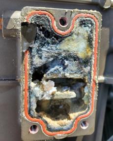
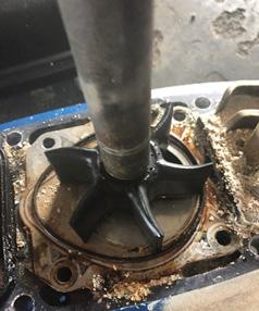
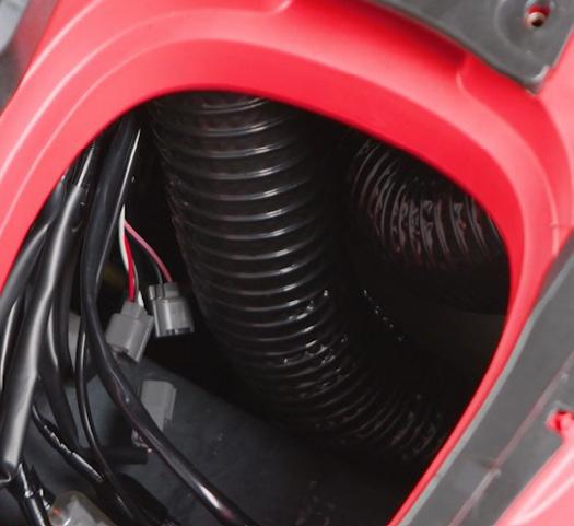
It is best to perform this maintenance procedure after each use. Built-up debris and deposits will stay in the motor if it’s not properly flushed out and can damage the unit as seen in the pictures below.
Remember, you can always refer your customer to the “Maintenance” section in their outboard’s owner’s manual for this procedure and more in-depth information. Additionally, you can watch our “Fresh Water Flushing–Maintenance Matters” service video by scanning the QR Code below.
https://www.youtube.com/ watch?v=ZJaTjMOEKP0
KNOW? DID YOU
YDIS TECHNICAL GUIDE
By Van Sherman, Yamaha Product Engineer
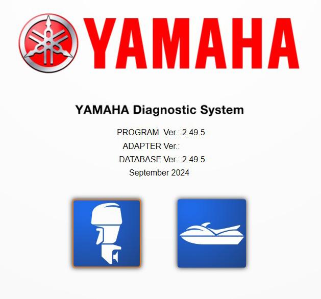
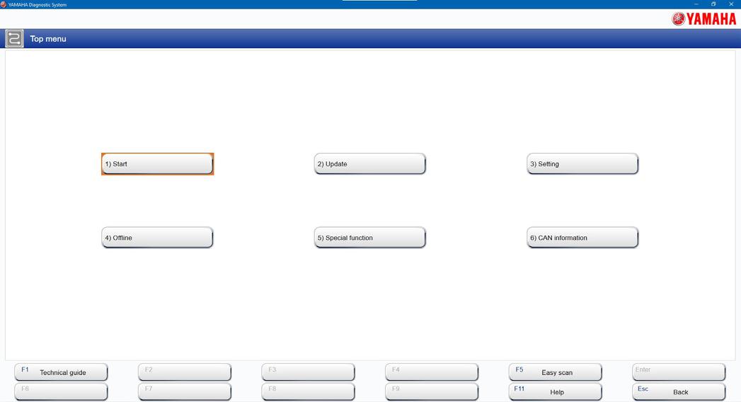
Did you know that YDIS is not just a diagnostic system? It also has extra features, such as the “Technical Guide,” that can help you and your technicians better understand the ins and outs of Yamaha Outboards.
To access this amazing feature, simply open the YDIS application on your computer. Then click on the blue outboard.
From here, click on the “Technical guide” on the bottom left corner or the “F1” button on your keyboard.
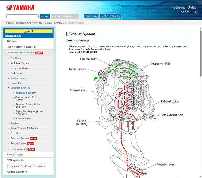
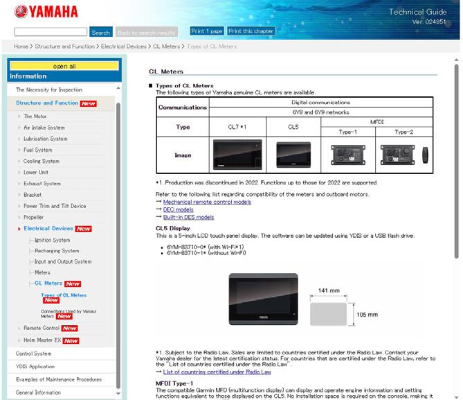
This will open a new window where you can access all kinds of information. For example, detailed diagrams showing how the exhaust system works, different types of Command Link® (CL) displays, and much more!
I encourage you to take a moment to explore this amazing tool. Not only can it enhance your knowledge on how to better service your customer’s outboard motor, but it is a great way to get a closer look at how some of our more complex systems work.
NEW PRODUCTS Ringing in the New Year with
Yamaha is pleased to announce the following new products and updates that will continue to ensure that our customers have the very best boating experience in the industry.
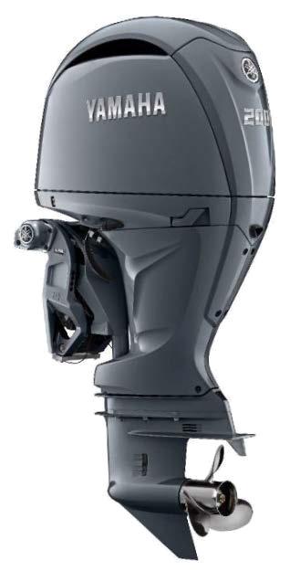
New Engine Options for F150/200 Models
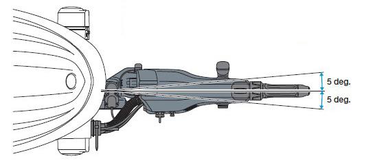
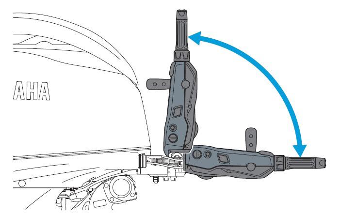
The new F150XHA and F200XHA models incorporate a feature-rich, power-assisted tiller handle. Paired with the electro-hydraulic steering system introduced in 2023, the new mechanical steering-assist tiller handle engages an electric steering sensor that triggers the outboard's integrated electro-hydraulic steering system. At or above 2000 rpm, the steering sensitivity can be set for lighter, effortless steering to reduce arm strain during long runs.
To promote comfort and convenience for captains of various physical sizes and to accommodate different boat load scenarios, the new steering-assist tiller handle can be adjusted up to 15 degrees port or starboard from center in 5-degree increments, whereas the height adjustment screw allows the tiller arm to be raised or lowered parallel to the boat deck or captain’s seat to modify according to captain seating preferences.
The tiller arm can also be folded and locked vertically 90 degrees at its mounting base, allowing upright tiller arm steering during loading, and trailering.
The standard-length tiller is included in the engine crate. However, you will need to order the appropriate "fitting kit" dependent on the desired handle length, standard, which includes just the necessary control cables and wire harness, or the 8" extension kit that also includes the tiller handle insert.
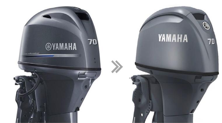
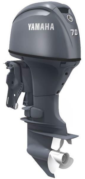
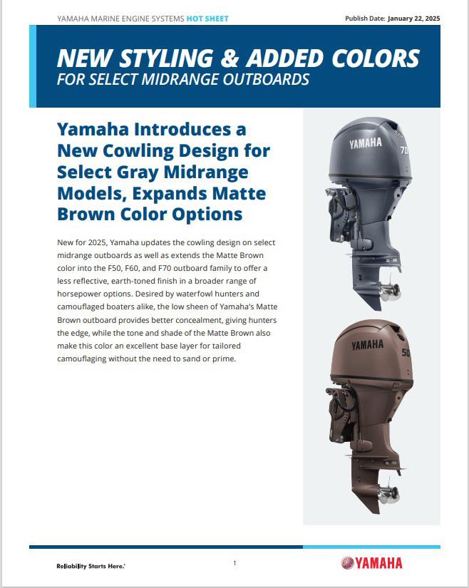
Design and Color Updates!
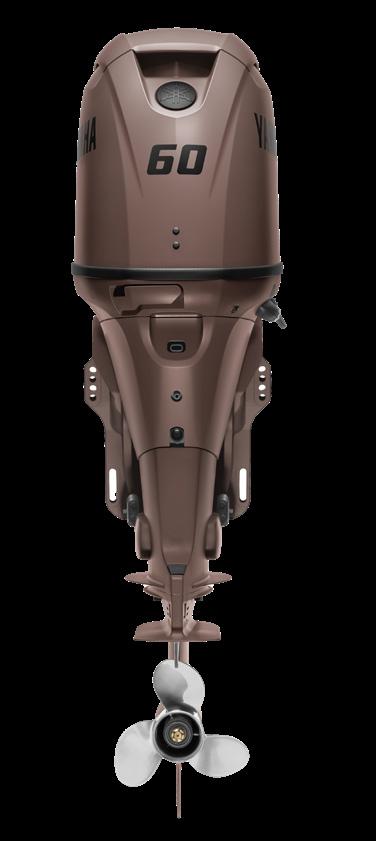
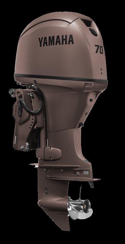
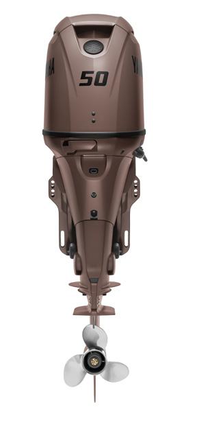
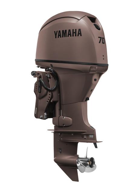
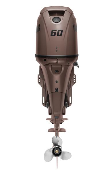
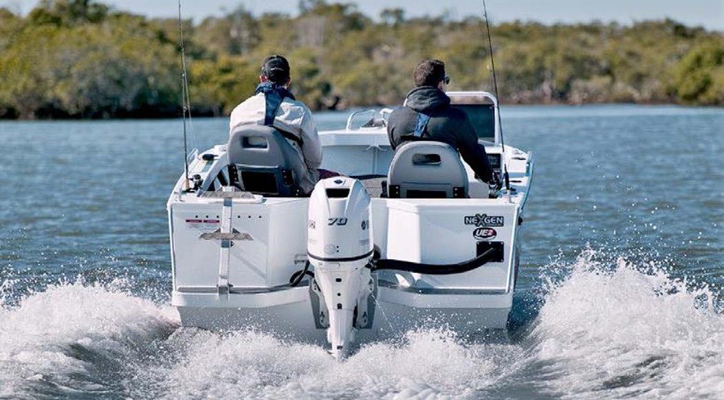
F50/ T50/ F60/ T60/ F70
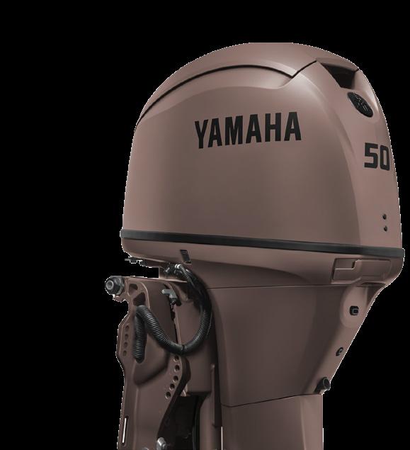
This new year, Yamaha’s F50/ T50/ F60/ T60/ F70 models are adopting the modern and sleek design to match our more highly powered outboard motors— giving our product line a more unified feel.
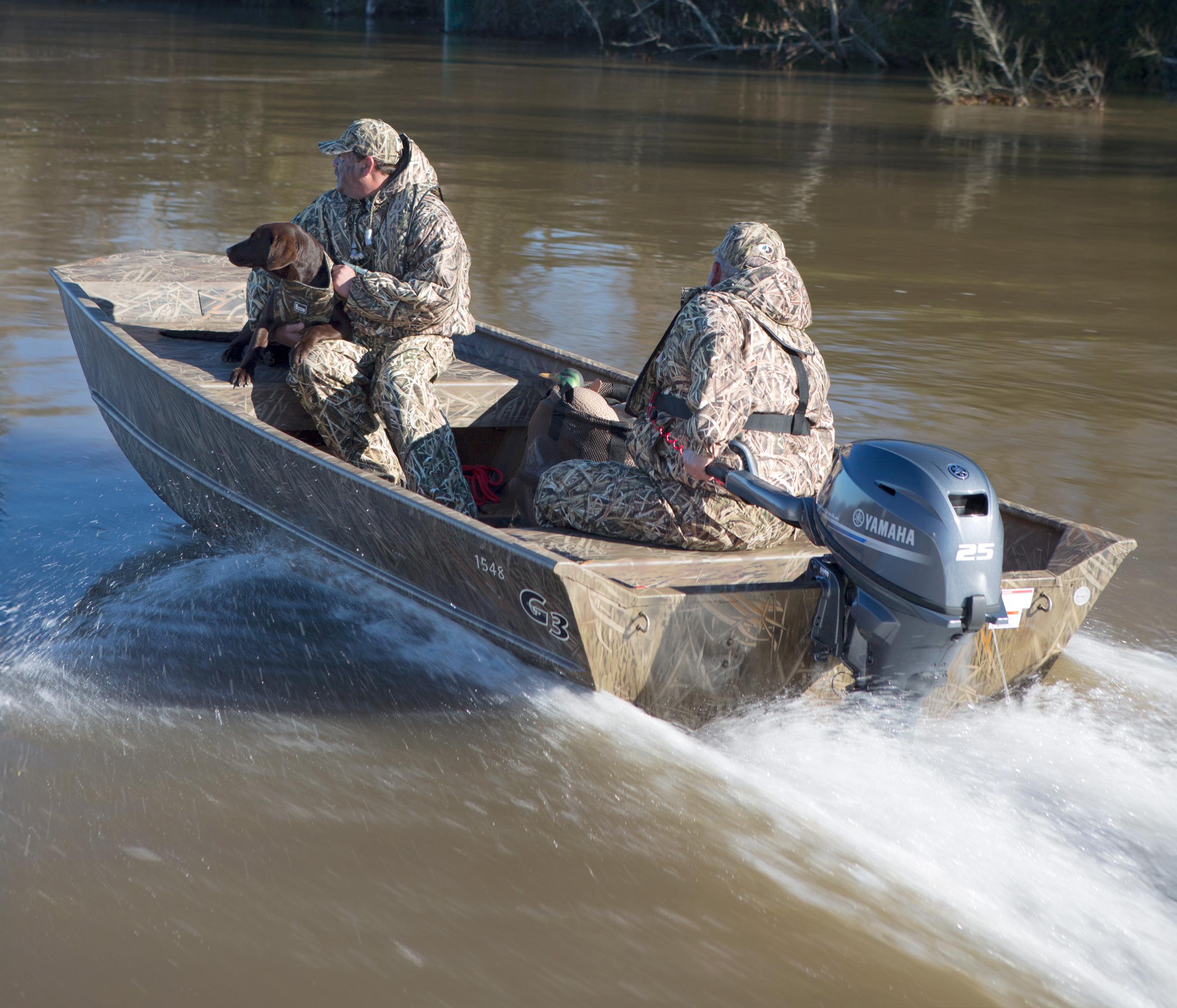
Additionally, the F50/ F60/ F70 models are now available in our most desired color by hunting and fishing enthusiasts, Matte Brown. Originally available for the F25 only, you can now have more horsepower as well as the perfect camouflage to enhance your outdoor experience.
NOTE: High thrust models are excluded.
Our most popular color, Pearlescent White, is now available for our F50, F70, F90, and (L)F115 models.
NOTE: High thrust models are excluded.
Helm Master EX Updates!
On the Helm Master EX autopilot panel, you no longer have to hold down “Track Point” in order to engage the feature. Now, just a quick hold will turn on Track Point. Cruise control for low-speed travel in canals and no wake zones is now easier with a short press of the “Joystick” button. This will enable the captain to move the handle forward to select a desired speed. The selected speed will be maintained until the captain pulls back the joystick.
For more information about these updates and products, look for the corresponding Hot Sheets in the Knowledge Center on YMBS.
WHAT’S NEW IN THE KNOWLEDGE CENTER!
The Knowledge Center is packed full of information that you can refer to while completing daily tasks. Simply use the keyword search to track down what you need. You can also browse through each category tab on the sidebar to see the different types of information provided. Here are some additions to the Knowledge Center that will hopefully continue to help you.
YMBS
OWNER’S AND SERVICE MANUALS
The following manuals have recently been uploaded to the Knowledge Center. To better service your customers’ outboards, you can search for the applicable manuals by inputting the LIT number or the model of the outboard motor into the search bar.
Owner’s Manual – F2.5 – LIT-18626-15-37
Owner’s Manual – F4/ F6 – LIT-18626-15-38
Owner’s Manual – F20 – LIT-18626-15-39
Owner’s Manual – F25/ T25 – LIT-18626-15-40
Owner’s Manual – F30/ F40 – LIT-18626-15-41
Service Manual – (MFG 2019-2025) F75B/F90B – LIT-18616-03-80
Service Manual – (MFG 2021-2025) VF90A – LIT-18616-04-14
HOT SHEETS
Hot Sheets are designed to give you specific details of Yamaha’s newest outboard products. From new colors to Helm Master EX updates, Hot Sheets provide you with the information you need when learning more about any new product.
Hot Sheets – New Styling + Colors
Hot Sheets – HARMO® 2.0
Hot Sheets – Steering Assisted Tiller Outboard Models
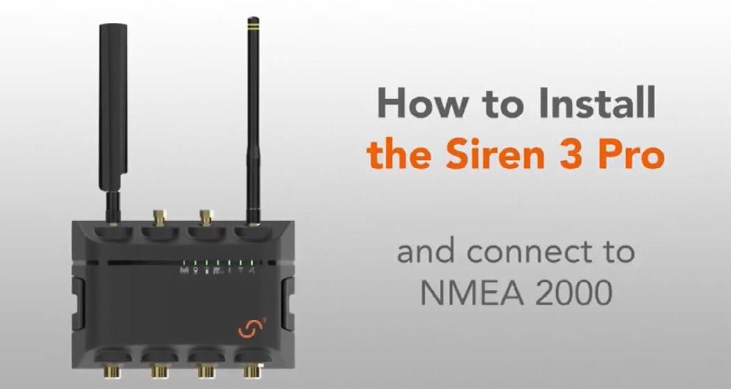
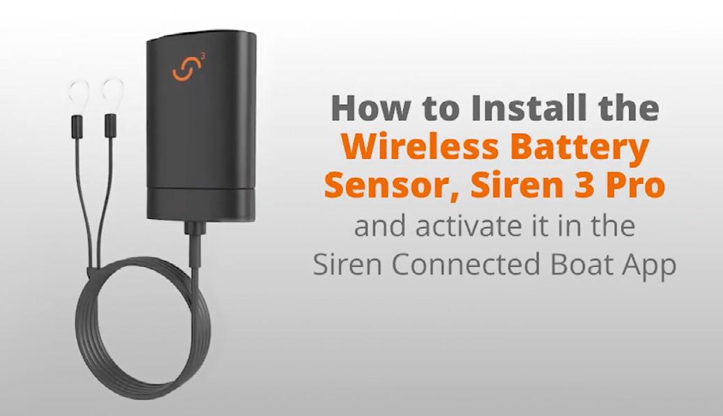
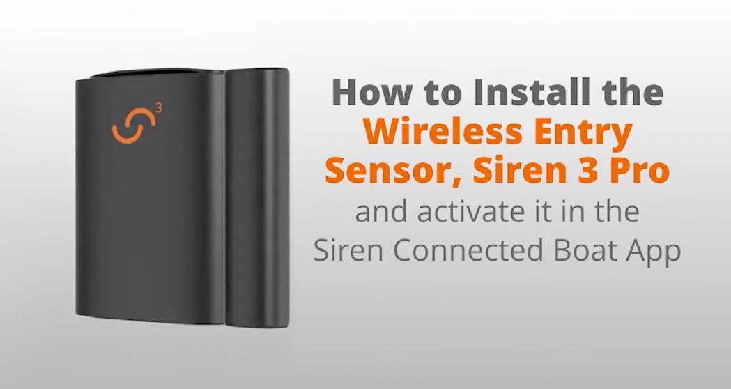
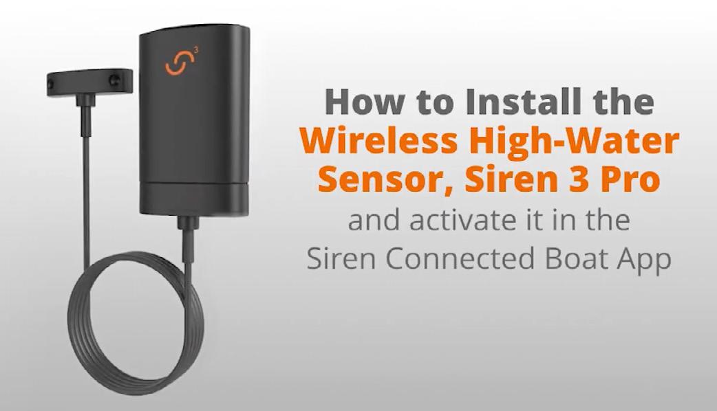
SIREN MARINE® INSTALLATION VIDEOS
These installation videos provide step-by-step instructions on how to properly install a Siren 3 Pro device as well as multiple sensors. Check out the videos by scanning the QR Codes below to learn more about how to complete these installation procedures.
Siren Marine – Installation Video – Battery Sensor
https://youtu.be/UDsggeENeys?si=mx7nci7p-OWfNOPI
Siren Marine – Installation Video – Siren 3
Pro Installation
https://youtu.be/K9cE1TPZXqA?si=-EAb07oMX7mX2Ny0
Siren Marine – Installation Video – High-Water Sensor
https://youtu.be/K_5x2Sq2GEg?si=EuJo0qSBYGapZQEx
Remember that the Knowledge Center can provide you with copious amounts of information that will make it easier to complete your daily tasks. If you need reference material when working on a customer’s outboard, be sure to check the Knowledge Center for whatever you might need.
Siren Marine – Installation Video – Entry Sensor
https://youtu.be/XVudqqrW3pQ?si=0A98GFh3Tnwhk67l
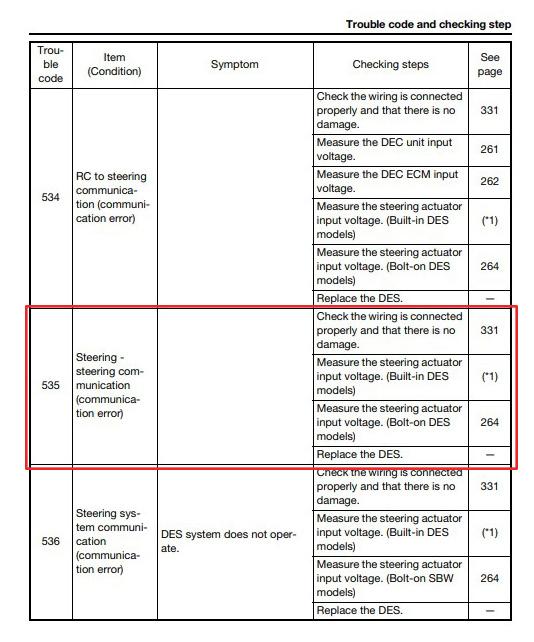
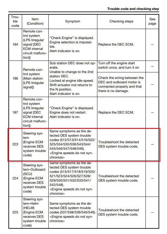
DIAGNOSING A 535 CODE ON A HELM MASTER EX SYSTEM
One question that our call center has been asked lately is, “How do I clear trouble code ‘535’ from my Helm Master EX system?” Whenever this trouble code pops up, the first and best method is to check and see if all of the components are connected and communicating properly on the CAN-bus.
NOTE: To refresh your knowledge on the CAN-bus, please refer to articles, “Identifying Yamaha CANbuses” (June 2023 On Board) and “Diagnostic Testing on Components and on the CAN-bus” (August 2023 On Board).
If you refer to the 2023 Helm Master EX 6X9 Digital Electronic Control Rigging Guide located in the Knowledge Center, you will be able to see a complete troubleshooting chart (beginning on page 251), with codes, symptoms, and diagnostic steps that will help you narrow down the cause of your system throwing this particular code.
However, some codes are accompanied in pairs, such as codes 535 and 223. Both of these trouble codes are telling you that there is a communication problem with the steering system.
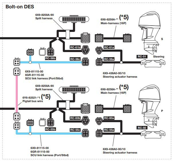
For the purposes of this article, we will use a diagram of a dual application for a bolt-on Digital Electric Steering (DES) system.
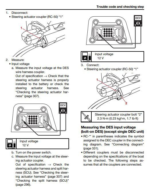
As you can see, both motors are connected on the same network. Now, if you have code 535 popping up on the meter, use the above-mentioned rigging guide on where and how to check the supply voltage, key-on power voltage, and ground at the steering actuator harness.
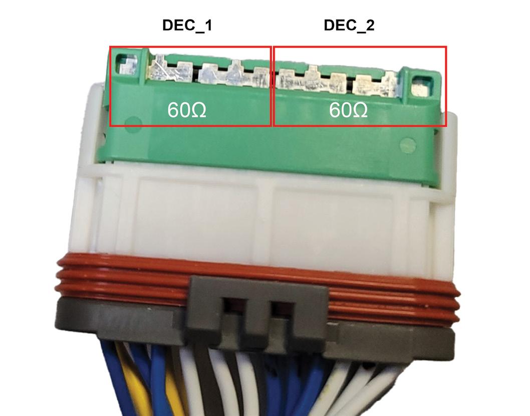
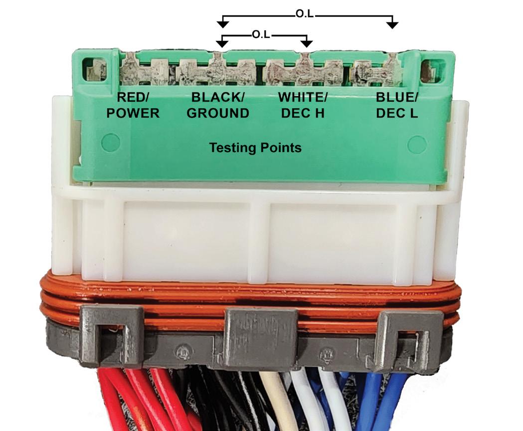
If no voltage is present on the steering actuator harness, that means the harness needs to be replaced or there is a bad connection between your measurement point and the battery terminals. If the voltage is reading correctly at that testing point, test the continuity between pins as stated in the “Diagnostic Testing on Components and on the CANbus” article mentioned earlier. Refer to the photos above right for testing points.
Keep in mind that code 535 is specific to the Steering Control Unit (SCU), so you will only need to test for correct voltage output between the SCU of each engine and the continuity of each harness between them. If all of the harnesses are reading the correct voltage and continuity is reading correctly on the CAN-bus, this is a strong indicator that one of the DES components needs to be replaced. Once you have treated the source of the problem and cleared the code, in this case code 535, all other associated codes, such as 223, will clear as well.
Remember, this troubleshooting method (for a communication issue like this) is common for any component on the CAN-bus on any network. In summary, test to see if the component that is experiencing a communication issue is receiving power. Then test to see if the component has good CAN H and CAN L continuity between the device that is missing from the network and the component that is reporting the communication error.
4.2L B MODEL TRIM SENSOR DESIGN
Addressing Issues with the Upper Tilt Ram Rod’s Roll Pin
By Jesse Dayton, District Service Manager
With the introduction of the XTO™ 5.6L V8 in 2018, a design change was made to how trim sensors operate. The design is very different from earlier models as it incorporates a three-wire trim sender that is keyed to the upper tilt ram pin—now retained by a roll pin.
When the engine is trimmed up or down, the outer part of the trim sensor, which is bolted to the swivel housing, rotates. The inner part of the trim sensor keyed to the upper tilt ram pin that is fixed in place does not rotate. This sensor works similarly to a throttle position sensor, where the sensor is fed a 5 V supply on the orange wire and, when there is a change in position, this causes a change in resistance that changes the output 5 V on the pink wire. This
output 5 V is received by the engine’s electronic control module (ECM), and it changes the reading on the trim gauge. This voltage can also be read with the Yamaha Diagnostic System (YDIS).
This design has now been incorporated into new models introduced since the XTO, such as the F150/200SA DEC/DES models and F150/200C mechanical control models, the 4.3L F350SA, and SHO® mechanical control and 4.2L B model offshore DEC and DES motors (VF200/ 225/ 250B, F225/ 250/ 300CB, F250/ 300SB).
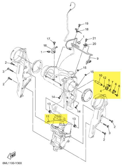
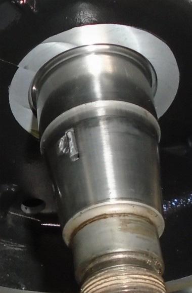
On the 4.2L B model offshore DEC and DES models and SHO mechanical control engines specifically, there have been reports that this roll pin (referred as a spring pin in PartsManager Pro™, reference #11 in the picture above) can partially or completely back out. When this happens, the upper tilt ram pin is no longer fixed in place, which can cause the pin to rotate on its own due to vibration, or the pin will move with the swivel housing. Both instances could result in incorrect trim sensor readings.
In situations where the trim reading is stuck in the up position, the engine may not have any trim up function. It may also activate the power trim and tilt protection feature which will put the engine in rpm reduction mode (see Info Exchange SP2024-002 for info on maximum rpm and trim sensor voltages where this feature will activate).
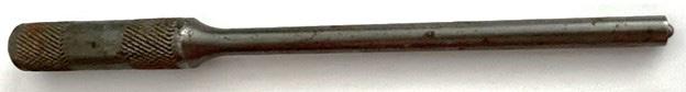
If the pin has partially or fully backed out, DO NOT REUSE THE PIN. Install a new pin (P/N: 91690-6002200) using a 6 mm roll pin punch (see picture below, acquire locally).
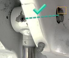
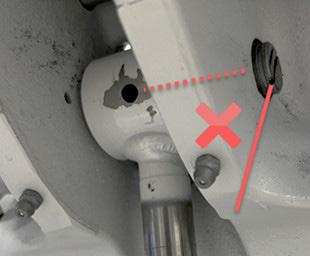
The upper tilt ram pin must be indexed properly to allow installation of the roll pin and for the trim
sensor to read correctly. There is a mark above the slot where a flat head screwdriver could be used to rotate the pin. This mark should be facing up as shown below.
While attending the Advanced Offshore instructorled training class, Wilmer Crawford of Legendary Marine in Panama City, FL, pointed out that the slot where a flat head screwdriver could be used to rotate the pin lines up perfectly with the hole that the roll pin gets driven into. Therefore, aligning the slot in the pin with the hole in the tilt ram is a quick and easy way to line everything up for the installation of the roll pin. Install the pin flush with the opening in the tilt ram (see pictures below).
For more information about the trim sensor, upper tilt ram pin, and roll pin, please reference the publications below. These publications are available electronically through the Knowledge Center found in the Yamaha Marine Business System (YMBS).
Log in to Yamaha Marine Business System (YMBS) > Knowledge Center > select Search Knowledge Center:
Info Exchange SP2024-002
Engine Service Manuals
• LIT-18616-04-35 – F350SA 4.3L V6
• LIT-18616-04-12 – VF200/225/250B 4.2L V6 SHO
• LIT-18616-04-05 – F250/300SB 4.2L V6 Offshore DES
• LIT-18616-04-06 – F225/250/300CB 4.2L V6
Offshore DEC
For specific warranty and technical assistance, contact the Dealer Support Call Center:
Live Chat: YMBS > Service Tab > Live Chat
Phone: (800) 353-5900 M–F 8:30 a.m. – 5:00 p.m. ET (closed 12:00 p.m. – 1:00 p.m. for lunch)
Email: mds@yamaha-motor.com
Technical Assistance Request (TAR): YMBS > Knowledge Center > Ask a Question
Removal and installation of the Power Trim & Tilt unit, including removal and installation of this roll pin and so much more is covered in the Advanced Offshore 4 ½ day Instructor-Led Training (ILT) class at our Marine Headquarters in Kennesaw, GA.
To register for classes, choose one of the following:
Register on-line: Yamaha Marine University (yamahalearning.com)
Call Yamaha Marine Training: (800) 854-4876 (option 3) or send an email to dealertraining@yamaha-motor.com
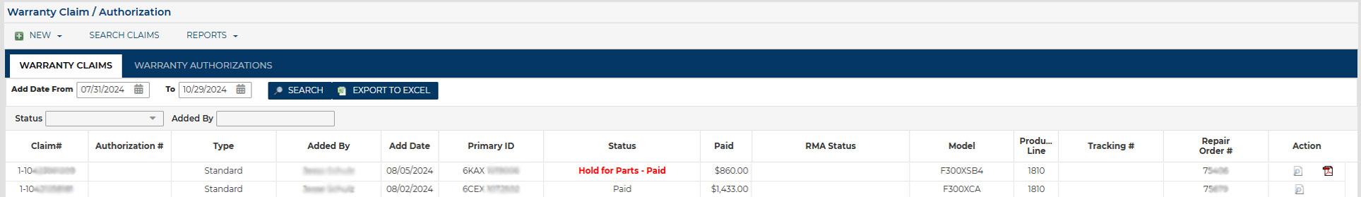
A NEW WARRANTY FEATURE ON YMBS
Yamaha is introducing a new warranty claim status, “Hold for Parts – Paid.” Yamaha will use this option from time to time to obtain parts on paid warranty claims when investigating trends or carrying out other market issue follow-ups. These paid-claim requests for parts to be returned to our Failure Analysis department will not affect the reimbursement you have already received for the warranty repair.
As a reminder, Yamaha warranty policies and procedures require all parts replaced to be held for 90 days from the date the claim is submitted, even after the claim is paid. Refer to Chapter 8 in the Outboard Warranty and Y.E.S. Handbook (P/N: LIT-11760-00-22), available printed or in the Knowledge Center in the “Warranty” category.
If you have submitted a warranty claim that was completed and paid within the 90-day period, you may still receive a message alert on the YMBS homepage as seen below.
Click on the alert to be taken to the “Warranty Claim / Authorization” page.
If the status is highlighted in red and set to “Hold for Parts – Paid,” then you should use the following procedure (which is the same as that for the regular “Hold for Parts” status claims):
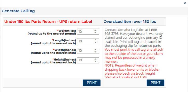
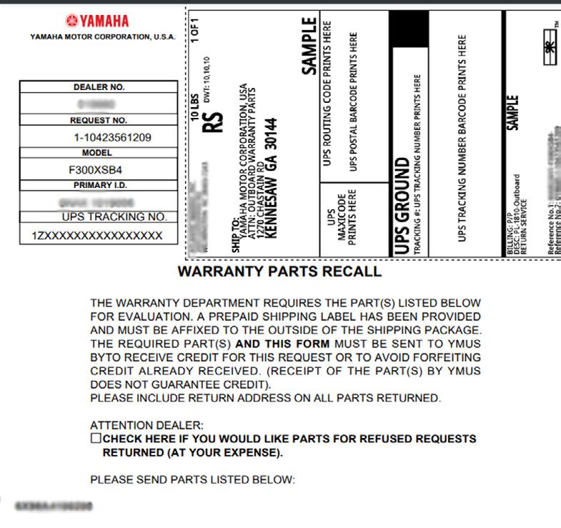
1. Click on the highlighted status to generate a Warranty Parts Recall form (“call tag”). Carefully check to see what part(s) are being requested on the form; we may only request one or two parts, not all the parts replaced.
2. Be sure each requested part is properly identified with a Warranty Parts Tag (P/N: LIT-11790-02-00) and pack the part or parts carefully to avoid damage during shipment.
3. Fill in the weight and dimensions of the package in the indicated fields and click “PRINT” to print out the form.
NOTE: You only have one chance to print, so be sure to specify the number of copies before printing. It is recommended to make at least two copies and keep one in your warranty files for the claim.
4. Cut out the return label portion of the form and securely tape it onto the package. Put the rest of the form inside the box with the part(s).
Thank you for using this procedure when requested. It will help Yamaha achieve its goal of maintaining and improving product quality.
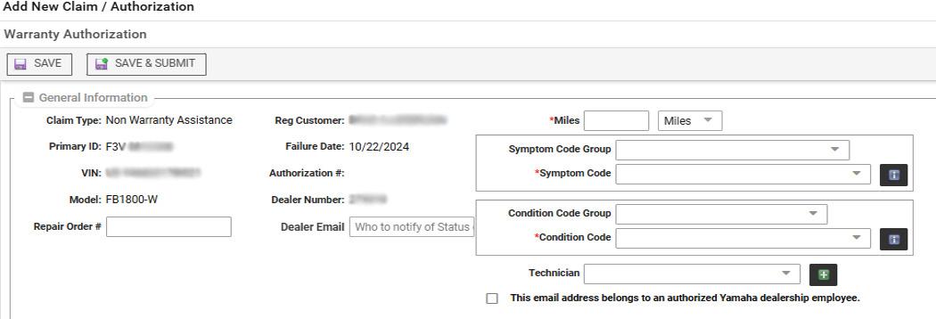
Remember, you can also have alerts about pending parts-return requests conveniently sent directly to your email so they won’t be missed. Simply insert your email address in the highlighted field below when filing your claim initially.
If you have any questions about this update, you can always call the Yamaha Warranty Support line (800) 353-5900.
Yamaha Marine University (YMU) Meets Yamaha Technical Academy (YTA)
We are pleased and excited to announce YTA as our global initiative to provide YMU’s quality of standardized learning for all Yamaha marine technicians. By continuing to develop this tailored curriculum, distributors have the opportunity to offer even more exceptional service and support to Yamaha customers worldwide while being at the forefront of marine technology.
Be sure to check out April’s issue of On Board for important information regarding the 2025-2026 program year.
These web-based training (WBT) courses are meant to supplement the instructor-led training (ILT) versions of the course, not replace them. Consider taking the online version of the course before arriving for the in-person course.
YTA Yamaha Diagnostic System (YDIS)
Method: Online, 5 modules
Master Tech Recertification: NO
Prerequisite: None
In this course, students will be introduced to the Yamaha Diagnostic System, the software and hardware requirements, the basic operation of YDIS, and optional accessories. With a combination of video and explanation of components, this course will help technicians navigate the YDIS system.
YTA Outboard Electrical
Method: Online, 6 modules
Master Tech Recertification: NO
Prerequisite: None
By the end of this course, students will have an understanding of electrical theory including AC/ DC, circuits, insulators, and semiconductors. Students will learn to use a digital multimeter, read wiring diagrams, understand the difference between relay, amp, and resistance testing. Students will also review Transistor Controlled Ignition (TCI), starting, and charging systems. Lastly, students will learn about the different components that make up the outboard electrical system.
YTA Engine Control
Method: Online, 7 modules
Master Tech Recertification: NO
Prerequisite: None
By the end of this course, students will have a comprehensive understanding of fuel injection models, their components, and how they are tested. Students will also gain knowledge about how these components work together, the flow of electricity in the system, and how virtual driving and digital electronic control play a role in engine control.
• Module 1: Introduction
• Module 2: Software and Hardware
• Module 3: Basic Operation
• Module 4: Accessories
• Module 5: Final Exam
• Module 1: Course Intro and Electrical Theory
• Module 2: Basic Circuit Testing and the Digital Multimeter
• Module 3: Direct Current Transistor Controlled Ignition
• Module 4: Starting and Charging Systems
• Module 5: Components
• Module 6: Final Exam
Scan the QR Code to enroll in YDIS.
• Module 1: Fuel Injection Model
• Module 2: Components and Testing
• Module 3: How it all Works Together
• Module 4: Flow of Electricity
• Module 5: Virtual Driving
Scan the QR Code to enroll in Outboard Electrical.
Scan the QR Code to enroll in Engine Control.
• Module 6: Digital Electronic Control
• Module 7: Final Exam
Officially featuring watercraft product information that will help dealers and technicians stay up-to-date on products and insight on how to successfully complete everyday service procedures!
TECH TIP CORNER!
1.8L & 1.9L SHEARED FLYWHEEL SYMPTOMS
Has your customer ever brought in their watercraft with any of the following symptoms?
• It will crank but will not run.
• There is no spark or fuel injection.
• It has a hard start or backfires.
If so, Evan Dobbins, Yamaha Testing Supervisor for Yamaha Boat and WaveRunner, advises that these symptoms could imply that the flywheel key has been damaged.
Has the engine been worked on recently? A sheared flywheel key is usually the result of the flywheel rotor not being torqued correctly during reassembly. It is important to have the applicable service manual nearby whenever working on a vessel, so you have the correct torque specifications right at your fingertips. These additional steps will help ensure that your customer’s product is being serviced with the utmost care.
Also, a sheared flywheel key could result from the customer revv ing the engine while out of the water to an excessive rpm. One example of when this can occur is if your customer takes their Yamaha Boat and WaveRunner out of the water and runs the engine over 4000 rpm or for more than 15 seconds while discharging any remaining water from the cooling water passages. Remind your customer to consult their owner’s manual for proper operating procedures.
DID YOU KNOW?
HYDROLOCKING
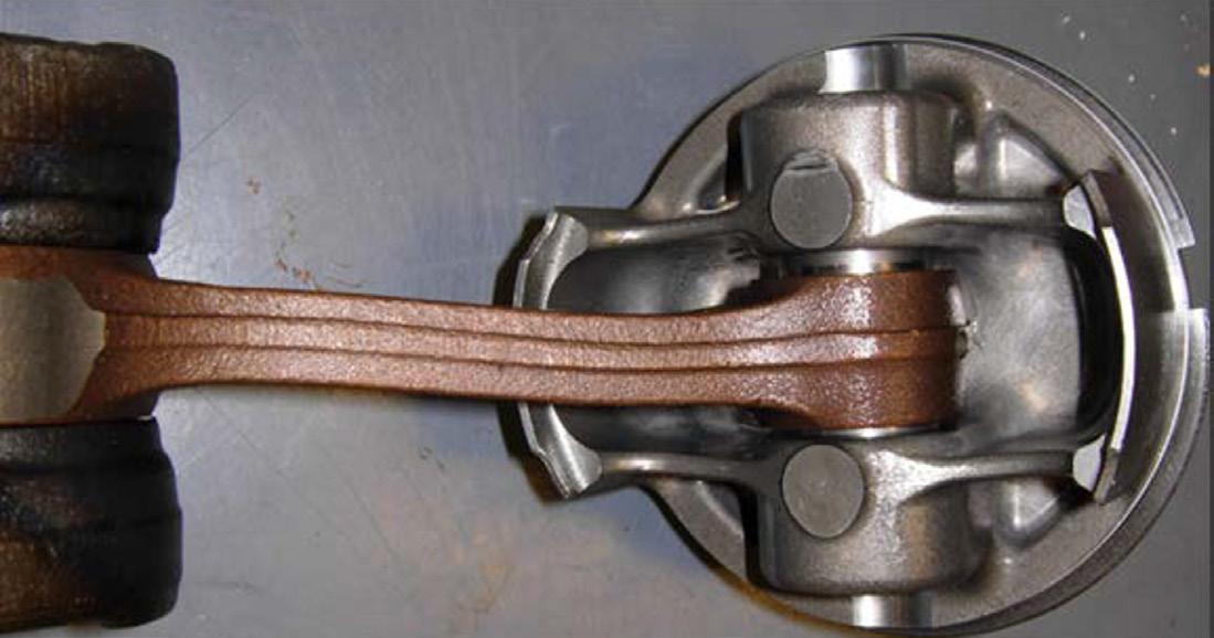
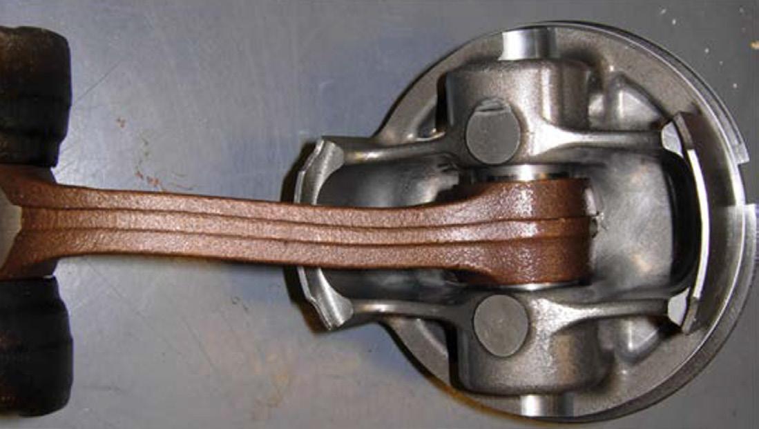
Did you know that a bent or broken connecting rod is usually caused by the engine hydrolocking? Hydrolocking is caused by too much fluid, water, or fuel entering the cylinder. Because fluid can’t compress like an air/fuel mixture, the piston cannot reach the top of the combustion chamber on the compression cycle. Either the engine stops rotating, or the connecting rod suffers damage. This can happen if an engine is submerged or takes on water. However, a leaky carburetor or fuel injector may fill the cylinder with fuel and hydrolock the engine as well. Although the connecting rod will bend at the time the engine hydrolocks, catastrophic engine failure may happen later if the engine continues to operate with a bent connecting rod.
As you can see, the connecting rod is bent, and the piston is disintegrated. Remember, you can inspect the oil, fuel, air filter, and the inside of the intake manifold for signs of water to determine if hydrolocking was the cause of a piston failure.
Below is another example of a hydrolocked engine.
PRODUCTS RINGING IN THE NEW YEAR WITH
Yamaha is pleased to announce the following products that will continue to ensure that our customers have the best possible onthe-water experience.
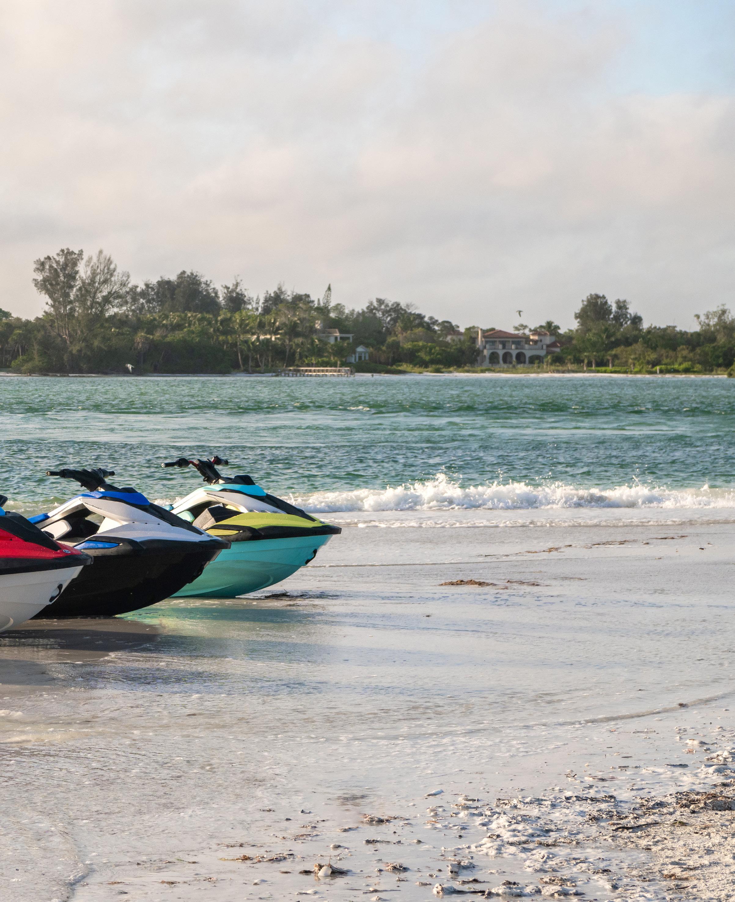
WAVERUNNER®
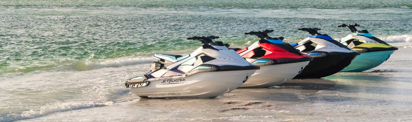
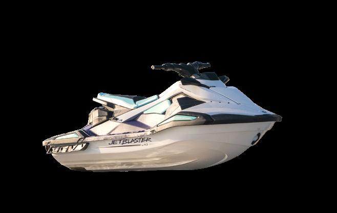
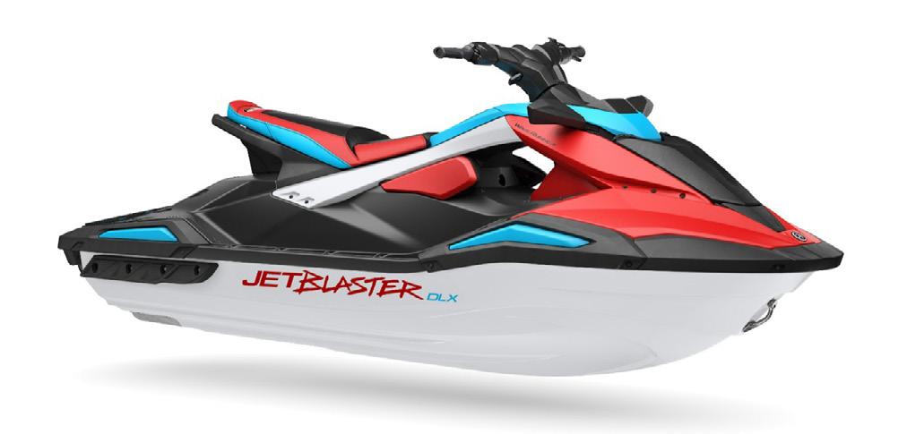
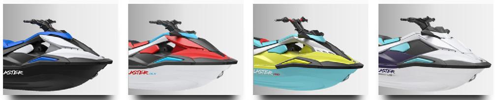
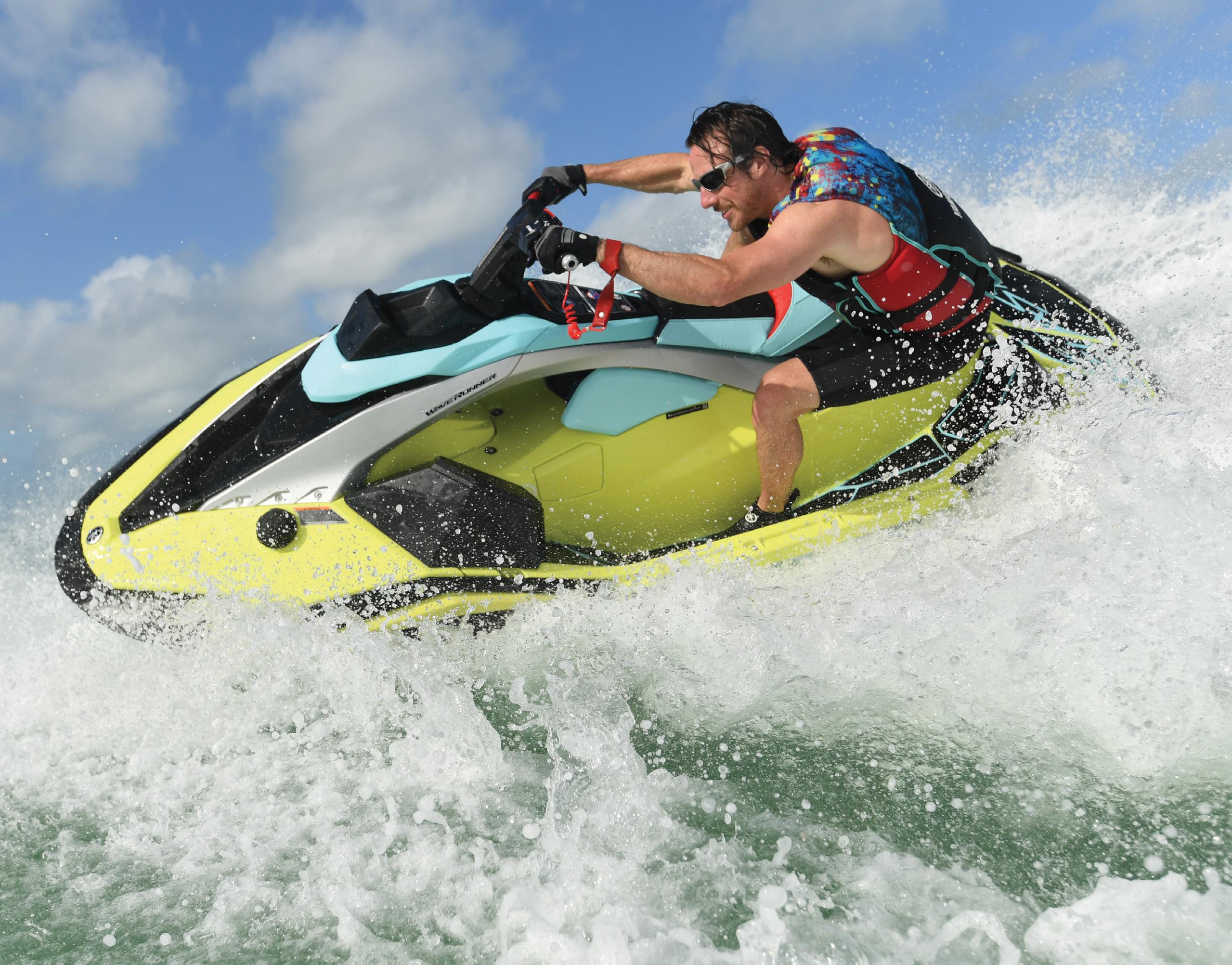
JETBLASTER SERIES
The modern style of our new JetBlaster series sports our award winning TR-1® engine and is equipped with Yamaha’s first polypropylene WaveRunner deck.
This series is available in four different designs in order to create the best outdoor experience, no matter how experienced or inexperienced the rider.
NOTE: DLX, PRO, and LTD models are equipped with RiDE® technology.
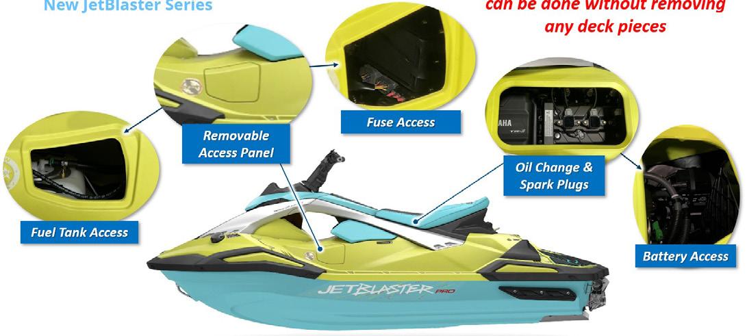
The removable three-part deck allows full access to the engine and other interior components when in-depth service is required (see page 28 in this issue for details). However, almost all regular maintenance can be completed without removing any of the deck pieces due to the increased number of access panels on the craft.
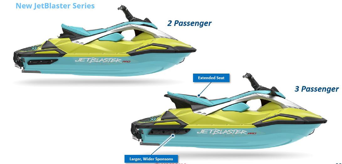
Additionally, the sharp angles and updated style have improved the comfort and performance of the ride, which will appeal to any customer looking to get into the watercraft lifestyle. Available in 2-up or 3-up seating options, the JetBlaster is perfect for a fun and exciting day on the water.
NOTE: The 3-up option is equipped with larger and wider sponsons than the 2-up option to increase stability due to the extra carrying capacity needed.
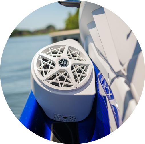
SOUND BY YAMAHA
The VX®, GP™, and FX® WaveRunner models are now equipped with the newly manufactured Yamaha audio system. This audio system is larger and more powerful than previous systems. No matter if your customer is going at a “no wake” speed or at high speeds and through splashing waves, the auto-volume feature ensures that the sound clarity and speaker performance stays consistent throughout the ride.
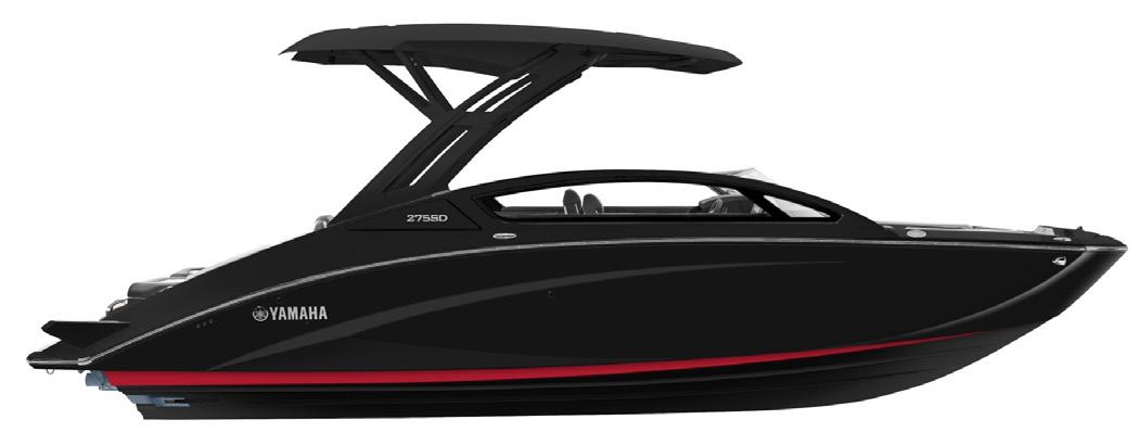
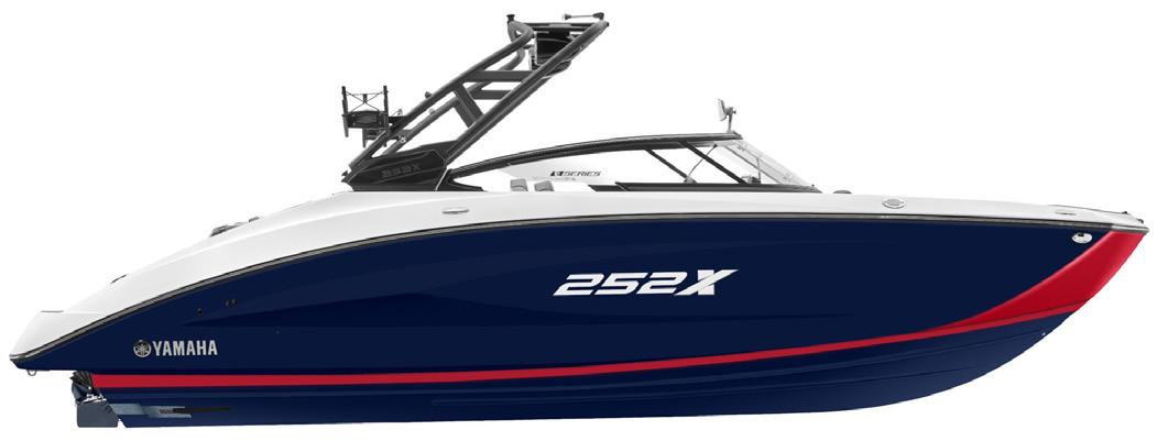
YAMAHA BOAT
NEW EXTERIOR COLOR OPTIONS!
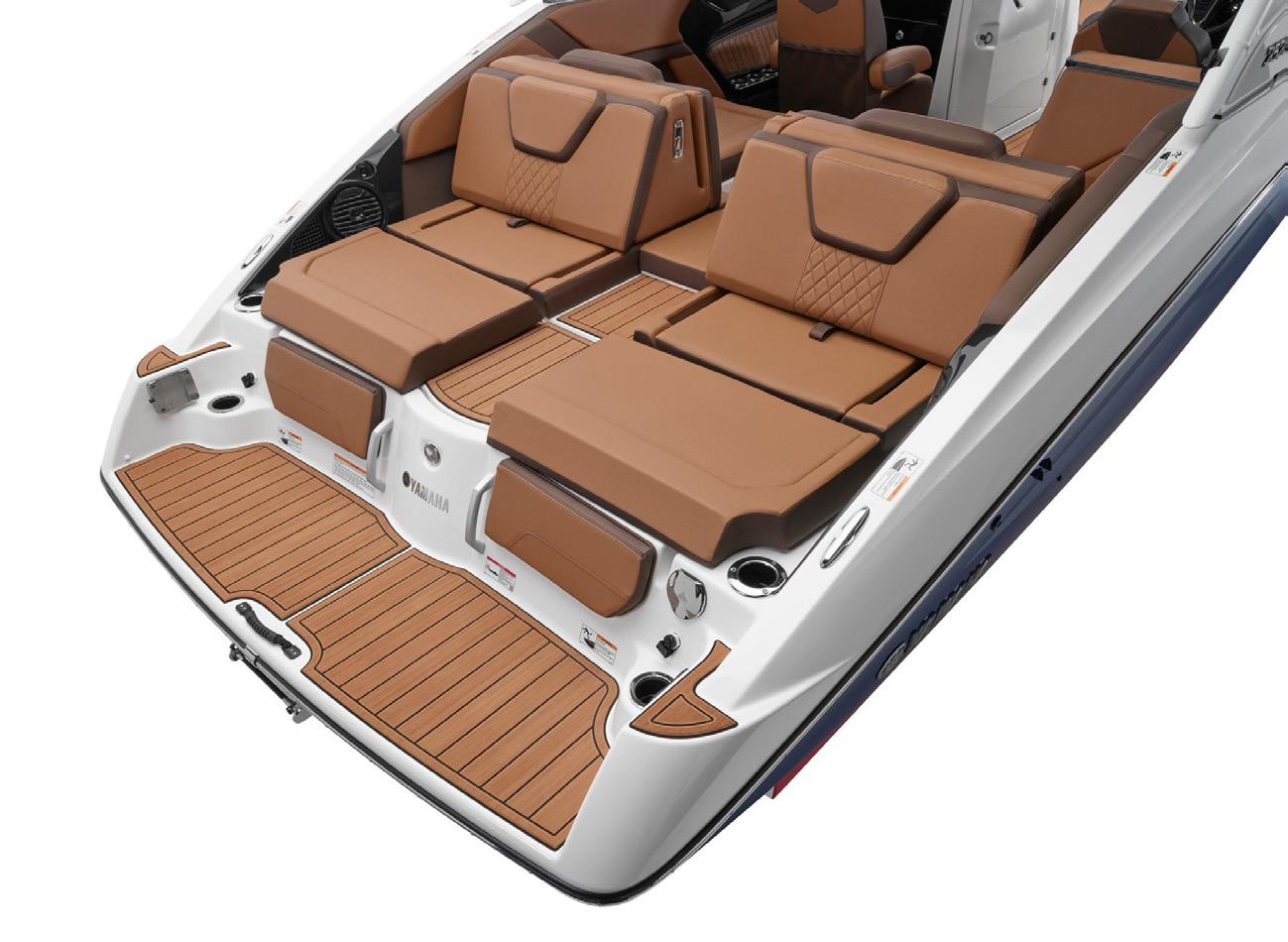
EXPANDED CHIL COOL TECHNOLOGY ® UPHOLSTERY
For 2025, our Boats not only have new exterior color options, but the 22', 25', and 27' model series have upgraded the standard factory interior with Chil Cool Technology® vinyl upholstery.
This upholstery consists of a highly advanced, and easy-to-clean material that is cooler to the touch after being in the sun all day than standard marine vinyl.
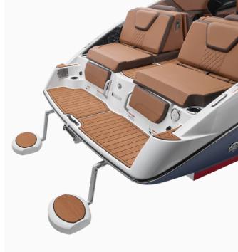
SWIM-UP SEAT BRACKETS
Now all 19' series boats (both FSH and Runabouts) will have the swim-up seat brackets already installed, with the exception of Wake Series models.
NOTE: Swim-up seats are not included as standard equipment and must be purchased separately.
These are just some highlights of the upgrades and improvements to Yamaha’s Watercraft product line, make sure to check out future issues of On Board for more information regarding other specific model upgrades for 2025.
Black
Yacht Blue
WHAT’S NEW IN THE KNOWLEDGE CENTER!
The Knowledge Center is packed full of information that you can refer to while completing daily tasks. Simply use the keyword search to track down what you need. You can also browse through each category tab on the sidebar to see the different types of information provided. Here are some additions to the Knowledge Center that will hopefully continue to help you.
YDS
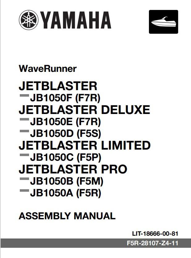
ASSEMBLY, OWNER’S, AND SERVICE MANUALS
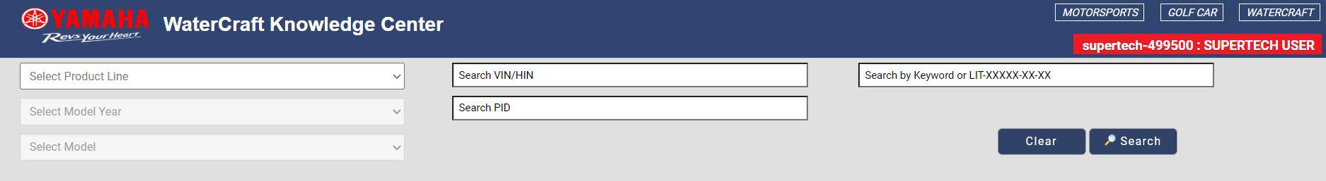
The following manuals have recently been uploaded to the Knowledge Center. To better service your customers’ watercraft, you can search for the applicable manuals by inputting the LIT number in the search bar or selecting the model of the watercraft from the drop-down menu.
Owner’s/ Operator’s Manual – GP SVHO – LIT-18626-15-22
Owner’s/ Operator’s Manual – GP HO – LIT-18626-15-23
Service Manual – 252 FSH Sport – LIT-18616-04-45
NOTE: RiDE Model and Supplementary Service Manuals contain updated service information for certain WaveRunner models. Make sure to also refer to these manuals if you are unable to locate specific information in the main applicable Service Manual.
TECHNICAL VIDEOS
Technical videos provide step-by-step instructions on topics such as how to update systems, accessory installation, and regular maintenance. Check out the videos by scanning the QR Codes below to learn more or even refresh your memory about how to complete certain procedures.
https://vimeo.com/1002071504/29ea15db34
Technical Videos – Removing the Fuel Pump – JetBlaster
Technical Videos – Removing the Steering Cable – JetBlaster
Technical Videos – Removing the Front Deck – JetBlaster
https://vimeo.com/1002070034/745bf72b7c
Technical Videos – Removing the Jet Pump – JetBlaster
https://vimeo.com/1002069520/71441e416a
https://vimeo.com/1002068168/5d2647698c
Remember that the Knowledge Center can provide you with copious amounts of information that will make it easier to complete your daily tasks. If you need reference material when working on a customer’s watercraft, be sure to check the Knowledge Center for whatever you might need.
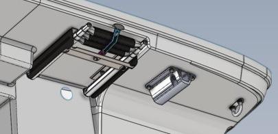
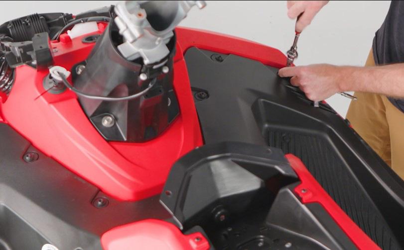
HOW TO REMOVE THE MIDDLE DECK ON A JETBLASTER
Yamaha’s new 2025 JetBlaster has a multi-piece deck assembly that is easy to remove and allows ample access to the engine, fuel tank, steering cable, and other components—although almost all regular maintenance can be completed without removing any of the deck pieces due to many access panels on the craft. However, when needed, for the purposes of this article, we will focus on how to remove the middle deck properly for complete access.
Tools required for this procedure are the following:
• 5 mm hex socket
• 4 mm hex socket
• 10 mm socket
• Flathead screwdriver
• 10 mm wrench
• 3/8" ratchet
• #2 cross tip screwdriver
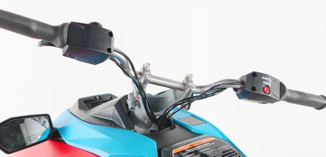
Steps to removing the middle deck: 1. Remove the handlebar covers.
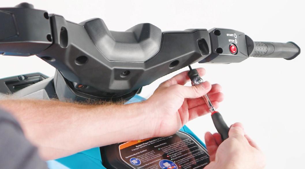
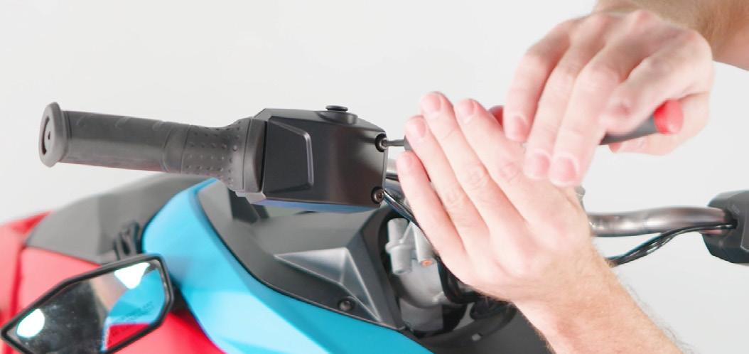
2. Remove the handlebar switches.
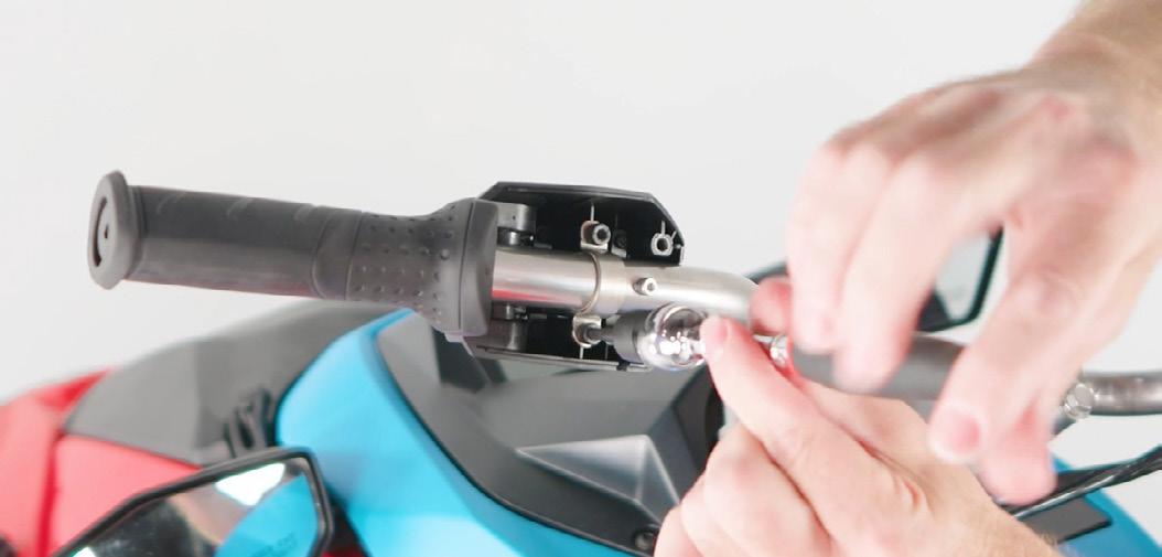
3. Remove the handlebars.
4. Remove the front storage lid and meter cover.
Reinstall torque spec: 5 Nm (0.5 m-kg, 3.7 lb-ft)
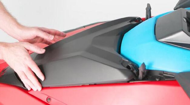
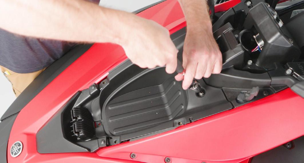
5. Remove the top cover by pulling upward to detach the fastening clips.
7. Remove the glove box plate.
Reinstall torque spec: 5 Nm (0.5 m-kg, 3.7 lb-ft)
6. Remove the front storage compartment. Reinstall torque spec: 5 Nm (0.5 m-kg, 3.7 lb-ft)
8. Remove the center rivet.
9. Remove the frame pieces.
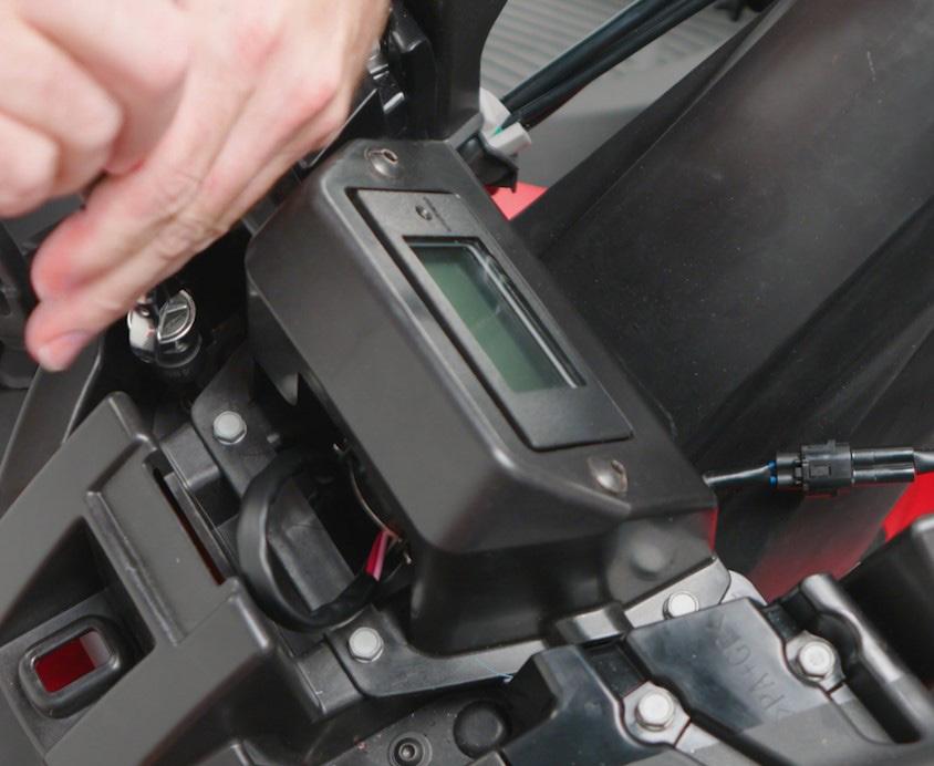
10. Disconnect the meter connections.
HOW TO REMOVE THE MIDDLE DECK ON A JETBLASTER
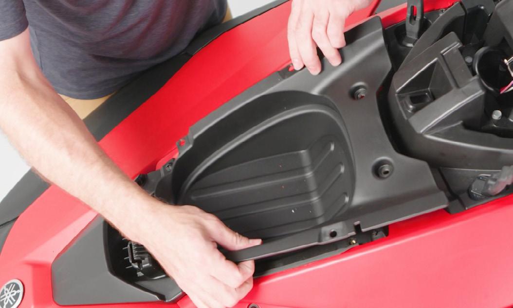
11. Remove the fasteners holding the center cover to the deck.
Reinstall torque spec: 5 Nm (0.5 m-kg, 3.7 lb-ft)
12. Remove the three fasteners holding the glove box assembly.
Reinstall torque spec: 5 Nm (0.5 m-kg, 3.7 lb-ft)
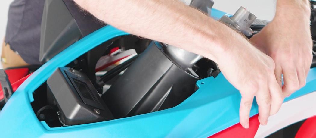
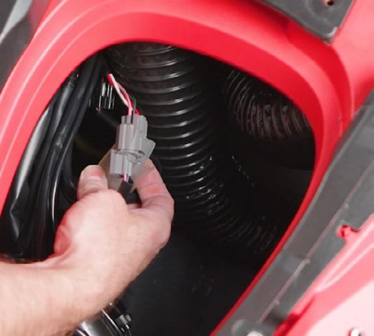
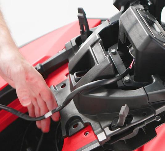
Guide the meter harness away from the top deck.
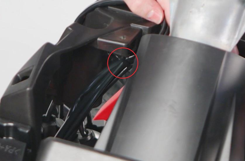
14. Cut the zip tie that holds the harness to the center cover.
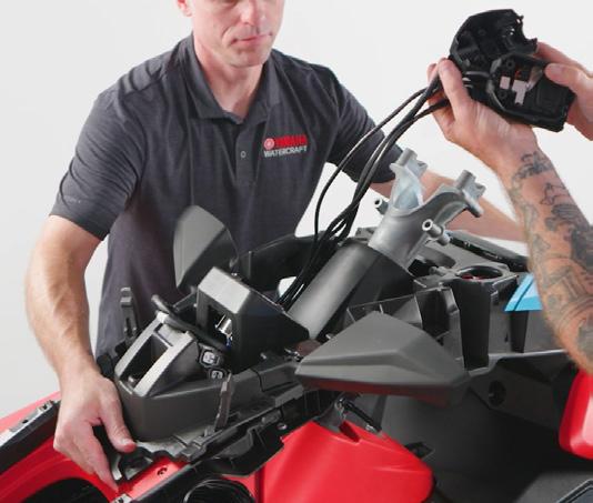
15. With help from an assistant, guide the handlebar switches through the center cover then remove it from the front deck.
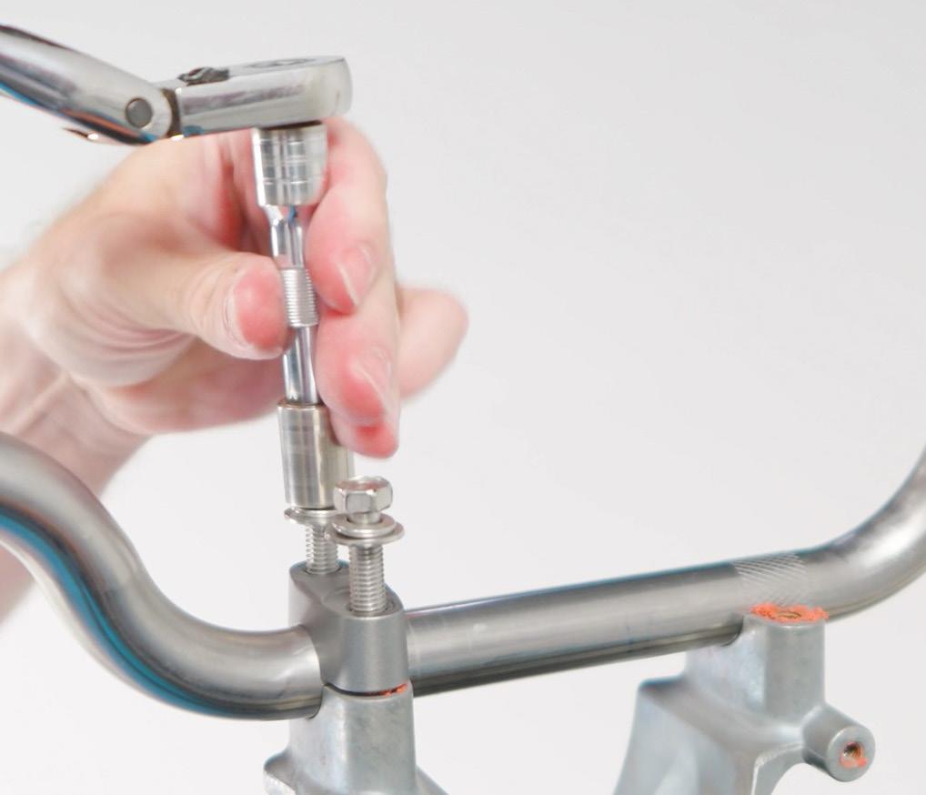
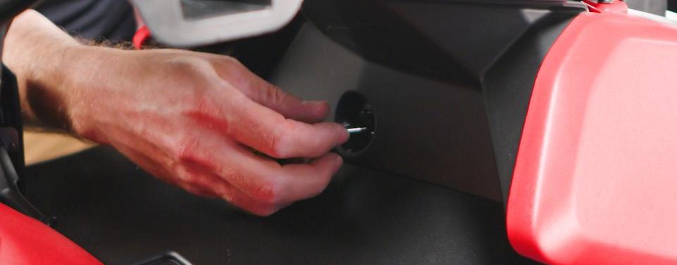
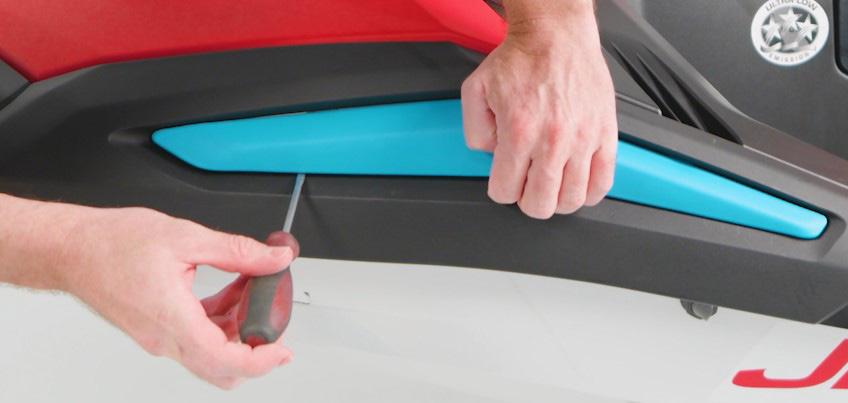
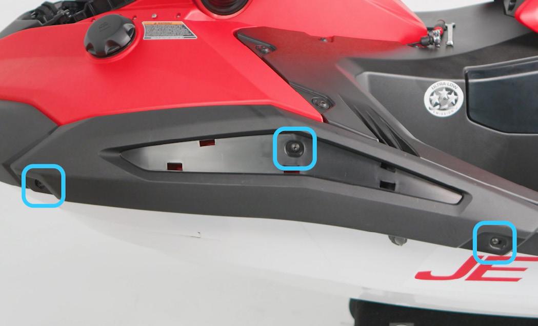
16. Use a small flathead screwdriver and gently pry up on the center trim piece to expose the hidden fasteners.
13.
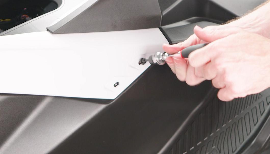
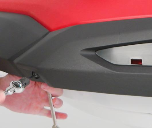
17. Remove the side gunwales.
Reinstall torque spec: 5 Nm (0.5 m-kg, 3.7 lb-ft)
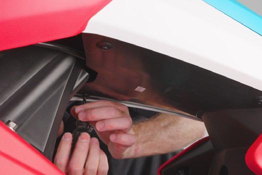
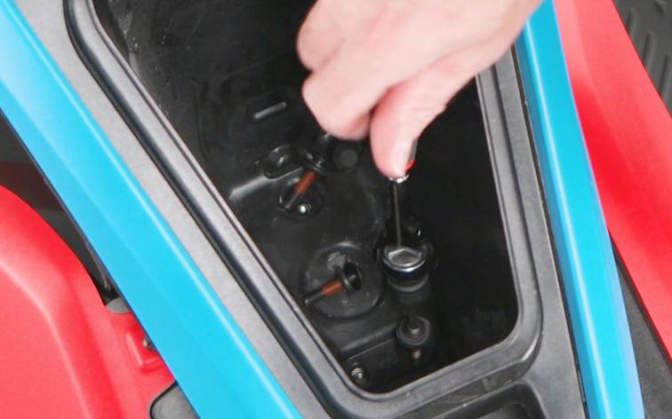
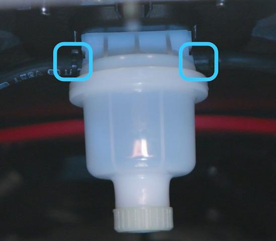
18. Disconnect the fuel tank vent hoses.
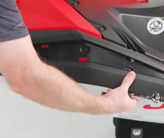
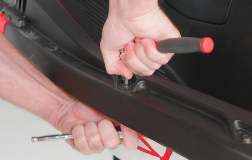
19. Remove the fasteners that surround the middle deck.
Reinstall torque spec: 7 Nm (0.7 m-kg, 5.2 lb-ft)
NOTE: The fasteners around the footwells are through-bolted.
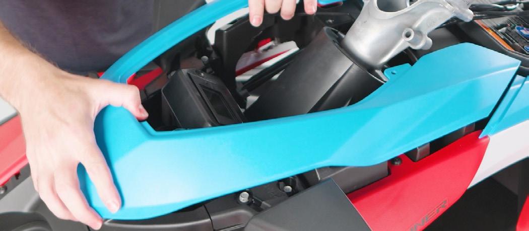
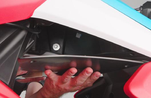
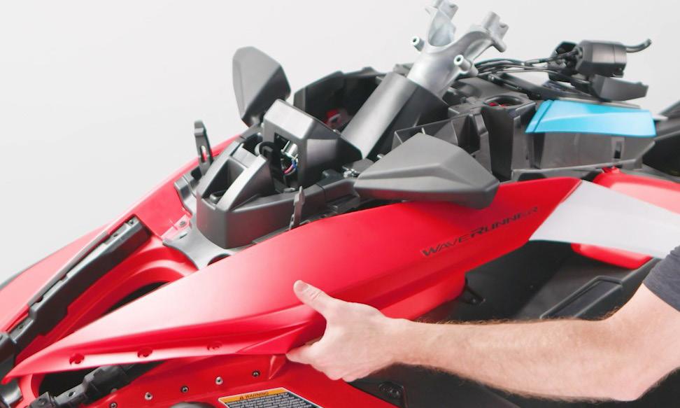
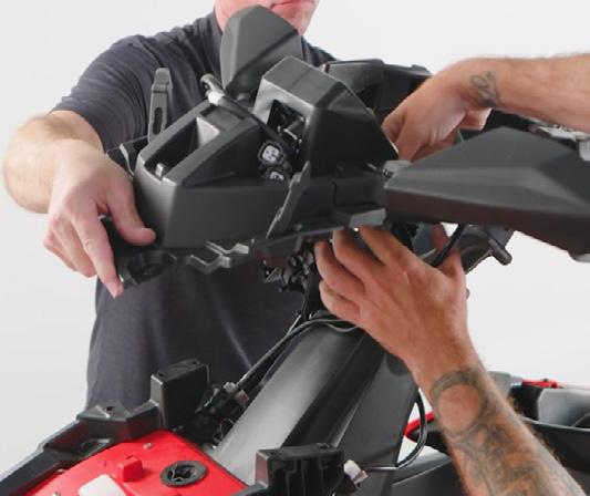
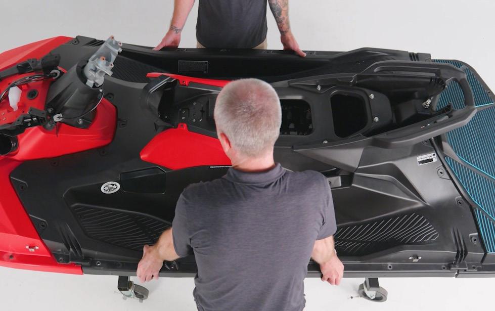
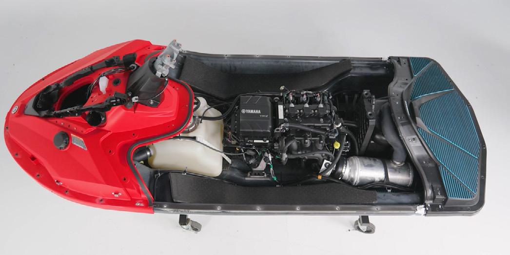
20. With help from an assistant, remove the middle deck assembly.
Now, you have ample room to service your customer’s JetBlaster. To view the video for this step-by-step procedure, scan the QR Code below or click the link. Happy wrenching!
https://vimeo.com/1002067486/d40b50ae5c
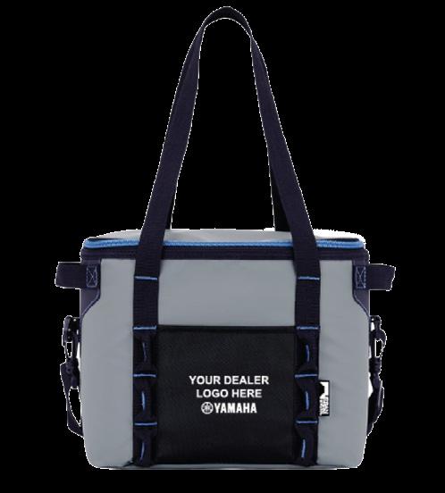
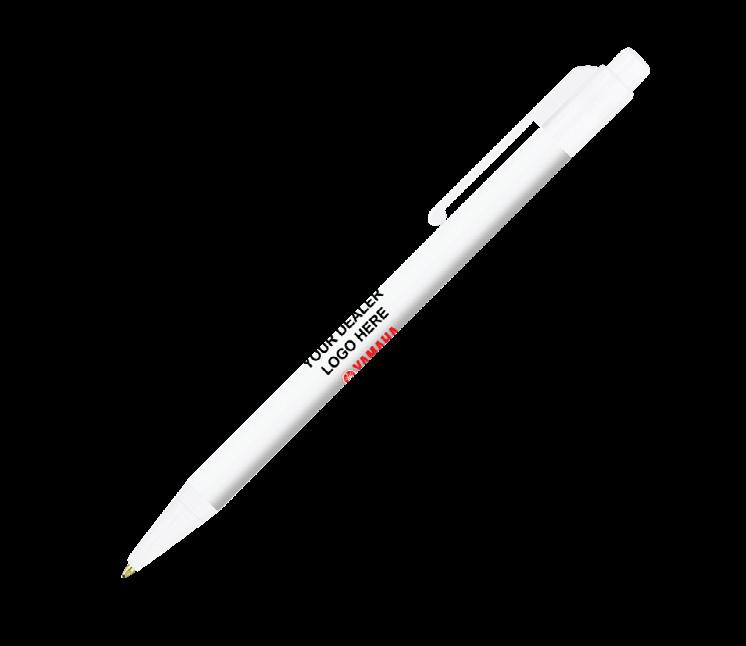
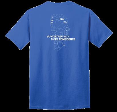
YAMAHA’S ONLINE
TECHNICIAN AND DEALER STORE
Motor
Get excited about this year’s events with all the essentials from our Yamaha Technician and Dealer store! No matter the occasion, stand out among the crowd with amazing give away co-branded items such as pens, canned drink coolers, coolers, and more. Also, if you are looking for a unique Yamaha giveaway, be sure to check out our newly designed Motor Line Drawing T-shirts that make the perfect door prizes or gifts.
Start shopping today at store.ymutechs.com. Please allow three weeks for processing and delivery of most items. Co-branded technician uniforms with the dealer’s logo can take up to six weeks. Scan the QR Code®* to go directly to the online store.
Have comments? Contact us! Please email comments to Marine_On_Board@yamaha-motor.com. When you subscribe to receive printed copies of On Board, we mail the magazine to the address you enter in your Tech Hub profile. If you need to update your mailing address to continue receiving your bi-monthly copy, it only takes a few minutes to make the changes. Please allow about one month for mailing changes to be implemented.
1. Click the Settings icon in the upper right corner of the screen. 2. Click Profile 3. Click Edit Profile on the right side of the screen. 4. Enter your mailing address in the Contact Information section.
5. Click Save in the upper right corner of the screen.