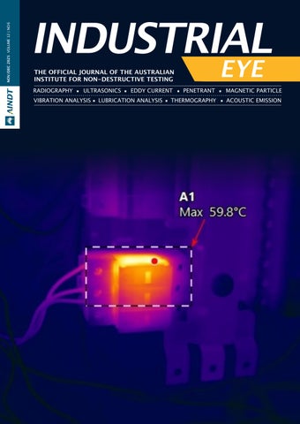
INDUSTRIAL
THE OFFICIAL JOURNAL OF THE AUSTRALIAN INSTITUTE FOR NON-DESTRUCTIVE TESTING
RADIOGRAPHY ULTRASONICS EDDY CURRENT PENETRANT MAGNETIC PARTICLE
VIBRATION ANALYSIS LUBRICATION ANALYSIS THERMOGRAPHY ACOUSTIC EMISSION


THE OFFICIAL JOURNAL OF THE AUSTRALIAN INSTITUTE FOR NON-DESTRUCTIVE TESTING
RADIOGRAPHY ULTRASONICS EDDY CURRENT PENETRANT MAGNETIC PARTICLE
VIBRATION ANALYSIS LUBRICATION ANALYSIS THERMOGRAPHY ACOUSTIC EMISSION
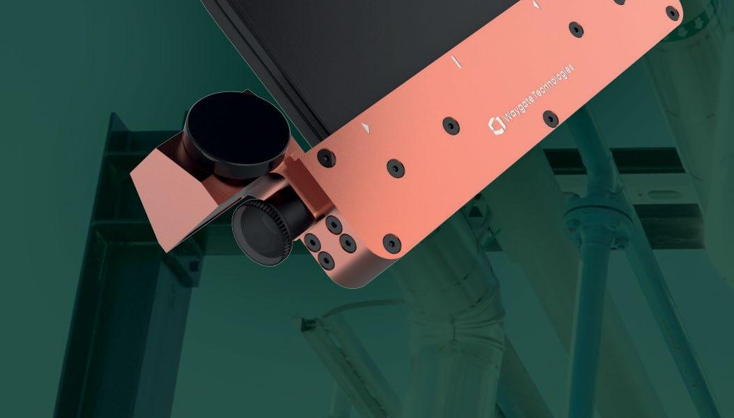
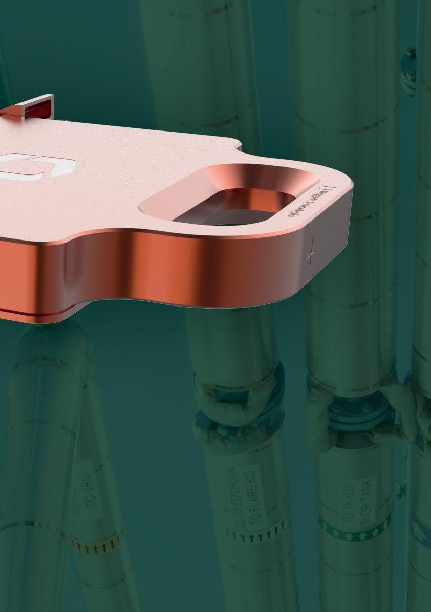
Dedicated to industrial use, this customer driven design of the next generation of DXR detectors combines image quality with rugged reliability, perfectly matching the criteria for the inspection of a wide range of weldments.
The new DXR Flex is a perfect fit for a wide range of weld related applications:
• pipeline weld inspection
• fabrication shop inspections (pipe spool, vessels, tanks, etc.)
• weld inspection (piping)
• crack detection


to know more? Scan this code or go to waygate-tech.com
Writing this first message as President is a huge privilege, and honestly, a humbling moment for me.

Writing this first message as President is a huge privilege, and honestly, a humbling moment for me.
First up, I want to acknowledge the massive shift put in by my predecessor, Josh Morris. Josh stepped back into the role during a tough time and has done the heavy lifting on the governance reviews and constitutional modernisation. He laid the groundwork for a more professional, robust Institute, and while that work is still ongoing, we are in a much stronger position today because of his leadership. On behalf of the Board and the members, thank you, Josh.
On a personal level, stepping into this role feels like coming full circle. I started my career in this industry as a trainee. I spent my first years on the tools, relying on the training and certification structures that this Institute supports, before moving into management and leading integrity contracts.
I share that because I want to make one thing clear: This Institute works. It builds careers. My main goal for this term is to make sure the next generation of technicians and practitioners sees the AINDT not just as a place to get a ticket, but as a partner for their whole career.
We all know the industry is shifting fast. Between the energy transition and new tech, the demands on us are changing. Clients don't just want "testing" or “monitoring” anymore, they want assurance. They want real answers that create value and help them make better business decisions.
My focus for this term is simple, ensure the AINDT stays relevant and valuable to you.
• We will keep backing the scheme committees to ensure our certification standards remain world class.
• Whether you’re a student, a tech, or a business owner, your membership needs to deliver tangible value.
• We need to be louder about the critical role NDT and CM play in Australia’s infrastructure and sovereign capability.
I’m lucky to be joined by a Board that brings over a century of combined industry experience and institutional knowledge.
These are leaders who know this Institute inside out and are committed to its future. I’m pleased to introduce the team for this term:
• Vice President: Ian Hogarth
• Treasurer: Damien Clarke
• Secretary: Peter Milligan
• Immediate Past President: Joshua Morris
Finally, a reminder that the AINDT belongs to you, the members. I don’t want to be a distant President. I’m always up for a chat about where we’re heading and how we can do better. I look forward to seeing many of you at the upcoming branch nights and the Summit. Let’s get to work.
Sam Hallifax President, AINDT Global SME & Business Improvement Manager, EnerMech

President:
President
Vice
Production Sally Wood Design Alarna O’Connell
AINDT
PO Box 52, Parkville Vic 3052
P: (03) 9486 9267
www.aindt.com.au
E: federaloffice@aindt.com.au
ADVERTISING
AINDT Federal Office
P: (03) 9486 9267
E: sally@wordly.com.au
Manuscripts should be submitted in electronic form:
1. in word
2. typed with single spacing
3. with figures as tif or jpeg files at better than 300dpi
Manuscripts should include:
1. symbols and abbreviations conforming to recognised standards; metric units (SI)
2. references listed, after the text, in the order in which they occur in the paper
3. references indicated in the text by arabic numerals in square brackets
4. tables and figures numbered separately but consecutively with Arabic numerals and brief, descriptive titles
5. a reference in the text to all tables and figures
6. graphs and diagrams made with lines of sufficient thickness to reproduce well
7. titles and address of authors
Procedure for submission of manuscripts:
1. articles should be sent to: journal@aindt.com.au
2. manuscripts will be submitted to referees who will remain anonymous
3. reprints of each paper will be supplied free to the author
Published by:
The Australian Institute for Non-Destructive Testing, PO Box 52, Parkville, Vic 3052 Australia
ISSN: 2203-2940

As we close out 2025 and I complete my second year at the Institute, I believe it’s a good time to reflect and see what we have achieved in the past 12 months. This year has been one of renewal, with new faces at all levels from the Board of Directors, Certification Board, Federal Council, Branch Councillors and Federal Office staff.
In 2024 the Institute’s focus was on reconnection, with our members, branches, partners, and the industries we serve following a period of disruption and change. In 2025 the Institute’s activities restored confidence and renewed personnel, operations and, most importantly, saw us gain ISO 9712:2021 accreditation. It was a year of engagement and reaffirming the value of belonging to a professional community that sets the benchmark for NDT practice.
Even prior to the implementation of the new standard, the Institute was on track for a record year of certification applications. We’ve seen encouraging growth in certification activity, recording a 60% increase over the past four years. Since the implementation of ISO 9712:2021 in September this trend has continued.
This increase in certifications demonstrates confidence in the integrity and independence of AINDT’s certification processes. Our commitment to maintaining the highest standards remains unwavering.
2025 has also been a pivotal year for governance. The AINDT Constitutional Committee continued its important work refining a modern, transparent, and representative structure for our organisation. This work is more than administrative. It’s about ensuring that AINDT remains fit-for-purpose in an evolving professional landscape.
Alongside this, we have strengthened our Board composition through the 2025 elections. With Sam Hallifax appointed as President, Ian Hogarth as VicePresident, Damien Clarke as Treasurer, and Peter Milligan as Honorary Secretary, the Institute benefits from a blend of experience, continuity, and new energy.
I extend my thanks to Josh Morris, who completed his term as President and continues to support the Board as Immediate Past-President. His leadership and commitment during a challenging period have left a lasting legacy.
In addition, Josh Wilkinson was elected as a Federal Council representative and has already shown he’ll be an asset liaising between the two bodies.
The AINDT Strategic Plan sets a clear direction for the Institute’s growth, relevance, and leadership over the coming years. Built around four key pillars — Certification, Membership, Education, and Advocacy — the plan focuses on strengthening AINDT’s core functions while positioning the organisation as the trusted authority in Non-Destructive Testing and Condition Monitoring.
AINDT will continue to uphold the highest standards of integrity and competence in certification. The focus is on maintaining compliance with ISO 9712:2021, improving examiner consistency, and ensuring the independence of assessments. Ongoing system improvements, documentation updates, and collaboration with Authorised Qualifying Bodies (AQBs) and training providers will reinforce quality assurance across all certification processes.
The Institute aims to rebuild and expand its membership base by increasing engagement, improving communication, and ensuring clear professional value for every member. Initiatives include revitalising branch activities, improving digital communication, and recognising the contributions of volunteers and professionals across the industry. AINDT seeks to provide members with stronger networking, learning, and recognition opportunities.
Education underpins the future of the profession. AINDT will work closely with training bodies, tertiary institutions, and industry partners to develop pathways that attract, train, and retain skilled professionals. This includes reviewing training standards, accrediting quality providers, and supporting lifelong learning aligned with certification requirements. The goal is to ensure that Australian practitioners remain globally recognised for their competence and professionalism.
As the national peak body, AINDT will strengthen its voice in representing the NDT and CM community. This includes engaging with government, defence, infrastructure, and energy sectors to highlight the importance of inspection, safety, and integrity. The Institute will contribute to standards development, influence national policy, and promote the profession’s role in sustainability, innovation, and advanced manufacturing.
In continuing the year of renewal, the NDT Certification Board (NDT CB) welcomed a significant number of new members from across a broad range of industry sectors (including aerospace, energy, infrastructure, and manufacturing), bringing with them fresh perspectives and deep technical expertise. This broadened representation ensures that the Board continues to reflect the full spectrum of Australia’s NDT community and the evolving needs of industry.
We were also pleased to welcome Mark Welland as the new Chair of the NDT CB. Mark’s extensive experience in inspection, quality assurance, and leadership will be invaluable as the Board continues to strengthen its
governance, enhance examination integrity, and oversee the implementation of ISO 9712:2021 across all levels of certification.
Under this refreshed leadership and expanded expertise, the NDT CB is well positioned to guide the future of professional competence and uphold the high standards expected of AINDT-certified practitioners.
None of these achievements would be possible without the dedication of our volunteers, Board members, branch committees, and Federal Office staff. To every member who has contributed their time, expertise, and enthusiasm this year — thank you. You embody the spirit of AINDT.
As we reflect on 2025, we do so with confidence and pride. Our Institute is not just surviving. It is evolving, reconnecting, and positioning itself for the future. The year ahead holds great promise, and together, we will continue to strengthen the reputation and reach of our profession.
Stuart Norman Chief Executive Officer, AINDT
The Australian Institute for Non-Destructive Testing (AINDT) held its 2025 Annual General Meeting (AGM) in Melbourne in November. Alongside the usual AGM proceedings, the results of the Board of Directors election were announced.
Following this, the newly elected Board met to determine Office Bearer positions for the forthcoming term.
AINDT is pleased to advise that Sam Hallifax has been elected President of AINDT. Sam has served on the Board for the past two years and has contributed significantly in his role as Secretary. We extend our congratulations to Sam and wish him every success in leading the Institute through his upcoming term.
With Josh Morris choosing not to re-nominate as President, he will now serve as Immediate Past President. On behalf of the Board, members, and staff, I sincerely thank Josh for the considerable time and commitment he has invested in guiding the Institute through a challenging period.
We also congratulate Ian Hogarth, who has been re-elected and will serve as Vice President.
The Board welcomes two familiar faces — Damien Clarke, who will take on the role of Treasurer, and Peter Milligan, who will serve as Honorary Secretary.
Not-for-profit organisations like AINDT rely on the dedication of volunteers who give their time and expertise to support the profession. I would like to express appreciation to Tom Hunt for his nomination and willingness to contribute to the Institute’s leadership.
Our thanks also go to Angelo Zaccari and Glen Haberl for their service on the Board over the past two years. Their efforts have provided valuable stability and direction during an important time for the Institute. Finally, during the Melbourne meetings, the Federal Council (FC) also convened, with Josh Wilkinson being elected as the FC non-voting representative to the Board of Directors.
On behalf of the entire AINDT community, we extend our congratulations and gratitude to all who continue to support the Institute’s mission.

Business Improvement Manager and Global Subject Matter Expert – Integrity, EnerMech
Sam is a seasoned leader with nearly two decades of experience in asset integrity. His career progression from roles in Quality Assurance to managing substantial multi-disciplinary contracts (NDT, scaffolding, remediation) led to his current strategic role as Business Improvement Manager APAC for EnerMech.
He also serves as the company’s Global Integrity Management Subject Matter Expert (SME), driving efficiency and best practice.
A dedicated AINDT member since 2006, Sam is a certified NDT Level 3 in four disciplines. His governance experience is reinforced by nearly ten years on the NATA Accreditation Advisory Committee.
Backed by extensive engineering studies and currently completing the specialism in strategy on an MBA, Sam possesses the unique blend of deep technical expertise and strategic acumen required to guide AINDT's growth.


Preparations are well underway for the AINDT Summit 2026, to be held in Newcastle, New South Wales, from 20–22 April 2026.
With around half of the exhibition booths already sold and a strong lineup of sponsors confirmed, momentum is building for what promises to be a standout event for the non-destructive testing (NDT) and condition monitoring (CM) community.
The Summit is designed to bring together key decisionmakers, senior professionals, and technicians from across the NDT and CM fields. Whether you’re a seasoned practitioner or looking to expand your technical knowledge, the program will deliver diverse opportunities for learning, collaboration, and professional growth.
While the educational component is central to the Summit, there will also be plenty of time to network and reconnect with peers. Between sessions, delegates can mingle at Newcastle Town Hall, explore the bustling exhibition space, or join one of several social events planned throughout the three days.
The event will officially commence with a Welcome Reception in the exhibition hall on the Sunday night. On Tuesday night, the Gala Dinner will celebrate excellence in our profession. For those eager to keep the celebrations going, a Gala Dinner After Party will follow at a nearby venue. Expect plenty of networking, music, and sponsor giveaways to carry the camaraderie well into the evening.
This year’s theme, The Power of Inspection, explores the concept of power both as a generative force— driving progress, energy and innovation—and as the detailed insight that inspection provides into the integrity and performance of critical assets. As part of the program, AINDT invites researchers, practitioners, and innovators to submit original papers showcasing new developments, technologies, or case studies that advance our industry’s understanding.
Delegates will receive a certificate of attendance reflecting professional development hours, which can assist with certification renewals or recertification requirements.
The AINDT Summit will once again bring together some of the most respected specialists in the field. This year’s expert presenters represent a diverse cross-section of industry, research and technology, offering valuable insights into the latest advancements shaping the future of NDT. Just some of our speakers include:
• Nick Ademo (Duerr NDT)
• Salah Attia (MCS)
• Nick Eleftheriou (Evident Australia)
• Jake Graham (Iris NDT)
• Chris Howson (QINDT)
• Brett Hyland (NATA)
• Fahad Mudayeq (SABIC)
• Nestor Sequera (SN Integrity)
• Khalid Sheltami (SABIC)
• Pranay Wadyalkar (OMS Software)
• Simon Wilding (Red Earth NDT)
David Bentley
Owner and Director, TICV
Title: Advanced NDT: Phased Array TFM A study of TFM and Compliance Weld Inspection
Total Focussing Method (TFM) has emerged in the last few years as a powerful evolution of Phased generate high – resolution, Array, offering full-matrix capture (FMC) data acquisition and advanced processing techniques to generate high resolution, true to geometry images of flaws .Whilst its benefits in terms of sensitivity, defect characterisation, and coverage are clear, the integration of TFM into code compliant inspection remains an area of ongoing development. Knowledge of the different available equipment is quite limited in general terms so this will also be looked at from a practical perspective in this presentation.
The misunderstandings that occur due to lack of available training lead (TFM Specific) to incorrect site inspections that are non-compliant and can be misleading. This presentation will be based on practical inspection of a series of samples with implanted and natural weld flaws in plate and pipe and includes several Austenitic samples. The methodology will be based on ISO 23864, ISO 23865 and ISO 22825.

Sam Cunningham Group Sales Manager, Lavender International NDT Vice President, British Institute of Non-Destructive Testing
Title: Closing the Skills Gap: How the UK NDT Apprenticeship Model is Rebuilding the Workforce
Over the last decade, the UK has taken bold steps to tackle one of the biggest challenges in the NonDestructive Testing sector, a widening skills gap caused by an ageing workforce, a lack of new entrants, and an urgent need for consistent, high-quality training.
In response, a national NDT Apprenticeship program was developed and rolled out, backed by industry, government, and training providers.
The results speak for themselves: over 300 apprentices have now completed the program, with the majority achieving a minimum of three PCN Level 2 certifications across methods including ultrasonic, magnetic particle, penetrant and visual testing.
A further 140+ apprentices are currently active across two approved standards: the NDT Operator and the Non-Destructive Testing Technician.
This presentation will explore how the UK’s approach has helped close the skills gap, rebuild the talent pipeline, and inject much-needed youth, diversity, and structure into a profession often seen as niche and difficult to access.
Early bird registration is now open, offering significant savings for those who book early. To secure your place, visit the Summit website: aindtevents.eventsair.com/aindtsummit-2025/register
Join us in Newcastle this April to celebrate The Power of Inspection—three days of innovation, insight, and industry connection that you won’t want to miss.


The AINDT Federal Council met in Melbourne on 18 November 2025, as part of the proceedings associated with the 58th Annual General Meeting of the AINDT.

The meeting included a review of membership strategies, and it was agreed that greater focus should be placed on enhancing engagement and delivering increased value for existing members.
This report outlines the key decisions, initiatives, and next steps to strengthen member involvement and satisfaction.
AINDT has continued to review benefits for its members. However, the Federal Council believes that quality engagement and professional value are more critical to sustaining long-term membership and advancing the NDT and Condition Monitoring profession.
Key Outcomes from the Federal Council Meeting
1. Engagement Priorities
• Improve digital platforms for easier access to resources and certification information.
• Increase interactive events and networking opportunities at state branch level.
• Expand professional development offerings, including webinars, technical papers, and certification support.
2. Governance Enhancements
• AINDT Strategic Priorities – Certification, Education, Membership and Advocacy.
• Maintain the federal model with strong state branch representation.
• Review governance frameworks for transparency and compliance.
3. Volunteer Support
• Develop clearer policies and recognition programs for volunteers to encourage participation.
• Improved engagement with current branch members and take the examples provided by our WA branch colleagues.
Upcoming Initiatives
• Launch a member survey with state branches to measure engagement and satisfaction.
• Prepare for AINDT Summit 2026 conference with strong member involvement.
• Develop a AINDT timeline for events and online resources.
• Strengthen Federal and branch-level communication to ensure consistent messaging and support.
The Federal Council’s decision marks a significant step toward building a more connected and engaged AINDT community. Your involvement as a current AINDT member will promote active participation across the NDT and CM communities.
December 2025
The AINDT is a national peak body that promotes the professional practices of non-destructive testing and condition monitoring personnel. Our mission is to provide members, industry and the community with independent and professional service in relation to the science and practice of non-destructive testing.
Through the work of our state branches and federal office, AINDT is committed to fostering a community of professionals and organisations dedicated to the fields of non-destructive testing, engineering, and materials and quality testing.
We offer a tiered membership structure, inviting businesses to enhance their professional standing and industry influence by becoming a Company, Corporate, or Sustaining member. Our memberships unlock a suite of benefits, including marketing opportunities, heightened support, streamlined staff certification management, and much more. AINDT would like to thank the companies below for their valued support.
ATTAR
D R May Inspections
EnerMech
SRG Industrial Pty Ltd
Intertek
SUPPORTING MEMBERS
Chevron
COMPANY MEMBERS
NSW
AXT Pty Ltd
Bluescope Steel (Port Kembla)
ENDETEK
HVT Inspection Services
NBQC and Inspection Services
NDT Equipment Sales Pty Ltd
Noble Engineering Services
Reliance Hexham
RPG Australia
Russell Fraser Sales Pty Ltd
Simplifi Nii P/L
SmartChem Industries Pty Ltd
Sonix NDT Pty Ltd
Thermal Imaging Services (AUS)
QLD
AXS Pty Ltd (Mackay)
Australian Biosecurity Services
Pty Ltd
Industrial Mining Inspection
Solutions
Azure NDT Quality Services Pty Ltd
Bureau Veritas Australia
Chemetall (Australasia) Pty Ltd
Evident Australia Pty Ltd
GFS NDT
Hofco Oilfield Services
IRISNDT
OMS Engineering Pty Ltd
SafeRad SE Asia Pty Ltd
School of Engineering
TR Pty Ltd
International Tube Testing Pty Ltd
Metal Testing Pty Ltd
M-Test Mackay Pty Ltd
Queensland Alumina Limited
Testing Inspection and Calibration Services
ATCL
Defence Science and Techology Organisation (DSTO – Fishermans Bend)
Gippsland NDT Services Pty Ltd
Global Inspections & Engineering
Services Pty Ltd
ITest NDT
Iron Training and Consulting
LMATS Pty Ltd (Williamstown)
NATA
OMS Software Pty Ltd
Stocks and Partners Ltd
SA / NT
ASC Pty Ltd
Kuzer Technical
QMS
Red Earth NDT Pty Ltd
WA
Alliance Solutions Group
Applecross Electrical and Testing Services
Asset Reliability Inspections Pty Ltd
Assurity NDT & Consulting
GoldFields NDT
ICM Training Solutions
MJ Engineering Inspection
Services (Welshpool)
J & S Castlehow Electricial Services
Vertech
Weld Integrity
Wood – Asset Performance
Optimisation
With 2025 wrapping up, the AINDT NDT Certification Board met for the last time for 2025 with a face-to-face meeting held in Melbourne on 18 November. The meeting was well attended and the full agenda was covered.

A key focus of the meeting was bringing together the new members of the NDT Certification Board. Several fruitful conversations were had over the course of the day on wide ranging topics including the future of NDT and the development of future NDT technicians.
Several projects for 2026 were discussed, including the modernisation of the online portal. In the meantime, the system remains a hybrid of an online portal augmented by forms. The portal is a means to register your application with the AINDT and to collect the basic detail for the application. Upon completion of the online portion of the application, the Federal Office emails applicants forms to fill in to complete their application. These forms are required to meet the requirements of ISO 9712: 2021 as the portal is currently unable to fully accommodate this. This is a key focus for 2026: to develop an intuitive and seamless process for all applications into the future.
The Federal Office and the Applications Committee have been kept very busy this year with a standout year for the sheer number of certifications processed.
Over the past three months, a rising number of applications under review have been found to contain major inconsistencies. For instance, one candidate
claimed 37 hours of experience within a 24-hour period. In the future, referees and Level 3s will be held to accountable for false claims on applications.
The Pannel of Examiners had a busy year, with meetings held monthly in each of the Method subcommittees, reviewing exam question and conducting examination performance reviews. Of the initial 18 members, we are down to 14 core members that put in month in and month out. Thank you all for the sustained efforts.
As such, I would like to ask if there are any current AINDT Level 3s who would like to volunteer for a position on the Pannel of Examiners for 2026. If you feel like you would like to get involved, please apply via email to The Chaiman of the Panel of Examiners with a short cover letter and brief CV to chiefexaminer@aindt. com.au. Applications close on 31 December.
From all on the AINDT Certification Board, we wish all members and certificate holders a happy and safe Christmas period and prosperous New Year for 2026. I look forward to launching into a exciting 2026.
Regards,
Mark Welland Chair, AINDT NDT Certification Board
The Condition Monitoring (CM) Certification Board met in Melbourne on 18 November 2025, as part of the proceedings associated with the 58th Annual General Meeting of the AINDT.

There are several key areas of work for the CM Certification Board to complete over the next 12 months. This includes revising and publishing an updated Certification Guide, as well as providing clearer direction on matters related to recertification. The priorities for 2026 include:
1. Clarifying the Certification Guide regarding the transfer of certifications from other certification bodies.
2. Providing greater clarity in specific sections of the Certification Guide where ambiguity currently exists.
3. Continuing development and refinement of the examination database.
4. Implementing online examinations.
In relation to certification transfers, the CMCB board will accept transfer of certifications from other certification bodies who are JAS-ANZ Certified Bodies for all methods. No examination will be required of applicants. To be eligible, the certification being transferred must be current, valid and not expired. Applicants must submit a completed application form, evidence of their
existing certification, and proof of ongoing work in the applicable method. The AINDT certification will be issued with the same expiration date as the transferred certification.
The CMCB board has decided to remove the need to apply for recertification at the 10 year renewal stage. At the five year revalidation period, an application will need to be submitted for consideration. The revalidation process will simply require evidence of continuing training and practise in the method being applied for in order for the renewal to be issued.
The work of the CM Certification Board continues to focus on further improvements and development of the certification scheme. The work of our volunteers is generous and high quality. Without the quality of the persons volunteering on the Board, the success of the scheme simply would not be what it is today.
The Board looks forward to 2026 as a year of meaningful improvements and significant developments across the certification scheme.
Shawn Moore Chair, AINDT CM Certification
Board
Unlock the future of your career with top-tier condition monitoring training from trusted providers.
These training centres have earned the endorsement of AINDT, aligning perfectly with the national syllabi approved by the AINDT Certification Board. This ensures that you receive the highest standard of education and training.
To maximise your learning experience, AINDT recommends obtaining a copy of the training module—either directly from the training provider or by downloading it from the AINDT website. This will ensure you are well-prepared for your course.
For those seeking certification, it's crucial to successfully complete the specified training program and required training hours outlined in ISO18436. This is essential for achieving certification in your desired conditioning monitoring method, category, and industry sector. All examinations are conducted by the AINDT. For exam dates and further details, please contact AINDT via: federaloffice@aindt.com.au.
Elevate your skills and advance your career with the industry's best training and certification programs.
Victoria
Industrial Precision Instruments
A: Unit 12, 634-644 Mitcham Road, Vermont 3133
T: 1300 781 701
E: training@ipi-inst.com.au
W: ipi-inst.com.au
IR Technology Australia
A: 39-45 James Street, Lara 3212
T: 0418 569 698
E: erik.t@bigpond.com
W: irta.com.au
University of Melbourne
A: Parkville 3010
T: 03 9810 3348
E: claudine.evans@unimelb.edu.au
W: unimelb.edu.au
Wood – Asset Performance Optimisation
A: Level 3, 171 Collins Street, Melbourne 3000
T: 08 6314 2000 or (08) 6314 2280
E: svt.bu.training@woodplc.com
W: woodplc.com
Western Australia
ICM Training Solutions
A: 45 Delawney Street, Balcatta 6021
T: 0419 993 233
E: rainingacademy@icmt.com.au
W: icmt.com.au
SRG Training Academy
A: 109 Bannister Road, Canning Vale 6155
T: 08 9232 0300
E: trainingacademy@srgglobal.com
W: srgglobal.com
Wood – Asset Performance Optimisation
A: Level 1, 240 St Georges Terrace, Perth 6000
T: (08) 6314 2000 or (08) 6314 2280
E: svt.bu.training@woodplc.com
W: woodplc.com
Queensland
Advanced Infrared Resources Australia AIRA
A: PO Box 372, Hervey Bay 4655
T: 0467 565 836
E: jeff@irtau.com.au
W: irtau.com.au
Machinery Diagnostics Institute
A: 16 Wheeler Avenue, Gracemere 4702
T: 0499881 294
E: training@mcsturbo.com
W: mdiaustralia.com
SRG Training Academy
A: 7 Brisbane Road, Riverview 4303
T: 07 3816 5500
E: training@mcsturbo.com
W: mcsturbo.com
Wood – Asset Performance Optimisation
A: Level 20, 127 Creek Street, Brisbane 4000
T: (08) 6314 2000 or (08) 6314 2280
E: svt.bu.training@woodplc.com
W: woodplc.com
AQBs are authorised to offer AINDT-approved training and initial and recertification examinations in any Australian state, at any time throughout the year.
The AINDT also conducts scheduled examination rounds twice yearly, with dates advertised in The Industrial Eye and the AINDT e-newsletter.
While the AINDT strives to notify certificate holders of impending certification expirations, it remains the responsibility of the certificate holder to initiate the renewal and recertification process before their certification expires. Please note that late fees apply to overdue certification applications.
South Australia
Kuzer Technical
T: 1300 199 086
E: info@kuzer.com
W: kuzer.com
NDT methods, levels, and industry sectors offered:
• Magnetic Particle Level 1, 2 and 3 Multisector (ISO 9712)
• Dye Penetrant Level 1, 2 and 3 Multisector (ISO 9712)
• Ultrasonics Level 1, General Engineering (ISO 9712)
• Ultrasonics 2 and 3 Welds (ISO 9712)
• Phased Array Level 2 and 3 Multisector (ISO 9712)
• Time Of Flight Diffraction Level 2 and 3 Multisector (ISO 9712)
• Radiographic Testing Level 2 and 3 Welds (ISO 9712)
• Visual Testing Level 1 and 2 Multisector (ISO 9712)
• Eddy Current Level 1, 2 and 3 Multisector (ISO 9712)
• Level 3 Basic Exam Prep (ISO 9712)
• OCTG drill pipe inspection
• Material Science in NDT – Multisector
• NDT for Managers & Engineers
• Radiation Safety (exceeding the syllabus of national module EA612)
Victoria
ATTAR
T: 03 9574 6144
E: training@attar.com.au
W: attar.com.au
NDT methods, levels, and industry sectors offered:
• Computed and Digital Radiography 2, 3
• Ultrasonic Testing 1,2,3 Welds, Casting, Wrought,
• Aerospace, Thickness
• Radiographic Testing 2,3 Welds, Casting, Aerospace
• Magnetic Particle Testing 1,2,3 Multisector, Aerospace
• Penetrant Testing 1,2,3 Multisector, Aerospace
• Eddy Current Testing 2,3 Multisector, Aerospace
• Magnetic Flux Leakage 2
• Tank Bottom Testing
• Phased Array levels 2 and 3 Ultrasonics 2 Multisector
• Visual/Optical Testing 2 Multisector
• Time of Flight Diffraction (TOFD) levels 2 and 3 Welds
• Heat Treatment
• ISO 9712 UT Level 2 Corrosion/Erosion Detection and Mapping (CDM)
Western Australia ATTAR
T: 03 9574 6144
E: training@attar.com.au
W: attar.com.au
NDT methods, levels, and industry sectors offered:
• Computed and Digital Radiography 2, 3
• Ultrasonic Testing 1, 2,3 Welds, Casting, Wrought,
• Aerospace, Thickness
• Radiographic Testing 2,3 Welds, Casting, Aerospace
• Magnetic Particle Testing 1,2,3 Multisector, Aerospace
• Penetrant Testing 1,2,3 Multisector, Aerospace
• Eddy Current Testing 2,3 Multisector, Aerospace
• Magnetic Flux Leakage 2
• Tank Bottom Testing
• Phased Array 2, 3 Ultrasonics 2 Multisector
• Visual/Optical Testing 2 Multisector
• Time of Flight Diffraction (TOFD) 2, 3 Welds
• Heat Treatment
• ISO 9712 UT Level 2 Corrosion/Erosion Detection and Mapping (CDM)
SRG Training Academy
T: 08 9232 0300
E: trainingacademy@srgglobal.com
W: srgglobal.com
NDT methods, levels, and industry sectors offered:
• Ultrasonic Testing 1,2 Welds
• Magnetic Particle Testing 1,2 Multisector
• Penetrant Testing 1,2 Multisector
• Phased Array Ultrasonic Testing 2 Multisector
Queensland
Protecs Global
T: 07 3492 9213
E: hamed.madani@protecsglobal.com.au
W: protecsglobal.com.au
NDT methods, levels, and industry sectors offered:
• Ultrasonic Testing 1 ( General Engineering) 2 Welds
• Magnetic Particle Testing, 2 Multisector
• Penetrant Testing, 2 Multisector

Over the past year, the Queensland Branch has maintained a strong rhythm of monthly committee meetings, along with a consistent calendar of events that included either a technical or social night each month. In total, we successfully delivered 10 technical evenings covering various NDT modalities, as well as a Condition Monitoring (CM) Seminars, all of which were well-attended and positively received.
In addition to our technical program, the Queensland Branch hosted two major social events during the Christmas period, in both Brisbane and Gladstone which provided opportunities for members to connect in a relaxed and festive setting.
The Queensland Branch currently comprises 170 members, a steady figure that reflects continued interest and trust in AINDT and the NDT profession.
We are also proud to celebrate the achievements of two members who received awards for attaining the highest examination marks this year, a reflection of the talent and commitment within our community. The Evident TOFD Ultrasonic Award went to Jan Basson, and the Evident Phased Array Ultrasonic Award went to Matthew Shields.
Our events would not be possible without the generous support of our sponsors. We would like to express special appreciation to Graham Maxwell and Sean Fogarty from Evident for their Gold Sponsorship, and for their ongoing support of AINDT Queensland events throughout the year.
We also extend our gratitude to SGS, IRIS NDT, IMIS, AIS Inspection Services, and Protecs Global for their valued sponsorship of our social. The support of sponsors plays a vital role in fostering community, education, and professional growth within our branch.
Jim Tibani has stepped down after a couple of productive years as President. He brought some great new ideas to our Branch, particularly with our social functions, and is going out in style with our first regional AGM in Bundaberg. Our thanks go to him for a great term in the role, and he will remain active on the Branch Council.
Vice President Steve Kennedy has stepped up as President and will continue to drive the Branch from the Gladstone and Central Queensland region. Pawel Banda will come in as the new Vice President.
Dylan Fry started the year as our Treasurer but was away with work commitments for much of the year. Thanks to Ian Hogarth for his assistance and Shaina Johnson for moving into that role for the next year.
We also recently received Nominations from Andrew Miller, Namhyeok (Peter) Kim, Rob Wilson and Rick Baek who will be joining the Queensland Branch Council for the next year.
As we transition into a new year, the Queensland Branch remains committed to expanding our program of technical seminars, workshops, and networking sessions, aimed at supporting ongoing professional development and strengthening member engagement. We encourage all members to stay involved. Your ideas, feedback, and participation are what drive our progress and ensure the continued success of our community.
As 2025 draws to a close, the AINDT South Australia Branch is pleased to share a snapshot of recent activities and a look ahead at an exciting year to come. Our community continues to grow in strength, collaboration and innovation, with 2026 shaping up to be one of our most active years yet.
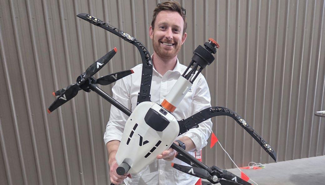
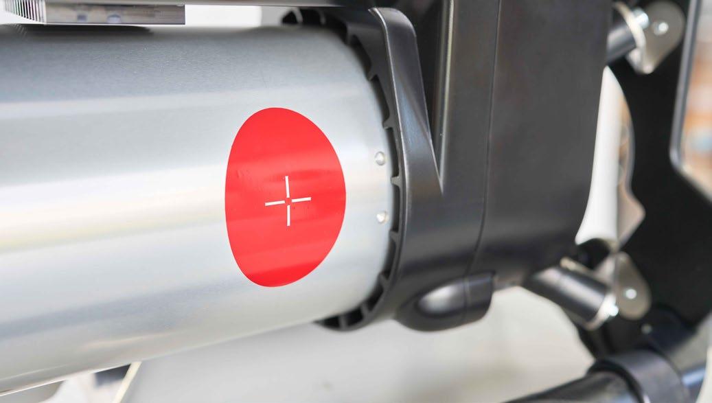
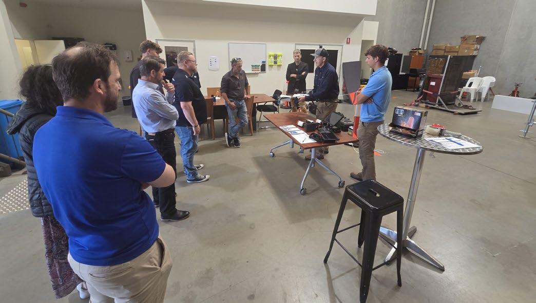
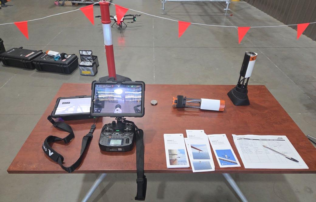
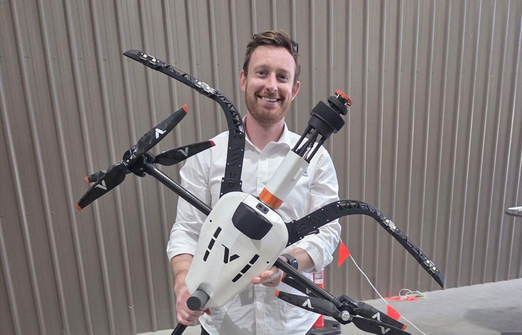
On 26 November, members and guests gathered at NDE Solutions in Hindmarsh for a technical night supported by Voliro. The evening centred on a live demonstration of the Voliro Aerial NDT/LPS Robot, presented by Voliro experts Ferran Torrents and Markus Indermaur, who travelled to Adelaide to showcase how aerial robotics is reshaping the industrial inspection landscape.
Attendees witnessed the robot’s hovering stability, wallcontact capability and sensor integration firsthand— an impressive display of precision and agility that highlighted the potential of aerial platforms for hard-toreach or hazardous inspection environments.
Voliro’s team provided detailed insight into applications across petrochemical plants, power generation facilities, mining, and infrastructure, generating lively discussion among local NDT practitioners about future industry adoption here in South Australia.
The SA Branch extends its thanks to Voliro and to NDE Solutions for hosting what many have described as one of the most exciting technical demonstrations we’ve held to date. Events like this are invaluable for keeping our members connected to the frontier of technological advancement in NDT.
We are pleased to announce plans for the 2026 SA Members Golf Day, returning once again as one of our most popular networking events. While the date is being finalised, members can expect a relaxed, enjoyable day combining friendly competition, industry conversation and plenty of laughs. This event is always a highlight on the branch calendar, and we look forward to revealing full details in the new year.
In early 2026, the SA Branch will host a Guide to Certification (2021) Technical Night, designed to help members navigate the current certification requirements, provide clarity on common questions, and offer guidance on upcoming changes. This will be an ideal session for practitioners seeking certification, renewing their status, or supporting trainees and new technicians. Further details, including date and venue, will be released shortly.
As we look toward a new year, the SA Branch wishes all members, colleagues and industry partners a safe and enjoyable festive season. Your continued engagement and support strengthen our community and help drive excellence in non-destructive testing across South Australia.
We enter 2026 with optimism and enthusiasm, with a calendar already filling with technical events, professional development opportunities and member activities. The Branch Committee looks forward to connecting with you throughout the year and continuing to build a vibrant and forward-looking NDT community.
As 2025 draws to a close, I would like to extend my thanks to all AINDT Victorian members, volunteers, supporters, and industry partners for another productive year. While our calendar included fewer events in the latter half of the year, the work carried out behind the scenes—by councillors and members alike—has helped strengthen our branch, modernise our direction, and build momentum for 2026.
This year we continued delivering meaningful technical engagement through several successful events, including our Guided Wave Ultrasonics night in Williamstown, AI-assisted Radiography Interpretation seminar, and the Laser Welding and Advanced Ultrasonics session held in Ringwood. Each of these provided valuable interaction, knowledge exchange, and the opportunity for practitioners to stay aligned with emerging technologies.
Much of our focus in 2025 centred on improving member value. We developed a comprehensive membership incentive proposal, progressed initiatives around Women in NDT and Young Professionals, and opened conversations about clearer CPD pathways. Work also continued on strengthening career-entry opportunities and formalising support channels for students, early-career inspectors, and those returning to industry.
The council has also been actively reviewing and refining processes such as event certification, membership tracking, award nominations, and recognition for volunteer contributions. While these operational items are often unseen, they are vital to ensuring a well-run, supportive, and progressive branch.
Our AGM this year again brought strong attendance and provided a welcome opportunity for members and partners to connect socially. As always, I extend my sincere thanks to all councillors who contributed throughout the year through meetings, events, and ongoing committee work.
Looking ahead, I am pleased to invite all members and their families to join us for our Victorian Branch Christmas Party at Chesterfield Farm. This will be a relaxed and family-friendly way to close the year and celebrate the contributions of our community.
Thank you again for your commitment to the NDT profession and to the AINDT Victorian Branch. I look forward to working alongside you in 2026 and continuing to strengthen the technical capability, community spirit, and industry leadership of our branch.
Warm regards,
Miro Katouzi President – AINDT Victorian Branch
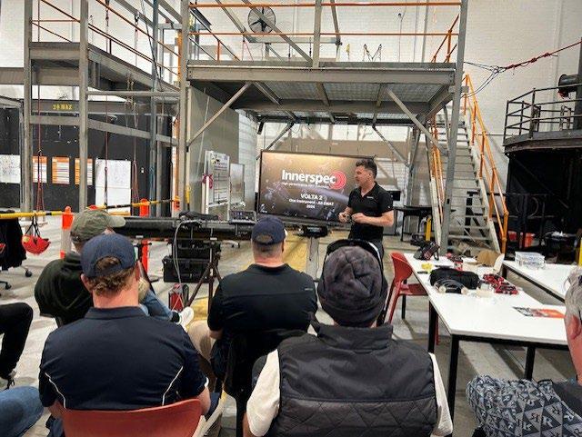
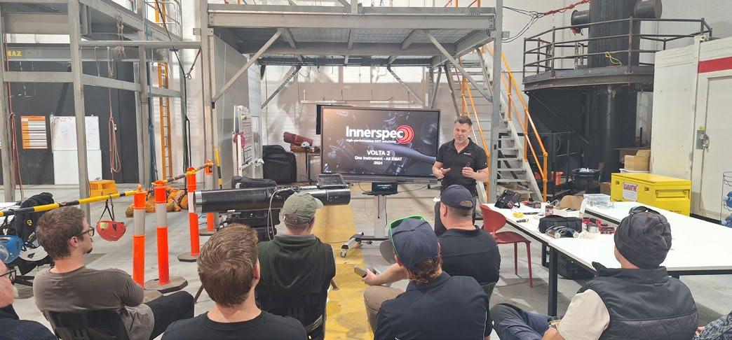
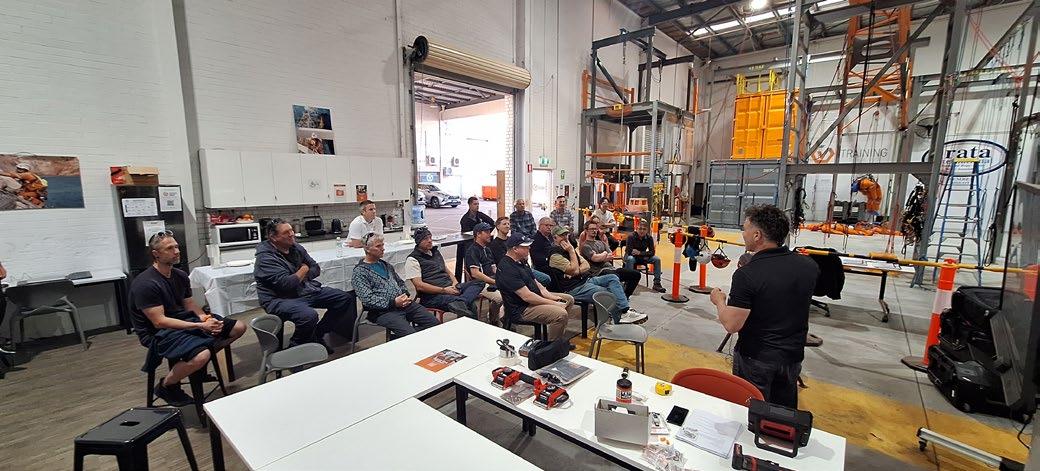
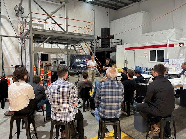
Technical Night: Innerspec VOLTA 2 Guided Wave Technology
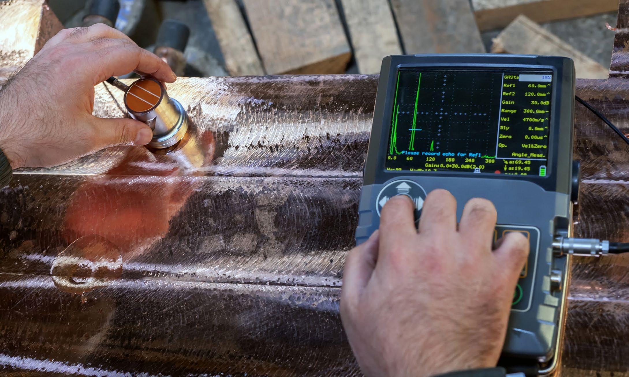
The recent AINDT WA Technical Night, held at Sonomatic’s head office in Perth, featured an engaging presentation by Simplifi NII and Innerspec Technologies on the VOLTA 2 Guided Wave inspection platform.
The session showcased how Electro-Magnetic Acoustic Transducer (EMAT) technology is redefining the way industry approaches pipeline and tank integrity inspections. Attendees explored the advantages of both medium- and long-range guided wave techniques, specifically:
• Axial Lamb-wave scanning for walking-speed inspections of exposed pipework
• Shear-Horizontal screening for corrosion under insulation (CUI), corrosion under pipe supports (CUPS) and buried sections
• Long-Range Ultrasonic Testing (LRUT) for long distance corrosion screening.
The evening concluded with a demonstration of Innerspec’s Patented Defect-Sizing tool, which employs a combined amplitude and frequency cut-off method to quantify defect dimensions with remarkable precision in inaccessible areas.
The event drew strong interest from local NDT professionals keen to see how guided-wave EMATs are expanding the reach of remote inspection capability in Australia’s asset integrity landscape.
In this Standard Update, we have provided the report presented to the CB and FC is a condensed format for the Journal. This year allowed the MT007 committee to further cement itself within the ISO Committees with attendance to all Sector Meetings where membership is held.
AS3978 Visual Inspection was proposed for revision by both the MT007 and WD003 committees and the proposal accepted by Standards Australia. MT007, Paul Grosser chaired the sector meetings with a number of other MT007 members also on the working group, WD003 also contributed with one member. The Standard was presented for public comment which closed on the 13th of November 2025 with no results yet available.
AS1665 was also being revised by the WD003 Welding Committee where they reached out to MT007 for details on certification and how it should be included in the revised Standard. A new clause was proposed by MT007 which was checked for legitimacy by Standards Australia and accepted with one addition point. The new clause details functions for Level 1s, 2s and 3s and may become the norm in all Australian Manufacturing Standards. We would recommend that when this Standard is published for review the Standards chair will notify the AINDT and if possible also put out a notification in the journal.
A number of MT007 Committee Members participated in online ISO Committee (hybrid) meetings that were held in Toronto Canada during June 2025 directly following the PANNDT Conference. MT007 participated at the meetings for sectors where membership is held and the MT007 committee members who attended were as follows:
• ISO/TC 135 (NDT Main Committee) – observing member
• ISO TC 135/SC 3 (Ultrasonic Testing - observing member
• ISO TC 135/SC 4 (Eddy Current) - observing member
• ISO TC 135/SC 7 (Personal Qualification) - participating member
• ISO TC 135/SC 8 (Thermographic Testing) - participating member
• ISO/TC 135/SC 9 (Acoustic Emission) - participating member
During the ISO Committee where it was found that participating country members had not attended two consecutive meetings their membership were downgraded to observing members. Next year MT007 is looking to upgrade their membership status to
participating member on all current sectors where observing membership is held, in addition to becoming observer members on the other sectors where membership is not held.
The TC135 ISO Committee are working on an extensive amount of Standards both new and continually revising older standards. One Standard of interest is the ISO/TC 135/SC 8/WG 4 "NDT-IR-Guidelines for examination of electrical installations" which appears to be also similar to current ISO IR Standards proposed for Condition Monitoring.
ISO TC135 Main Committee also discussed the possibility of another Sector for Magnetic Flux Leakage with a combination of Eddy Current and Magnetic Particle committee members and also allowing new committee members as well.
2025 also had some difficult periods due to the changes in Standards Australia Project Manager. It is expected that a number of meetings will occur early in 2026 where MT007 will be looking at the following
• What ISO Standards can be adopted due to no Australian Standard or replace current Australian Standards with the first to be considered being Acoustic Emission, then working through other NDT methods in particular advanced methods, however traditional UT of welds is not being considered at present due to the differences and Australian manufacturing standards.
• The nominating of other MT007 members who have expertise in their areas to be on ISO Committees so that the ISO Sectors can be spread out amongst the full MT007 committee.
• Applying for observer status on ISO TC 135/SC2 Surface Methods, TC 135/5 Radiography, TC 135/6 Leak Testing.
• Upgrading observer member status to participating member on ISO TC 135 Main Committee, TC 135/SC3 Ultrasonic Testing and TC 135/SC4 Eddy Current.
Angelo Zaccari MT007 Standards Chairperson. angelo.zaccari@outlook.com
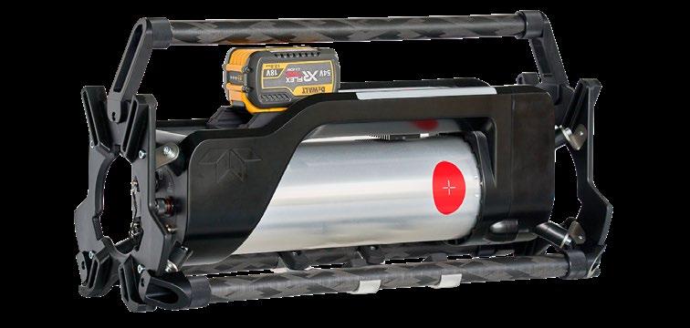
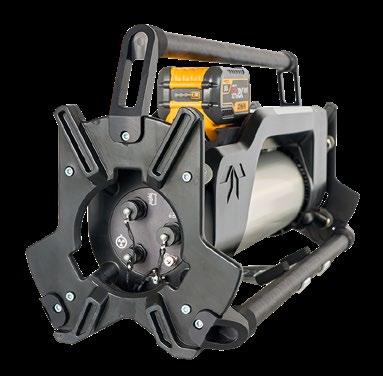
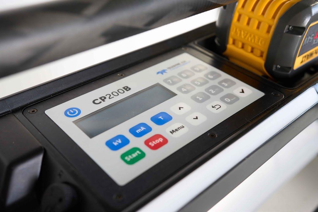
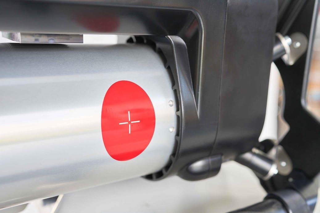
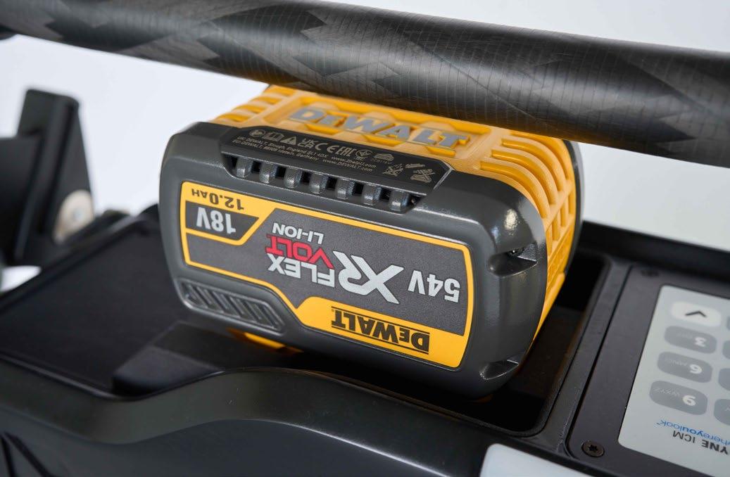
The CP BATTERY CP200B is a groundbreaking battery-operated portable X-ray generator designed to deliver unmatched performance, mobility, and versatility for NDT applications.
True Portability and Autonomy: Powered by a DeWalt® 54V battery system, the CP200B eliminates power cord constraints, enabling inspections in the most remote or challenging environments.
High Performance in a Compact Form: Despite its lightweight design (15 Kg ~ 33 lbs), the CP200B delivers an impressive 40 to 200 kV output voltage and 0.1 to 1.5 mA tube current, ensuring adaptability for a wide range of inspection needs.
100% Duty Cycle: Thanks to its advanced air-cooling system, the CP200B operates continuously even in demanding conditions, maximising productivity.
Precision Imaging with Small Focal Spot: Featuring a 0.8 mm focal spot (EN 12543), the CP200B ensures high-resolution images, making it the ideal partner for digital radiography and (CUI) Corrosion under Insulation critical inspections.
Next-Level Connectivity: Beyond its wired and wireless control options, the CP200B introduces a dedicated web interface, allowing inspectors to control the unit remotely from any device with a browser, no additional software required. It also integrates seamlessly with Sherlock NDT software and Go-Scan digital detectors, enabling real-time image acquisition and analysis.
Rugged and Reliable: Built for harsh environments, the CP200B is IP65-rated (battery excluded).
ASG NDT SUPPLIES are the Australian / New Zealand Agent for Teledyne ICM.
For further information, please contact: chris@asgndtsupplies.com
+61 (0) 455 552 895 (AUS)
+64 (0) 273 219 901 (NZ)
Thermography is rapidly becoming a standard tool across many industries in Australia, but nowhere is it more critical than in the electrical sector.
Used for both project handover verification and ongoing maintenance, thermography enables inspectors to detect faults invisible to the naked eye—long before failure or power loss occurs.
Yet, what is often overlooked is the depth of technical knowledge and experience required to conduct highquality inspections. Understanding not just the thermal image but also the electrical science behind it is essential. This is particularly true when dealing with Surge Protection Devices (SPDs).
Surge Protection Devices: A Quick Overview
SPDs are designed to divert dangerous high-voltage surges (commonly caused by lightning) away from sensitive equipment. They are considered consumable items because their internal components degrade over time.
Most SPDs rely on Metal Oxide Varistors (MOVs), which connect active phases to earth once voltage rises above a set threshold. Over repeated surges or high-energy events, MOVs can break down, sometimes resulting in a dangerous short circuit at normal operating voltages.
Manufacturers include indicator flags or status lights to warn of failure. More advanced SPDs can even send signals to control systems. But, as with many safety devices, these indicators are not foolproof.
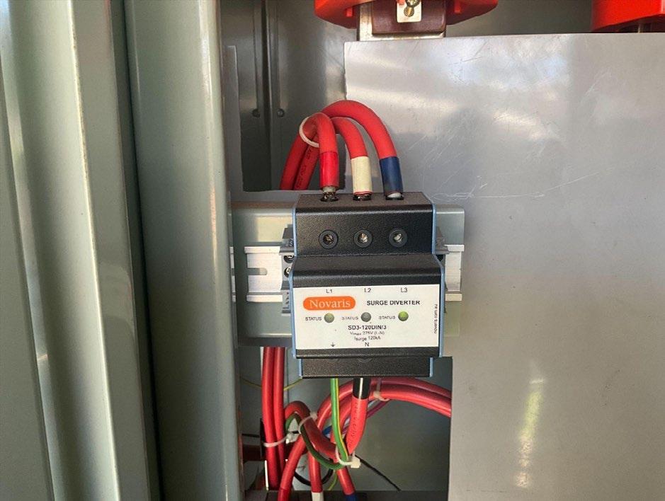

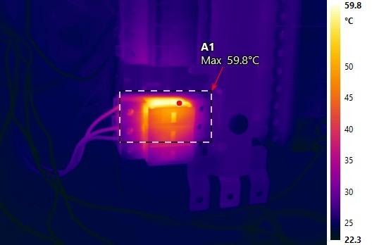
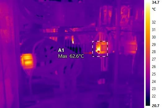
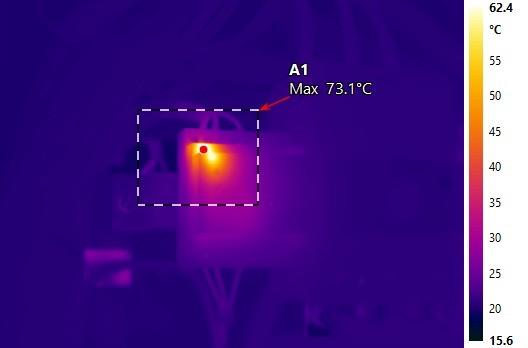
During a recent site inspection, Thermal Scanners identified an SPD running at over 60 °C on its side face (Figure 2). Surprisingly, the indicator flag showed no fault. A later continuity test completed during site shutdowns confirmed a short circuit between active and earth.
This case highlights why thermography is invaluable: even when the indicator fails, a trained thermographer can spot the warning signs early enabling planning and replacement before failure.
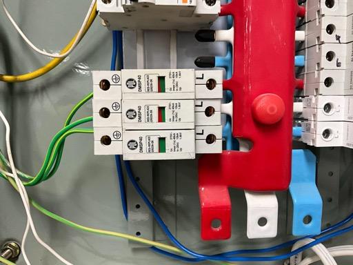
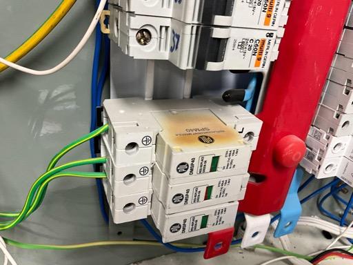
SPDs should always be installed in series with fuse current limiters or suitably sized MCBs, as specified by manufacturers. This ensures over-current and shortcircuit protection if MOVs fail.
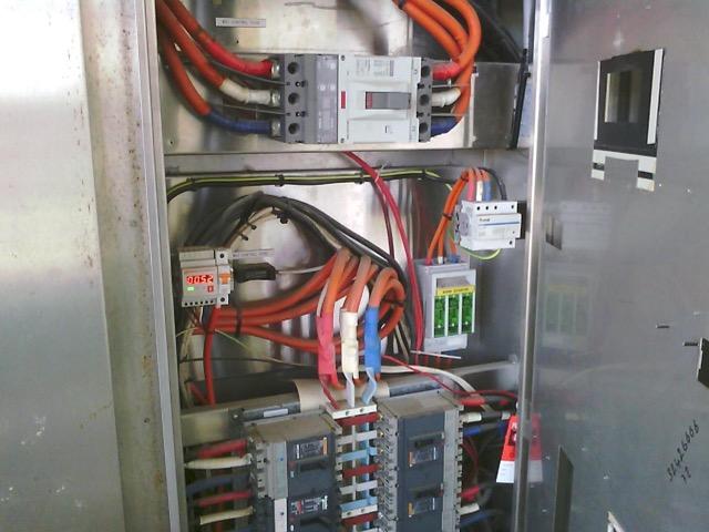
However, not all installations follow this rule. In one inspection, Thermal Scanners found SPDs wired directly to a distribution chassis with non-functioning flags (Figure 3).
Thermal images revealed active leakage and burn marks (Figure 4). Interestingly, the red phase registered the highest temperature, even though the indication flag was only showing failure on the white phase.
Study 3: When Heat doesn’t indicate a failed MOV
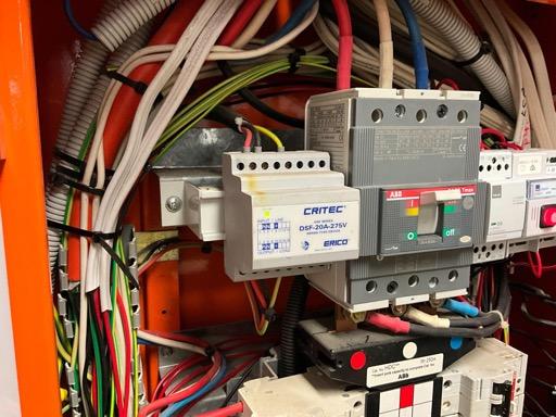
It’s important to note that not all hot spots mean a failed SPD. For example, Type 2 series SPDs with filters (such as the Critec Surge Filter) often show elevated temperatures on the upper casing due to their internal LED driver, not increased heat due to MOV breakdown (Figure 5).
Without proper knowledge of both thermography and the equipment, inspectors could easily misinterpret this as a fault. In this case, collaboration with the manufacturer confirmed the readings were not due to issues relating to surge diversion.
These examples demonstrate several key lessons for electrical professionals:
• Indicators can fail: Thermography adds a critical safety layer.
• Correct installation matters: SPDs must be paired with fuses or MCBs to prevent catastrophic short circuits.
• Not all heat is dangerous: Distinguishing between harmless thermal effects and genuine risks requires training and manufacturer knowledge.
Thermography is not just about pointing a camera at a switchboard. It’s about interpreting the results in the context of electrical engineering. As surge diverters and protection devices become more vital to modern networks, the role of qualified, experienced thermographers is critical.
By combining infrared imaging with a deep understanding of SPDs, technicians can spot hidden risks before they escalate into failures. In today’s electrical environment, that difference can mean the safety—or the shutdown—of an entire installation.

With a career spanning hands-on technical work and leadership in operations, Nathan Thompson embodies the curiosity and commitment that define the nondestructive testing (NDT) profession.
Currently serving as an NDT technician, operations manager, and welding inspector and supervisor at Independent Testing and Inspection Services, Nathan’s journey began on the tools as a boilermaker and evolved into a multifaceted role balancing precision, people, and process.
Driven by a passion for problem-solving and continuous learning, Nathan has built his career on a foundation of quality and safety; values reinforced through the mentors who guided his progression from welder to NDT professional. From largescale infrastructure projects to mining equipment builds in China, he has seen first-hand how non-destructive testing underpins the reliability of complex assets.
In this member profile, Nathan shares insights from his professional journey, lessons learned from industry mentors, and advice for those starting out in NDT.
Where do you work? Describe your job.
I currently work at Independent Testing and Inspection Services as an NDT technician, operations manager, and welding inspector and supervisor.
My role spans both technical and managerial responsibilities. On the technical side, I’m involved in ultrasonic testing, radiography, visual, magnetic particle and liquid penetrant inspections, as well as welder and procedure qualification.
As an operations manager, I oversee scheduling, team coordination, safety compliance, client communication, and report review and issue. In my NDT and welding inspector and supervisor role, I ensure quality standards are met on critical projects, balancing efficiency with safety and compliance.
Can you share your journey into the NDT industry? What motivated you?
My path into NDT wasn’t a straight line. I began as a boilermaker and welder, where I first encountered NDT by seeing my welds tested, and even testing my own welds before inspections.
That experience sparked my curiosity. What drew me in was the combination of science, problem-solving, and the real-world impact of ensuring safety and reliability in industries such as plant maintenance of pressure vessels, piping, and construction.
Over time, I realised NDT was more than just a job. It was a career where I could keep learning and contribute to projects that matter.
Who or what has influenced you most professionally?
I’ve been fortunate to work with mentors who shaped my approach to both technical excellence and leadership. Kevin Wooden encouraged me to pursue this path after welding. James Johnson influenced me in both NDT and welding supervision.
Adam Lees taught me the finer details, while Vick Mierzwa gave me a whole new perspective on technical and quality management. Their guidance instilled in me the importance of precision, accountability, and continuous improvement.
What has been the most interesting project you’ve worked on and why?
Some of the most memorable projects I’ve worked on include building mining equipment in China, large-scale infrastructure builds, and shutdowns.
Each stood out because of their scale, complexity, teamwork, and the stakes involved. These projects reinforced the importance of collaboration and highlighted how NDT plays a critical role in keeping people safe and assets reliable.
What advice would you give to someone just starting their career in the NDT industry?
Be curious and never stop learning. Be prepared to work hard. The industry is constantly evolving with new technologies and standards, so adaptability is key.
I’d also say: don’t underestimate the value of communication and teamwork. Technical skills are essential, but the ability to work well with others and explain your findings clearly is what makes you stand out.
What has been your greatest professional achievement?
Earning all of my certifications has been a highlight of my career. It was rewarding because it reflected not only applied knowledge and technical skills but also the dedication and discipline required for study and professional growth.
How has being a member of AINDT benefited you?
Being part of AINDT has connected me with a network of professionals who share the same passion for NDT. It has given me access to training, resources, and industry updates that keep me sharp and informed. On a personal level, it’s motivating to feel part of a community that values excellence and innovation.
What are the top three things on your bucket list?
1. Witness the Northern Lights
2. Earn my pilot’s licence
3. See the Milky Way from the Atacama Desert
Rapid Fire
• Favourite food
Vietnamese
• Favourite song
Fade to Black (Metallica), The Pot (Tool)
• Favourite sport
Just about all sports
• If you could be famous, what would it be for?
Being anonymous
• If you could meet anyone (alive or dead), who would it be?
Archimedes or Leonardo da Vinci
• Pet peeve
People driving slowly in the right-hand lane
• Top tip for NDT excellence
Attention to detail is everything
In an industry where accuracy, traceability, and turnaround times directly influence operational safety, Nuclear Australia is emerging as a leader in radiation measurement services.
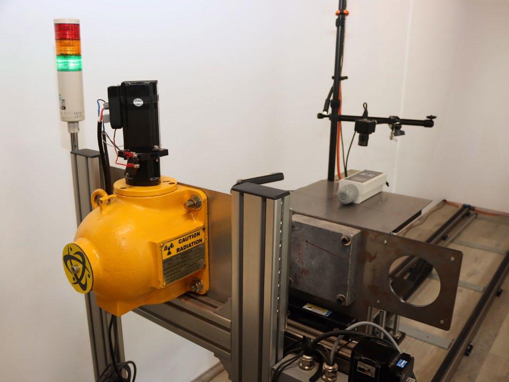
From its dedicated facility in Carrum Downs, the company delivers rapid, technically rigorous gamma survey meter and dosimeter calibrations with a guaranteed 48-hour turnaround. Central to this capability is the company’s in-house designed Gamma Calibration System (GCS), a sophisticated, purposebuilt platform engineered to provide repeatable, high-confidence calibration results across a broad measurement range.
At the core of the GCS is a 3-metre computer-controlled track system that positions instruments with millimetrelevel precision along a graded radiation field produced by a 10 GBq Cs-137 source. The track supports a high-precision table on which instruments are mounted before being translated through the beam. This geometry provides a highly stable and predictable dose distribution, enabling calibrations from 2,500 µSv/h down to 5 µSv/h, with most instruments tested at eight discrete set points to verify linearity, response stability, and range-specific performance.
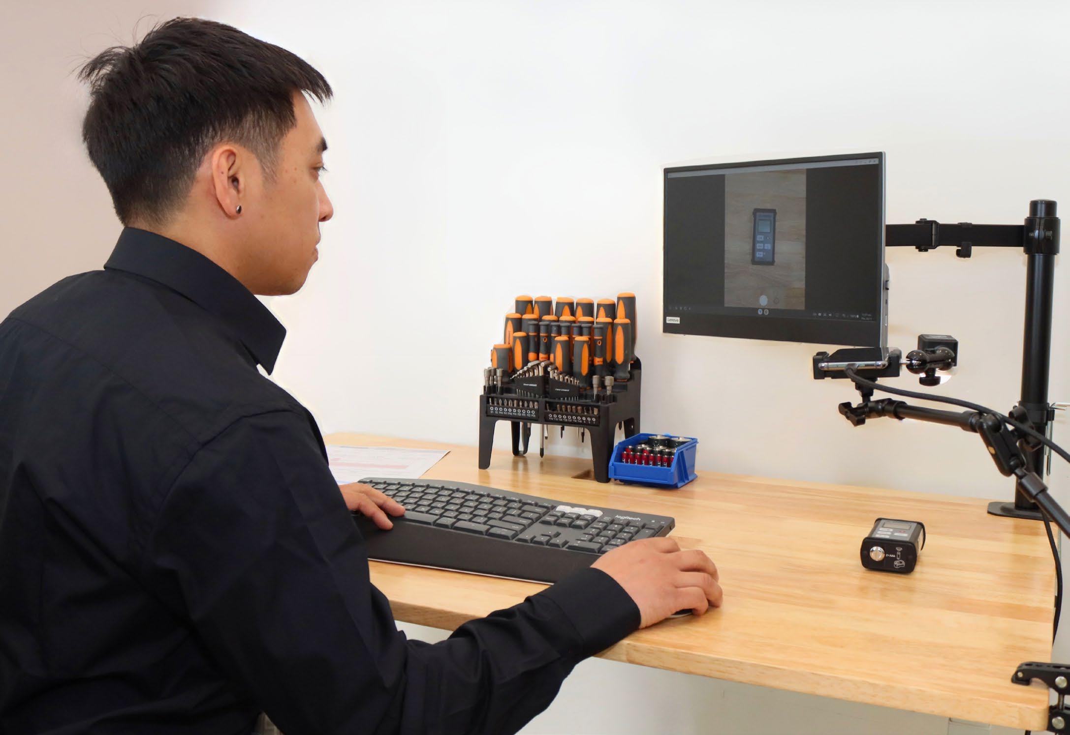
What distinguishes the GCS from more conventional fixed-distance or enclosure-based calibration rigs is its integration of automation, imaging and analytics. During testing, the system captures live digital images of the instrument at each calibration point, documenting orientation and setup.
These images are embedded directly into the instruments calibration certificate, giving unprecedented visibility into the exact conditions under which their instruments were calibrated. For each range, the GCS records three independent measurements and automatically calculates a calibration factor, which is later plotted onto the certificate to provide a clear graphical representation of the instrument’s performance over the entire field.
The system is, in essence, a practical, carefully engineered demonstration of the inverse square law—a fundamental principle governing photon fluence and dose rate. All dose rates produced by the GCS are fully traceable to the National Standard for Air Kerma, ensuring alignment with national and international metrological expectations.
Nuclear Australia is currently progressing through ISO 9001 certification, with NATA accreditation targeted for 2027, reinforcing the company’s commitment to robust quality systems and continuous improvement.
However, the technological sophistication of the GCS is only part of what defines the Nuclear Australia calibration experience. Every instrument that enters the facility is processed through a structured, transparent, and highly traceable intake workflow.
Upon arrival, devices are logged into the company’s laboratory management system—Wilhelm, named in honour of Wilhelm Röntgen, the discoverer of X-rays. Wilhelm acts as the backbone for data integrity, recording the instrument’s make, model, serial number, and operational notes, alongside high-resolution photographs documenting the condition of the device as received from the customer. These intake images can be provided to customers on request, supporting a fully auditable calibration history.
Once entered into Wilhelm, instruments undergo a comprehensive pre-calibration assessment. The technical team inspects each device for defects, mechanical issues, or anomalies that may affect performance. Replaceable batteries are exchanged for professional-grade cells to eliminate power-related variability during testing. Instruments with rechargeable battery packs undergo a short test-charge cycle to confirm stable performance.
All preliminary checks are recorded and ultimately included on the calibration certificate, ensuring customers receive a complete record of the instrument’s condition and any actions taken prior to calibration.
Following this assessment, instruments are transferred to the GCS for calibration. Once completed, the system generates a detailed calibration report, including calibration factors, plotted performance data, and the captured image set. The report is archived within Wilhelm and used to produce a durable, high-wear calibration sticker affixed to the device. These labels display key dates, instrument identifiers, and calibration factors.
A particularly valued feature is the QR code, which provides instant digital access to the full calibration certificate—an essential convenience for field technicians who need real-time verification documentation.
Before dispatch, each certificate undergoes a formal review by a senior manager to ensure compliance
with internal quality procedures. Instruments are then securely packaged in new cartons and dispatched, ensuring customers across Australia receive their equipment promptly and ready for operational use.
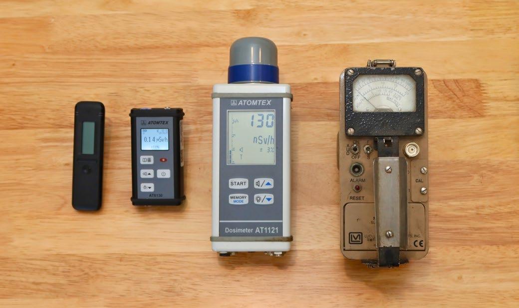
Beyond calibration, Nuclear Australia’s facility also houses a radiation services division offering sealed source storage and disposal, wipe-testing facilities, and a curated selection of radiation detection instruments from industry-leading manufacturers such as Berthold, Bertin, Atomtex, and Polimaster. These services are supported by a dedicated electronics R&D and repair laboratory, enabling rapid fault diagnosis and repair of instruments from major brands including Thermo Fisher Scientific, Atomtex, and Berthold. This integrated capability means customers can rely on Nuclear Australia not only for calibration, but for ongoing maintenance, technical troubleshooting, and long-term fleet support.
Through its blend of advanced engineering, meticulous workflow management, and expanding quality accreditation, Nuclear Australia is strengthening Australia’s domestic capability in radiation measurement and calibration. As regulatory expectations evolve and industries demand ever higher levels of accuracy and traceability, the company stands well positioned to support the nation’s scientific, industrial, and emergency-response sectors with fast, reliable, and technically robust calibration services.
For more information, visit: nuclearaustralia.com.au
As battery technology advances, the need for reliable and efficient energy storage solutions becomes increasingly important.
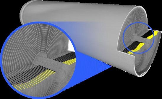
One critical aspect of battery performance and safety is the interaction between the anode and cathode materials and their relationship to the overall battery architecture. Battery electrode assemblies, also known as stacks or jelly rolls, form the core of modern energy storage systems. These assemblies consist of anode and cathode sheets, where anode sheets are typically larger than cathode electrodes. The spatial gap between the larger anodes and the smaller cathodes is termed as the anode overhang (AO). This overhang has a significant impact on battery performance, necessitating precise alignment to optimize cell efficiency.
Anode overhang, where active materials extend beyond their respective current collectors, can significantly impact battery efficiency and cycle life.
Attaining impeccably aligned electrode assemblies with consistent AO is pivotal for upholding efficient charge and discharge cycles. If certain tolerances are exceeded, the cells can potentially become a safety hazard. Due to the oftenflammable electrolyte, a sudden discharge can lead to a thermal runaway.
X-ray micro-CT is a powerful non-destructive imaging technique that provides 3D insights into the internal structure of materials with micron-scale resolution. This technique involves the use of X-rays to generate virtual cross-sectional images of a sample, which can
then be reconstructed to visualize the internal features in three dimensions. By using advanced image analysis techniques, researchers can quantify the extent of anode overhang, enabling a deeper understanding of the impact on battery performance:
Visualize and quantify Overhang: Obtain 3D representations of electrode overhang, aiding in identifying its extent and location.
Optimize Electrode Designs: Design electrodes with reduced overhang to enhance battery performance and lifespan.
Validate Simulation Models: Compare experimental findings with simulation results to validate and improve predictive models of electrode behavior.
Advance Battery Technology: Improve overall battery design and operation by addressing issues related to anode overhang.
To illustrate the practical application of TESCAN micro-CT, one can look at the investigation on AnodeCathode Overhang (ACO) in Figure 1. The dataset, sourced from a CT scan of an 18650 Li-ion battery at a spatial resolution of 15 µm, was acquired using the TESCAN UniTOM XL. Leveraging dedicated 3D analysis software like VG Studio Max by Volume Graphics, we can effortlessly segment the anode’s current collectors.
Figure 1. Shows a visualization of the anode overhang, highlighted in yellow, within the whole cylindrical 18650 cell. This representation brings solid ground for the initial evaluation of variations in overhang lengths within the cell.
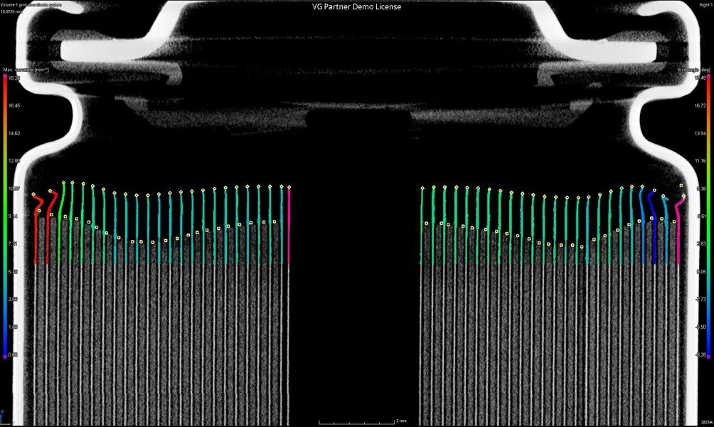
One of the standout benefits of micro-CT data is its inherent volumetric nature. This allows for analysis on any virtual cross-section, irrespective of its orientation. But the capabilities of image analysis software extend beyond just visualizing overhang lengths. They provide a comprehensive view of other structural parameters, such as curvature and exit angle. Image analysis tools enable data visualization in innovative ways, such as color-coding overhangs based on their exit angle from the cathode, as seen in Figure 2.
In summary, X-ray micro-CT is an indispensable tool for investigating battery anode overhang. Its nondestructive nature, high-resolution imaging capabilities, and quantitative analysis potential make it an essential technique for understanding the impact of overhang on battery performance. Incorporating micro-CT into battery research efforts will facilitate the development of more efficient and reliable energy storage solutions for various applications, ultimately driving advancements in battery technology.
Rotor rub is one of the most common, and potentially damaging, faults encountered in rotating machinery. It occurs when a rotating component comes into contact with a stationary part that was never designed for contact.
BY SALAH ATTIA
While bearings and certain seal types are engineered to operate with controlled contact or a film of lubrication, any unplanned rubbing elsewhere in the system can quickly escalate into a serious mechanical and operational issue.
In machinery such as turbines, compressors, and pumps, rubs often develop as a secondary fault; the symptom of an underlying condition rather than the primary cause. These underlying conditions might include shaft bow, rotor unbalance, fluid-induced instability, misalignment, preloads, insufficient clearances, or casing distortion due to uneven thermal growth.
Regardless of the source, the effect is the same: direct contact between rotating and stationary parts that leads to wear, heat generation, vibration, and ultimately, potential failure.
Types of Rub
Rotor rubs can generally be classified into three types: axial, radial, and conical.
• Axial rubs occur along the shaft’s lengthwise direction and often result from axial movement or thrust issues.
• Radial rubs happen perpendicular to the shaft’s axis, typically due to imbalance, misalignment, or clearance problems.
• Conical rubs are a combination of the two, creating a spiral-like contact pattern that can be especially destructive because it affects both axial and radial planes.
Identifying which type of rub has occurred is crucial to diagnosing the underlying mechanical fault and determining corrective action.
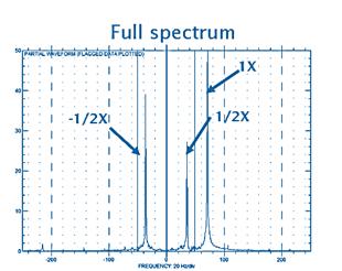
The most effective way to detect and analyse rotor rubs is through vibration monitoring and spectrum analysis. A rub commonly appears as a running-speed (1X) vibration component accompanied by harmonics on the reverse side of the full spectrum, often with an additional subharmonic component.
The relationship between running speed and the system’s natural frequency also provides clues:
• When the running speed is less than twice the natural frequency, the rub tends to appear as 1X with harmonics.
• When the running speed exceeds twice the natural frequency, both 1X and ½X components are likely to be visible.
This frequency pattern is a key diagnostic indicator, helping engineers confirm the presence of a rub and assess its severity.
Preventing and Managing Rotor Rub
Prevention begins with good design, maintenance, and operating discipline. Adequate clearances, balanced rotors, and well-aligned shafts reduce the likelihood of mechanical contact. Monitoring systems that track vibration trends and temperature fluctuations can detect early signs of rub-related instability before damage occurs.
When a rub is identified, it is important to treat it as a symptom, not just a fault. Correcting the underlying cause (whether it’s a thermal growth issue, a lubrication problem, or an imbalance) is essential to preventing recurrence.
The Bigger Picture
Rotor rubs may start small, but left unchecked, they can lead to severe degradation of bearings, seals, and other critical components. Understanding how and why they occur allows maintenance teams to move from reactive fixes to predictive and preventive strategies.
In essence, rotor rubs tell a story, one of imbalance, distortion, or design compromise. Reading that story correctly through vibration analysis and engineering insight is what keeps rotating machinery running smoothly, efficiently, and safely.
Salah Attia

Technical Director at MCS, introducing a range of services to our customers, including vibration and oil analysis, thermal imaging, alignment, balancing and training (VCAT4, TCAT3, MLA2, CMRP, NER, RPEQ, MIEAust)
Email: salah attia@mcsturbo com
Phone: 0499881294
www mcsturbo com
www mdiaustralia com
Rub occurs when a rotating part is in contact with a stationary part that is not designed for such contact. The only parts designed for contact are bearings and some seals. In the fluid bearing, the contact should be maintained through a film of oil In the types of seals that allow some contact by design – either constantly during operation (oil seals) or occasionally (carbon seals, brush seals, and honeycomb seals), A rub is usually is a secondary fault which happen due to initial cause such as:
Unbalance
Shaft bow
Fluid induced instability
Misalignment and preloads
Insufficient clearance (problem with design or maintenance).
Casing distortion and uneven thermal growth
Rubs Types:
Axial rub
Radial rub
Conical rub
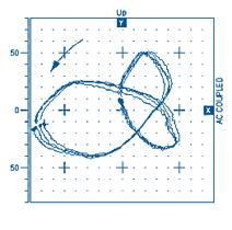
Analysis:

The rub appears on the vibration spectrum as running speed 1X with harmonics mostly on the reverse side of the full spectrum in addition to the subharmonic component too.
Rubs could appear as 1X with harmonics when the running speed < 2 times the natural frequency. Rubs could appear as 1X and 1/2X when the running speed > 2 times the natural frequency
Acoustic Emission Testing (AET) is a Non Destructive Testing (NDT) technique used to confirm structural integrity through the identification of active corrosion, cracking and plastic deformation of materials in structures and members, including pressure vessels, tanks, ship hulls and other supporting structures. Aside from fundamental structural integrity confirmation AET has a wide application base and can determine whether a storage tank is leaking, a valve is passing, or a bearing has spalled, as well as having many other functions.
BY DAVID LAKE AND GARY MARTIN, ADVANCED TECHNOLOGY TESTING AND RESEARCH (ATTAR)
Introduction
With AET, in-service damage is recorded with sensors as it is occurring through the detection of the transient stress waves released into the material. Distinguishing itself from many other NDT techniques, AE has the ability to monitor components during operation, allowing the synchronisation between defect growth and operational characteristics.
Unlike many other NDT methods, the sensors typically are not placed directly over a defect to record growth. In fact, a relatively small array of sensors can monitor a whole structure or area, providing a global inspection tool which can observe deterioration in otherwise inaccessible locations.
Monitoring of defects can either be done through the installation of semi-permanent AET sensors, which detect growth when in-service conditions are present, or through the use of controlled stimulation to determine whether defects present are actually active when standard operating conditions are marginally exceeded.
Acoustic emission may also be used for localised monitoring of existing flaws, monitoring their growth and serving as the basis for scheduling follow-up examinations in lieu of periodic, regularly scheduled examinations. Acoustic emission monitoring may be especially desirable for locations on a naval vessel that are difficult or impossible to access by other methods. AET is conducted with the guidance of a suite of AET Standards including Australian (AS), American Society for Testing and Materials (ASTM), The American Society of Mechanical Engineers (ASME) and The International Organization for Standardization (ISO) Standards.
• 1950 – Josef Kaiser (Germany) used tensile tests to determine the characteristics of Acoustic Emission in
engineering materials.
• 1960s – “Dunegan” worked on inspection of high pressure vessels, and Acoustic Emission monitoring was used successfully for detecting the loss of coolant in a nuclear reactor.
• 1970s – Dr Gary Martin (then with DSTO now Chairman and Technical Director of ATTAR) researched Calibration techniques and worked on in flight monitoring of cracks in a Macchi Jet.
• 1980s – In Australia, monitoring of FRP (Fibre Reinforced Plastic [Composite]) booms in Elevated Work Platforms and FRP sewer outfall pipes commenced.
• 1990s – There were approx. 30 programs conducted to validate the use of Acoustic Emission including EPRI’s work on high pressure steam lines.
• 1998 – “Van De Loo” released the outcome of a large survey of results that showed a good correlation when comparing AET for petrochemical tank monitoring and traditional NDT testing of the floors.
Today, AE Non-Destructive Testing is used in many industrial sectors around the world for different types of structures and materials. ATTAR has been offering high quality AET across a range of industries since the late 80s, including testing of Pressure vessels/tanks/ pipelines (steel and composites), composite insulating boom sections of EWPs (including participating in the development of the Australian Standard AS 4748 –2001), structures (e.g. bridges) and the monitoring of creep in high pressure, high temperature steam lines.
Applications
Structure stimulation
The application of a controlled stimulation, either progressively applied or applied in stages, with the presence of AE sensors, allows the structure to be monitored during loading conditions which are similar or greater than their standard operating conditions.
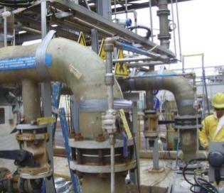
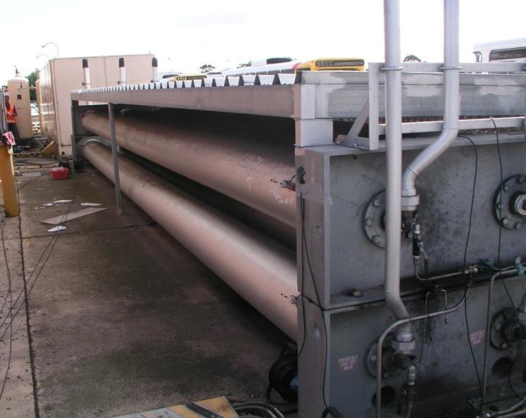
Smaller defects which are active at operating stress levels, which might otherwise be missed by other less sensitive NDT methods, can be detected, located and then marked for inspection using complimentary NDT methods for sizing.
Utilising the existing International Standards and ATTAR’s procedures to tailor specific AET procedures for a variety of applications, provides Engineers with the means of gaining confidence in the testing of an asset. High-risk assets, such as vessels, cylinders, pipelines and more, are safely monitored during a controlled stimulation process.
AET is regularly used to assess tank floors, where access to this region is otherwise impossible without the difficult, lengthy and costly processes for draining, gaining access and cleaning. Where a
regular programme of AET is undertaken and included in the assessment of the Risk Based Inspection (RBI) programme, good judgements on the tank condition can be made and internal inspections deemed not necessary, until the RBI assessment results indicate a deleterious change. Where tanks have been in service for some time without an inspection, AET results tend to be used to prioritise which tank or vessel to inspect and when internal inspections could safely fit with operational schedules and plans. Following this inspection giving a base condition, AET can then be used with greater confidence to monitor the condition of the plant.
Inspection of fuel, ballast, waste-water tanks and pressure vessels could be quickly performed with the installation of permanent sensors or, if access is provided during docking periods, temporary sensors could be placed and testing conducted.
General machinery and plant compartments where access is limited, ventilation is poor, or humidity is high can be inspected with AET.
Land based fuel tanks can remain operationally ready by reducing the need for internal inspections, through the introduction of an RBI programme that incorporates AET.
Examples: Testing for corrosion and leaks in the floor of an above ground storage tank, sensors are evenly spaced around the wall of the tank, at about 1 metre from the floor, to enable the whole floor to be monitored for corrosion (or leak) activity. The attenuation is then measured through the “liquid” in the tank to enable accurate location of the activity. A second set of guard sensors are then attached about 1m above these to enable the operator to remove from the collected data, any extraneous “noise” that is emanating from the upper wall and roof (e.g. dust blown against the tank, birds landing on the roof, etc.)
When testing for structural integrity and corrosion in a spherical pressure vessel both the liquid/gas containment sphere and leg supports can be tested at
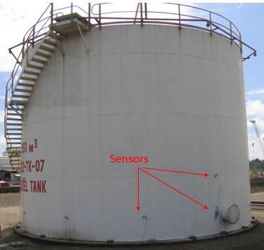

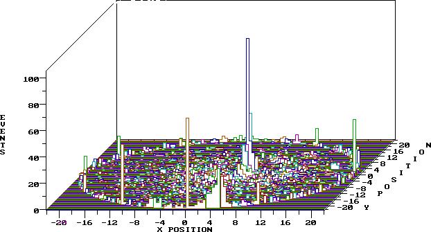
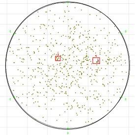
one time. Here “attenuation/signal loss” can be affected by the insulation contact with the surface, which can affect the spacing/number of sensors required to get full coverage with adequate sensitivity.
For high pressure steam lines monitored over a number of weeks looking for cracking/creep, a number of measured parameters can be displayed for an analysis of the activity.
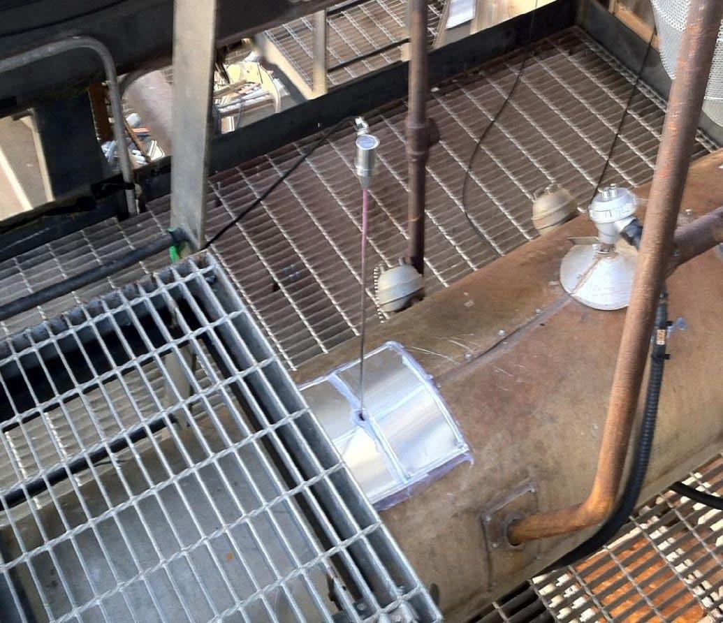
Acoustic Emissions can generally be divided into two categories; material acoustic emissions generated by local dynamic changes in the material structure and mechanical acoustic emissions originating from such things as friction, leaks and impact.
Sensors have been designed to operate in the 30 to 300 KHz range, to enable better resolution of emissions that are being measured. The AE equipment also collects the waveform of the emission, enabling analysis of the mechanism that is giving rise to the emissions.
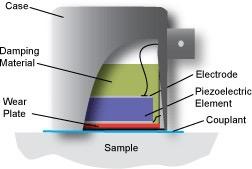
Figure 10 Cross section of an AE Sensor. Typical sensor frequency and applications 30kHz (Tank bottom monitoring), 60kHz (Fibre composites), 150kHz (Metallic structures) and 300kHz (High pressure piping).
The morphology of the detected transient elastic waves varies depending on the type of emission. The characterisation of the waves is made possible using high-speed, high-resolution hardware, capable of modelling both the physical and dimensional waveform properties. Using these characteristics, distinguishing between different noise source types becomes possible.
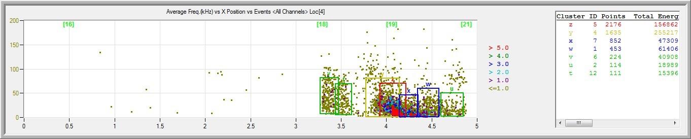
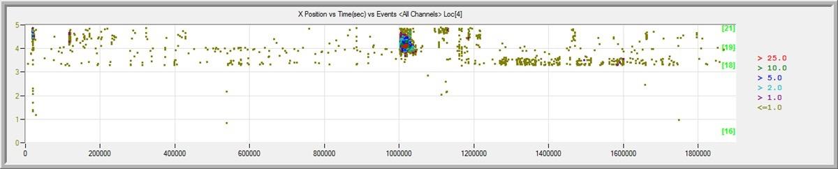
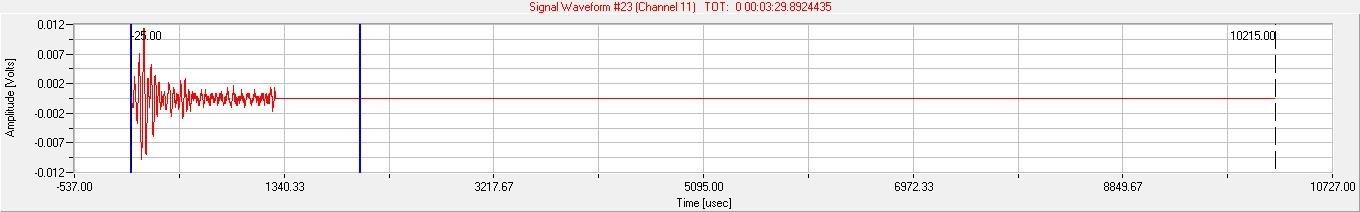
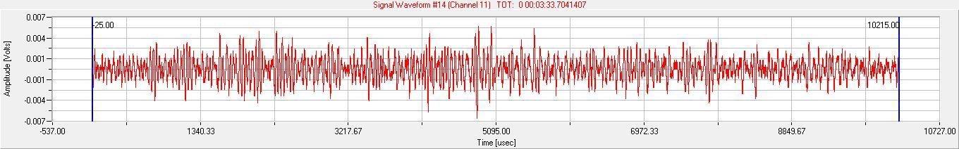
Two waveforms are shown below. Figure 11 is typical of crack-like acoustic emissions, where it presents as a short, sharp signal. Figure 12 is more consistent with mechanical rubbing, where there is a longer duration, and a more even appearance.
AE sensors are typically piezoelectric, made of PZT and most include a preamplifier to reduce electromagnetic interference with signals. The sensors are attached and “coupled” to the material surface, with calibration confirmed with the sensor located on the material of the structure to be tested.
Designing an AET programme usually involves the asset owner, operator, or engineer working with the AE engineer to determine what can realistically be achieved, potentially by answering questions similar to those below.
• What is the objective of the testing/monitoring (what do you want to know)?
• What are the access limitations and surface conditions of the tank, pressure vessel or structure?
• What sensitivity is wanted (bearing in mind that detects plastic deformation prior to crack growth)?
• What is the material of construction (steel, aluminium, composite)? Is it coated? If for example a tank, then what liquid does it contain, how full is it and is there “sludge” present?
• What material failure type is of concern (e.g. corrosion, cracking, leaks)?
• What “background noise” is present? Filtering techniques used to distinguish this, from the AE given off by the failure mechanism, will greatly influence the duration of the testing/monitoring and the location of the sensors.
• Is there a need to assess what is causing the crack to grow or when the corrosion is occurring?
• Can the structure be stressed above those stresses it is subjected to in operation, or can defect growth only be induced during operation?
Once appropriate questions similar to those above have been answered, then the AET programme can be designed.
• Type/Frequency of the sensors to be used
• Location of sensors
• How stress is to be applied to the material
• Duration of test
• Recording of associated parameters e.g. temperature, pressure, load, speed, stress that may be linked to the acoustic emission generation.
An assessment is made as to whether enough information can be obtained in dock, or whether in-service monitoring is required.
The most important factor in ensuring the success of an AET programme is the selection of the AE expert operator’s capabilities, for example:
i. Ensure the AE supplier (company) has experienced AE personnel, e.g. a Level III with greater than 10 years (solid) experience. Level II AE practitioners with greater than 5 years’ experience. The Qualifications are most likely to be ASNT TC 1a.
ii. The AET supplier has credentials showing successful AE field operations over a number of years.
iii. The supplier has ISO 17025 accreditation for AE testing (NATA in Australia). This shows that they have testing procedures and protocols, and they are accredited for the type of work to be undertaken.
iv. Supplier to provide the Test Procedure for approval, before test.
Within naval / defence operations corrosion, corrosion induced cracking and leaks can be located in the following areas.
High pressure
pipelines
Pressure vessels
Sewerage
Treatment Plant
Storage Tanks (fuel)
Structural
(Components)
Weld Monitoring
(Fabrication)
• During the welding process, temperature changes induce stresses between the weld and the base metal. These stresses are often relieved by heat treating the weld. However, in some cases tempering the weld is not possible and minor cracking occurs. Amazingly, cracking can continue for up to 10 days after the weld has been completed. ASTM E 749-96 is a standard practice of AE monitoring of continuous welding.
During service
Corrosion, corrosion induced cracking and leaks can be located in:
• Ballast tanks, compartments and voids filled with seawater.
• Sewage treatment plant which may be flushed with seawater.
• General machinery and plant compartments - some have poor ventilation, some have high humidity from machinery emissions and direct access to the sea air, other compartments have flat floors with no access to bilge, in which case the floor has a higher propensity to corrode.
• Fuel tanks - contamination of fuel tanks can induce localised corrosion (increasing a need for regular cleaning and inspection).
• Land based fuel tanks - these can remain operationally ready by reducing the need for internal inspections, through the introduction of a Risk Based Inspection (RBI) programme that incorporates AE Testing.
During maintenance
• Pressure vessels – can be monitored and any areas of concern may be confirmed with UT
In addition to this AE can be used for:
• Large Scale Structural Monitoring - using an array of AE sensors to monitor large areas of a structure simultaneously during stimulated loading or in-service loading, AE testing can identify whether there are any active discontinuities which require further attention.
Acoustic Emission Testing StandardsAustralian and International AE monitoring is recognised globally through various networks of Australian and International Standards, Pressure Vessel Codes and ASTM test methods. These include but are not limited to:
• ASTM E1211 Standard Practice for Leak Detection and Location Using Surface Mounted Acoustic Emission Sensors
• AS 4748 Acoustic Emission Testing of FibreglassInsulated Booms on Elevating Work Platforms
• ASTM E569 Standard Practice for Acoustic Emission Monitoring of Structures During Controlled Stimulation
• ASME Boiler & Pressure Vessel Code – Article 11 –Acoustic Emission Examination of Fiber-Reinforced Plastic Vessels
• ASME Boiler & Pressure Vessel Code: Article 12 –Acoustic Emission Examination of Metallic Vessels During Pressure Testing
• ISO 16148 Refillable seamless steel gas cylinders and tubes – Acoustic Emission Examination (AT) and follow up ultrasonic examination (UT)for periodic inspection and testing
• DIN EN 14584 Acoustic Emission – Examination of Metallic Pressure Equipment during Proof Testing.
• AS2030 SAA Gas Cylinders Code
• AS 2337 Gas cylinder test stations - Transportable gas cylinders - Periodic inspection and testing of composite gas cylinders
• AS 3788: Pressure Equipment. In-Service Inspections
• ASTM E749-06 Standard Practise of AE Monitoring of continuous welding.
• ASTM E1067 Standard Practice for Acoustic Emission Examination of Fibreglass Reinforced Plastic Resin (FRP) Tanks/Vessels
• ASTM E1139: Standard Practice for Continuous Monitoring of Acoustic Emission from Metal Pressure Vessels
The utilization of computed radiography (CR) systems for digital radiography requires a higher level of training and knowledge relative to film radiography.
Computer skills and digital technologies usage competencies are required to achieve the desired results. Imaging plates (IPs) are a core component of any CR system. Imaging plate selection has a major impact on image quality. Likewise, a deeper understanding of how to expose the plates, control scatter, handle the plates, utilize proper reader settings, and use of available image processing will make a significant difference in the results achieved. Over time, imaging plates used for many cycles may develop imaging artifacts from a variety of sources. The recommendations and guidelines presented in this white paper will help you achieve both the best image quality possible and maximum plate lifetime, which translates into a reliable and sustainable CR process.
The conversion from film to digital imaging has already happened across most imaging industries, particularly in health-related disciplines. A 2D digital image in industrial radiography, either CR or DR, is actually an array of rows and columns of numbers that represent shades of grey. For negative working systems, the pixel representation increases linearly from white to grey to black. Digital imaging offers many advantages, such as the ability to adjust contrast and brightness, zoom, apply image processing algorithms (including artificial intelligence (AI) assistants for image analysis), annotate images, do calculations, store electronically, and easily share images across computer networks. In many cases, users can see defects more easily with digital technology because of improved system contrast sensitivity.
In industrial environments, the conversion of imaging processes from film to digital has been slow because a higher level of knowledge and training is required to utilize digital technology. The agility of conversion from film to digital varies not only from the technology adoption dynamics and the nature of the regulations applicable to each specific industry, but also is affected by the specific characteristics of a geographic region such as the technological evolution of the local industrial ecosystem, availability of properly trained individuals, and the restriction of national and local regulations.
Brian White, Research Scientist and Level III Radiographer at Carestream NDT, explains the fundamental physical principles that support the use of imaging plates in industrial radiography in the following terms[13]: “Imaging plates utilized for computed radiography function as imaging detectors. They capture and store energy from the radiation beam
(typically X-ray or gamma rays), and they convert that stored energy into blue light through a process called photo-stimulated luminescence. Film is also an imaging detector, whereby electrons from lead intensifying screens fluoresce and expose the film to create a latent image. Likewise, flat panel digital detector arrays are imaging detectors, where the photodiode array captures light from a scintillator that has been stimulated by radiation and thin film transistors store the charge. The selection of an imaging plate has a major role in determining the achievable image quality from a computed radiography system. Films have different speeds, granularity, and resolution. Likewise, imaging plates are characterized according to their resolution capability.
High-resolution plates have lower brightness and higher noise, whereas lower-resolution imaging plates have higher brightness and lower noise. The pixel intensity response of the imaging plate is linearly dependent upon the radiation dose that it receives. Additionally, scatter must be well controlled to achieve acceptable contrast sensitivity and overall image quality. Imaging plates have physical properties that are remarkably similar to film.
However, imaging plates are used for many cycles, and over time they develop scratches and abrasions that manifest as imaging artifacts. Other factors can also contribute to image artifact formation. How well the imaging plate resists artifact formation is dependent upon plate durability. To further complicate matters, how a radiographer uses an imaging plate determines what artifacts are seen and when. This white paper discusses usage criteria and guidelines for optimum image quality and minimized artifact formation for computed radiography systems.”
An expanded vision of computed radiography imaging processes
Imaging plate selection helps determine the image quality that can be obtained from a computed radiography system. The probability of detection is influenced by the five factors listed in Figure 1.
The physicist Stephen Hawking, while he was in the process of publishing his first book devoted to a general audience, was advised that any equation included in his text will diminish the number of potential readers in half. He took the risk to include just one equation (E=mc2, Einstein’s mass–energy equivalence equation) because this equivalence notion was fundamental to explain the content included in the scope of its book.
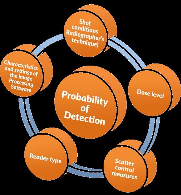
We will, similarly, take some risk with one equation that will be fundamental to explain several of the ideas discussed in this article. This equation, which explains the interconnection of three key image characteristics –brightness, sharpness, and noise – that have a profound effect on image quality (IQ), is as follows:
IQ = (brightness) X (sharpness) 2 (noise)
The equation explains that image quality: 1) is directly proportional to the brightness, which means that as brightness increases, within the limits that allow proper image interpretation, the image quality also increases, 2) is directly proportional to the sharpness but in this case, the value of sharpness is squared, which translates into a sensibly deeper impact of increased sharpness in image quality than the influence of brightness, and 3) is inversely proportional to noise, which translates that as noise decreases image quality improves in a linear form. In brief, as brightness and sharpness improve, and noise is reduced, the overall image quality improves.
A CR system includes the A) detector (imaging plate), B) the reader, C) a computer, its associated imaging processing software, D) and a monitor. The detector captures the radiation. The reader extracts the stored charge from the imaging plate by stimulating the phosphors with red laser light. The plate glows blue when the red laser strikes it. The blue light is collected and converted into a voltage signal that is then sampled and sent to the computer. The computer assimilates the voltage data into rows and columns that correspond to specific plate locations. The voltage signal is then mapped to various intensity levels for the individual pixels. Using specific software, the user then can view the analog representation of the digital image on a monitor. We strongly encourage the reader to review our white paper “Throwing light over Computed Radiography myths through sound and practical Imaging Plates
information” for more details on the elements that constitute a CR system.
There are some general guidelines that one can follow to obtain optimum CR image quality. For a given part, the radiographic technique and exposure conditions can closely match a film technique. Typically, a radiographer uses the minimum kV during exposure that penetrates the material to a specified thickness; this maximizes the contrast sensitivity. The mA (tube current) and time can be changed to modify the overall dose level needed. For radioisotopes, the source energy is fixed and the only thing that can be varied is the exposure time for a specific activity. With CR, the imaging plates are very responsive to dose. Therefore, the easiest way to improve image quality is to increase the dose. The system grey level response will be linear as a function of the dose level.
The selection of imaging plate type also determines image quality. Table 1 provides general guidelines for imaging plate selection based on energy levels and energy type used for a truly diverse set of radiographic techniques:
X-ray <80 kVp
Cobalt 60 Gamma Peaks at 1.17, 1.33 MeV
192
Seven peaks between 200 –600 keV
Nine peaks between 66 – 401 keV
Table 1: Imaging plate selection as a function of energy level and energy type, adapted from White [9].
General purpose (GP) imaging plates have lower resolution capabilities, but they are brighter and have slightly less noise. These plates typically are used for very high-energy applications or when image quality is not particularly critical. High resolution (HR) imaging plates offer the best combination of resolution, brightness and noise. These typically are used for applications where one desires the best possible image quality. Ultra-high resolution (UHR) imaging plates resolve fine detail because they have blue dye added to the phosphor layer to absorb the scatter from the red laser. However, they have reduced brightness and higher noise levels. These plates typically are used for lower energy applications and for materials that have less attenuation.
Another important attribute to control during CR exposures is Compton scatter. Scatter is the formation of longer wavelength, lower energy radiation as it
interacts with the material being irradiated. Computed radiography plates have high absorption at lower energy levels. Lead screens on the backside of the imaging plate typically are used to control scatter. Sometimes, a thin sheet of copper is placed between the lead and the back side of the imaging plate to block the fluorescence of the lead. When energy levels are high, typically above 200 kV, a front-side lead screen may be used for additional scatter control. Table 2 offers some suggestions to start exploring suitable alternatives of screens and radiographic techniques to minimize the effect of scattered radiation on image quality.
Energy Range Front Screen, inches Front Screen, mm
> 5MeV
> 1 to 5 MeV or Co60
0.020 to 0.040 Pb
Ir-192 or Se-75
< 1 MV and > 250 kV
< 250 kV and > 50 kV
< 50 kV and > 0 V
0.020 to 0.150 Fe, Cu or Pb
0.010 to 0.030 Fe or Cu, plus
0.3 to 0.8 Fe or Cu, plus 0.6 to 2.0 Pb
0.6 to 4.0 Fe, Cu or Pb
0 to 0.020 0 to 0.4
0 to 0.010 0 to 0.3
0 to 0.005 0 to 0.1
None
None
NOTE 1 – The screen thicknesses listed for the various energy ranges are recommended thicknesses, not required thicknesses. Other thicknesses and materials may be used provided the radiographic quality level is achieved.
NOTE 2 – Screens are Pb unless otherwise indicated.
NOTE 3 – Pb screens may be replaced completely or partially by Fe or Cu screens. The equivalent thickness for Fe or Cu is three times the thickness of Pb.
NOTE 4 – If necessary, the IP should be shielded from backscattered radiation by a sheet of lead of at least 0.010 in. [0.254 mm] thickness or a sheet of tin of at least 0.060 in. [1.5 mm] thickness, placed behind the IP. An additional shielding of steel or copper of 0.005 in. [0.127 mm] should be applied between the lead shield and the IP to reduce the influence of lead X-ray fluorescence radiation. No lead screens should be used in contact with the back side of the IP for radiation energies above 80 keV.
Table 2: Metallic Screen Recommendations for CR Imaging Processes, adapted from ASNT [1] and White [8].
ASTM E2033-17 offers specific guidance for Scattered Radiation Control in the following terms: “Metallic
screens (front, back, or both) or filters should be used as necessary to control scattered radiation from the floor, walls or other surrounding objects from interfering with the image or radiographic image quality requirements. Additionally, scattered radiation effects can be reduced by collimating the radiation beam as much as possible to the area of interest (AOI)”.
Between exposure and reading, imaging plates lose signal as a function of time. The signal loss is a result of photoelectrons recombining to non-useful energy states. The signal declines naturally as a function of time; this decay process is called dark decay. The signal also declines due to light fading, which is caused by handling bare plates in lighted room conditions between exposure and
scanning. Background lighting further stimulates the recombination of photoelectrons to non-useful energy states. The background lighting condition recommendation between exposure and reading is 2500 lux-seconds or less. To improve consistency, it is recommended to read the plate within five minutes after exposure. Implement IP manufacturer’s directives related to environmental conditions in the areas where IPs are handled and processed; this includes the selection of the adequate type of lighting and the use of protective gloves to maximize the IP lifespan, minimizing the possibility of artifacts due to inadequate handling.
The reader type and settings also determine image quality. The reader is an assembly of hardware, optics, and electronics. All readers have roughly the same functionality. The mechanism of image formation follows the process of photostimulated luminescence, whereby a red laser stimulates the phosphors in the imaging plate to emit blue light in proportion to the dose that was received. Important reader parameters that impact image quality are the pixel size selection, the laser intensity, and the spot size. Equilibrium is fundamental in choosing those parameters. A fundamental rule of thumb is to review, as a starting point, which values of these three parameters are commonly used in the industry for the CR imaging application you are attempting, within the acceptable ranges of the applicable CR codes, regulations and/or standards for the components you are analyzing, and from this starting point, use the suggestions included along the present white paper to improve image quality.
The analog representation of the digital image is displayed on a monitor. It is essential to always have in mind that image quality calculations are done on the captured data; not on the analog data from the monitor. Software is used to view and manipulate the image for viewing. Proprietary image processing can be performed to enhance either the display or the underlying data. The monitor should meet the required recommendations for brightness and contrast ratio suggested by the CR equipment manufacturer, and the image should
be viewed under the appropriate background lighting conditions and viewing distance as specified in ASTM E2033-17 paragraph 7.16.
Best practices of CR imaging processes using imaging plates
Hole or wire type image quality indicators are used to ensure that the appropriate contrast sensitivity is being met for individual exposures. ASTM E2445 specifies that the key image quality metrics are contrast sensitivity, basic spatial resolution, and signal-to-noise ratio. The contrast sensitivity is the minimum percent change in an object that produces a perceptible change in the image. A radiographer should discern the smallest possible difference in thickness in order to perceive defects (See Figure 2).
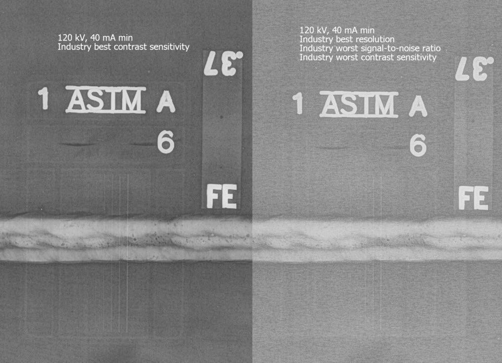
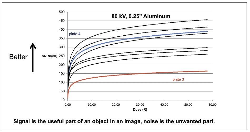
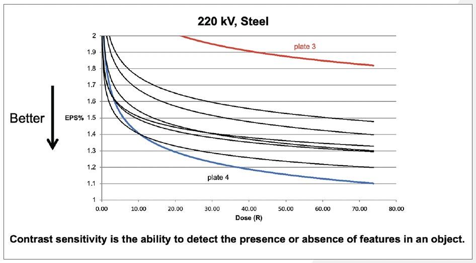
Typically, as described in ASTM E1647, we desire 2% contrast sensitivity or better for the material type that we are examining. The basic spatial resolution is a measurement of the amount of detail in the image, typically measured on an image of a duplex wire gauge. Better resolution (higher detail) is usually desired, though not always necessary. The basic spatial resolution is a function of the system pixel size, laser, imaging plate, and radiographic conditions. The signalto-noise ratio (SNR) is a calculation of mean pixel intensity divided by the standard deviation (noise) of a region of interest.
Figure 3 illustrates the signal-to-noise ratio normalized to a basic spatial resolution of 80 μm (SNRn(80)) as a function of dose level for an HR plate in a typical CR system. As the dose is increased, the normalized SNR rapidly improves and then levels off. The plate in Figure 1 was exposed at 80 kV and the SNRn(80) was plotted for a 0.25” thickness of aluminum.
Figure 4 illustrates the equivalent penetrameter sensitivity (EPS) contrast sensitivity as a function of dose level for an HR plate in a typical CR system. The EPS technique for determining an estimate of contrast sensitivity is described in ASTM E2446. As the dose is increased, the contrast sensitivity rapidly improves and then levels off.
Imaging artifacts are another aspect of examination that radiographers have to contend with. ASNT’s Nondestructive Testing Handbook, Fourth Edition, Volume 3 - Radiographic Testing defines Artifacts or false indications as (1) Test indications that could be interpreted as originated from a discontinuity but that actually originates where no indication exists, and (2) Indications due to misapplied or improper testing. By its definition it is evident that all NDE methods and techniques are subject to be affected by false indications, therefore imaging artifacts may be present in radiographic images, regardless if the recording media is film, imaging plates or DDAs, and generate the need of repeating certain images where artifacts interfere with image interpretation. Artifacts are caused by the interaction of the reader’s laser with the imaging plate surface. Artifacts are typically
white in the radiographic image because they are light blocking. Ideally, an imaging plate would have sufficient durability to allow for repeated use without imaged artifacts. An imaging plate is no longer usable when a radiographic artifact can potentially hide an indication, therefore rendering the plate unsuitable. The number of achievable use cycles is dependent upon the operating environment and the user’s tolerance for artifacts. Protective overcoat technology is the primary driver for improved imaging plate lifetime.
Durability relates to the material physical properties of the imaging plate; specifically, the material properties of the overcoat that protects the phosphor layer.
Scratch and abrasion resistance, dust repellency, the ability to clean, moisture and chemical resistance, crack avoidance, and edge integrity are examples of durability attributes. Scratches and abrasions both create radiographic image artifacts, but they form differently.
Scratches form from very fine localized pressure dragged across a prescribed distance. Figure 5 utilized a 47º conical sapphire stylus with a 62.5 μm radius conical tip to create the scratches. Constant loads of 3, 5, 10, 25, and 50 g were applied to create the scratch tracks. Loads less than 25 g did not image in the flat field radiograph.
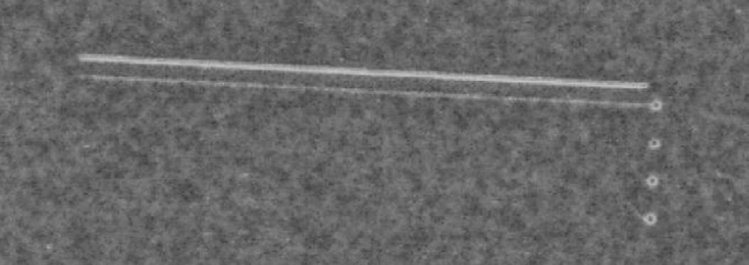
Dust particles can become attracted to the surface of a plate. The particles will cause the red laser to deflect, or will block blue light, which shows as tiny white spots in the image. The best way to manage dust particles is to use an electrostatic roller to clean the plate surface prior to scanning. The ability to clean the surface is important in order to remove dirt or debris that may form over time. Another source of artifacts can be moisture or oxidizing chemicals. The phosphor contains iodide, which can be converted to iodine. Iodine is yellow and blocks blue light, which manifests as image artifacts. Water, peroxides, and ozone gas can form artifacts in contact with the imaging plate surface. Cracks or edge chipping can result in artifacts; however, plates are designed to minimize these cracking and chipping issues.
There are usage criteria and guidelines for maximizing imaging plate lifetime. When not in use, store plates flat in dark and dry conditions. Handle them by the edges and use cloth gloves if desired. Do not crease or kink the plate because this will form a permanent
and irreversible crack. Avoid extreme humidity and or wet conditions when using an imaging plate. Avoid surface temperatures greater than 212 °F (100 °C); and use plates in the temperature range of –22 to +120 ºF (–30 to 49 ºC). For surface cleaning, use only the manufacturer-recommended cleaner with a lint-free cloth. In customer use situations there are handling guidelines that maximize plate lifetime. Avoid sliding the plate surface against abrasive materials. For high energy conditions such as iridium radioisotopes that require front side leads, completely open the cassette before insertion or removal of the plate. Do not remove the protective overcoat of the lead, as lead dust on the plate surface will form imaged artifacts.
Where can I innovate in my everyday work?
Guidelines to achieve optimum CR image quality.
The importance of having sufficient dose on the image capture media or device (regardless if it is film, imaging plate, DDAs) to obtain optimum image quality cannot be overstated: Dose is it at the core of the imageforming signal received. Without sufficient dose, the remaining inherent noise in the system becomes an ever-increasing part of the final image. Noise is nonimage-forming signal and, in consequence, it is not a radiographer’s friend. Admittedly, in NDT applications, exposure times may be long and sometimes this is perceived as having a negative impact on the process productivity, but it is shortsighted to under-expose an object to end up with less than optimum quality in the resulting images. To support key decision-making processes and actions, image quality is what matters. Table 3 compiles key elements that can have a positive impact on your everyday CR imaging practices using IPs:
Summary of the key ideas in this White Paper
Remember that sharpness is not the best indicator of image quality; IQ is a function of brightness, sharpness, and noise; all three work together.
Imaging plate selection, dose level, and scatter control determine the radiographic image quality for computed radiography.
Plate handling and use determine the artifact level in the radiograph as a function of time; this results in how many use cycles can be achieved.
Follow best practice guidelines above to maximize the overall image quality and the number of imaging plate use cycles.
Good radiographs are images that are free from artifacts!
IPs should be handled as gently and carefully as possible, taking care not to scratch or contaminate them, which means also proper handling, cleaning and maintenance of CR cassettes and screens. If you follow the following guidelines, IPs can easily provide the expected plate life for the customer and be utilized for many cycles.
Regularly clean the IP using a dry soft, lint-free cloth, such as a microfiber towel; if soil cannot be removed by dry wiping, use manufacturer’s approved IP cleaning materials.
After wet wiping, lightly wipe the IP with a soft, dry cloth. The IP must be dried completely before being reloaded into a cassette.
General guidelines to handle IPs
It’s critical to handle IPs with care to avoid damaging them. Avoid using plastic erasers or any solvents that are not approved, and refrain from using your fingernails to scratch or dig into the surface of the IPs.
IPs should be handled in such a way to avoid crimping. Do not bump IPs against other objects and do not drop them onto the floor or the top of a table. Anything that blocks light at the surface of the IP will manifest as white spot artifacts in the image.
An imaging plate is no longer usable when an artifact can potentially hide an indication in the radiography’s zone of interest.
The number of use cycles for the IP is determined by the artifact level and the tolerance for artifacts.
When IP artifacts, such as crimp marks, scratches, or others, cause the IP to be unusable, the IP should be removed from service and disposed of in accordance with the manufacturer’s recommendations. Most IPs will have a Material Safety Data Sheet (MSDS) available from the manufacturer.
Guidelines to achieve optimum CR image quality
The CR radiographic technique can closely match the film technique. The best way to improve image quality is by increasing dose.
Scatter must be controlled to achieve the best possible image. The pixel intensity must be related to an image quality level. Select the proper imaging plate for your application.
Store IP in dark and dry conditions; avoid extreme humidity or wet conditions.
Guidelines to prevent artifacts in Computed Radiography Imaging Processes
Handle by the edges and use gloves to avoid fingerprints; use manufacturer-recommended cleaner with a lint-free cloth.
Do not crease, kink, or drag across surfaces. Avoid surface temperatures > 212 F (100 C)
Temperature range for use; -22 F (-30 C) to 120 F (49 C)
Completely open flexible cassettes before insertion or removal of a plate when front side leads are used.
Table 3: Best practices in Computed Radiography Imaging Processes, adapted from White [7] [8].
How you can use the information of this document in your everyday activities
For our readers interested in exploring how computed radiography (CR) can be integrated to your processes please visit: www.carestream.com/en/us/ nondestructive-testing-ndt-solutions
Here are some supplementary information resources from Carestream’s products and services portfolio: Products Featured
• INDUSTREX HPX-PRO Digital System
• INDUSTREX HPX-1 Plus Digital System
• FLEX GP, FLEX HR and FLEX XL Blue Digital Imaging Plates
• INDUSTREX Digital Viewing Software
Training Services
• Advanced Industrial Radiographic Training Academy
Computed Radiography - 40 Hour Online Course Digital Imaging - 40 Hour Classroom Training
Resources from ASNT
• Nondestructive Testing Handbook, fourth edition: Volume 3, Radiographic Testing: source.asnt. org/1pekc1o/
References
1. ASNT, (2019). Nondestructive Testing Handbook, fourth edition: Volume 3, Radiographic Testing, Chapter 8, Pages 259-276 Columbus, OH, American Society of Nondestructive Testing.
2. ASTM (2022), ASTM E1316 – 22, Standard Terminology for Nondestructive Examinations, West Conshohocken, PA, ASTM International, 2020.
3. ASTM (2022), ASTM E1647-16, “Standard Practice for Determining Contrast Sensitivity in Radiology,” ASTM International.
4. ASTM (2017), ASTM E2033-17, “Standard Practice for Radiological Examination Using Computed Radiography,” ASTM International.
5. ASTM (2020), ASTM E2445/E2445M-20, “Standard Practice for Performance Evaluation and Long-Term Stability of Computed Radiography Systems,” ASTM International.
6. ASTM (2015), E2446-16, “Standard Practice for Manufacturing Characterization of Computed Radiography Systems,” ASTM International.
7. White, B., (2015) Article “ Imaging Plate Use for Radiographic Nondestructive Evaluation” ASNT 2015 Annual Conference.
8. White, B., (2015) Presentation “Imaging Plate Use for Radiographic Nondestructive Evaluation” ASNT 2015 Annual Conference.
35th Annual Conference and Exhibition on Non-Destructive Evaluation (NDE 2025)
11 to 13 December 2025 | Mumbai, India
This event is a vital platform for professionals, researchers, academicians and industry leaders to come together and exchange ideas, innovations and advancements in the ever-evolving domain of NDE. In line with the theme of the Conference, ‘NDE Empowering Industrial Excellence’, sessions will cover various sectors, including oil and gas, energy, metals, materials and manufacturing. NDE 2025 will feature a blend of technical presentations during scientific and industry sessions, plenary and keynote addresses, interactive sessions and a state-of-the art exhibition.
For further information, visit: isntnde.in
Latin American Workshop on Structural Health Monitoring
7 to 9 January 2026 | Santiago, Chile
Following the success of the inaugural LATAM-SHM in Cartagena, Colombia, in 2023, this event will be hosted by the Faculty of Physical and Mathematical Sciences at the University of Chile. The workshop aims to facilitate the exchange of information and to highlight the latest advancements in structural health monitoring technologies and their practical applications, focusing on contributions and developments from Central and South America. An exhibition space will also be available for product and technology demonstrations.
For further information, visit: latam-shm2026.cimne.com
NDTMA 2026 Annual Conference
19 to 19 February 2026 | Las Vegas, USA
The Non-destructive Testing Management Association (NDTMA) brings together top level speakers on NDT Management topics such as leadership, marketing, insurance, mergers and acquisitions, education, apprenticeship, certification, standards, and regulatory topics as well as presentations on emerging technologies and trends in the NDT industry. Plus, see the young professionals program and new awards program for innovation and advocacy. Decision makers in the NDT world all come together at NDTMA to learn best practices and collaborate to help the NDT industry thrive.
For further information, visit: ndtma.org
20 to 22 April 2026 | Newcastle, Australia
The 2025 AINDT Summit will bring together industry leaders, innovators, and NDT professionals for three days of knowledge sharing, networking, and professional development in Newcastle from 18 to 20 November 2025. With the theme The Power of Inspection, the Summit will explore how inspection services deliver crucial insights about critical assets across industries. This timely theme also addresses Australia's evolving energy landscape and the expanding role of inspection services in supporting our future energy infrastructure.
For further information, visit: aindt.com.au
The 17th Asia Pacific Conference for Non-Destructive Testing (APCNDT)
11 to 14 May 2026 | Hawaii, USA
APCNDT is set to be an unmissable event for NDT professionals across the globe. Held under the theme Breaking Barriers: NDT Solutions for a Changing World – Innovate, Adapt, Transform, this premier conference will showcase the latest innovations and emerging technologies that are redefining non-destructive testing. Attendees will have the opportunity to connect with global experts, share knowledge, and explore new solutions to address the evolving challenges faced by industries worldwide. Join us to discover how NDT is driving transformation, and paving the way for a dynamic future.
For further information, visit: apcndt2026.com
The 14th European Conference on Non-Destructive Testing (ECNDT 2026)
15 to 19 June 2026 | Verona, Italy
ECNDT 2026 is a leading international event hosted by the European Federation for Non-Destructive Testing. Bringing together experts, researchers, and professionals, the conference is a hub for sharing innovation, research, and emerging technologies shaping the future of inspection and quality assurance. The program features technical presentations and case studies across a range of sectors, complemented by a dynamic exhibition. This connection between research and practical application encourages collaboration, networking, and advancement of NDT worldwide.
For further information, visit: ecndt2026.org


ASG NDT Supplies is a provider of NonDestructive Testing (NDT) equipment and supplies, catering to various industries that require reliable testing solutions without causing damage to materials. Founded with a commitment to quality and innovation, ASG NDT Supplies aims to serve sectors including aerospace, maintenance, Utilities, manufacturing, and construction.

Do you have a radiographic quality control or NDT inspection application that requires constant monitoring or operates in an environment where cooling is an issue? For many applications, a conventional tube head with air cooling and intermittent operation might be sufficient. However, for higher use applications or hotter operating conditions, the number of exposures you can achieve could be limited by the ability to cool the tube head and duty cycles.
Comet offer a range of water-cooled tube heads that are ideal for continuous monitoring or operating in environments where a good supply of cooling air is a problem. These solutions can also futureproof your workflow when higher levels of inspection are required. Their hybrid cooling concept makes them the perfect answer for integrating into 24/7 production lines, installation into confined spaces with compromised air
Active in the NDT industry since 1978, Charlie Panos has over 40 years of experience. He provides
International Tube Testing (ITT) was established by Charlie Panos in 2000. With over 40 years of industry experience, Charlie has in-depth expertise and qualifications in the engineering, testing and inspection industry.
ITT was formed to fill a growing need for accurate, dependable specialised engineering testing services. ITT provides specialised IRIS and RFT tube testing and has tested almost every boiler design in the process,
ASG is aligned with industry global manufacturers, enabling us to offer a comprehensive range of NDT products and accessories.
ASG NDT Supplies prides itself on its deep understanding of the NDT market and its dedication to providing customers with top-tier service. ASG consists of experience and the knowledge within the NDT Industry to offer expert advice, tailored solution packages to meet any customers requirements.
For more information, visit: asgndtsupplies.com
flow, or extremely hot operating environments.
Comet’s water-cooled systems range from 160kV to 300kV in standard (3.0mm) and small focal spot (1.0mm) options to suit most applications. If you have ever used a Comet EVO (or Yxlon SMART EVO) series of tube heads, they all share the same user interface that you are already familiar with.
These systems belong to the EVO family of tube heads that won the Red Dot design award when they were launched. This includes features such as highperformance metal-ceramic X-ray tube, lightweight composite casing and IP65-rated enclosures that marry together to bring performance, reliability and robustness.
For further information, visit: www.axt.com.au/ products/comet-evo-series-ndt-tube-heads/ or contact info@axt.com.au or (02) 9450 1359.
petrochemical and power industries in Australia, the Pacific Islands, Papua New Guinea, Indonesia, Malaysia, Philippines and India.
The company can test tube sizes from 16mm up to 200mm, including straight tubes and tubes with bends for industries as diverse as pulp and paper, fabrication, maritime and aerospace.
ITT prides itself on delivering personalised, ethical service every time and has the field proven experience, technology and determination to ensure all your requirements are exceeded.
For further information, visit: tubetesting.com.au
Established in 1992, NDT Equipment Sales is a leading supplier of equipment and consumables for all methods of non-destructive testing, including gamma radiography, digital radiography magnetic particle and dye penetrant testing, ultrasonics and eddy current testing, amongst others.
NDT Equipment Sales is the sole Australian agent for QSA Global, also agents for Golden Engineering, NOVO, Sentinel, Parker Research Corporation, Elektrophysik, Wilnos, Automess, Rohmann, SIUI, Diverse Technologies.
OMS is the only all-in-one NDT business management software, verified for vulnerability, and boosted with AI (Augmented Intelligence) advanced LIMS to manage Laboratory’s Operations Management Systems as per ISO 17025, ISO 17020, NATA, ISO 9001.
OMS executes mundane repetitive tasks, 24/7 for NDT, inspection, metallurgy, mechanical and chemical testing and hydro pressure testing. The system can generate one-click reports instantly, complying with standards and NATA, and without transcription errors. It facilitates secure signing of reports, and emails without an external email program.
OMS includes automation for accounts book-keeping, timesheet, productivity reports, auto-debt collection, assets and calibration, staff inductions and certificates, document SharePoint, CRM, quotations, and more.
Russell Fraser Sales (RFS), a leading supplier of Non-Destructive Testing (NDT) and inspection equipment, is proud to announce they have recently joined the Cebeco Group — strengthening their position as Australia’s trusted partner in NDT solutions.
For over 30 years, RFS has been delivering reliable, high-performance inspection tools to professionals in mining, construction, oil and gas, defence, and manufacturing. Their product range includes ultrasonic flaw detectors, thickness gauges, magnetic particle
We are proud to announce that we have just been awarded distributor status in Australia for Labino NDT, global leaders in the design and manufacture of highquality UV-A lamps. We are optimistic that this new partnership will allow us to not only continue, but to enhance our capability to supply the NDT industry with high quality, reliable equipment.
For more information on the Labino range, please visit our website at www.ndt.com.au and type Labino into the search bar. Alternatively, please call our friendly team on (02) 9524 0558 to discuss your UV-A requirements.
OMS can save companies up to $200,000 per annum per branch by eliminating most IT hardware (computers, servers, laptops), software (Windows, MS Office, Antivirus) and human resources cost, NCRs, QA and rework cost.
OMS saves you time by eliminating data entry multiple times, by replacing several fragmented generic apps, at the cost of one coffee per day. It provides continuous automation and addition of features at no extra cost by 33 programmers and subject matter experts. Plus, OMS doesn’t charge any upfront cost for implementation, customisation or training, and there are no lock-in contracts, and zero exit fees.
OMS includes customised modules for VT, MT, PT, ET, RT, RTT, UT, UTT, PAUT, TOFD, Vacuum box, VI, PVI, Tank, Weld Supervision, Coatings, Hydro, PMI, CA and all mechanical testing. Since 2009, OMS is validated for over two million use-hours.
Email: systems@omssoftware.com.au to learn more.
inspection, visual testing tools, and more — all backed by expert advice and dedicated support.
Now, as part of the Cebeco Group, they are expanding their capabilities while continuing to provide the same personalised service and technical expertise their customers rely on. RFS is still your go-to source for top brands like Olympus, Cygnus, and Waygate Technologies, with the added strength of a larger, nationally integrated network.
Whether you're in the field or in the lab, Russell Fraser Sales helps you inspect with confidence.
Explore our range at www.rfsales.com.au or call (02) 9545 4433 to speak with an NDT specialist today.

Smartchem Industries is your trusted partner for magnetic particle and dye penetrant requirements, with over 100 years’ combined experience in the manufacture and distribution of magnetic particle and dye penetrant consumables.
Smartchem is 100% Australian owned and proudly manufactures in Australia with Australian resources where possible. Smartchem prides itself on service, both technical and in the delivery of their products.
The Smartcheck MPI range complies with the requirements ISO-9934.2 and other relevant standards. The Smartcheck dye penetrant range has been third party type tested to ISO 3452.2 by MPA Hanover in Germany, including Smartcheck Dye Pen Fluoro—a level
3 water washable/solvent removable fluorescent dye penetrant. All CoC and SDS are available on the website which is a useful reference tool for an audit or where a copy is required in the field.
SmartChem is the exclusive distributor for the Matcon range of magnets and equipment. They are also exclusive distributors for Promag UV lights and equipment.
SmartChem supplies direct and has a comprehensive network of resellers. Heatleys Safety and Industrial (heatleys.com.au) are their exclusive distributor in Western Australia, while Accurate Instruments (accurate. kiwi) cover both the North and South islands in New Zealand. For distributors on the east coast of Australia, contact Smartchem direct.
Quality products and service at a reasonable price, that’s the Smartchem difference.
For further information, visit: smartchem.com.au