

INDUSTRIAL
THE OFFICIAL JOURNAL OF THE AUSTRALIAN INSTITUTE FOR NON-DESTRUCTIVE TESTING
RADIOGRAPHY ULTRASONICS EDDY CURRENT PENETRANT MAGNETIC PARTICLE
VIBRATION ANALYSIS LUBRICATION ANALYSIS THERMOGRAPHY ACOUSTIC EMISSION
Inspection starts

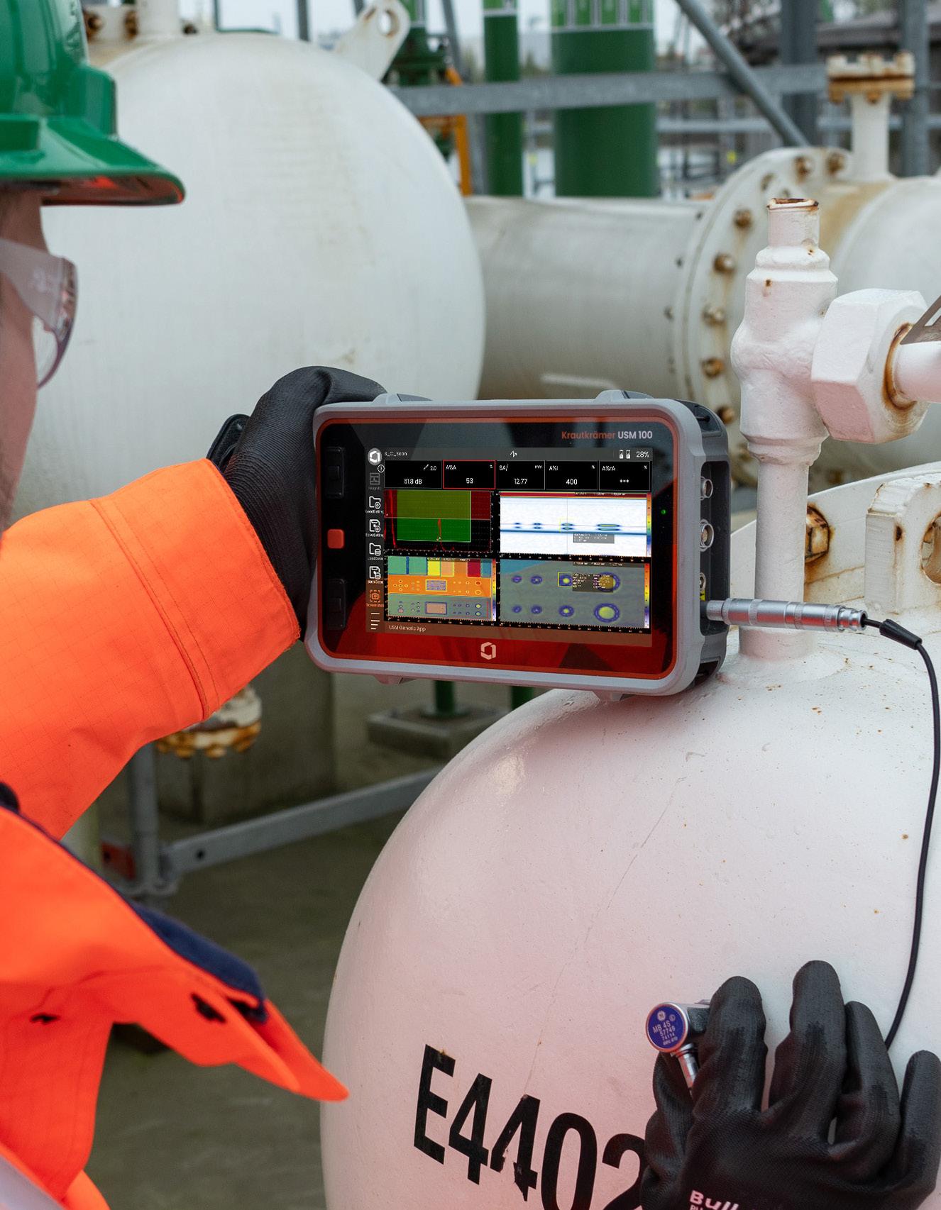
• App integration
• Guided calibration for quick setup
• IP 67 rating to withstand toughest conditions
• Advanced and customizable Data Recorder
• Encoded B/C scan capability
Krautkrämer USM 100 continues to deliver unparalleled performance and reliability - at a competitive price.

President's Message
Over the past 12 months, the Board of Directors and CEO, guided by a recommendation from the 2023 Federal Council Meeting have undertaken a comprehensive review of the AINDT’s governance and procedural frameworks.

This initiative reflects our ongoing commitment to ensuring that the Institute’s structure remains robust, accountable, and aligned with best practices in the not for profit sector.
To achieve this objective, we enlisted the services of independent expert consultants to perform thorough evaluations of our governance and procedural standards. The Governance Review, led by Governance by Design, has been particularly instrumental in identifying opportunities to enhance clarity in roles, strengthen decision making processes, and ensure compliance with our legal obligations.
The findings of this review were discussed at the Federal Council Meeting in November last year. It was during these discussions that the Federal Council reaffirmed, almost unanimously, the critical importance of preserving the federal model, where each state branch plays a direct role in shaping the direction of the Institute. This model, and the voices of our members across Australia, are at the heart of our strength.
On the Council’s recommendation, the Board has endorsed the proposed ‘Improved Architecture’ model put forward in the independent Governance Review. This model forms the foundation of our path forward.
The governance review report emphasises the need for clear, practical governance aligned with not for profit principles, and specifically highlights the following priorities:
• Clarification of roles and responsibilities.
• Stronger legal and strategic alignment across governance bodies.
• More cohesive and effective Board operations.
• Development of key frameworks, including a new Constitution, a Board Charter, Certification Board By-Laws, and formal Delegations of Authority.
These reforms are not simply structural, they are designed to ensure that AINDT continues to serve its mission with professionalism, transparency, and member driven accountability.
In parallel, a review of the AINDT Quality and Procedures Manual (QPM) revealed that our current documentation is somewhat outdated, fragmented, and inconsistent. Recommendations from the QPM report include:
• Consolidation into a unified Quality Manual.
• Clearer formatting, structure, and language.
• Implementation of document control and regular audits.
• A stronger alignment with AINDT’s vision and certification services.
These changes will provide for better consistency, support the new Certification Services Manager and improve overall compliance and operational clarity.
As a result of these reviews, we are now undertaking a full revision of the AINDT’s Constitution and operating procedures. This will ultimately require a vote from our membership to adopt the proposed new Constitution and By-Laws.
To guide this effort, a Constitution Review Committee has been established. Their terms of reference include:
1. Ensuring compliance with Australian Corporations Law and relevant legislation.
2. Aligning recommendations with the independent Governance Review.
3. Seeking professional legal and governance advice.
4. Acting in the best interests of members, informed by consultation feedback.
5. Maintaining the integrity of our NDT and CM Certification schemes.
This process will be transparent and consultative. The Committee and Board of Directors are committed to keeping all members well informed as we move forward.
I look forward to updating you all on the committee's progress towards a comprehensive constitution and by-laws that serve every member's interests.
Warm regards, Joshua Morris, President Australian Institute for Non-destructive Testing
Joshua Morris

President: Mr Joshua Morris
Immediate Past President: Mr Ian Hogarth
Vice President: Mr Angelo Zaccari
Treasurer: Mr Glen Haberl
Secretariat Liaison: Mr Samual Hallifax
CEO: Mr Stuart Norman
President Mr Frank Galea
Vice
Treasurer Mr Paul Ashby
Secretary Mr Matthew Thompson Official
Production Sally Wood Design Alarna O’Connell
AINDT
PO Box 52, Parkville Vic 3052
P: (03) 9486 9267
www.aindt.com.au
E: federaloffice@aindt.com.au
ADVERTISING
AINDT Federal Office
P: (03) 9486 9267
E: sally@wordly.com.au
INSTRUCTIONS TO AUTHORS OF TECHNICAL ARTICLES
Manuscripts should be submitted in electronic form:
1. in word
2. typed with single spacing
3. with figures as tif or jpeg files at better than 300dpi
Manuscripts should include:
1. symbols and abbreviations conforming to recognised standards; metric units (SI)
2. references listed, after the text, in the order in which they occur in the paper
3. references indicated in the text by arabic numerals in square brackets
4. tables and figures numbered separately but consecutively with Arabic numerals and brief, descriptive titles
5. a reference in the text to all tables and figures
6. graphs and diagrams made with lines of sufficient thickness to reproduce well
7. titles and address of authors
Procedure for submission of manuscripts:
1. articles should be sent to: journal@aindt.com.au
2. manuscripts will be submitted to referees who will remain anonymous
3. reprints of each paper will be supplied free to the author
Published by: The Australian Institute for Non-Destructive Testing, PO Box 52, Parkville, Vic 3052 Australia
ISSN: 2203-2940
A Message from the CEO

Looking Ahead: Opportunities in Queensland’s Energy Sector
As the peak body for Non-Destructive Testing (NDT) and Condition Monitoring (CM) in Australia, AINDT welcomes the Queensland Government’s recent decision to open nine new areas for gas exploration. This initiative signals a promising future for energy development—and by extension, for the NDT and CM professionals who ensure the safety and reliability of infrastructure in this sector.
Queensland’s growth brings with it an urgent need to address the national skills shortage. Despite being vital to the nation’s safety and productivity, the NDT industry has operated for over 50 years with no government-funded training programs, relying instead on industry self-regulation and certification.
The result has been world-class safety outcomes—with few major incidents—but the system is under increasing pressure.
There is now a clear opportunity for partnership with the Queensland Government. AINDT is working to secure a meeting with government representatives to discuss how we can work together to:
• Increase the number of certified NDT technicians in Queensland
• Build a skilled pipeline of talent to support future energy projects
• Position Queensland as a centre of excellence for NDT, exporting skills, knowledge and innovation globally
With targeted support, the state can become a national— and even global—leader in NDT excellence, exporting talent and innovation to support safer, more sustainable energy outcomes.
Strengthening Our Institute: Governance, Growth and Member Support
I’d like to extend my sincere thanks to the entire AINDT membership for the support provided to me during my first year in the role. Having worked with five other industry bodies in the past, I continue to be amazed by the number of individuals and organisations who so willingly give of their time to strengthen and support the Institute.
Over the past year, AINDT has continued its focus on operational improvement and forward planning. Our independent governance review led to the formation of a Constitutional Committee, which is currently reviewing recommendations to present at the 2025 AGM. Meanwhile, the implementation of our new database and website marks a major step forward in modernising our systems.
We’ve also lodged our application for ISO 9712:2021 accreditation with JAS-ANZ and remain optimistic about its approval. I extend my sincere thanks to all volunteers who contributed to this body of work.
The AINDT has worked hard to keep membership fee increases to a minimum, even as we enhance our governance and operational performance. We also recognise the cost of living pressures that the country is facing. In light of this, the Board of Directors has resolved not to increase membership fees for the 2025/2026 financial year.
Your membership is tax deductable, and we look forward to working together to further improve the AINDT and its services. Renew your membership today.
Stuart Norman
Don’t Miss Out: AINDT Summit 2025 Early Bird Tickets Close 30 June
Preparations are well underway for the AINDT Summit 2025, taking place in Newcastle, New South Wales from 18 to 20 November. This major event on the AINDT calendar will bring together professionals across NonDestructive Testing (NDT), Condition Monitoring (CM), and Inspection for three days of learning, collaboration, and connection.
Whether you’re a seasoned technician, an industry leader, or a new practitioner, the
In addition to the technical program, the Summit provides ample opportunity to network and reconnect. Join us at the Welcome Reception in the exhibition hall on Tuesday 18 November from 6.00pm, or celebrate with colleagues at the Gala Dinner on Wednesday evening—an event not to be missed.
We’re thrilled to announce that the Gala Dinner will be hosted by none other than Lehmo—one of Australia’s most recognisable and well-travelled comedians.
Known for his appearances on ABC’s Utopia, Network Ten’s The Project, and radio stations around the country, Lehmo brings sharp wit, charm and plenty of laughs

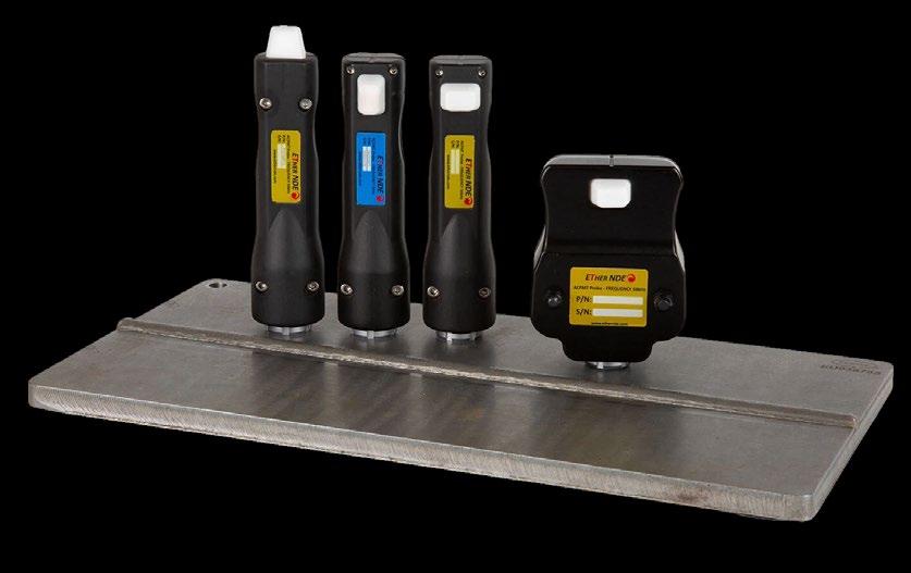
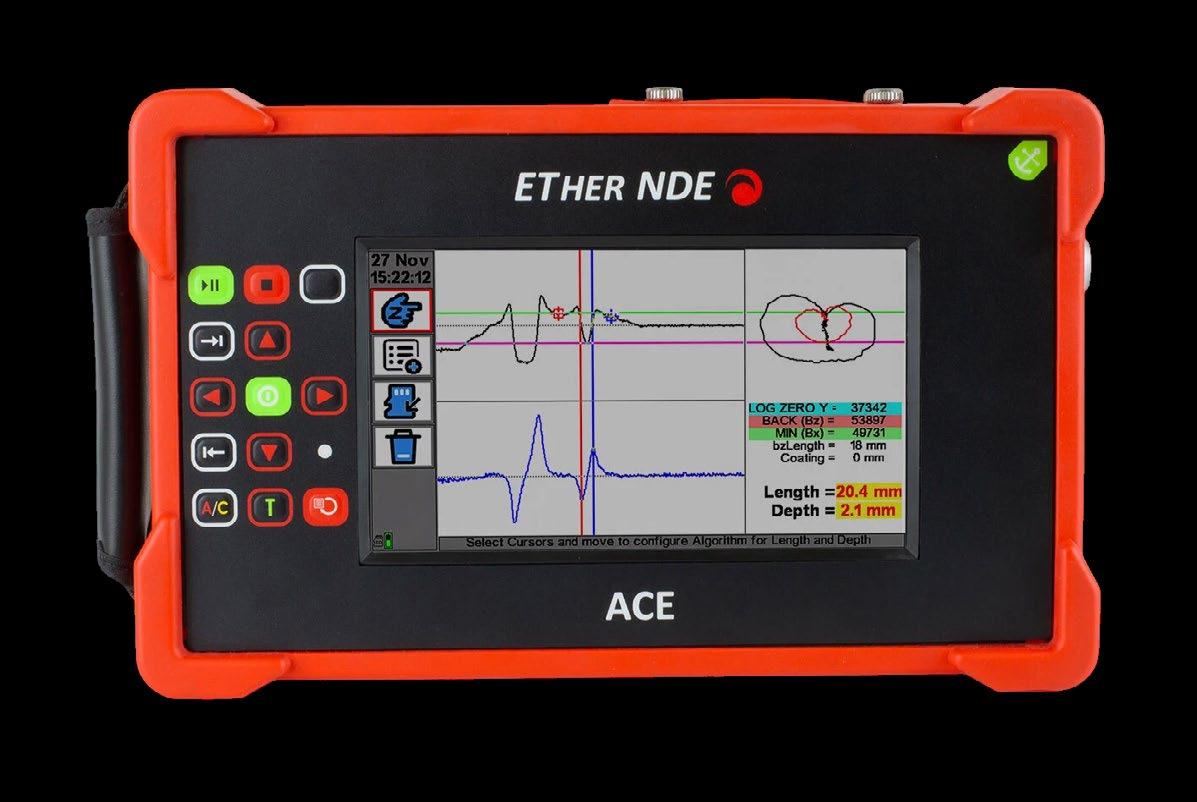
The "ACE" provides the end-user all the functionality and advantages of Alternating Current Field Measurement Technology (ACFMT) NDT inspection, in a lightweight, rugged instrument; available with a selection of standard probe designs, developed and manufactured in-house at ETher NDE


ETher NDE's ACFMT instrument, the "ACE"
UNTIL 30 JUNE


EARLY BIRD TICKETS >
T H E P O W E R O F I N S P E C T I O N 1 8 - 2 0 N O V E M B E R 2 0 2 5 N E W C A S T L E C I T Y H A L L

AINDT Summit 2025: The Power of Inspection
The AINDT Summit 2025 will bring together industry leaders, innovators, and NDT, CM and Inspection professionals for three days of knowledge sharing, networking, and professional development in Newcastle from 18 to 20 November 2025.
Early
Bird
Deadline Approaching
Register for the 2025 AINDT Summit before 30 June and save with early bird pricing!
Join industry leaders, innovators, and hands-on practitioners from aerospace, defence, infrastructure, manufacturing, and more.
The Summit is designed to inform, inspire, and ignite conversations across the NDT and condition monitoring community — with keynote presentations, technical sessions, and panel discussions that tackle the latest trends and challenges, including:
• Technical papers that cover the latest developments in technology and trends and real world case studies from leading experts
• Face to face Q&A and panel sessions with industry leaders
• Hands on access to the latest developments in technology and trends at the exhibition
• Practical takeaways and valuable networking
Lock in your registration before 30 June to take advantage of early bird pricing and guarantee your spot.
aindtevents.eventsair.com/aindt-summit-2025/ register
Announcing the Host For the Gala Dinner
Join us for the highlight of the Summit social calendar— the AINDT Gala Dinner. This elegant evening of fine dining and entertainment celebrates the achievements of the NDT and condition monitoring community.
The Gala Dinner will be hosted by one of Australia's most loved comedians. You've heard him on the radio and seen him on Network Ten's The Project and ABC's Utopia: Lehmo!
Lehmo is one of Australia's most experienced and welltravelled comedians. His live work has seen him headline at comedy clubs for well over fifteen years and work all corners of the globe – USA, UK, Ireland, South Africa, Singapore, Malaysia, Hong Kong and Thailand.
Lehmo has also become Australia's number one combat comic', having completed seven tours of duty' performing for our troops abroad. These tours have seen Lehmo perform in army bases in East Timor, Iraq, Kuwait, UAE, Afghanistan, Egypt, Qatar and on a number of naval ships around the world.

Call for Papers
Have a new idea, case study, or innovation to share? Submit your abstract for the 2025 AINDT Summit, happening 18–20 November in Newcastle, NSW.
This year’s theme — The Power of Inspection — explores how testing powers detailed asset insights and drives industry innovation. We’re calling on researchers, practitioners, and industry experts to present original papers across NDT, condition monitoring, aerospace, and more. Topics include ultrasonics, radiography, eddy current / electromagnetic, thermography structural health monitoring and more.
By presenting the AINDT Summit, you can:
• Showcase new techniques
Share real-world case studies
Help shape the future of the industry
• Take advantage of 50% off registration for presenters
• Get exposure to industry leaders and wider industry in general
• Earn additional development points towards certification
Don’t miss the chance to present to Australia’s NDT, CM, and Inspection community. Submit your paper today! aindtevents.eventsair.com/aindt-summit-2025/ present
Member List
June 2025
The AINDT is a national peak body that promotes the professional practices of non-destructive testing and condition monitoring personnel. Our mission is to provide members, industry and the community with independent and professional service in relation to the science and practice of non-destructive testing.
Through the work of our state branches and federal office, AINDT is committed to fostering a community of professionals and organisations dedicated to the fields of non-destructive testing, engineering, and materials and quality testing.
We offer a tiered membership structure, inviting businesses to enhance their professional standing and industry influence by becoming a Company, Corporate, or Sustaining member. Our memberships unlock a suite of benefits, including marketing opportunities, heightened support, streamlined staff certification management, and much more. AINDT would like to thank the companies below for their valued support.
SUSTAINING MEMBERS
ATTAR
D R May Inspections
EnerMech
SRG Industrial Pty Ltd
Intertek
SUPPORTING MEMBERS
Chevron
COMPANY MEMBERS
NSW
ARL Laboratory Services Pty Ltd (Yennora)
AXT Pty Ltd
Barry Evans Lifting World
Bluescope Steel (Port Kembla)
ENDETEK
Hot Engineering
HVT Inspection Services
Magnetic Analysis Aust Pty Ltd
NBQC & Inspections Services
NDT Equipment Sales Pty Ltd
Nobel Engineering Services
Reliance Hexham
RPG Australia
Russell Fraser Sales Pty Ltd
Simplifi Nii P/L
SmartChem Industries Pty Ltd
Sonix NDT Pty Ltd
Thermal Imaging Services (AUS)
QLD
AXS Pty Ltd (Mackay
CORPORATE MEMBERS
Azure NDT Quality Services Pty Ltd
Bureau Veritas Australia
Chemetall (Australasia) Pty Ltd
Evident Australia Pty Ltd
GFS NDT
Hofco Oilfield Services
IRISNDT
OMS Engineering Pty Ltd
SafeRad SE Asia Pty Ltd
School of Engineering
TR Pty Ltd
Equipment Direct International Pty Ltd
Industrial Mining Inspection Solutions
International Tube Testing Pty Ltd
Metal Testing Pty Ltd
M-Test Mackay Pty Ltd
Queensland Alumina Limited
Testing Inspection and Calibration Services
VIC / TAS
ABEN Technical Services
ATCL
Defence Science and Techology Organisation (DSTO – Fishermans Bend)
Gippsland NDT Services Pty Ltd
Global Inspections & Engineering Services Pty Ltd
ITest NDT
LMATS Pty Ltd (Williamstown)
NATA
OMS Software Pty Ltd
SA / NT
ASC Pty Ltd
Kuzer Technical
QMS
Red Earth NDT Pty Ltd
WA
Alliance Solutions Group
Applecross Electrical & Testing Service
Asset Reliability Inspections Pty Ltd
Assurity NDT & Consulting
GoldFields NDT
Hofmann Engineering
ICM Training Solutions
Integrity Engineering Solutions
MJ Engineering Inspection Services (Welshpool)
NDT Instruments Pty Ltd
Vertech
Optiflow Pty Ltd
Portable Scientific Pty Ltd
Weld Integrity
Wood – Asset Performance
Optimisation
NDT Certification Board Update
AINDT NDT Applications Sub-Committee: Are you interested in Volunteering?

The AINDT CB has recently had enquiries around volunteering for the AINDT NDTCB Applications SubCommittee. The central task of the Sub-Committee is to review all initial, renewal and recertification applications for Level 1, Level 2 and Level 3 Candidates. Each application is reviewed to ensure it is completed correctly and supporting evidence is both valid and relevant. This task may be just a simple review for a Level 2 application or quite demanding for a review of a Level 3 renewal application.
Currently, the Sub-Committee is down to a small number of AINDT Members carrying out this valuable task. The addition of more sub-committee members would enable a roster system, allowing everyone to have a few months break every year. If you feel you have the experience and are interested in volunteering, please forward an enquiry to the AINDT NDTCB Applications Sub-Committee Chairman, Chris Howson at: chris@qindt.com.au
Please understand that if you apply for and are offered a position onto the NDTCB Applications Sub-Committee, you will not be a member of the AINDT NDTCB, nor is
it a direct pathway onto the NDTCB. But it is a way of understanding the workings of our Certification System, great Networking opportunity as well as gain valuable points towards the Certification Renewal Structured Credit System.
Further Reminder - Changes to the Structured Credit System for 5-Year Renewal
Again, I would like to remind candidates who are currently renewing, or about to renew, a Certification by the Structured Credit System (first 5-years); of the new requirement to provide samples of supporting evidence. This new requirement has been advertised in the last two Journals, yet it seems there are still many Candidates who aren’t aware of them. AINDT’s thirdparty JAS-ANZ Accreditation to AS/NZS ISO 9712:2023 is imminent, and we are required to have the new requirements for Certification Renewal in place for Accreditation.
Barry Cooper NDT Certification Board Chairman
Condition Monitoring Certification Board Update
The Condition Monitoring Certification Board (CMCB) has continued its steady progress throughout the first half of the year.

While I experienced some personal medical challenges in recent months that temporarily limited my involvement in Board activities, I am pleased to report that I have now returned to full capacity.
Several important initiatives have been advancing behind the scenes, and we anticipate achieving a number of key milestones in the coming months. To maintain momentum, the CMCB will convene shortly to progress examination activities and address other ongoing matters.
I would like to take this opportunity to remind members that certifications for IRT Category 2 Mechanical have been issued this year, with further applications currently being processed. Certification remains open for Category 1 and 2 in Lubrication and Vibration Analysis, with applications handled in an efficient and timely manner.
Looking ahead, we are excited about two significant events on the industry calendar. The AINDT Summit 2025 will take place from 18 to 20 November 2025 in Newcastle, featuring dedicated Condition Monitoring presentations.
In addition, the Australian Professional Thermography Association will host its conference on 24 October 2025 at the Mercure Sydney, offering a broad range of presentations that extend beyond thermography into related fields of practice.
We look forward to engaging with many of you at these upcoming conferences and continuing to support the development and recognition of excellence within the Condition Monitoring community.
Shawn Moore Chairperson, AINDT Condition Monitoring Certification Board
Condition Monitoring Training Centres
Unlock the future of your career with top-tier condition monitoring training from trusted providers.
These training centres have earned the endorsement of AINDT, aligning perfectly with the national syllabi approved by the AINDT Certification Board. This ensures that you receive the highest standard of education and training.
To maximise your learning experience, AINDT recommends obtaining a copy of the training module—either directly from the training provider or by downloading it from the AINDT website. This will ensure you are well-prepared for your course.
For those seeking certification, it's crucial to successfully complete the specified training program and required training hours outlined in ISO18436. This is essential for achieving certification in your desired conditioning monitoring method, category, and industry sector. All examinations are conducted by the AINDT. For exam dates and further details, please contact AINDT via: federaloffice@aindt.com.au.
Elevate your skills and advance your career with the industry's best training and certification programs.
Victoria
Industrial Precision Instruments
A: Unit 12, 634-644 Mitcham Road, Vermont 3133
T: 1300 781 701
E: training@ipi-inst.com.au
W: ipi-inst.com.au
IR Technology Australia
A: 39-45 James Street, Lara 3212
T: 0418 569 698
E: erik.t@bigpond.com
W: irta.com.au
University of Melbourne
A: Parkville 3010
T: 03 9810 3348
E: claudine.evans@unimelb.edu.au
W: unimelb.edu.au
Wood – Asset Performance Optimisation
A: Level 3, 171 Collins Street, Melbourne 3000
T: 08 6314 2000 or (08) 6314 2280
E: svt.bu.training@woodplc.com
W: woodplc.com
Western Australia
ICM Training Solutions
A: 45 Delawney Street, Balcatta 6021
T: 0419 993 233
E: rainingacademy@icmt.com.au
W: icmt.com.au
SRG Training Academy
A: 109 Bannister Road, Canning Vale 6155
T: 08 9232 0300
E: trainingacademy@srgglobal.com
W: srgglobal.com
Wood – Asset Performance Optimisation
A: Level 1, 240 St Georges Terrace, Perth 6000
T: (08) 6314 2000 or (08) 6314 2280
E: svt.bu.training@woodplc.com
W: woodplc.com
Queensland
Advanced Infrared Resources Australia AIRA
A: PO Box 372, Hervey Bay 4655
T: 0467 565 836
E: jeff@irtau.com.au
W: irtau.com.au
Machinery Diagnostics Institute
A: 16 Wheeler Avenue, Gracemere 4702
T: 0499881 294
E: training@mcsturbo.com
W: mdiaustralia.com
SRG Training Academy
A: 7 Brisbane Road, Riverview 4303
T: 07 3816 5500
E: training@mcsturbo.com
W: mcsturbo.com
Wood – Asset Performance Optimisation
A: Level 20, 127 Creek Street, Brisbane 4000
T: (08) 6314 2000 or (08) 6314 2280
E: svt.bu.training@woodplc.com
W: woodplc.com
Authorised Qualifying Bodies
AQBs are authorised to offer AINDT-approved training and initial and recertification examinations in any Australian state, at any time throughout the year.
The AINDT also conducts scheduled examination rounds twice yearly, with dates advertised in The Industrial Eye and the AINDT e-newsletter.
While the AINDT strives to notify certificate holders of impending certification expirations, it remains the responsibility of the certificate holder to initiate the renewal and recertification process before their certification expires. Please note that late fees apply to overdue certification applications.
South Australia
Kuzer Technical
T: 1300 199 086
E: info@kuzer.com
W: kuzer.com
NDT methods, levels, and industry sectors offered:
• Magnetic Particle Level 1, 2 and 3 Multisector (ISO 9712)
• Dye Penetrant Level 1, 2 and 3 Multisector (ISO 9712)
• Ultrasonics Level 1, General Engineering (ISO 9712)
• Ultrasonics 2 and 3 Welds (ISO 9712)
• Phased Array Level 2 and 3 Multisector (ISO 9712)
• Time Of Flight Diffraction Level 2 and 3 Multisector (ISO 9712)
• Radiographic Testing Level 2 and 3 Welds (ISO 9712)
• Visual Testing Level 1 and 2 Multisector (ISO 9712)
• Eddy Current Level 1, 2 and 3 Multisector (ISO 9712)
• Level 3 Basic Exam Prep (ISO 9712)
• OCTG drill pipe inspection
• Material Science in NDT – Multisector
• NDT for Managers & Engineers
• Radiation Safety (exceeding the syllabus of national module EA612)
Victoria
ATTAR
T: 03 9574 6144
E: training@attar.com.au
W: attar.com.au
NDT methods, levels, and industry sectors offered:
• Computed and Digital Radiography 2, 3
• Ultrasonic Testing 1,2,3 Welds, Casting, Wrought,
• Aerospace, Thickness
• Radiographic Testing 2,3 Welds, Casting, Aerospace
• Magnetic Particle Testing 1,2,3 Multisector, Aerospace
• Penetrant Testing 1,2,3 Multisector, Aerospace
• Eddy Current Testing 2,3 Multisector, Aerospace
• Magnetic Flux Leakage 2
• Tank Bottom Testing
• Phased Array levels 2 and 3 Ultrasonics 2 Multisector
• Visual/Optical Testing 2 Multisector
• Time of Flight Diffraction (TOFD) levels 2 and 3 Welds
• Heat Treatment
• ISO 9712 UT Level 2 Corrosion/Erosion Detection and Mapping (CDM)
Western Australia
ATTAR
T: 03 9574 6144
E: training@attar.com.au
W: attar.com.au
NDT methods, levels, and industry sectors offered:
• Computed and Digital Radiography 2, 3
• Ultrasonic Testing 1, 2,3 Welds, Casting, Wrought,
• Aerospace, Thickness
• Radiographic Testing 2,3 Welds, Casting, Aerospace
• Magnetic Particle Testing 1,2,3 Multisector, Aerospace
• Penetrant Testing 1,2,3 Multisector, Aerospace
• Eddy Current Testing 2,3 Multisector, Aerospace
• Magnetic Flux Leakage 2
• Tank Bottom Testing
• Phased Array 2, 3 Ultrasonics 2 Multisector
• Visual/Optical Testing 2 Multisector
• Time of Flight Diffraction (TOFD) 2, 3 Welds
• Heat Treatment
• ISO 9712 UT Level 2 Corrosion/Erosion Detection and Mapping (CDM)
SRG Training Academy
T: 08 9232 0300
E: trainingacademy@srgglobal.com
W: srgglobal.com
NDT methods, levels, and industry sectors offered:
• Ultrasonic Testing 1,2 Welds
• Magnetic Particle Testing 1,2 Multisector
• Penetrant Testing 1,2 Multisector
• Phased Array Ultrasonic Testing 2 Multisector
Queensland
Protecs Global
T: 07 3492 9213
E: hamed.madani@protecsglobal.com.au
W: protecsglobal.com.au
NDT methods, levels, and industry sectors offered:
• Ultrasonic Testing 1 ( General Engineering) 2 Welds
• Magnetic Particle Testing, 2 Multisector
• Penetrant Testing, 2 Multisector
Standards Update
With the ISO Standard Committee meetings to be held in Canada during June, Australia will be represented on many of the SC135 Main Committee and Standard Committees.
ISO Standards Committees will also be looking closely at evolving NDT methods such as Phased Array Ultrasonic Testing (PAUT), FMC (Full Matrix Capture) / TFM (Total Focusing Method) and Phased Array Ultrasonic Testing (PAET) and more, with new working groups established for these methods.
MT007 is also meeting during June to review aged Australian Standards and commence the process of reinstate, review, withdrawal or adopt an ISO Standard if it exists and is suitable.
In addition, where no Australian Standard currently exists, a review of the ISO Standard available for the test will be addressed to determine if suitability with Australian Standards used for manufacturing and asset compliance.
Other ISO Standard activities are as follows.
Current open ballots for voting
Reference & Title
ISO/DIS 18173 : Non-destructive testing — General terms and definitions
ISO/FDIS 16809 : Non-destructive testing — Ultrasonic thickness determination
ISO/FDIS 16827 : Non-destructive testing — Ultrasonic testing — Characterization and sizing of discontinuities
ISO/FDIS 16831 : Non-destructive testing — Ultrasonic testing — Characterization and verification of ultrasonic equipment for the determination of thickness
ISO/FDIS 16828 : Non-destructive testing — Ultrasonic testing — Time-of-flight diffraction technique for detection and sizing of discontinuities
ISO/DIS 18490: Non-destructive testing — Evaluation of vision acuity of NDT personnel
ISO/CD 25222-2: Non-destructive testingCharacterization and verification of ultrasonic air-coupled equipment — Part 2: Probes
Proposed Projects (includes revisions)
Reference & Title
ISO/TC 135/SC 7 : CIB - Establishment of Ad hoc Group for ISO9712
The issues found between Electrical Thermography with potential duplication with Thermography for Machine systems ISO18434-1 was still being reviewed and no decision had been presented to MT007.
Please contact me using the details below if you have any questions or require further information and I will reply at the first opportunity.
Angelo Zaccari MT007 Standards Chairperson angelo.zaccari@outlook.com


NSW BRANCH AGM

Join us for a night of food, drinks and lively conversation
Saturday 9 August 2025
Novatel Sydney, 100 Murray Street, Darling Harbour

Queensland Branch Update
Queensland Branch Focuses on Condition Monitoring and Prepares for Exciting AGM in Bundy
The AINDT Queensland Branch continues to expand its reach and relevance by focusing on a key area of industry growth: condition monitoring (CM). Our recent activities have highlighted our commitment to showcasing innovative solutions and building knowledge in this increasingly vital field.
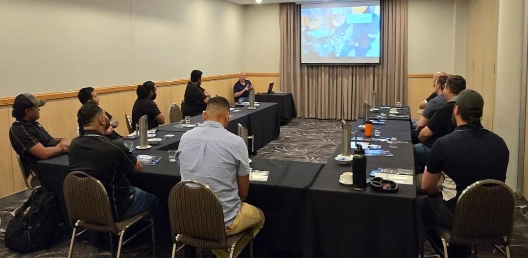
SDT Ultrasound Technical Events – Gladstone and Mackay
In collaboration with Machinery Consultation and Services Pty Ltd, the new distributor for SDT Ultrasound in Australia, the Queensland Branch was proud to collaborate on two exclusive events in Queensland this May. These were held in Gladstone on 14 May, and Mackay on 16 May.
Expertly led by Rob Dent (CMRP, CRL) from Canada, these sessions provided participants with hands-on experience, live demonstrations, and in-depth technical discussions on the use of ultrasound technology in condition monitoring.
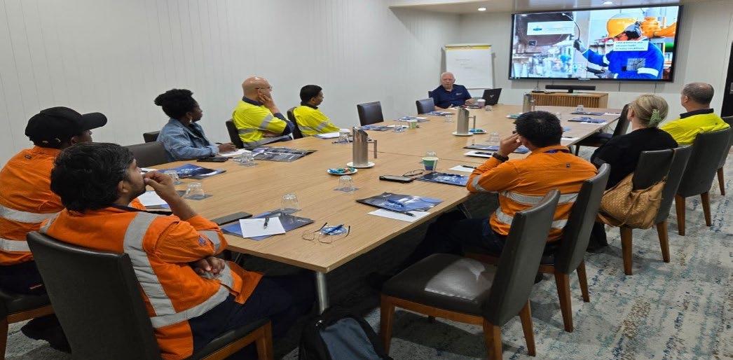
Rob’s global expertise and engaging delivery made both events invaluable for professionals looking to enhance their predictive maintenance capabilities.
The Queensland Branch would like to extend its sincere thanks to our own Salah Attia from MCS for his efforts in organising and sponsoring these valuable events.
Looking Ahead: AGM Dinner in Bundaberg
As we continue this exciting journey, we invite all members to save the date for our upcoming Queensland Branch AGM dinner on 26 July 26 in Bundaberg. This year’s AGM will be a little different, and more exciting! It promises to blend business with celebration, and we encourage members from all corners of Queensland to join us for what will be a memorable evening.
Stay engaged, stay curious, and stay tuned, more great events and learning opportunities are on the way.


Join us for a night of food, drinks and lively conversation
Friday 15 August 2025
Little Bang Brewing Company 25 Henry Street, Stepney

Western Australia Branch Update
While the past 60 days have been quieter compared to recent periods of technical evening activity, the Western Australia Branch remains actively engaged behind the scenes. We continue to seek out valuable opportunities and initiatives to deliver meaningful benefits to our members.
Following our May Council meeting, the Organising Committee has commenced preparations for the Western Australia Annual General Meeting. We encourage you to save the tentative date of Friday, 1 August 2025. Further details, including the venue and program, will be shared in due course.
In other news, after noticing a LinkedIn post by Edith Cowan University regarding the launch of WA’s first research and innovation lab with a focus on NDT projects, the WA Branch decided to reach out.
We contacted Executive Dean of Engineering, Professor Paulo De Souza and arranged a meeting on 13 May. WA Councillors, Mark Welland and Nathan Lenane, attended the Edith Cowan University Joondalup campus on behalf of the AINDT and were impressed to hear of the connection the university has with Germany’s largest and most influential applied research organisation, Fraunhofer.
Fraunhofer is one of three major nonuniversity research organisations and comprises of over 75 institutes. Seventy percent of Fraunhofer’s funding comes from contract research projects, making it highly responsive to market needs.
During the meeting, we were introduced to some of the engineering faculty (Dr Ferdinando Guzzomi, Senior Lecturer, Mechanical Engineering and Dr Faisal Awan, Technical Support Engineer), both with impressive engineering and research accolades. On the table for discussion included collaboration on projects, potential PhD opportunities with university students and ways AINDT can assist with raising the profile of NDT and inspection technology within the engineering degree pathway.
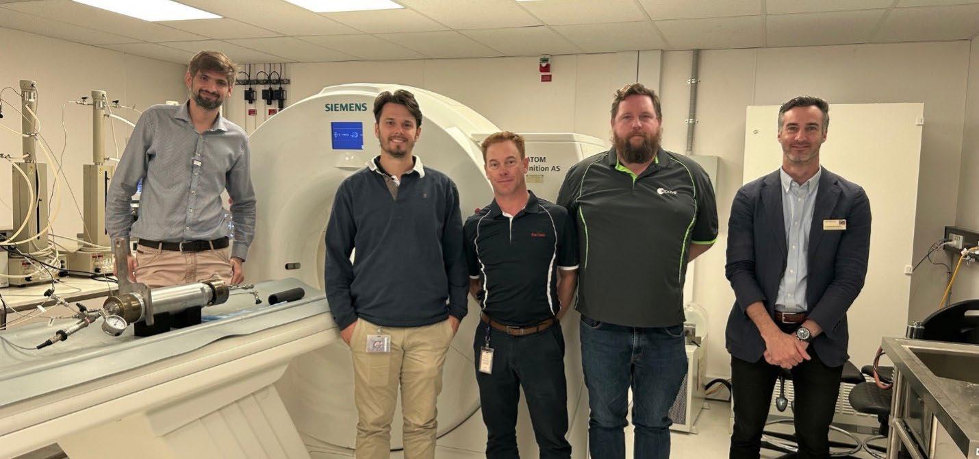
After a brief tour of the campus engineering department, we were treated with a visit to the Industrial Computed Tomography Bay. Dr Faisal Awan informed us that typical operating parameters for their CT scans are up to 140kV and 70mA.
ECU and Fraunhofer are presenting three free NDT webinars in the month of June and July. Details in the links below.
17 June from 3pm to 4pm AWST Wireless Sensor Systems For Safe Offshore Structures – CoMoBelt®
24 June from 3pm to 4pm AWST Mobile Ultrasonic Rail Testing System
1 July from 3pm to 4pm AWST From Fiber to Component – Current Testing and Monitoring Techniques for CFRP
A future technical evening might have a focus on what ECU are working on. WA AINDT members, keep your eye out for an invite.
Thank you to ECU, specifically Nicol-Marie Owen and Professor Paulo De Souza.
From L to R: Dr Faisal Awan, James Hill, Nathan Lenane, Mark Welland, and Dr Ferdinando Guzzomi.
Victoria and Tasmania Branch Update
The Victorian Branch continued its activity over the past two months, with a key focus on transparency, member engagement, and enhancing the value of technical and social events.
Discussions around certification and CB processes are ongoing, with growing concern about PCN transfers, multisector practical exams, and recertification requirements. Our council is committed to bringing clarity to this space, and Samad Asghari has been tasked with drafting documentation to support improved transparency and better communication around qualifications.
We’re also exploring ways to celebrate member contributions, including certificates of appreciation for outgoing councillors, and revisiting the J.H. Cole Award to better understand and promote its significance. In line with our ongoing recognition efforts, we’ve supported the nomination for the Meritorious Service Award.
On the membership front, Glen Haberl is liaising with the national office on membership renewals and database reports. Meanwhile, a new “What Members Want” survey - coupled with an incentive (Gold Class movie tickets) - is being developed by Darryl Pierce to better understand the needs of our community.
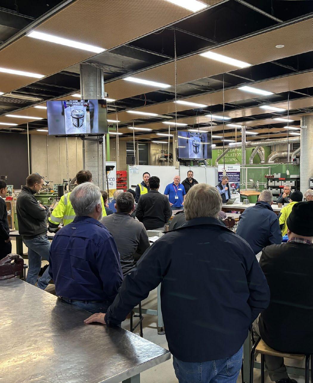
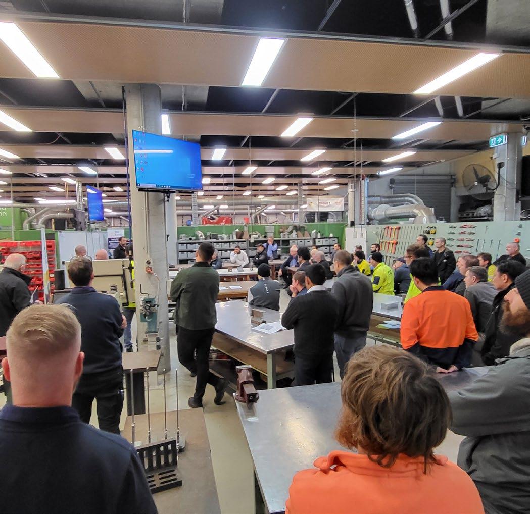
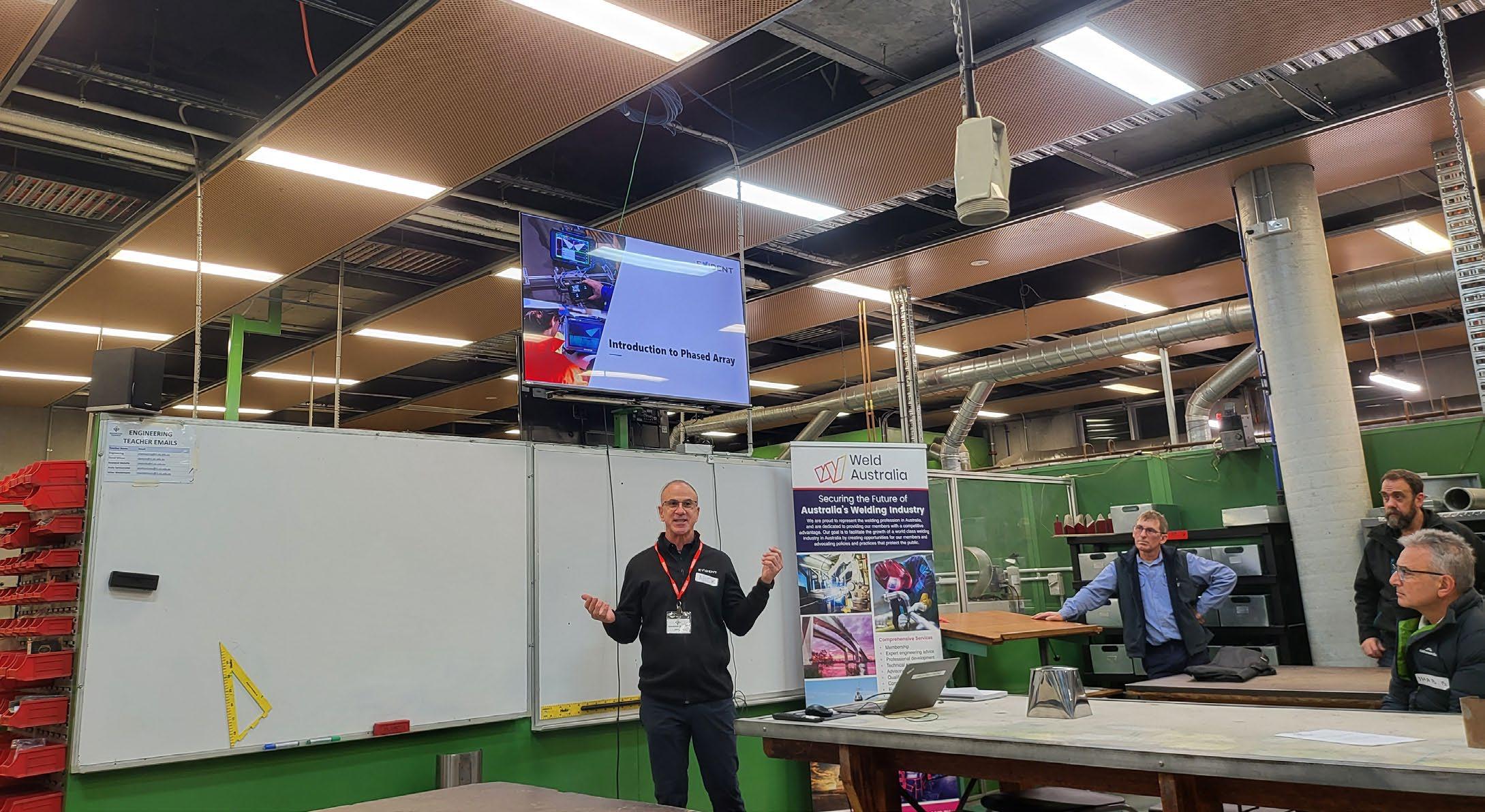
As always, we’ve been working hard to grow our event calendar. While technical night attendance has fluctuated, the recent collaboration with Weld Australia at Ringwood Training was a standout success.
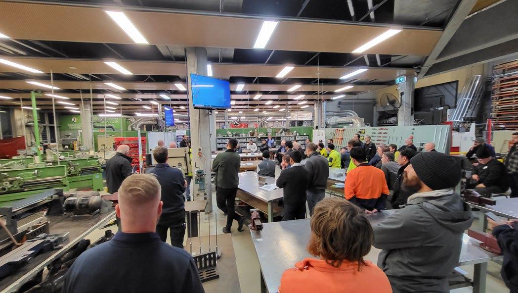
Laser Welding and Advanced Ultrasonics for Weld Testing
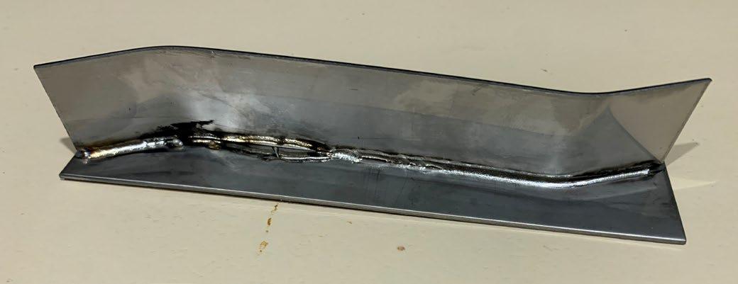
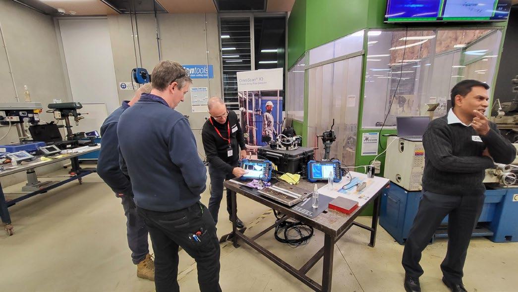
An excellent evening was had in conjunction with Weld Australia at the Ringwood Training facility at the end of May. Attendees were treated to a live demonstration of a joint being laser welded, followed immediately by phased array ultrasonic inspection - a powerful demonstration of how NDT works in tandem with advanced welding techniques.
Special thanks to the team from Evident Scientific, who showcased a phased array inspection of a 25mm multi-pass weld from one of the welding apprentices. The setup, displayed live on a large overhead monitor, drew considerable interest.
One favourite was the ‘heavy industry’ plasma cutterthe only one of its kind at any Australian training facility - slicing through 16mm carbon steel with precision in under 30 seconds. The noise, sparks, and molten spray
were impressive (from a safe distance), and the machine’s capability of cutting up to 80mm in a single pass was a standout talking point.
The highlight was the chance to try out manual laser welding, following an engaging talk and Q&A. Attendees were both fascinated and relieved to learn about the unit’s extensive safety systems - capable of damaging eyesight at 150 metres in milliseconds if misused. Equally impressive was how minimal the heat input was, with the welded component cool to the touch immediately after fusion.
The evening closed with pizza and networking, allowing professionals from across disciplines - NDT, welding, training, and engineering - to share stories and ideas. The event reinforced how beneficial cross-industry events can be, offering insight and inspiration beyond our usual scope.
What’s Ahead in 2025
The Victorian Branch has several exciting events planned in the coming months:
• ET/VT Technical Night in July
• PCTE Concrete Testing Night in October
• Thermography Night TBA
• AGM 2025 in August (dates and nominations to be announced)
• Christmas Party in Q4
• Mental Health Awareness Night an initiative in development
A huge thanks to everyone who continues to give their time and energy to the Victorian Branch. Whether you’re a councillor, volunteer, or member attendee, your involvement keeps our branch active, relevant, and futurefocused.
We encourage all members to share ideas for events or improvements and, most importantly, to turn up! These nights aren’t just about CPD point. They’re about community, growth, and good conversation. Let’s keep the momentum going.
Thermography in Action
Finding IR Window Transmission Values
BY ERIK THORUP, DIRECTOR IR TECHNOLOGY AUSTRALIA PTY LTD
CATEGORY
3 THERMOGRAPHER, ELECTRICAL/MECHANICAL (AINDT/BINDT)
“IR Windows” is probably a bit of a misnomer, since they do usually not transmit as much as we sometimes think. I have been involved with a site where an IR window was added in a wall to separate the flammable content inside from the non-intrinsically safe IR camera outside.
Apparently, nobody had mentioned that the “Window” only transmitted 50%, so the alarm value would be overshot in real life, before it would go off. However the cameras and IR surveillance programs usually have a setting you can change to obtain a more precise reading.
IR windows are now used in both High Voltage and Low Voltage installations, as well as in some mechanical plant, where direct line of sight access to the vital parts is otherwise impossible.
If you have the opportunity to perform an IR window transmission test before it is installed, the following “procedure” might assist you.
First: There are a Lot of Warnings
A precise transmission value cannot be found for an IR Window with a solid mesh.
Infrared radiation from an IR Window will have reflected radiation (sometimes from the temperature of the camera itself), radiation from the window material itself due to its own temperature, and finally transmitted radiation from the objects behind the window, which themselves can be reflected from some other surfaces behind the window. So it is not always easy to use any given or found values in the field.
A given transmission value may be temperature dependant, and may change over time for some materials, or when the window material gets dirty or has condensation on it.
Procedure yo Find Transmission Value
Let’s TRY to get some numbers for a real IR Window. I had at my disposal a H.VIR, High Vision Infrared. Range 0.3-13µm (SOREM).
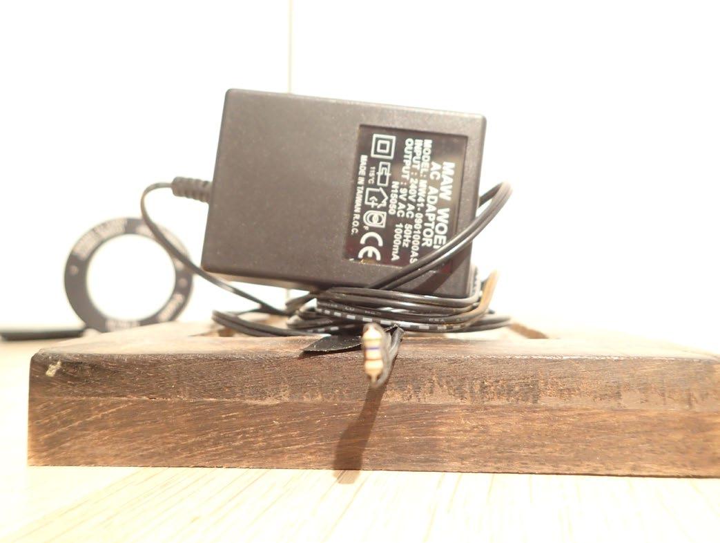
I also had a “mobile hot spot” made up of a discarded phone charger and a small resistor. See Fig.1.
The setup for the procedure in my somewhat tepid garage can be seen in Fig.2.
The camera is at a slight angle to the window so the reflection cannot be seen.
The following is necessary for the procedure to work well.
The IR Window must be situated in a room with fairly even temperature between the Window, and the walls around it. In this case the 16°C garage where the window had been stored for days, on a fairly evenly cold day in Melbourne, was found to work well.
See Fig.3 for a thermogram of the Window in situ. For my measurement in this case, I have used Emissivity of 1.00 and do therefore not have to worry about the Apparent Reflected Background Temperature.
It is recommended to FIRST check the Windows Reflection, since, if this is high, you may have to pay attention to this as well as the Transmission.
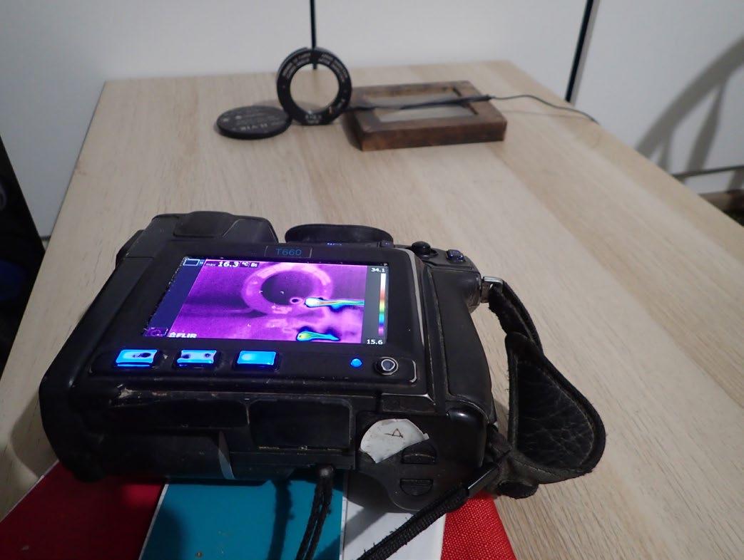
Fig.1 AC Adaptor 240V/9V, and a small resistor attached, make up the “mobile hot spot”.
Fig.2 The IR Window is placed on a table and the hot spot is positioned where necessary. The IR camera placed in front at a slight angle.
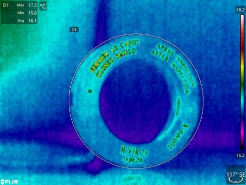
A Thermal Image is recorded of the IR window in position. Average temperature was found to be 16°C. The text can be seen as it is reflecting the heat from the operator and camera. The hot spot was positioned in front of the window to see if there was any significant reflection. The Image was showing a faint reflection in the window.
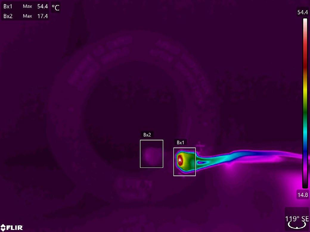
The Hot Spot can be seen at 54°C and a slight reflection can be seen in the 16°C window showing 17.4°C. Already now we may consider that the reflection is not going to have any influence, but if we want to have a value for the Reflection we can adjust the camera or program settings like this:
B. Transmissivity
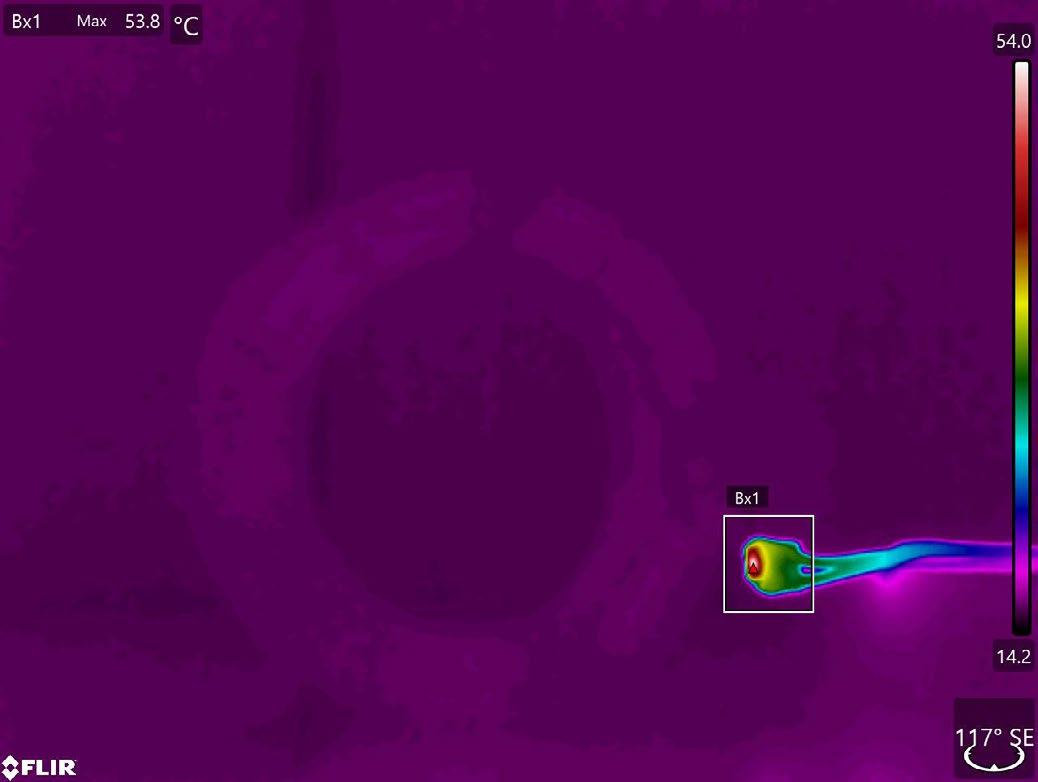
To find the transmissivity we first measure the temperature of the hot spot directly without the window, and get 53.8°C. We then move the hot spot behind the
This means that with this fairly rudimentary set up we have determined the Windows Transmissivity to 78%, its reflection to 3% and therefore the window itself will provide 19% of its own radiation due to its own temperature. It must be emphasised that not all windows have this transmittance, and the values mentioned here should not be used without confirmation of the real actual values.
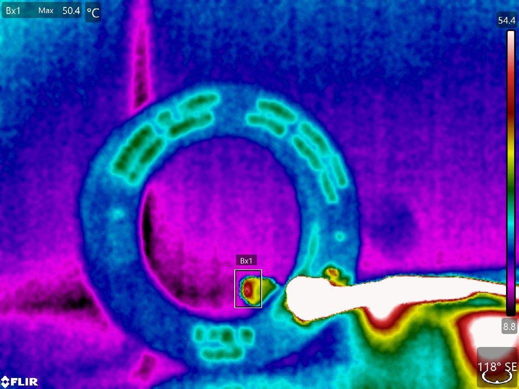
Set the Reflected Background Temperature to 16°C, and dial the Emissivity down till you get the original value of 54.4°C. We can only get as close as 50.4°C for a value of 0.04. The reflection is approximately 4%. (0.03 gives 60°C, and 0.05 gives 44°C)
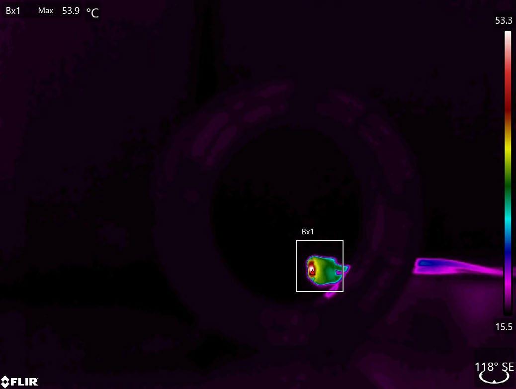
window and measure it at 46.5°C, and with the Reflected Background
Temperature set to 16°C, we dial the Emissivity down till we reach 53.9°C which happens at 0.78
Conclusion
It is possible to determine the transmission and reflection of an IR window using your camera and having a hot or cold spot which is much warmer or colder than the window, if you have access to a radiometric IR camera, a hot (cold) moveable test specimen, and access to both sides of the window. The procedure here is based on the window being situated in an environment where the room (and reflecting walls) are the same temperature as the window itself.
A. Reflection
In Memory of Gregg Voak : A Colleague, Mentor and True Gentleman of NDT
On 8 May 2025, the global NDT community lost a respected expert, a dear friend and colleague.
BY JIM TIBANI (SALES MANAGER, WAYGATE TECHNOLOGIES, BAKER HUGHES)
Gregg Voak’s passing has left a noticeable silence in a world where his voice, laughter, and steady guidance once played a key role, both technically and personally. For those of us privileged to know and work with him, Gregg’s memory is one that will long be carried with warmth and gratitude.
Gregg’s NDT journey spanned over three decades, where he established himself as a master of digital radiography, a field in which he demonstrated technical depth and visionary leadership during his time with GE Inspection Technologies and beyond.
His deep domain expertise positioned him as a natural leader. He led the Global Digital Conversion Sales Team from Antwerp, Belgium between 2008 and 2013, a role that reflected his knowledge, his ability to unite teams, drive change, and build strong relationships across borders.
I personally came to know Gregg when I moved to Australia. I was new to the country, trying to find my feet, and Gregg never hesitated to offer encouragement, advice, and genuine friendship. He made time for people, and he made them feel seen. That support didn't stop when our roles changed or when he moved on. It stayed, as did his respect for people, regardless of their background or title.
Gregg also played a meaningful role within AINDT, particularly during his time as GEIT’s Corporate Member. He collaborated closely with the Institute, supported events, and sponsored winners award across the country. His presence was always appreciated, not just for what he knew, but for how he shared it. He had that rare ability to explain complex technologies in a way that made others feel more capable, not less.
One of Gregg’s colleagues once said, “He has a heart bigger than Australia.” That sentiment has echoed in the many messages shared since his passing. From USA, through Europe and Asia to Brisbane, from GE to Baker Hughes, colleagues have remembered Gregg as someone who combined professionalism with kindness, and leadership with laughter.
At his core, Gregg was someone who believed in people. He believed in mentoring the next generation, in sharing knowledge freely, and in helping others grow, often in ways they didn’t even realise until much later. He brought warmth and integrity into every conversation,

and he made the industry, and the world, just a little better by being in it.
Beyond the workbench and training rooms, Gregg had another passion that showcased his precision and focus: RC soaring. He was a legend in Australia’s radiocontrolled gliding community, representing the country at multiple international championships. Whether it was in the sky or in a sales meeting, Gregg brought the same attention to detail, patience, and quiet determination that defined his approach to everything he loved.
His sudden passing has left many of us shocked and heartbroken. But as I reflect on his life, I am reminded of how much Gregg gave in knowledge and in spirit. He lived with purpose, worked with passion, and treated others with respect and care. And for that, he will be remembered, not just as a colleague, but as a friend, mentor, and one of the good ones.
Rest in peace, Gregg. Your legacy lives on in the people and community you helped shape. You will never be forgotten.
In Memoriam – Dr Peter Trampus
It is with deep sorrow and profound respect that the International Committee for Non-Destructive Testing (ICNDT) mourns the passing of Dr Peter Trampus, a distinguished leader in the field of non-destructive testing and a cherished member of our international community.

Dr Trampus, from Hungary, served with unwavering dedication as the President of the European Federation for NDT (EFNDT) and was a long-standing contributor to ICNDT’s mission. His exceptional vision, tireless efforts in promoting excellence in NDT, and commitment to international collaboration have left a lasting legacy across Europe and beyond.
A physicist by training and a professional of the highest calibre, Peter was admired for his intellect, integrity, and inclusive leadership. His efforts were instrumental in fostering cooperation between NDT societies, enhancing the quality of personnel certification, and advancing research and innovation in our field.
On a personal note, I, as the current Chair of ICNDT, am deeply indebted to Dr Trampus for the unwavering support and wise counsel he offered me throughout my term. His guidance, encouragement, and quiet strength have been a source of confidence and clarity in steering
the global NDT community through times of both progress and challenge.
Beyond his technical contributions, Peter was a mentor, colleague, and friend to many of us. His calm demeanour, thoughtful insights, and genuine kindness made him not only a respected leader but also a beloved figure within our community.
As Chairman of ICNDT, I extend our heartfelt condolences to his family, friends, and colleagues at the Hungarian NDT Society and the broader EFNDT and Academia International network. His absence will be deeply felt, but his legacy will continue to inspire generations of NDT professionals around the world.
May he rest in peace.
Dr Sajeesh Kumar Babu Chairman, ICNDT
AINDT Member Profile
Q&A with Dean Pozzan
With a background that spans from cabinet making to nondestructive testing (NDT), Dean Pozzan’s career journey is anything but ordinary. As part of his family’s business, Bundaberg Metallurgical and Welding Services, Dean has developed deep expertise across a range of NDT methods and welding services.
Guided by his father’s mentorship and a strong passion for learning, Dean continues to build a career grounded in technical excellence and collaboration. Here, he shares insights into his path into the industry, professional achievements, and personal aspirations.
Where do you work? Describe your job.
I work for my father’s company, Bundaberg Metallurgical and Welding Services in Bundaberg. It is a family run business with my father Ron as the managing director, myself looking after the NDT side of the company, and my younger brother Warrick whom also is a NDT technician.
There are two aspects to our company. NDT methods (including Visual Testing (VT), Penetrant Testing (PT), Magnetic Particle Testing (MT), Eddy Current Testing (ET), Ultrasonic Testing (UT), Phased Array Ultrasonic Testing (PAUT) and Magnetic Wire Rope Testing) and welding related services (such as PQRs, WQs, weld supervision, mechanical testing and failure analysis).
Can you share your journey into the NDT industry? What motivated you to take on a career in NDT?
I sort of fell into the NDT world I suppose, like a lot of people I have spoken with. I am a cabinet maker by trade and in 2014 I was in Tasmania on a Big W fit out, when I came down with Ross River Fever, which floored me back home on the couch for about a month.
Of course, then I started going around with Dad to various clients giving him a hand. Once I got back on my feet, I thought this is much less taxing on the body than strapping on a nail bag, and the rest is history.
Who or what has influenced you most professionally?
I would have to say my father has been my biggest influence and mentor. He is such a wealth of knowledge, having a Bachelor of Science in Metallurgy and nearly 60 years of experience, not only professionally but also in all other areas. Our Level 3s Dave Kirk and Ian Hogarth have also been a wealth of knowledge for me.
What has been the most interesting project you’ve worked on and why?
One of the most interesting projects I’ve been involved with recently is a dragline shutdown, where we carried out boom chord replacements. We used Phased Array Ultrasonic Testing (PAUT) as the primary inspection method and replaced the centre chord (CD). Working closely with management and welders throughout the process, we were able to deliver a successful outcome.
What advice would you give to someone just starting their career in the NDT industry?
Something my father has told me from the start: Knowledge is no weight to carry, so keep reading, gaining knowledge and apply it out in the field.
What has been your greatest professional achievement?
My greatest professional achievement would be gaining above 90% in UT 2 and PAUT courses.
How has being a member of AINDT benefited you professionally or personally?
Being a member of the AINDT has kept me up to date with what’s happening locally and internationally. It is also a great platform now to keep up to date with my log book for the various methods through my online portal. What are the top three things on your bucket list?
Well I would have to say that being the best husband to my wife and father to my family is at the top. Second would be to become debit free. Third would be to still be surfing and wing foiling at the age of 70.
Rapid Fire Questions
• Favourite Food: Reef and beef
• Favourite Song: There’s too many, though have been back into Neil Younge lately. Prairie Wind
• Favourite Sport: Surfing and wing foiling
• If you could be famous, what would it be for?
I’m fascinated with exploring the world by ocean, so it would have to be circumnavigating the world by boat.
• If you could meet anyone—alive or dead—who would it be? Jesus
• What is your pet peeve? Coming across jobs that are not done correctly from the beginning.
• What is your top tip for NDT excellence? There is a method for everything. Do it right from the beginning and the end results will speak for itself.
Dean Pozzan’s

Bundaberg Metallurgical and Welding Services: Delivering Precision and Reliability for Over Two Decades
Since opening its doors in 1997, Bundaberg Metallurgical and Welding Services (BMWS) has built a strong reputation as a trusted provider of specialist metallurgical and welding expertise across central Queensland. Family-owned and operated, the company combines deep technical knowledge with a hands-on, customer-focused approach to deliver quality outcomes for clients in engineering, construction, mining and manufacturing.
With capabilities spanning fabrication and welding inspection, welding supervision, welder and procedure qualifications, nondestructive testing (NDT), and laboratorybased materials analysis, BMWS offers a truly comprehensive service.
Whether supporting large-scale industrial projects or assisting local businesses, the team is known for its responsiveness, accuracy and commitment to best practice.
BMWS’ highly skilled personnel are equipped to conduct a full range of NDT services, including visual inspection, dye penetrant, magnetic particle, ultrasonic, eddy current and wire rope testing. Their metallurgical lab services—such as bend and fracture testing, metallography, defect and failure analysis, and inspection and test planning—are tailored to meet the unique requirements of each project.
Backed by modern technology, years of industry experience, and a genuine passion for quality, BMWS partners closely with clients to provide reliable insights that support safety, compliance and longterm performance.
Their local knowledge, combined with national-standard expertise, makes them a go-to resource for businesses seeking dependable, technically sound advice and service.
Whether you’re qualifying welders, validating materials, or needing expert failure analysis, BMWS is the team you want in your corner. Their mission is clear: to elevate standards, support local industry, and deliver exceptional results—every time.
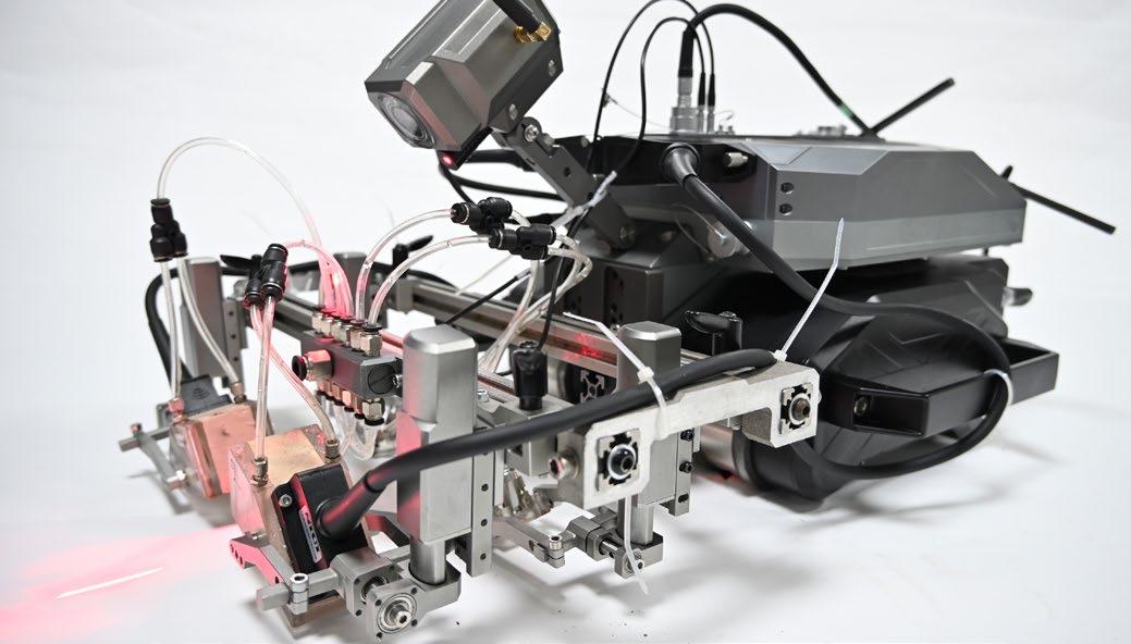
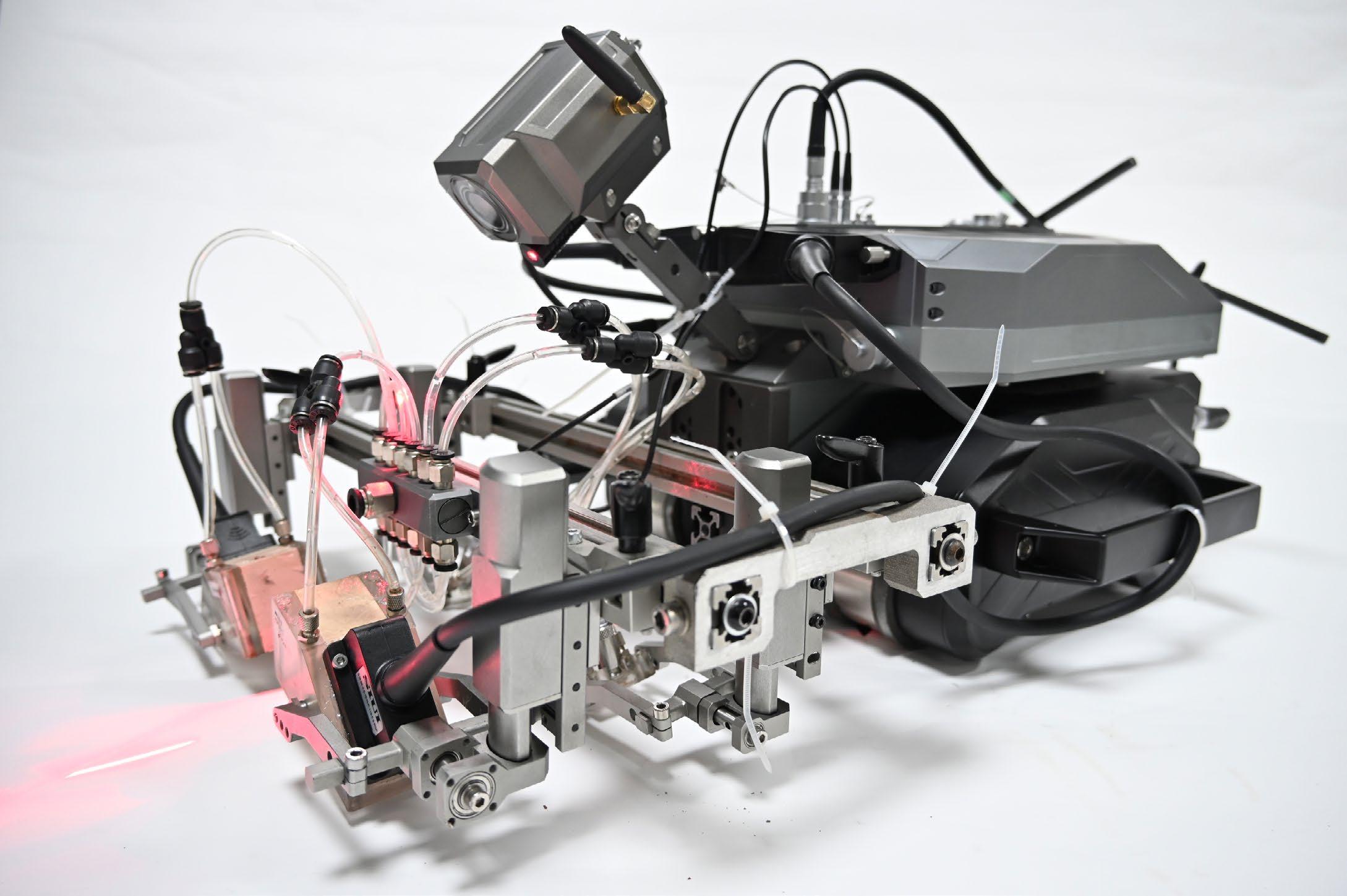
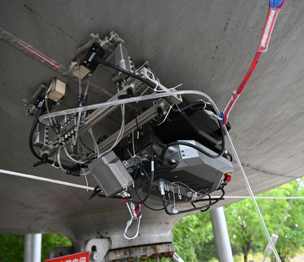
A New Climb: How the ALPHA 1006 is Redefining Weld Inspection at Height
Wind towers. Spherical tanks. Turbine piping. These structures share more than just scale and complexity—they each present a formidable challenge to non-destructive testing (NDT) professionals tasked with inspecting critical welds in extreme conditions.
BY JOHN DUENZL, SIMPLIFI NII
For years, inspection teams have relied on rope access and scaffolding to visually or ultrasonically assess these welds, often under harsh environmental pressures and at significant personal risk. It’s a method that, while brave and occasionally poetic, has long been overdue for disruption.
That disruption now has a name: ALPHA 1006.
Inspection Innovation That Stays Grounded—
Literally
The ALPHA 1006 is a self-contained, steerable, wallclimbing inspection system developed by SIUI. It integrates phased array ultrasonic testing (PAUT) and time-of-flight diffraction (TOFD) directly into the scanning unit, eliminating the need for bulky external instruments or tangled cables.
Its most immediate impact? Ground-based operation. Technicians no longer need to scale structures. Instead, they remotely control the scanner’s movement and inspection parameters from a safe vantage point—greatly reducing fatigue, physical risk, and overhead costs.
From Harsh Conditions to High Precision
Engineered for real-world complexity, the ALPHA 1006 has demonstrated success across various scenarios:
• Wind turbine towers at sub-zero temperatures, inspecting compound V-groove welds on 7-meter diameter structures
• Spherical tanks up to 20 meters wide, with wall thicknesses exceeding 38 mm
• Hydroelectric turbine pipes in muddy, slick environments with fluctuating surface curvature
Despite these variables, the scanner maintains reliable coupling and positional accuracy thanks to adaptive magnetic wheels, dual-motor drive, and real-time encoder feedback.
An All-in-One Software Ecosystem
The ALPHA 1006 is paired with a fully integrated software suite that supports every stage of inspection:
• Workpiece simulation
• Probe setup and calibration
• Real-time PAUT/TOFD acquisition
• Live wireless data transmission
• Automated reporting and data review
All components—from coupling checks to laser-assisted weld alignment—are engineered for efficiency and easeof-use in the field.
Modular, Expandable, and Future-Ready
Designed with modularity in mind, the ALPHA 1006 supports expansion up to eight probes, and can be configured with a motorised dual-axis raster scanner for corrosion mapping.
Whether deployed on vertical towers or the curvature of a storage tank, the system scales to suit each task— without the need to rebuild or rewire between jobs.
Beyond Robotics: Rethinking the Inspection Mindset
While robotic NDT is not new, what makes the ALPHA 1006 significant is its practicality. It doesn’t just replace a technician—it enables them. It reduces the effort required for reliable, repeatable inspection and positions the inspector as a data-driven analyst rather than a rope-suspended daredevil.
This shift matters. Especially as infrastructure ages and renewable energy assets demand more frequent,
precise inspection, systems like the ALPHA 1006 offer a compelling path forward—without compromising safety or data quality.
Conclusion: The Climb is Over
The ALPHA 1006 represents a maturation of the NDT field’s relationship with automation—not a novelty, but a working tool for working inspectors. It’s a solution born from real industry needs, delivering real performance, and opening the door to smarter, safer inspections across sectors.
For once, innovation doesn’t require a leap. It just needs a better climb.
Key Benefits
• Ground-based operation – safer for inspectors
• Magnetic wall-climbing scanner – adapts to curves
• No trailing cables – powered by lithium batteries
• Expandable – supports 8 probes and raster arm for corrosion mapping
• Real-time wireless monitoring – up to 160m From weld inspection to corrosion mapping, the ALPHA 1006 brings a new level of safety and efficiency to high-altitude and hard-to-reach NDT applications.
What ALPHA 1006 Offers
• Magnetic wheels that adapt to curved surfaces with industrial-grade grip
• Dual motors for flexible movement in all directions
• Lithium battery power – no bulky cables
• Real-time monitoring via a wireless camera feed
• Modular setup – expand to 8 probes or add a raster arm for corrosion mapping
• IP66-rated build – rugged and waterproof
About the Author
John Duenzl is the Director of Simplicity for NonIntrusive Inspections (Simplifi NII), an Australian company specializing in advanced non-destructive testing solutions.
With over two decades of experience in the NDT field, John is renowned for his innovative approach to inspection technologies and his commitment to enhancing safety and efficiency in industrial operations. He actively contributes to industry discussions and developments, sharing insights through various professional platforms.
AXT and VisiConsult Partner to Deliver Cutting-Edge X-ray Solutions to Australian Industry
Driving digital transformation in NDT with AI, automation, and advanced imaging for mining, defence and additive manufacturing
AXT, a leader in Australia’s X-ray technology landscape, has announced a strategic expansion of its portfolio through a new partnership with German-based X-ray systems manufacturer VisiConsult. This collaboration marks a significant step forward in delivering highperformance, intelligent Non-Destructive Testing (NDT) solutions tailored to Australia’s unique industrial and research environment.
VisiConsult brings over 25 years of experience in designing and manufacturing advanced X-ray systems under its VCxray brand. Already relied on across aerospace, defence, energy, and electronics sectors worldwide, their technology integrates automation, robotics, and AI-powered software—such as Automated Defect Recognition (ADR)—to boost efficiency, accuracy, and readiness for the digital future.
Through this partnership, AXT and VisiConsult aim to deliver a complete, end-to-end NDT solution portfolio for the Australian market. This ranges from standard catalogue systems to fully customised platforms for sectors like defence and mining, and is rounded out by a powerful software ecosystem that supports the full journey from conventional to fully digital inspection processes.
At the core of this transformation is VisiConsult’s commitment to enabling the shift from traditional RT film inspection to modern digital workflows. This evolution is powered by high-resolution Digital Detector Array (DDA) systems, supported by VC.acquire—VisiConsult’s robust digital acquisition platform—and enhanced further by
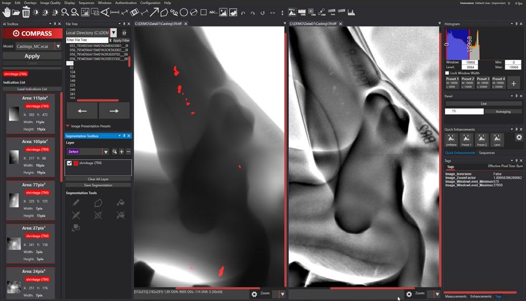
the AI-powered solution Compass, which autonomously detects flaws in digital images, significantly accelerating inspection processes and improving reliability.
The partnership also brings the Diondo CT product line to Australian labs and research institutes, providing high-resolution computed tomography (CT) systems ideally suited for additive manufacturing, quality assurance, and advanced materials research.
“We are thrilled to be working with VisiConsult,”
said Richard Trett, Managing Director at AXT. “Their technologies perfectly complement our offerings and will allow us to break into new markets, particularly in defence and advanced manufacturing. We’re already collaborating on major projects and see strong demand across the country.”
“Our goal is to support Australian customers at every stage of their digital NDT journey—from initial system acquisition to full AI-enhanced inspection workflows,” said Jason Robbins, Division Lead Commercial at VisiConsult. “AXT’s established presence in NDT, research, and additive manufacturing makes them the ideal partner to drive this transformation.”
With this collaboration, AXT and VisiConsult are positioned to become key enablers of innovation in the Australian NDT landscape—empowering industries to modernise, scale, and meet the highest quality standards.
For more information about VisiConsult solutions, including VCxray X-ray inspection systems and software innovations as well as Diondo CT product lines, visit www.axt.com.au
Figure 1. VC.Acquire software with COMPASS module works on a variety of materials and manufacturing techniques. This comparison shows a casting with cavities, which the AI-supported module reliably detects –on the left in the image. These are otherwise only visible with the help of special image filters – as can be seen on the right – and are difficult to detect. Image copyright VisiConsult X-ray Systems & Solutions GmbH.
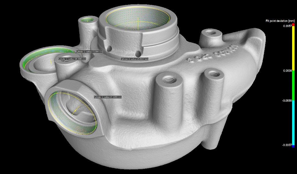
Figure 2. 3D reconstruction of an automotive casting, generated using computed tomography. Image copyright VisiConsult X-ray Systems and Solutions GmbH.

RENEW YOUR MEMBERSHIP

RENEW FOR REWARDS: STAY A STEP AHEAD WITH 2025-2026 AINDT MEMBERSHIP
Whether you're looking to enhance your knowledge, expand your network, or influence industry standards, AINDT is your gateway to success. Connect with top professionals and thought leaders in an environment that celebrates innovation and progress. Just some of the member benefits are outlined below.
Regular editions of the AINDT Journal (6 per year)
Substantial discounts on certification fees and expenses
Access to our online portal and resources
Eligibility for exam and industry service awards
A host of networking opportunities, including branch events, workshops, seminars, and our conference
Exclusive Corporate Member benefits like free and discounted advertising rates, and technical advice
MEMBERSHIPS ARE NOW DUE
Advanced Phased Array Inspection for Early Detection of HTHA
High-temperature hydrogen attack (HTHA) is one of the most critical failures that assets in the oil and gas or chemical industries may experience, and can lead to environmental contamination, explosions, injury, or even loss of life. For this reason, industries are constantly looking for better methods to detect HTHA at its early stage, when corrective action can still be initiated.
BY FLORIN TURCU AND SABRI BABA, EVIDENT SCIENTIFIC
This study reveals how the latest dedicated phased array (PA) scanners and probes from Evident now enable early detection of HTHA defects—when it is still possible to prevent critical damage to the assets. We describe the strategy used to inspect a weld sample suspected of being affected by HTHA internal damage and present the results of the analysis. We also cover important points, including inspection configuration and data analysis, giving a thorough overview of the process of HTHA detection.
An Introduction to HTHA
High-temperature hydrogen attack (HTHA) is a damage mechanism that affects aging assets, including vessels, hydrocrackers, and heat exchangers in the petrochemical industry. It occurs when hydrogen molecules contained in a liquid or gas hydrocarbon penetrate steel components and combine with carbon atoms inside the steel lattice to form methane.
The HTHA process has two important consequences that affect material properties. First, by reducing the carbon content of the steel, HTHA reduces the metal’s hardness; second, build-up of gas pockets at grain boundaries or at other interfaces inside the material can affect the structural integrity of the steel.
When combined, these processes can substantially increase the risk of asset failure, with potentially catastrophic consequences.
The risk of HTHA affecting a steel component depends on factors such as age, composition, length of exposure to hydrogen, temperature, and partial pressure. From a structural point of view, methane build-up within the metal causes small (micro) cracks that are impossible to detect non-destructively, but over time these cracks may form clusters or connected cracking that may be “visible” with some non-destructive testing (NDT) methods. One powerful technique for detecting these small
cracks is phased array ultrasonic testing (PAUT). While other techniques such as eddy current enable only subsurface inspection, PAUT can provide detailed maps of indications in components up to 100 mm in thickness, using detectors placed on only one side of the material.
PAUT uses an array of elements to detect ultrasound signals deflected from interfaces such as cracks, voids, and impurities, meaning that with the correct equipment configuration, PAUT can detect HTHA microcracks with a high sensitivity and resolution.
Current Standards in HTHA Detection
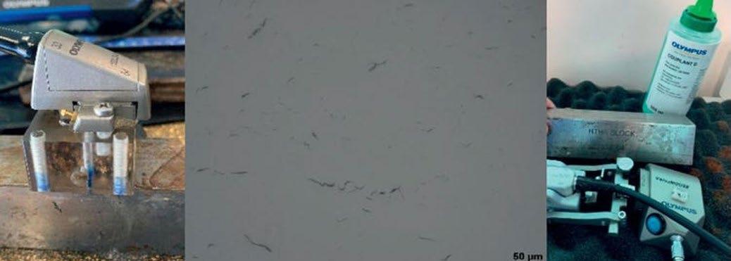
There are a number of key regulations outlined by the American Petroleum Institute (API) designed to standardize the process of HTHA detection. For example, API Recommended Practice 941 [1] describes the use of one or a combination of technologies for the detection of HTHA, including TOFD (time-of-flight diffraction), PAUT, and TFM (total focusing method). The API code sets staging guidelines for HTHA damage as follows (Figure 1):
1.Incubation stage—undetectable by NDT
2. Optical stage—damage can be detected optically (micrograph)
3. Stage of rapid mechanical property deterioration
4. Cracking stage
To prevent damage to affected materials, HTHA must be detected as early as possible. However, early stage HTHA is usually characterized by fissures or microcracks that can be difficult to differentiate from material imperfections such as inclusions or even grain
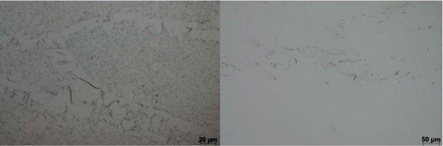
Figure 1.HTHA in the optical stage (left) and connected fissures form cracks (right).
boundaries. Although cracks present in advanced-stage HTHA can be detected with ultrasound testing, it is often too late to deal with the problem effectively at this stage, as there is already an increased likelihood of equipment failure.
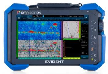
The Latest Developments in HTHA Detection Solutions
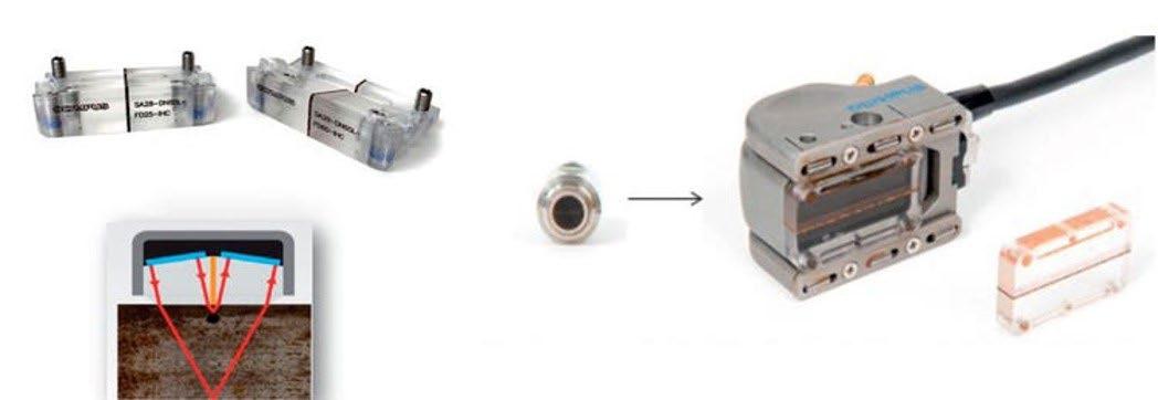
Adding to its existing range of scanners and TOFD probes for the OmniScan™ X4 flaw detector, Evident recently launched a series of dedicated probes designed for the detection of early stage HTHA. These solutions include highly sensitive linear PAUT probes for lownoise, high-gain TFM inspection, a series of highfrequency TRL (transmitting-receiving-longitudinal) angle-beam probes (Figure 2), wedges for inspection under the weld cap, and Dual Linear Array™ (DLA) probes for completing inspection of the heat-affected zone (HAZ) or body of a vessel (Figure 3).
Detecting HTHA within a component requires high sensitivity and high penetration power, making dual probes a natural choice for accurate inspection. Typical dual probes (based on two single elements or arrays) have the capability for geometric focusing, in which two acoustic elements define the bases of a triangle, whose tip is the point of geometrical focus.
The angle at which the two elements are oriented toward the sound propagation path (the so-called ‘roof angle’) gives the depth of geometrical focusing for such a transducer (Figure 4). By combining geometrical focus with the focusing power achieved using high-frequency sound waves (10 MHz), dual array transducers offer both passive and active focusing to concentrate the sound intensity at a given area of interest.
Another advantage of dual probes is the removal of potential noise-generating internal wedge reflections. This is thanks to the design of the receiver, which is completely isolated from the transmitter by an acoustic barrier. This means that only echoes arriving from the inspected part are registered, allowing the wedge to be built shorter, minimizing the sound path through Rexolite and saving energy for propagation through the steel.
Evident’s 10 MHz Dual Linear Array probes (10DL32-A28 and 10DL64-Rex1) are provided with wedges that enable geometrical focusing at depths of 15 mm, 25 mm, and 60 mm, and also provide an electronic focusing capability for up to around 80 mm. This means that 10 MHz DLA probes can be used up to a depth of 95 mm in steel components.
Methods of Sensitivity Calibration and Weld Inspection
As with most amplitude-based measurement and detection techniques, PAUT requires calibration of equipment sensitivity prior to the inspection. This is usually achieved by scanning metal blocks that are manufactured to contain induced cracking or known side-drilled holes (SDHs) with sizes closely matching that found in HTHA.
In this study, 0.2 mm diameter SDHs in a cluster were used for the initial sensitivity calibration. The acquisition gain was increased in steps of 18 dB and the sensitivity was then validated against acquisitions on a block with artificially induced cracking prior to weld sample inspection. The reference blocks and probes used are shown in Figure 5.
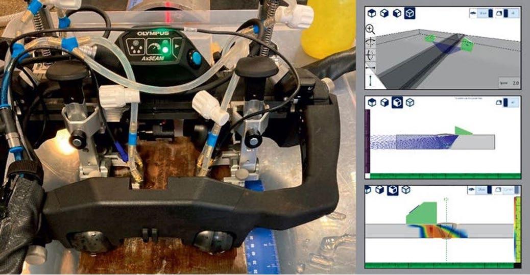
After calibration, a sample of material suspected of being affected by HTHA was chosen for inspection. The sample used was a 150 mm × 150 mm block from a larger weld belonging to a heat exchanger (Figure 6).
The inspection strategy involved several steps:
1. Screening the weld volume with high-frequency TOFD (time-of-flight diffraction)
2. Scanning with a dual PA angle-beam probe:
1. The weld volume was scanned with sectorial scans from 40 to 70 degrees with probes positioned on each side, at 15 mm and 30 mm, from the weld centerline (4 scans).
2. The HAZ was scanned with sectorial scans from −15 to 15 degrees on each side, at 15 and 30 mm, from the weld centerline (4 scans).
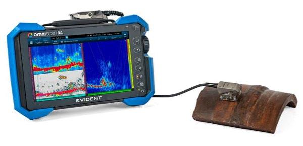
Figure 2. A28 angle-beam T/R probe for weld inspection and the OmniScan X4 flaw detector.
Figure 4. Concept of a DLA probe (top left) and its geometrical focusing (bottom left) and replaceable focused SA28 wedges (right).
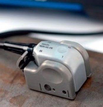
Figure 3. 10 MHz DLA probe for 0-degree inspection of the HAZ and body (left) and A31 high-sensitivity linear probe for TFM (right).
3. The entire suspected area excluding the weld was then scanned using a 0-degree dual-linear probe
4. TFM was subsequently used to scan the weld volume for confirmation
5. Finally, WeldSight™ software was used to merge the data and perform an automated analysis
In the first phase, the weld sample was screened with an AxSEAM ™ scanner (Figure 6) mounted with 15 MHz TOFD probes, followed by scanning with a dual PA angle beam to cover the weld and a linear 0-degree beam to cover the HAZ. As well as providing capabilities for both circumferential and longitudinal scanning, the AxSEAM scanner also enabled parameters such as acquisition speed and coupling efficiency to be continuously monitored through the on-board ScanDeck™ module. In the second phase, a DLA probe (Figure 3 left and Figure 4 top left) was used to complete scanning of the HAZ and the zones adjacent to the weld with 0-degree beams. After the TFM acquisition was performed using dedicated linear probes, the data were subsequently merged in WeldSight software, which provides detailed automated analysis for rapid flaw detection.
Weld Inspection Results
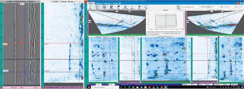
TOFD Scanning Results
The results from the TOFD screening revealed several connected indications extending from 65 mm (from the inspection datum) up to the end of the inspection area. The same array of indications was revealed by the 51-degree B-scan acquired with the right skew angle. The indications seem to be positioned underneath the weld centerline, at a depth of around 14 mm. TOFD and PA data confirming the same indication is shown in
Figure 7, and an overview of the scan is shown on the right-hand side of the figure.
The data acquired in step two of the inspection strategy were first imported into WeldSight software and merged. The result is a top, side, and an end view of the part, displaying several of the detected indications (Figure 8).
The volumetric top view (top-right view in Figure 8) shows a particular concentration of flaws in the weld volume in the second half of the scan, as well as in the right-hand side of the scan. Looking at the side and end views, the flaws predominantly cover the last 5 mm range of the thickness above the back wall. In addition, the side view shows more indications, which are visible from 40 mm toward the scan end, confirming the TOFD data. A series of indications previously detected with TOFD are also visible between 70 mm and 120 mm on the scan axis.
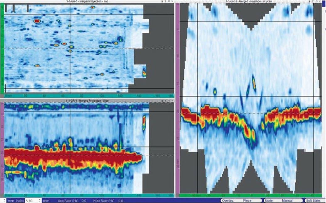
Figure 8. 10DL64-A28 DLA probe—sectorial (40 to 70 deg.) scan, skew −30, −15, +15, and +30; sectorial (−15 to +15 deg) scan, skew −30, −15, +15, and +30 mm. All angle beam data merged: top view (top left), end view (right), and side view (bottom left). Flaws are concentrated in the weld area and the right-hand side of the HAZ.
Dual Linear Array Probe Results
The inspection performed in step 3 of the strategy used the 10 MHz DLA probe depicted in Figure 3 and wedges with a roof angle that enable a focus point at 15 mm (geometric focusing). Together with the electronic focusing set at 15 mm, a high-intensity ultrasonic beam was directed perpendicular to the back wall and used to scan the entire suspected area, with the exception of the weld cap and volume.
Figure 5. SDH reference block (left) and induced HTHA block for validation (centre and right).
Figure 7. Side-by-side comparison of TOFD and dual PA B-scan at 51 degrees (left) and the connected cracks were confirmed by dual phased array (right).
Figure 6. AxSEAM scanner used for TOFD, PAUT, and TFM scanning and the respective scan plans (top to bottom on right).
The irregularity of the weld cap prevents efficient coupling between the PA probe and the sample. The data generated after scanning with the DLA probe was subsequently merged and analysed in WeldSight software. As shown in Figure 9, a large number of indications are visible at depths ranging from 11 mm to the back wall of the sample. The software’s cluster analysis tool detected 100 indications over the entire scanned area.
TFM Results
The last step involved confirming the presence of tiny indications using the TFM method. For this analysis, scanning was performed using the linear high-frequency probe as shown on the right in Figure 3, with the probe covering both the left and right side of the welded sample. After this analysis, several of the indications previously identified were confirmed by the TFM data. An example is given in Figure 10, where the T-T (transverse-transverse) propagation mode was used. T-T is a pulse-echo wave set where both legs of its path are transverse waves.
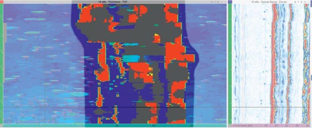
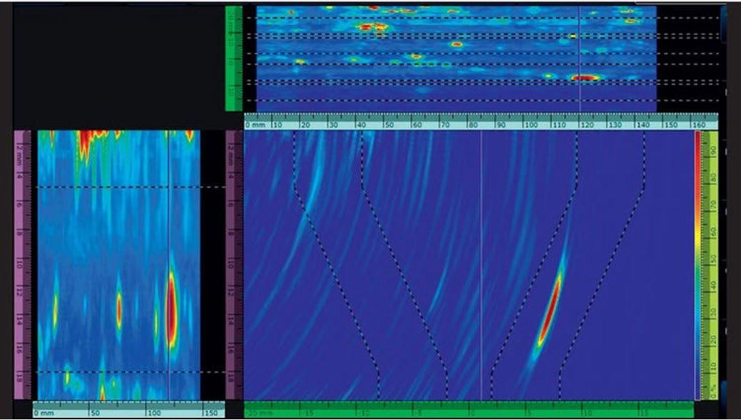
Conclusions
The HTHA inspection conducted was based on a reference block with SDHs of 0.2 mm in diameter. With the acquisition amplitude of the SDH set at 80%, HTHA inspection was performed with an acquisition gain increased by 18 dB. The combination of high gain, small wavelength (0.6 mm for 10 MHz L-waves), and steep focusing in the passive aperture (roof angle) with both physical and aperture separation of transmitter and receiver (T/R probes) enabled a very high sensitivity of detection with minimal wedge and material noise. The inspection process permitted the complete inspection of the weld body and its HAZ, as summarised below:
Weld Volume
The weld volume was scanned with angle beams, TFM, and TOFD. Several indications were detected—some with a connected crack pattern—which was confirmed by all three techniques. Other indications looked more like random cracks or inclusions, while some isolated indications presented higher reflectivity.
HAZ and Adjacent Area
More indications were detected at 0 degrees in the HAZ compared with angle-beam sectorial scanning. These were randomly displaced with higher concentration on the left-hand side of the weld.
The results of this study show PAUT to be a powerful method for detecting early stage HTHA—associated inclusions were detected using three different methods (TOFD, geometric focusing, and TFM) with Evident PAUT technology.
While the nature of the indications cannot be entirely classified as being HTHA damage or inclusions, it is clear that tiny discontinuities can be detected using Evident phased array probes with separated transmitters and receivers, either in angle-beam or zero-degree scanning.
References
1. Steels for Hydrogen Service at Elevated Temperatures and Pressures in Petroleum Refineries and Petrochemical Plants. API Recommended Practice 941, Eighth Edition, February 2016
2. www.twi-global.com/technical-knowledge/faqs/ what-is-high-temperature-hydrogen-attackhtha-hot-hydrogen-attack
3. www.olympus-ims.com
Figure 9.Inspection with DLA PA probe (10Dl64-Rex1) in the HAZ. Cluster analysis—approx. 100 flaws detected.
Figure 10. TFM data acquired on left skew along the sample, looking at the weld volume.
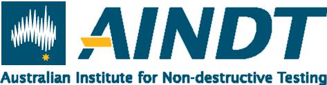
SHAPE THE

Join the vibrant team of volunteers at your local state branch and turn your passion for progress into action. Volunteer with us and connect with a community of professionals dedicated to making a difference in our industry. W H Y V O L U N T E E R ?
Network with industry leaders and peers
Develop professional skills and gain unique experiences Influence the direction of our industry and contribute to meaningful change aindt.com.au


Advancing Condition Assessment of Post-Tensioned Ducts Using Ultrasonic and Impact Echo Data
Post-tensioned (PT) girders are widely used in bridge construction, where the grout system serves two purposes: transferring the load between tendons and concrete and protecting the tendons against corrosion.
AREZOO IMANI1A, MARISOL TSUI CHANG1B, DALE SANFORD1C, SHANE BOONE1D, ANNETTE ADAMS2E
1BDI, LOUISVILLE, CO, USA
2VIRGINIA DEPARTMENT OF TRANSPORTATION, FREDERICKSBURG, VA, USA
AAREZOOI@BDITEST.COM; +1 720-670-1281
BMARISOLT@BDITEST.COM CDALES@BDITEST.COM
DSHANEB@BDITEST.COM
EANNETTE.ADAMS@VDOT.VIRGINIA.GOV
However, environmental exposure and poor-quality construction practices can compromise the grout system quality, resulting in voids, soft grout, or corrosion. This study presents a comprehensive multi-modal nondestructive evaluation (NDE) methodology to assess the integrity of the grout system using ultrasonic testing, impact echo, GPR, and HRI. Instead of relying solely on the ultrasound magnitude, the phase and real part were incorporated as well to improve condition assessment. Additionally, impact echo signatures were established and compared with individual spectra to assess the grout condition. This approach demonstrates the effectiveness of integrating multiple technologies and analysis techniques to detect potential deficiencies in PT systems and support maintenance practices.
Keywords: pre-stressed, post-tensioned, ultrasonic testing, phase analysis, impact echo, bridge preservation
Background
The average age of bridges in the United States is 46 years, with nearly 44% over the age of 50. According to the 2023 National Bridge Inventory (NBI) database, out of the 621,000 bridges in the country, approximately 69% are reinforced concrete, while 27% are prestressed concrete bridges [1]. Although reinforced concrete bridges have been constructed since the early 1900s, the majority of the pre-stressed bridges were built after the mid-20th century [2]. Many of these structures incorporate post-tensioned (PT) elements due to their cost- effectiveness and performance advantages.
Condition assessment of PT girders presents unique challenges compared to conventionally reinforced structures. Visual inspection of bonded PT systems is not feasible without destructive probing and opening access windows into the ducts. Unlike conventionally reinforced elements, signs of deterioration in PT elements typically
do not become visible unless significant damage has occurred. Additionally, drilling and exploratory probing may not be permitted by the asset owner, and any openings provide only limited information confined to the area in the vicinity of the access window.
Researchers and practitioners have used nondestructive evaluation techniques with varying degrees of success to characterize the grout condition [3, 4]. In this study, complementary use of several NDE technologies was explored. Ultrasonic testing, impact echo (IE), ground penetrating radar (GPR), and high-resolution imaging (HRI) were used to characterize the grout condition within the bonded post-tensioned ducts of a signature bridge in Virginia. The complementary use of these advanced techniques significantly improved the accuracy and reliability of the PT system condition assessment.
1.1 Bridge Information
The Lord Delaware Bridge, located in West Point, Virginia, carries US 33 over the Mattaponi River. Constructed in 2006, this multi-span concrete bridge features prestressed, precast bulb- tee girder approach spans, and two four-span-long continuous spliced PT precast bulb-tee girder center spans. Each of the eight PT spans consists of seven girders.
During a routine biennial inspection conducted in 2015, only nine years after the bridge opening, inspectors reported concrete spalling around post-tensioned ducts. Findings included exposed stirrups, perforated ducts, and surface corrosion on the tendons, raising concerns about the internal conditions of the grouted ducts and the integrity of the steel strands. Previous investigations on the PT systems in this bridge and its adjacent sister bridge (the Eltham Bridge, carrying US-33 over the Pamunkey River) revealed issues such as soft grout, loose grout, voids, standing water, and corrosion of PT strands within the ducts [5].
These discoveries prompted the Virginia Department of Transportation (VDOT) to initiate an in-depth investigation into the bridge’s PT system to determine the extent of this degradation and inform maintenance and preservation plans.
The bridge spans 1,081 m (3,545 ft) in length and has a total width of 21.5 m (70.5 ft), carrying two traffic lanes in each direction (eastbound and westbound), along with a wide shoulder.
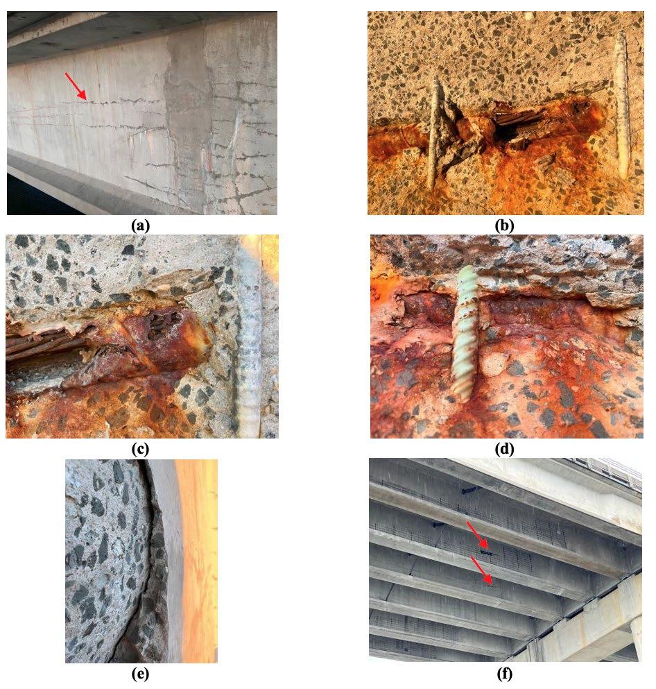
2. Field Observations
Some of the initial field observations from December 2023 are presented in Figure 1. Surface- opening cracks were observed on the exterior face of the fascia girder 7. The cracks on the web wall appeared to coalesce around the ducts. Near the diaphragms, the cracks were more extensive and propagated in various directions. While the exposed stirrups on the east end of the south fascia girder were black reinforcement bars, the exposed stirrups on the west end of the same girder in
the same span were epoxy-coated. Using different types of steel reinforcement creates a potential imbalance within the member, which can drive corrosion [6]. Some delamination and spalling were observed over the ducts. Elevated moisture levels within the surface-opening cracks were evident.
3. NDE Methodology
GPR, ultrasonic testing, impact echo, and high-resolution imaging were used for this investigation. GPR was used
Figure 1. Representative initial observations: (a) existing cracks along the ducts as well as horizontal and 45° cracks that were sealed near the diaphragm/closure pour, (b) corroded duct and exposed strands, (c) black bar and corroded duct, (d) epoxy-coated bar and corroded duct, (e) delamination and spalling, (f) moisture seeping out of surface-opening cracks over the ducts on a rainy day.
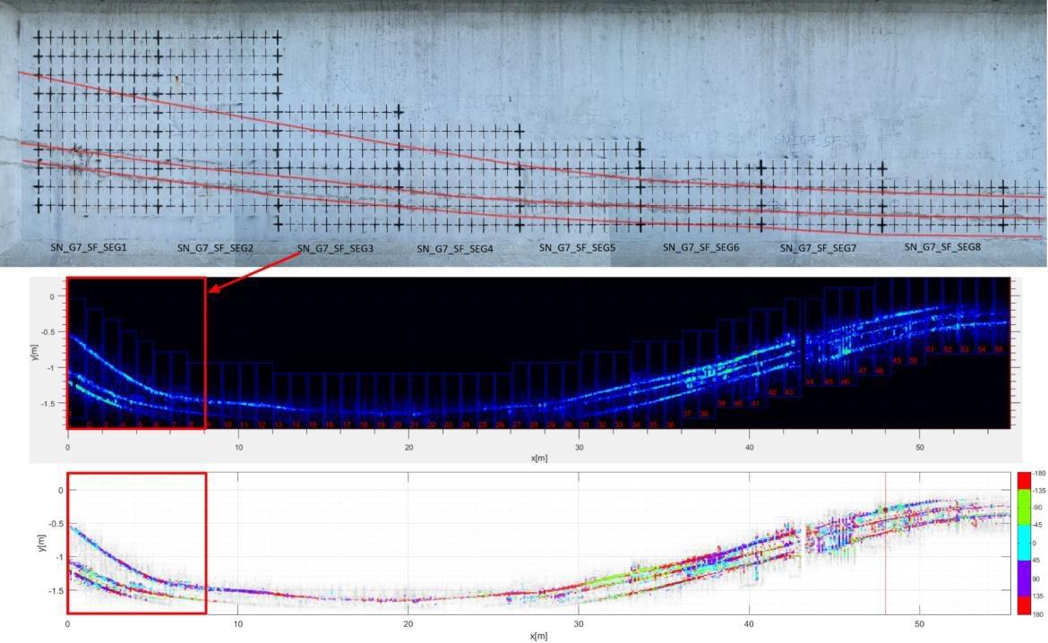
to determine the location of the ducts and the stirrups. The stirrup location was determined to avoid interfering with the impact echo response and to help with ultrasound data interpretation. Ultrasound and impact echo were used to locate potential voids or soft grout. HRI was used to document the existing conditions and the duct locations, as determined by GPR and marked on the web walls. The high-resolution images provided additional insight when interpreting the ultrasound and impact echo findings.
A handheld stepped-frequency GPR manufactured by Proceq was used to locate the ducts and the stirrups. A MIRA 3D Pro system manufactured by ACS International was used for ultrasonic testing. The ultrasound data analysis was performed using InterSAFT. Impact echo testing was performed using an Olson Engineering CTG2 system. The ultrasound and impact echo testing are further discussed in the following sections.
3.1 Ultrasound Testing
Ultrasound measurements were collected on 150 mm × 100 mm (6 in × 4 in) grids across hundreds of 1-m (3.2-ft) long segments with varying heights. This approach ensured efficient data collection while avoiding measurements in web areas that were irrelevant to assessing the grout conditions. Over 4,800 linear meters (15,750 linear feet) of PT ducts were examined. Figure 2 illustrates representative ultrasound test segments, including the grid layout and the draping ducts. The ultrasound testing was conducted with the
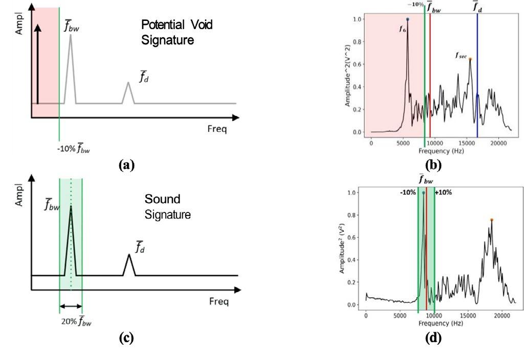
3. (a) Spectrum signature for potential void conditions, (b) a representative spectrum for a location with potential void, (c) spectrum signature for sound void conditions, (d) a representative spectrum for a location with sound condition.
long axis of the equipment oriented vertically. Each data set was individually analyzed, and the segments were subsequently stitched together to produce the results for the entire length of each girder in each span. The magnitude, phase, and real part of the ultrasound data were considered to interpret the grout conditions. Numerical simulations complemented the field measurements, providing additional insight to help inform the interpretation of the ultrasound data.
For ultrasonic data, phase calibration is essential to identify the type of reflector within the test element. The phase is calibrated by adding a phase offset to all calculated phase values, where the offset is defined as
Figure 2. Representative ultrasound test grid and segments.
Figure
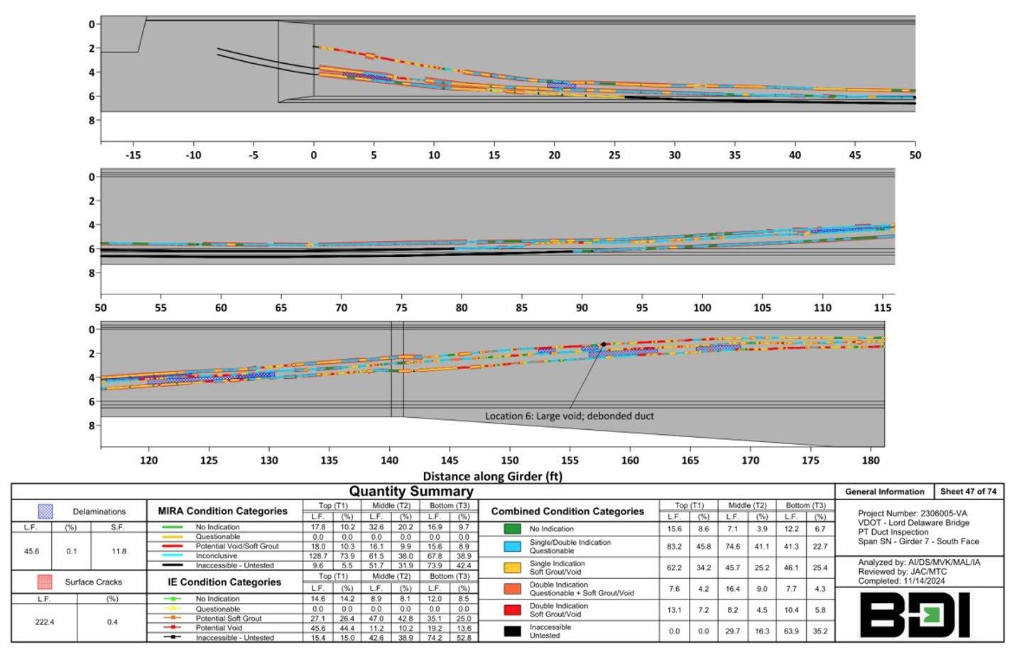
the average phase at a known interface; in this case, the backwall interface (i.e., the concrete-air interface on the opposite face of the web wall). Once calibrated, reflections that have a similar calibrated phase but follow the shape of the ducts
can be interpreted as air-filled voids within the ducts. On the other hand, reflections with the same calibrated phase as the backwall appearing outside the duct area are likely indicative of discontinuities within the surrounding concrete. Ideally, concrete girders of the same size and material should have the same calibrated phase for backwall reflections. However, inherent imperfections in the concrete can change these values, making it challenging to identify anomalies through automated algorithms. Thus, the interpretation must be performed individually for each segment. In contrast, impact echo allows for more straightforward and automated identification by matching the dominant frequency with a list of pre-determined known signatures, enabling a faster classification of the grout condition, although the probability of false alarms is higher for impact echo compared to ultrasound testing.
3.3 Impact Echo Testing
Impact echo testing was conducted on the same 1-m (3.2-ft) segments described for the ultrasound testing. Though impact echo measurements were taken on the same grid lines as the ultrasonic measurements, data was only taken at every other vertical grid line, leading to measurements spaced horizontally 200 mm (8 in)
apart. Measurements were primarily taken directly over the ducts to assess the condition of the grout, while measurements were also taken above the ducts to assess the condition of the concrete itself and to calibrate the velocity. The dominant frequency from each measurement was compared to the expected backwall and duct frequencies (9.2 kHz and 16.8 kHz, respectively) established on sound concrete at the start of the project. This comparison was the basis for assigning a condition category to each location. Four condition categories were established: sound, questionable, potential soft grout, and potential void, all determined from the dominant frequency at each location compared to the duct and backwall expected frequencies.
As examples, the “potential void” and “sound” signatures are shown in Figure 3 (a) and (c), compared with IE spectra in (b) and (d). For potential void, the dominant frequency peak is less than the calibrated backwall expected frequency minus 10%, as shown in red. The sound signature has a dominant frequency within 20% of the calibrated backwall expected frequency.
3.4 Joint Ultrasound-Impact Echo Interpretation
After both ultrasonic and impact echo testing were completed and interpreted individually, their results were used to create joint condition categories for each testing location. The joint categories range from No Indication, where both testing methods predicted sound grout conditions, to Double Indication, where both testing
Figure 4. A sample condition map for the wall shown in Figure 2.
methods predicted either soft grout or void within the duct.
Data from each wall was combined into an overall condition map, with the ducts color-coded to match the joint signatures at each location. Delaminated concrete, as located via ultrasonic testing, and surface cracks along the ducts, as located via HRI, were also marked on the maps, though surface cracks away from the ducts were left unmarked. The physical length and percent of the total length for each of the joint signatures were recorded to allow for comparison between maps. An example map is shown in Figure 4. Overall statistics, combining the results from each of the 74 walls tested, were also calculated, providing a general look at the condition of the ducts across the entire bridge. These statistics can be found in Table 1.
Table 1. Summary of statistics for the joint results
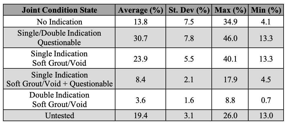
4. Physical Verification
Using the results of NDE testing, 71 locations were selected for physical verification. The ducts were opened at 68 of these locations, while the remaining three were used to confirm the existence of delaminated concrete identified using ultrasound testing. Once the ducts were opened, if voids were present, a borescope was used to investigate the extent of the voids and search for other defects within the duct.
Of the 68 duct openings, 28 (38%) saw solid grout with no voids, while 25 (37%) had voids and 33 (38%) had soft grout. Though it could not be detected via ultrasound or impact echo, corrosion on the tendons and duct was also noted, occurring in 27 (38%) of the duct opening locations. Additionally, water was found at 11 (15%) locations.
Due to the fact that both ultrasound and impact echo testing are mainly effective in regions of concrete without extensive surface cracking, statistics on the reliability of both methods were calculated, with cracked areas excluded.
A total of 28 of the 55 non-cracked locations were expected to have voids based on this NDE investigation, out of which 23 locations were observed to have voids after opening. For soft grout, 32 locations were expected, out of which 28 locations were found.
Equations 1 and 2 were used to calculate the probability of detection (POD) and probability of false alarm (PFA)
for voids and soft grout for both NDE methods [7]. The statistics used in the calculation are in Table 2.
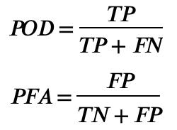
In these equations, TP is the number of true positive results, FP is the number of false positives, TN is the number of true negatives, and FN is the number of false negatives [7].
The POD for voids and soft grout was 90% for impact echo and 88% for ultrasonic testing, while the PFA was 86% for impact echo and 61% for ultrasonic testing.
Table 2. Positive and negative counts for both NDE methods
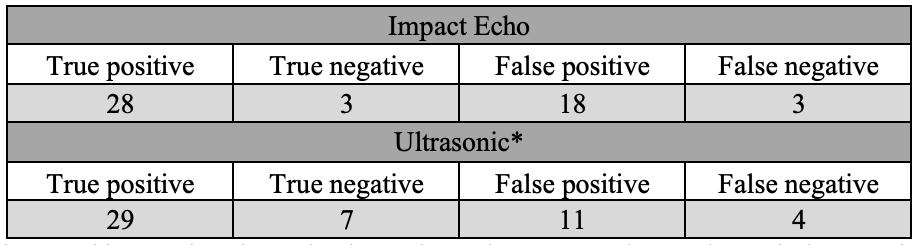
*Note that ultrasound has one less data point due to the equipment returning an “inconclusive” result in one location.
4.1 Representative Duct Opening
Figure 5 and Figure 6 depict representative locations where the ultrasonic and IE data indicated potential voids. The impact echo results, in Figure 5 (b) and Figure 6 (b), indicate potential voids, due to the dominant frequency peak being more than 10% below the backwall expected frequency, similar to the IE void signature illustrated in Figure 3 (b). In the bottom plot in Figure 5 (a), the backwall can be clearly seen as a large reflector with the phase in cyan color. A similar cyan reflector can be seen at the level of the duct (circled), suggesting a potential concrete-air interface (void within the duct).
Figure 6 (b) is less straightforward due to a discontinuity (likely a delamination) causing scattering of waves slightly below the middle and bottom ducts. At this location, the backwall is visible, but its phase is shifted. However, the presence of the void could still be inferred from the phase value, which was later confirmed from the duct opening (Figure 6 (c)).
4.2 Critical Findings
The representative opening seen in Figure 6 (Opening #6) featured one of the critical findings. Alongside moisture, debonding, and a corroded duct, this location had voids extending at least 2.4 m (8 ft) in either direction, the full length of the borescope cable. along the girder from the opening.
The most significant finding, however, occurred at Opening #44. The galvanized duct itself at this opening had multiple holes due to severe corrosion, and a tendon was loose enough to be moved via hand tools. At least
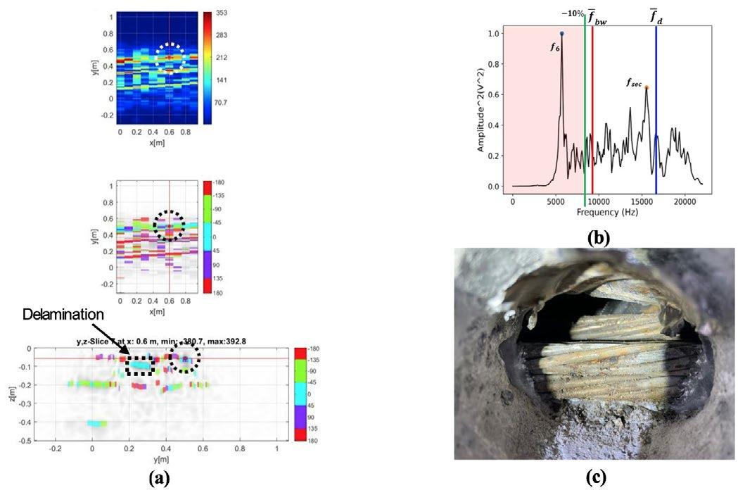
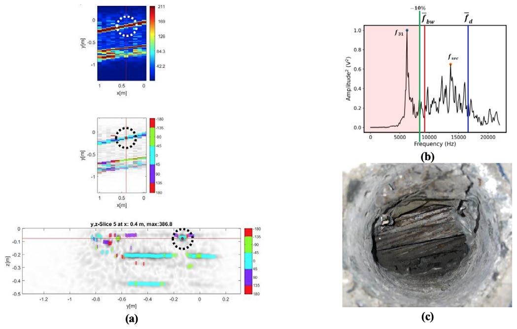
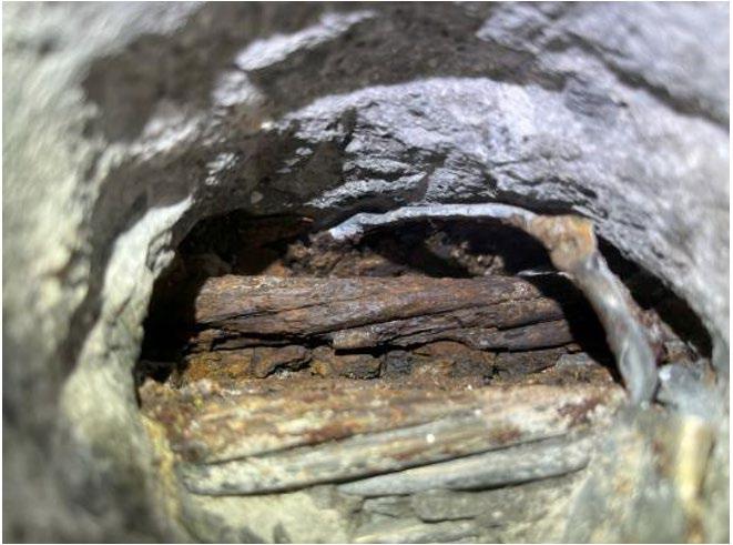
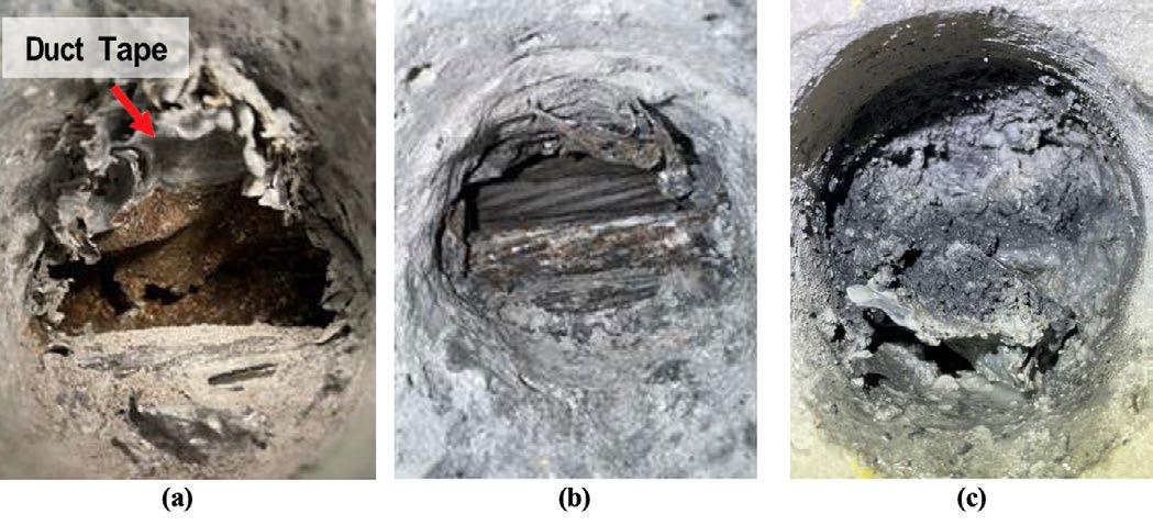
four wires on one of the strands were completely broken (Figure 7). Based on this critical finding, a stop work order was issued, and all personnel and NDE equipment were removed from the bridge. Subsequently, a bounded load rating was performed to determine whether the work could continue. The initial load rating findings showed that the PT spans could maintain a reasonable level of live load-carrying capacity despite some loss of prestressing strands. These findings were used as the basis for continuing with the NDE investigation and allowing traffic on the bridge without having to post it. During this evaluation, it was found that the results were likely conservative based on typical American Association of State Highway and Transportation Officials (AASHTO) assumptions for the controlling exterior girders. In turn, the owner requested that live-load testing be performed to evaluate the global structural behavior and quantify load distribution. The preliminary results showed no signs of distress along the instrumented spans, with the girders behaving in a stiff and expected manner and with a high level of load distribution.
These results, along with the NDE findings, will be subsequently used to provide an updated load rating for these middle-span PT units.
Another key critical finding occurred at Opening #38, where duct tape was found on the duct’s surface before
opening. The duct itself was brittle, and there was very little grout, with extensive voids in either direction from the opening. The main significance of this opening pertains to a 2015 paper by Sprinkel and Balakumaran. The authors report an anecdote from the grouting contractor stating that, during construction, to rectify a misalignment of the ducts, they were “winched with great force”, which resulted in the strands cutting the ends of the ducts. Subsequently, the cut ducts were wrapped with smaller cut pieces of duct, and the connection was sealed and secured using duct tape [5]. The findings here confirm the use of duct tape during construction. A photo of this opening is in Figure 8 (a).
Various other openings yielded conditions that were categorized as critical findings, including corrosion on the duct or tendons, soft wet grout, extensive voids, and liquid water. Examples of these are found in Figure 8 (b) and (c).
Conclusions
The use of multiple NDE methods allowed for the locating and quantifying of voids and soft grout within the post-tensioning system. Exploratory probing via the duct openings allowed for the assessment of the strand condition. The addition of physical sampling and material testing provided insight into the condition of both the metal duct and the grout from a chemical perspective. Following physical verification, it was found
Figure 7. The broken wires discovered at Opening #44.
Figure 8. (a) The brittle duct and the duct tape at Opening #38, (b) the corroded wire and void at Opening #12, and (c) the soft, wet grout at Opening #50.
Figure 5. (a) Ultrasonic testing results, (b) IE results, and (c) photo of the void in the duct at Opening #31.
Figure 6. (a) Ultrasonic testing results (with delamination marked), (b) IE results, and (c) photo of the void in the duct at Opening #6.

that the NDE methods had a combined probability of detection of ~90%. Through NDE, the interior condition of the bridge girders was determined across the entire length rather than just at select drilling locations, as would be the case in randomly selected drilling locations. Future preservation activities, such as draining water from ducts or repairing corroded strands, can be planned based on the NDE findings to inform specific locations for targeting rather than simply choosing the high points of the ducts. NDE proved effective at determining the conditions within the ducts: though the majority of voids were found at the high points, as expected, 30% of all observed voids were located on the bottom half of the girder and were only located via NDE.
Acknowledgments
The authors would like to acknowledge Dr. Klaus Mayer for his support and guidance on phase analysis.
References
[1] USDOT Federal Highway Administration, [Online]. Available: www.fhwa.dot.gov/bridge/nbi/ascii2023. cfm. [Accessed 25 7 2023].
[2] J. Holt, U. Garcia, S. Waters, C. Monopolis, A. Zhu, O. Bayrak, L. Powell, K. Halbe, P. Kumar and B. Chavel, "Concrete Bridge Shear Load Rating Synthesis Report," Federal Highway Administration , 2018.
[3] P. Paulík, T. Makita, L. Bathen, B. Godart, C. Hendy, J. Hunter, M. Kalný, G. Nordbotten, F. R. Stucchi, T. S. Theryo and E. Vonk, "fib Bulletin 110: Management of post-tensioned bridges," Fédération internationale du béton (fib), 2023.
[4] S. Hurlebaus, M. B. D. Hueste, M. M. Karthik and T. Terzioglu, "Inspection Guidelines for Bridge PostTensioning and Stay Cable Systems Using NDE Methods," Transportation Research Board, 2017.
[5] M. M. Sprinkel and S. S. G. Balakumaran, "Problems with Continuous Spliced Posttensioned–Prestressed Concrete Bulb-Tee Girder Center Spans at West Point, Virginia," Transportation Research Record, no. 2642, p. 46–54, 2017.
[6] U. Angst, B. Elsener, C. K. Larsen and Ø. Vennesland, "Critical chloride content in reinforced concreteA review," Cement and Concrete Research, vol. 39, no. 12, pp. 1122-1138, December 2009.
[7] F. Fücsök, C. Müller and M. Scharmach, "Measuring of the Reliability of NDE," Journal of Nondestructive Testing, Vols. 2007-04, pp. 173-180, 2007.
[8] K. Mayer, K.-J. Langenberg, M. Krause, M. Christiane, B. Milmann and C. Kohl, "Characterization of Ultrasonic and Radar Reflector Types in Concrete by Phase Evaluation of the Signal and the Reconstructed Image," Journal of Nondestructive Evaluation, vol. 27, pp. 35-45, 2008.
[9] K. Langengerg, R. Marklein and K. Mayer, "8th European Conference on NDT (ECNDT)," Barcelona, Spain, 2002.
[10] ASTM International, "Standard Specification for Portland Cement," C150, West Conshohocken, PA, 2007.
[11] "ACI 222R-19: Guide to Protection of Reinforcing Steel in Concrete Against Corrosion," Farmington Hills, MI.
NDT World Event Calendar
CONAENDI 2025: The 40th NDT and Inspection Conference and Exhibition
13 to 15 August | Sao Paulo, Brazil
The theme of the 40th edition of Conaendi is Knowledge, Technology and Innovation Shaping the Future of Inspection. With over 1,2000 participants and 40 exhibitors, the event will feature three intense days of technical content, with presentations on advanced research, technological innovations and an exhibition of companies focused on NDT, inspection, structural integrity, robotics and safety. The event offers an excellent opportunity to exchange experiences, interact with experts and discuss the latest trends and advances in the sector.
For further information, visit: conaendi.org.br
ASNT 2025: The Annual Conference
6 to 9 October | Florida, United States 'Access Granted' is more than just a theme—it's your key to the future of NDT. Join industry leaders as we explore innovations, share insights, and open doors to the latest advancements in NDT. This must-attend event provides unparalleled networking, hands-on technology showcases, and an immersive experience designed to expand your knowledge and elevate your career. Hosted by the American Society for Non-destructive Testing, ASNT 2025 will be held at Disney's Coronado Springs Resort, with over 100 technical sessions, 210 exhibitors and 2,200 attendees.
For further information, visit: asnt.eventsair.com/asnt-2025
55th NDE for Safety 2025
11 to 13 November | Litomysl, Czech Republic
The conference will cover all aspects of non-destructive testing (NDT) and evaluation (NDE) of materials and structures across a broad range of technical fields. Hosted by the Czech Society for NDT, the event provides a unique opportunity to bring together researchers, practitioners, and experts involved in the development, application, and standardisation of NDT/NDE methods. Manufacturers and service providers are also invited to showcase their latest products, technologies, and innovations.
For further information, visit: www.cndt.cz/en/conference
2025 AINDT Summit
18 to 20 November | Newcastle, Australia
The 2025 AINDT Summit will bring together industry leaders, innovators, and NDT professionals for three days of knowledge sharing, networking, and professional development in Newcastle from 18 to 20 November 2025. With the theme The Power of Inspection, the Summit will explore how inspection services deliver crucial insights about critical assets across industries. This timely theme also addresses Australia's evolving energy landscape and the expanding role of inspection services in supporting our future energy infrastructure.
For further information, visit: aindt.com.au
The 17th Asia Pacific Conference for Non-Destructive Testing (APCNDT)
11 to 14 May 2026 | Hawaii, USA
APCNDT is set to be an unmissable event for NDT professionals across the globe. Held under the theme Breaking Barriers: NDT Solutions for a Changing World – Innovate, Adapt, Transform, this premier conference will showcase the latest innovations and emerging technologies that are redefining non-destructive testing. Attendees will have the opportunity to connect with global experts, share knowledge, and explore new solutions to address the evolving challenges faced by industries worldwide. Join us to discover how NDT is driving transformation, and paving the way for a dynamic future.
For further information, visit: www.apcndt2026.com
The 14th European Conference on Non-Destructive Testing (ECNDT 2026)
15 to 19 June 2026 | Verona, Italy
ECNDT 2026 is a leading international event hosted by the European Federation for Non-Destructive Testing. Bringing together experts, researchers, and professionals, the conference is a hub for sharing innovation, research, and emerging technologies shaping the future of inspection and quality assurance. The program features technical presentations and case studies across a range of sectors, complemented by a dynamic exhibition. This connection between research and practical application encourages collaboration, networking, and advancement of NDT worldwide.
For further information, visit: www.ecndt2026.org
ASG
ASG Provides a Vast Range of Calibration Blocks
Ultrasonic calibration blocks are essential tools used in ultrasonic testing (UT) to ensure that ultrasonic equipment is calibrated correctly and operates within specified parameters. Here’s an overview of their key aspects.
Key Features of Ultrasonic Calibration Blocks
1. Material Composition
• Commonly made from metals like aluminium, carbon steel, or stainless steel
• The choice of material depends on the properties being tested and the specific Material Velocity
2. Design
• These blocks typically have known geometric features, such as notches, holes, or flat-bottomed holes, which simulate defects or flaws in materials
• The dimensions and locations of these features are precisely defined to provide a reference for testing
3. Calibration Process
• The ultrasonic testing device is calibrated using the calibration block by measuring the time it takes for
International Tube Testing
tActive in the NDT industry since 1978, Charlie Panos has over 40 years of experience. He provides
International Tube Testing (ITT) was established by Charlie Panos in 2000. With over 40 years of industry experience, Charlie has in-depth expertise and qualifications in the engineering, testing and inspection industry.
ITT was formed to fill a growing need for accurate, dependable specialised engineering testing services.
ITT provides specialised IRIS and RFT tube testing and has tested almost every boiler design in the process,
sound waves to travel through the block and reflect off the features
• This process helps determine the sensitivity and resolution of the ultrasonic equipment
4. Standards Compliance
• Ultrasonic calibration blocks must conform to industry standards such as ASTM, ASME, or AS/NZS Standards, which define the specifications for their use in various testing environments
5. Applications
• Used in a variety of industries, including aerospace, manufacturing, and construction, to validate the integrity of welds, detect internal flaws, and ensure material loss
Importance of Regular Calibration
Regular calibration using these blocks is crucial for:
• Ensuring the accuracy and reliability of ultrasonic testing results.
• Complying with regulatory and quality standards.
• Minimizing the risk of undetected flaws in critical components.
If you have more specific questions or need further details on a particular aspect of ultrasonic calibration blocks, contact chris@asgndtsupplies.com
petrochemical and power industries in Australia, the Pacific Islands, Papua New Guinea, Indonesia, Malaysia, Philippines and India.
The company can test tube sizes from 16mm up to 200mm, including straight tubes and tubes with bends for industries as diverse as pulp and paper, fabrication, maritime and aerospace.
ITT prides itself on delivering personalised, ethical service every time and has the field proven experience, technology and determination to ensure all your requirements are exceeded.
For further information, visit: tubetesting.com.au


Kuzer Mining for Technical Gold: How Tech-O-Metrics Transforms the Skills Shortage into Opportunity
The technical talent crisis has reached a critical stage. With 81% of NDT companies reporting they've declined projects due to staffing limitations and industry turnover exceeding 23% annually, conventional recruitment strategies are proving inadequate for today's challenges. Forward-thinking organisations are turning to TechO-Metrics—not just as an assessment tool, but as a complete talent strategy reinvention.
This innovative platform from Kuzer Technical moves beyond the increasingly futile search for ‘ready-made’ technicians by scientifically identifying adaptable minds with untapped technical potential. The 15-minute assessment evaluates fundamental reasoning patterns across five domains critical to NDT success, revealing candidates with exceptional promise regardless of their formal qualifications or industry background.
OMS
OMS is the only all-in-one NDT business management software, verified for vulnerability, and boosted with AI (Augmented Intelligence) advanced LIMS to manage Laboratory’s Operations Management Systems as per ISO 17025, ISO 17020, NATA, ISO 9001.
OMS executes mundane repetitive tasks, 24/7 for NDT, inspection, metallurgy, mechanical and chemical testing and hydro pressure testing. The system can generate one-click reports instantly, complying with standards and NATA, and without transcription errors. It facilitates secure signing of reports, and emails without an external email program.
OMS includes automation for accounts book-keeping, timesheet, productivity reports, auto-debt collection, assets and calibration, staff inductions and certificates, document SharePoint, CRM, quotations, and more.
Russell Fraser Sales
Russell Fraser Sales (RFS), a leading supplier of Non-Destructive Testing (NDT) and inspection equipment, is proud to announce they have recently joined the Cebeco Group — strengthening their position as Australia’s trusted partner in NDT solutions.
For over 30 years, RFS has been delivering reliable, high-performance inspection tools to professionals in mining, construction, oil and gas, defence, and manufacturing. Their product range includes ultrasonic flaw detectors, thickness gauges, magnetic particle
"Tech-O-Metrics has completely transformed our approach to the skills shortage," explains Operations Manager David Leung. "Instead of competing for the same limited pool of experienced technicians, we're building our own talent pipeline from career changers and related technical fields."
His team now uses the assessment data to create accelerated learning pathways tailored to each new hire's specific cognitive profile, cutting induction time by nearly 40%.
The platform's sophisticated analytics also help organisations optimise their existing workforce, identifying untapped potential in current employees who might excel in technical roles. This internal mobility strategy has helped companies reduce external hiring needs while improving retention through meaningful career development.
In a market where technical talent is the limiting factor for growth, Tech-O-Metrics converts the skills crisis into a strategic advantage.
For further information, visit: kuzer.com
OMS can save companies up to $200,000 per annum per branch by eliminating most IT hardware (computers, servers, laptops), software (Windows, MS Office, Antivirus) and human resources cost, NCRs, QA and rework cost.
OMS saves you time by eliminating data entry multiple times, by replacing several fragmented generic apps, at the cost of one coffee per day. It provides continuous automation and addition of features at no extra cost by 33 programmers and subject matter experts. Plus, OMS doesn’t charge any upfront cost for implementation, customisation or training, and there are no lock-in contracts, and zero exit fees.
OMS includes customised modules for VT, MT, PT, ET, RT, RTT, UT, UTT, PAUT, TOFD, Vacuum box, VI, PVI, Tank, Weld Supervision, Coatings, Hydro, PMI, CA and all mechanical testing. Since 2009, OMS is validated for over two million use-hours.
Email: systems@omssoftware.com.au to learn more.
inspection, visual testing tools, and more — all backed by expert advice and dedicated support.
Now, as part of the Cebeco Group, they are expanding their capabilities while continuing to provide the same personalised service and technical expertise their customers rely on. RFS is still your go-to source for top brands like Olympus, Cygnus, and Waygate Technologies, with the added strength of a larger, nationally integrated network.
Whether you're in the field or in the lab, Russell Fraser Sales helps you inspect with confidence.
Explore our range at www.rfsales.com.au or call (02) 9545 4433 to speak with an NDT specialist today.

Smartchem Industries
Smartchem Industries is your trusted partner for magnetic particle and dye penetrant requirements, with over 100 years’ combined experience in the manufacture and distribution of magnetic particle and dye penetrant consumables.
Smartchem is 100% Australian owned and proudly manufactures in Australia with Australian resources where possible. Smartchem prides itself on service, both technical and in the delivery of their products.
The Smartcheck MPI range complies with the requirements ISO-9934.2 and other relevant standards. The Smartcheck dye penetrant range has been third party type tested to ISO 3452.2 by MPA Hanover in Germany, including Smartcheck Dye Pen Fluoro—a level
3 water washable/solvent removable fluorescent dye penetrant. All CoC and SDS are available on the website which is a useful reference tool for an audit or where a copy is required in the field.
SmartChem is the exclusive distributor for the Matcon range of magnets and equipment. They are also exclusive distributors for Promag UV lights and equipment.
SmartChem supplies direct and has a comprehensive network of resellers. Heatleys Safety and Industrial (heatleys.com.au) are their exclusive distributor in Western Australia, while Accurate Instruments (accurate. kiwi) cover both the North and South islands in New Zealand. For distributors on the east coast of Australia, contact Smartchem direct.
Quality products and service at a reasonable price, that’s the Smartchem difference.
For further information, visit: smartchem.com.au
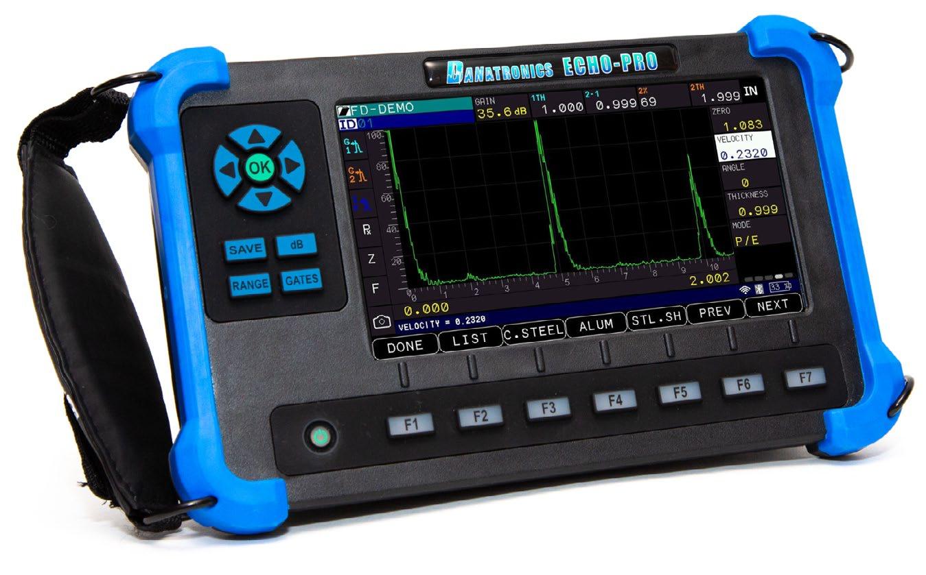


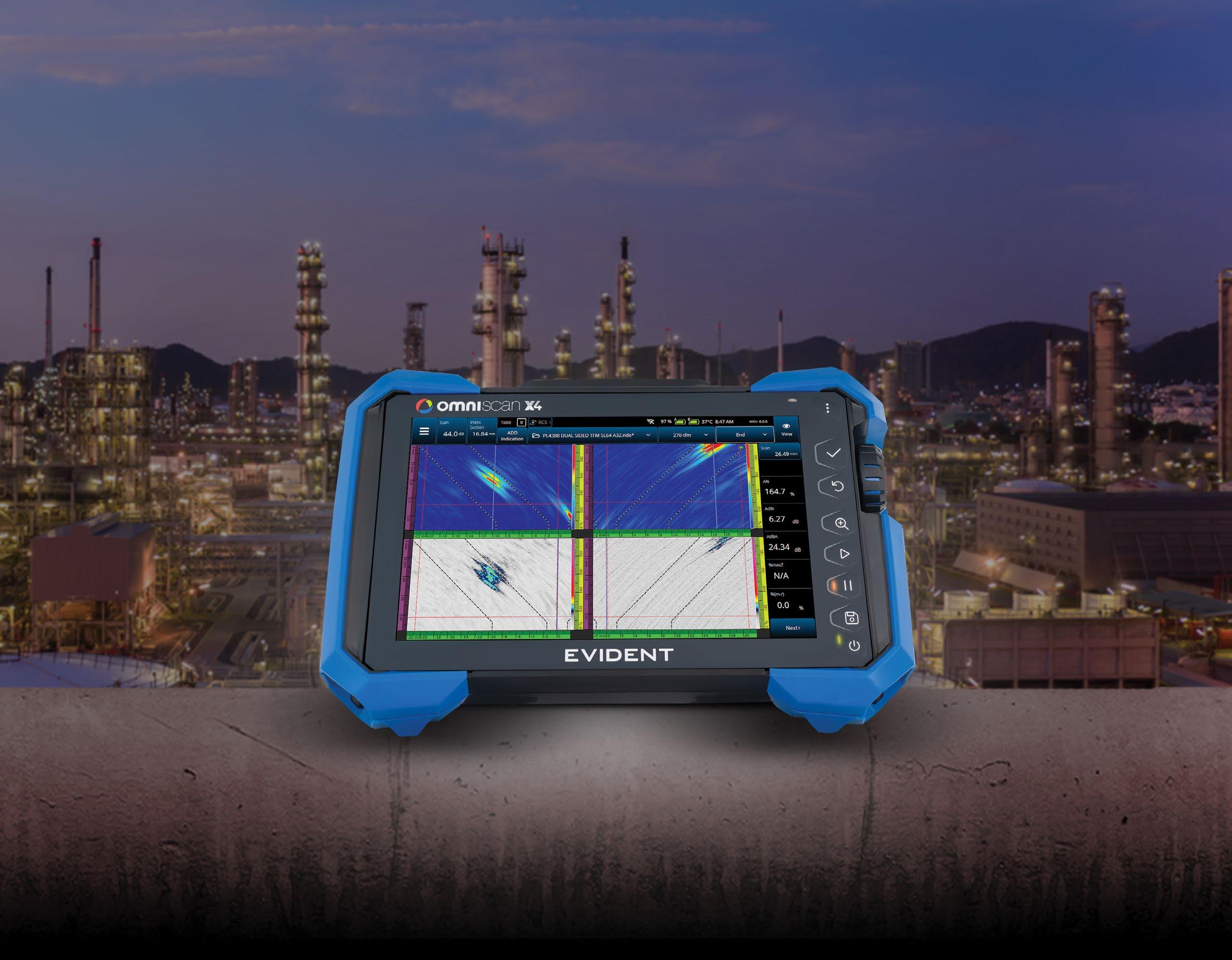
Be Ready for What’s Next
The New OmniScan™ X4 Flaw Detector
Engineered for Speed & Simplicity
Advanced imaging technology and an easy-to-use interface allow users of all skill levels to perform fast, accurate inspections—boosting performance and streamlining workflows.
Proven to Perform, Trusted to Deliver
An all-in-one imaging platform, coupled with unmatched portability and versatility, delivers exceptional results in even the most challenging inspection environments.
Designed to Evolve with Your Needs
With free quarterly software updates, the OmniScan X4 empowers you to continuously adapt to future inspection needs—ensuring that you’re always ready for what’s next.