

INDUSTRIAL
THE OFFICIAL JOURNAL OF THE AUSTRALIAN INSTITUTE FOR NON-DESTRUCTIVE TESTING
RADIOGRAPHY ULTRASONICS EDDY CURRENT PENETRANT MAGNETIC PARTICLE VIBRATION ANALYSIS LUBRICATION ANALYSIS THERMOGRAPHY ACOUSTIC EMISSION
Inspection starts
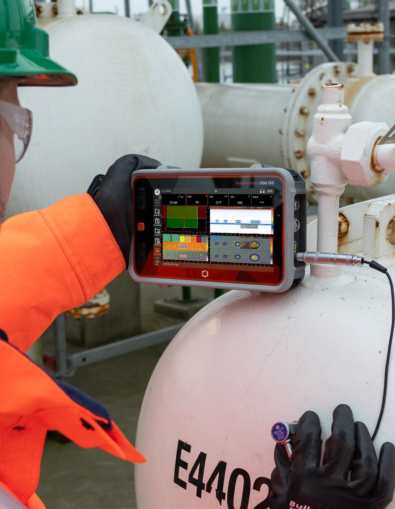
• App integration
• Guided calibration for quick setup
• IP 67 rating to withstand toughest conditions
• Advanced and customizable Data Recorder
• Encoded B/C scan capability
Krautkrämer USM 100 continues to deliver unparalleled performance and reliability - at a competitive price.

President's Message
I am pleased to announce that the Australian Institute for Non-Destructive Testing (AINDT) has received formal approval from JAS-ANZ to transition our personnel certification scheme from ISO 9712:2012 to the updated ISO 9712:2021 standard.

This long-anticipated milestone follows several years of preparation and brings our certification practices in line with current international expectations and industry best practices.
As many of you will know, ISO 9712, the key standard underpinning NDT personnel certification, was revised in 2021. The AINDT Board of Directors, Certification Board, and Federal Office identified the transition as a strategic priority early on. However, the complexity of implementation and the formal approval process required more time than initially anticipated. On behalf of the Board, I extend our apologies for any inconvenience this delay may have caused.
The 2021 revision introduced a number of important updates, including:
• Clearer delineation of responsibilities for Certification Bodies, Authorised Qualifying Bodies, examination centres, and employers
• Revised and expanded definitions
• New requirements for examiners and referees
• Updates to training and experience criteria
• Modified visual acuity testing procedures
• Enhanced examination requirements
• Provision for psychometric evaluation at the discretion of the Certification Body
• Revisions to certification documents and renewal processes
• Updates to the structured credit system for Level 3 recertification
• New annexes covering testing techniques (Annex F) and psychometric principles (Annex G)
• Other technical and editorial changes
Successfully incorporating these revisions into our certification scheme has been a substantial undertaking.
I would like to express my sincere gratitude to the Transition Committee, particularly its Chair for the meticulous work undertaken to analyse the new standard, identify system gaps, and drive the necessary changes.
I also acknowledge the Certification Board for their measured, practical insights, and the Federal Office for their continued diligence and member support throughout this process.
While our aim has been a smooth, transparent, and member-focused transition, we recognise there have been challenges. These have included ambiguity in the updated certification process, limited awareness of recent changes among applicants, and at times, insufficient communication. We sincerely regret these issues and are working to address them proactively.
As we now move forward with the implementation of the updated certification scheme, our focus remains on maintaining the competence of AINDT certified personnel as a cornerstone of quality, safety, and reliability in the NDT profession.
AINDT remains committed to upholding rigorous standards, without introducing unnecessary complexity, and we continue to welcome constructive feedback from our members. Your input is vital to ensuring the robustness and relevance of our certification framework.
The transition to ISO 9712:2021 is an important step forward for all stakeholders. We thank our members and certificate holders for their patience and professionalism during this time. As always, we ask that communication with our office staff remain respectful as they work diligently to support all inquiries.
Should you have any questions or concerns, please do not hesitate to contact the AINDT Federal Office.
Your feedback will help guide our continued improvement and service to the NDT community.
Warm regards,
Joshua Morris, President Australian Institute for Non-destructive Testing
Joshua Morris


President:
Immediate
Vice
Secretariat
CEO:
President
Vice
Treasurer
Secretary
Production Sally Wood Design Alarna O’Connell
AINDT
PO Box 52, Parkville Vic 3052
P: (03) 9486 9267
www.aindt.com.au
E: federaloffice@aindt.com.au
ADVERTISING
AINDT Federal Office
P: (03) 9486 9267
E: sally@wordly.com.au
INSTRUCTIONS TO AUTHORS OF TECHNICAL ARTICLES
Manuscripts should be submitted in electronic form:
1. in word
2. typed with single spacing
3. with figures as tif or jpeg files at better than 300dpi
Manuscripts should include:
1. symbols and abbreviations conforming to recognised standards; metric units (SI)
2. references listed, after the text, in the order in which they occur in the paper
3. references indicated in the text by arabic numerals in square brackets
4. tables and figures numbered separately but consecutively with Arabic numerals and brief, descriptive titles
5. a reference in the text to all tables and figures
6. graphs and diagrams made with lines of sufficient thickness to reproduce well
7. titles and address of authors
Procedure for submission of manuscripts:
1. articles should be sent to: journal@aindt.com.au
2. manuscripts will be submitted to referees who will remain anonymous
3. reprints of each paper will be supplied free to the author
Published by:
The Australian Institute for Non-Destructive Testing, PO Box 52, Parkville, Vic 3052 Australia
ISSN: 2203-2940
A Message from the CEO
Iso 9712:2021 Transition: What’s changing and how to prepare.

Following JAS-ANZ approval, AINDT is pleased to announce that we will transition our personnel certification scheme from ISO 9712:2012 to ISO 9712:2021 effective Monday 15 September. This column sets out the core mechanics so that candidates, certificate holders and employers can plan with confidence.
Guidance and Documents
AINDT’s Guide to Certification has been reviewed with the transition in mind for some time. The updated edition will be published ahead of Monday 15 September with the aim is clarity: plain-English explanations of requirements by level, method and sector, with examples of acceptable evidence.
What Stays the Same
• Both editions continue to specify requirements for the qualification and certification of industrial NDT (Non Destructive Testing) personnel.
• Both maintain the three levels of personnel qualification (Levels I, II, III), and the system remains aligned with a third-party, centrally administered certification model.
• The overall validity period for certification remains five years in both editions, with recertification or renewal required at that point.
What Changes
The 2021 edition of ISO 9712 strengthens ongoing competence maintenance and offers clearer pathways for renewal.
Of particular note for Level 2 renewals, in addition to vision and colour visions tests, and provision of verifiable documentary evidence of continued satisfactory work in the method and sector, you will now need to do one of:
• Successful completion of practical exam; or
• Successful Completion of Structured Credit System with supporting documented evidence.
The practical examination route is familiar: a focused, current-competence check aligned to the certified method and sector. The Structured Credit System route recognises structured professional development and practice (captured and verified in a credit framework) consistent with ISO 9712:2021 and AINDT scheme documents. Full definitions, acceptable activities and minimum thresholds will be provided in the updated Guide and on the AINDT website.
Timing and Applicability
• Applications assessed on or after Monday 15 September will be assessed against ISO 9712:2021.
• Existing certificates remain valid to their printed expiry dates. There is no change to current validity solely because the scheme has transitioned.
• Candidates already scheduled for examinations around the transition date will receive direct confirmation of the applicable requirements.
What Candidates Should Do Now
1. Review your renewal window. If your Level 2 renewal falls after 15 September, decide early whether you will pursue the practical exam or the Structured Credit System route.
2. Gather evidence. For either route, maintain clear records: recent vision and colour-vision results, logged work demonstrating continued satisfactory practice and, if using the credit route, documented CPD and other qualifying activities as specified in the Guide.
Stuart Norman
3. Book early. Examination and verification capacity will be managed to minimise delays; early bookings help keep industry moving.
4. Check the forms. Use the updated application and renewal forms once published to avoid processing delays.
Benefits for Industry
The 2021 edition of ISO 9712 enhances the link between certification and current, demonstrable competence. Employers gain stronger assurance. Certified personnel gain flexible, clearly-defined options to maintain status. Clients benefit from inspections performed under a scheme aligned to present-day risk, technology and regulatory expectations. In a market facing capacity constraints, the dual pathway for Level 2 renewals (practical exam or structured credits) adds flexibility without diluting standards.
Thank you to the Transition Committee, the Certification Board and the Federal Office for the careful, member-first work that brought us to this point. The move to ISO 9712:2021 is a measured change that keeps Australian certification credible, current and competitive—exactly what industry expects from AINDT.

ISO 9712:2021 transition: What’s changing and how to prepare
Following JAS-ANZ approval, AINDT is pleased to announce that we are transitioning from ISO 9712:2012 to ISO 9712:2021 effective Monday 15 September.
Guidance and Documents
AINDT’s Guide to Certification has been reviewed with the transition in mind for some time. The updated edition will be published on our website ahead of Monday 15 September. The aim is clarity: plain-English explanations of requirements by level, method and sector, with examples of acceptable evidence.
What Stays the Same
• Both editions continue to specify requirements for the qualification and certification of industrial NDT (Non Destructive Testing) personnel.
• Both maintain the three levels of personnel qualification (Levels I, II, III), and the system remains aligned with a third-party, centrally administered certification model.
• The overall validity period for certification remains five years in both editions, with recertification or renewal required at that point.
What Changes
The 2021 edition of ISO 9712 strengthens ongoing competence maintenance and offers clearer pathways for renewal.
Of particular note for Level 2 renewals, in addition to vision and colour visions tests, and provision of verifiable documentary evidence of continued satisfactory work in the method and sector, you will now need to do one of:
• Successful completion of practical exam; or
• Successful Completion of Structured Credit System with supporting documented evidence.
The practical examination route is familiar: a focused, current-competence check aligned to the certified method and sector. The Structured Credit System route recognises structured professional development and practice (captured and verified in a credit framework) consistent with ISO 9712:2021 and AINDT scheme documents. The updated Guide to Certification will be available on the AINDT website.
Timing and Applicability
• Applications assessed on or after Monday 15 September will be assessed against ISO 9712:2021.

• Existing certificates remain valid to their printed expiry dates. There is no change to current validity solely because the scheme has transitioned.
• Candidates already scheduled for examinations around the transition date will receive direct confirmation of the applicable requirements.
What Candidates Should Do Now
1. Review your renewal window. If your Level 2 renewal falls after 15 September, decide early whether you will pursue the practical exam or the Structured Credit System route.
2. Gather evidence. For either route, maintain clear records: recent vision and colour-vision results, logged work demonstrating continued satisfactory practice and, if using the credit route, documented CPD and other qualifying activities as specified in the Guide.
3. Book early. Examination and verification capacity will be managed to minimise delays; early bookings help keep industry moving.
4. Check the forms via our website. Use the updated application and renewal forms once published to avoid processing delays.
For further information, contact: federaloffice@aindt.com.au

Member List
July
2025
The AINDT is a national peak body that promotes the professional practices of non-destructive testing and condition monitoring personnel. Our mission is to provide members, industry and the community with independent and professional service in relation to the science and practice of non-destructive testing.
Through the work of our state branches and federal office, AINDT is committed to fostering a community of professionals and organisations dedicated to the fields of non-destructive testing, engineering, and materials and quality testing.
We offer a tiered membership structure, inviting businesses to enhance their professional standing and industry influence by becoming a Company, Corporate, or Sustaining member. Our memberships unlock a suite of benefits, including marketing opportunities, heightened support, streamlined staff certification management, and much more. AINDT would like to thank the companies below for their valued support.
SUSTAINING MEMBERS
ATTAR
D R May Inspections
EnerMech
SRG Industrial Pty Ltd
Intertek
SUPPORTING MEMBERS
Chevron
COMPANY MEMBERS
NSW
ARL Laboratory Services Pty Ltd (Yennora)
AXT Pty Ltd
Barry Evans Lifting World
Bluescope Steel (Port Kembla)
ENDETEK
Hot Engineering
HVT Inspection Services
Magnetic Analysis Aust Pty Ltd
NBQC & Inspections Services
NDT Equipment Sales Pty Ltd
Nobel Engineering Services
Reliance Hexham
RPG Australia
Russell Fraser Sales Pty Ltd
Simplifi Nii P/L
SmartChem Industries Pty Ltd
Sonix NDT Pty Ltd
Thermal Imaging Services (AUS)
QLD
AXS Pty Ltd (Mackay
CORPORATE
MEMBERS
Azure NDT Quality Services Pty Ltd
Bureau Veritas Australia
Chemetall (Australasia) Pty Ltd
Evident Australia Pty Ltd
GFS NDT
Hofco Oilfield Services
IRISNDT
OMS Engineering Pty Ltd
SafeRad SE Asia Pty Ltd
School of Engineering
TR Pty Ltd
Equipment Direct International Pty Ltd
Industrial Mining Inspection Solutions
International Tube Testing Pty Ltd
Metal Testing Pty Ltd
M-Test Mackay Pty Ltd
Queensland Alumina Limited
Testing Inspection and Calibration Services
VIC / TAS
ABEN Technical Services
ATCL
Defence Science and Techology Organisation (DSTO – Fishermans Bend)
Gippsland NDT Services Pty Ltd
Global Inspections & Engineering Services Pty Ltd
ITest NDT
LMATS Pty Ltd (Williamstown)
NATA
OMS Software Pty Ltd
SA / NT
ASC Pty Ltd
Kuzer Technical
QMS
Red Earth NDT Pty Ltd
WA
Alliance Solutions Group
Applecross Electrical & Testing Service
Asset Reliability Inspections Pty Ltd
Assurity NDT & Consulting
GoldFields NDT
Hofmann Engineering
ICM Training Solutions
Integrity Engineering Solutions
MJ Engineering Inspection Services (Welshpool)
NDT Instruments Pty Ltd
Vertech
Optiflow Pty Ltd
Portable Scientific Pty Ltd
Weld Integrity
Wood – Asset Performance
Optimisation

RENEW YOUR MEMBERSHIP

RENEW FOR REWARDS: STAY A STEP AHEAD WITH 2025-2026 AINDT MEMBERSHIP
Whether you're looking to enhance your knowledge, expand your network, or influence industry standards, AINDT is your gateway to success. Connect with top professionals and thought leaders in an environment that celebrates innovation and progress. Just some of the member benefits are outlined below.
Regular editions of the AINDT Journal (6 per year)
Substantial discounts on certification fees and expenses
Access to our online portal and resources
Eligibility for exam and industry service awards
A host of networking opportunities, including branch events, workshops, seminars, and our conference
Exclusive Corporate Member benefits like free and discounted advertising rates, and technical advice
MEMBERSHIPS ARE NOW DUE
Non-Destructive Testing Certification Board Update
Earlier this year, the Non-Destructive Testing Certification Board (NDT CB) was inundated with Applications for Special Consideration for Certification extensions.
I would like to remind all candidates that Certification under ISO 9712 is for a fixed five-year term only. We cannot, and will not, extend certification past five years, under any circumstances.
The AINDT has always been generous to our certification holders in allowing a further 12 months past certification expiry to complete a renewal and recertification application.
However, please remember:
• Once a certificate has expired, it is no longer valid, regardless of the reason.
• Any NDT method performed after the expiry date of a NDT method certification is classified as being carried out by an uncertified person. This may lead to code or specification non-compliance, as well as possible questions around insurance coverage and in some cases non-compliance with legislation requirements.
• Expiry of a level 3 certification does not mean you step down to level 2 certification, and expiry of a level 2 certification does not mean you step down to level 1 certification.
• The 12-month grace period is to finalise recertification, not to continue practicing.
• Allowing expired certificate holders to continue working would undermine the system’s integrity.
• Applications that are received after five years (within the 12 month grace period) will only receive the remainder of the next five-year period from the expiry date. This prevents a scenario where someone tries to game the system to try and receive up to six years from a five-year certification.
• Special Consideration Applications will only be considered for up to a further three months past the 12mth grace period (maximum of 15 months past expiry). Applications for Special Consideration should be supported with evidence such as a Medical Certificate.
The NDT CB was quite lenient towards experience hours and examination dates for the two COVID years (2020 –2021), for both recertification and renewal applications and exams. Specifically for those candidates that were in states with extended lockdowns, as well as candidates who could not travel to sit exams.
It has now been over five years since the pandemic officially started in Australia (January 2020) and this

leniency for the COVID years is quickly coming to an end. If candidates were short hours for these years, there was an expectation that some effort would be made to catch up hours in the following years.
We received several applications for the NDT CB applications sub-committee that was recently advertised. Three were selected and accepted by the NDT CB. We welcome them to their new roles on the committee and look forward to training them over the coming months. Thank you to the new volunteers for their commitment in time to a critical part of the institute and thank you to all the others that applied to assist. It is great to see the support from the NDT industry for the AINDT NDT CB.
We have also had a very high response for nominations for the NDT CB. We will be reviewing the applications over the next month and will look to invite new two new candidates to the November CB meeting.
Thanks Barry and Mark NDTCB Chairman and Vice Chair
Condition Monitoring Training Centres
Unlock the future of your career with top-tier condition monitoring training from trusted providers.
These training centres have earned the endorsement of AINDT, aligning perfectly with the national syllabi approved by the AINDT Certification Board. This ensures that you receive the highest standard of education and training.
To maximise your learning experience, AINDT recommends obtaining a copy of the training module—either directly from the training provider or by downloading it from the AINDT website. This will ensure you are well-prepared for your course.
For those seeking certification, it's crucial to successfully complete the specified training program and required training hours outlined in ISO18436. This is essential for achieving certification in your desired conditioning monitoring method, category, and industry sector. All examinations are conducted by the AINDT. For exam dates and further details, please contact AINDT via: federaloffice@aindt.com.au.
Elevate your skills and advance your career with the industry's best training and certification programs.
Victoria
Industrial Precision Instruments
A: Unit 12, 634-644 Mitcham Road, Vermont 3133
T: 1300 781 701
E: training@ipi-inst.com.au
W: ipi-inst.com.au
IR Technology Australia
A: 39-45 James Street, Lara 3212
T: 0418 569 698
E: erik.t@bigpond.com
W: irta.com.au
University of Melbourne
A: Parkville 3010
T: 03 9810 3348
E: claudine.evans@unimelb.edu.au
W: unimelb.edu.au
Wood – Asset Performance Optimisation
A: Level 3, 171 Collins Street, Melbourne 3000
T: 08 6314 2000 or (08) 6314 2280
E: svt.bu.training@woodplc.com
W: woodplc.com
Western Australia
ICM Training Solutions
A: 45 Delawney Street, Balcatta 6021
T: 0419 993 233
E: rainingacademy@icmt.com.au
W: icmt.com.au
SRG Training Academy
A: 109 Bannister Road, Canning Vale 6155
T: 08 9232 0300
E: trainingacademy@srgglobal.com
W: srgglobal.com
Wood – Asset Performance Optimisation
A: Level 1, 240 St Georges Terrace, Perth 6000
T: (08) 6314 2000 or (08) 6314 2280
E: svt.bu.training@woodplc.com
W: woodplc.com
Queensland
Advanced Infrared Resources Australia AIRA
A: PO Box 372, Hervey Bay 4655
T: 0467 565 836
E: jeff@irtau.com.au
W: irtau.com.au
Machinery Diagnostics Institute
A: 16 Wheeler Avenue, Gracemere 4702
T: 0499881 294
E: training@mcsturbo.com
W: mdiaustralia.com
SRG Training Academy
A: 7 Brisbane Road, Riverview 4303
T: 07 3816 5500
E: training@mcsturbo.com
W: mcsturbo.com
Wood – Asset Performance Optimisation
A: Level 20, 127 Creek Street, Brisbane 4000
T: (08) 6314 2000 or (08) 6314 2280
E: svt.bu.training@woodplc.com
W: woodplc.com
Authorised Qualifying Bodies
AQBs are authorised to offer AINDT-approved training and initial and recertification examinations in any Australian state, at any time throughout the year.
The AINDT also conducts scheduled examination rounds twice yearly, with dates advertised in The Industrial Eye and the AINDT e-newsletter.
While the AINDT strives to notify certificate holders of impending certification expirations, it remains the responsibility of the certificate holder to initiate the renewal and recertification process before their certification expires. Please note that late fees apply to overdue certification applications.
South Australia
Kuzer Technical
T: 1300 199 086
E: info@kuzer.com
W: kuzer.com
NDT methods, levels, and industry sectors offered:
• Magnetic Particle Level 1, 2 and 3 Multisector (ISO 9712)
• Dye Penetrant Level 1, 2 and 3 Multisector (ISO 9712)
• Ultrasonics Level 1, General Engineering (ISO 9712)
• Ultrasonics 2 and 3 Welds (ISO 9712)
• Phased Array Level 2 and 3 Multisector (ISO 9712)
• Time Of Flight Diffraction Level 2 and 3 Multisector (ISO 9712)
• Radiographic Testing Level 2 and 3 Welds (ISO 9712)
• Visual Testing Level 1 and 2 Multisector (ISO 9712)
• Eddy Current Level 1, 2 and 3 Multisector (ISO 9712)
• Level 3 Basic Exam Prep (ISO 9712)
• OCTG drill pipe inspection
• Material Science in NDT – Multisector
• NDT for Managers & Engineers
• Radiation Safety (exceeding the syllabus of national module EA612)
Victoria
ATTAR
T: 03 9574 6144
E: training@attar.com.au
W: attar.com.au
NDT methods, levels, and industry sectors offered:
• Computed and Digital Radiography 2, 3
• Ultrasonic Testing 1,2,3 Welds, Casting, Wrought,
• Aerospace, Thickness
• Radiographic Testing 2,3 Welds, Casting, Aerospace
• Magnetic Particle Testing 1,2,3 Multisector, Aerospace
• Penetrant Testing 1,2,3 Multisector, Aerospace
• Eddy Current Testing 2,3 Multisector, Aerospace
• Magnetic Flux Leakage 2
• Tank Bottom Testing
• Phased Array levels 2 and 3 Ultrasonics 2 Multisector
• Visual/Optical Testing 2 Multisector
• Time of Flight Diffraction (TOFD) levels 2 and 3 Welds
• Heat Treatment
• ISO 9712 UT Level 2 Corrosion/Erosion Detection and Mapping (CDM)
Western Australia
ATTAR
T: 03 9574 6144
E: training@attar.com.au
W: attar.com.au
NDT methods, levels, and industry sectors offered:
• Computed and Digital Radiography 2, 3
• Ultrasonic Testing 1, 2,3 Welds, Casting, Wrought,
• Aerospace, Thickness
• Radiographic Testing 2,3 Welds, Casting, Aerospace
• Magnetic Particle Testing 1,2,3 Multisector, Aerospace
• Penetrant Testing 1,2,3 Multisector, Aerospace
• Eddy Current Testing 2,3 Multisector, Aerospace
• Magnetic Flux Leakage 2
• Tank Bottom Testing
• Phased Array 2, 3 Ultrasonics 2 Multisector
• Visual/Optical Testing 2 Multisector
• Time of Flight Diffraction (TOFD) 2, 3 Welds
• Heat Treatment
• ISO 9712 UT Level 2 Corrosion/Erosion Detection and Mapping (CDM)
SRG Training Academy
T: 08 9232 0300
E: trainingacademy@srgglobal.com
W: srgglobal.com
NDT methods, levels, and industry sectors offered:
• Ultrasonic Testing 1,2 Welds
• Magnetic Particle Testing 1,2 Multisector
• Penetrant Testing 1,2 Multisector
• Phased Array Ultrasonic Testing 2 Multisector
Queensland
Protecs Global
T: 07 3492 9213
E: hamed.madani@protecsglobal.com.au
W: protecsglobal.com.au
NDT methods, levels, and industry sectors offered:
• Ultrasonic Testing 1 ( General Engineering) 2 Welds
• Magnetic Particle Testing, 2 Multisector
• Penetrant Testing, 2 Multisector
Highest Marks – 2025 Awards (for the Year 2024)
Each year, AINDT recognises outstanding achievement in certification examinations, celebrating the dedication, skill, and commitment of candidates who achieve the highest percentage pass marks across a range of examinations.
The 2025 Awards honour those who excelled in the 2024 examination year, setting the benchmark for technical excellence and professional knowledge in the NDT industry. Congratulations to all our award recipients.
SmartChem - Highest Percentage Pass Mark in the AINDT Level 2 General Penetrant Theory Examination in the Year 2024
Nelson Perez Arias, Victoria
SmartChem- Highest Percentage Pass Mark in the AINDT Level 2 General Magnetic Theory Examination in the Year 2024
Lewis Gale, New South Wales
Chemetall Magnetic Particle Award - Highest Percentage Pass Mark in the AINDT Level 2 Magnetic Particle Practical Examination in the Year 2024
Christian Agena, New South Wales
Chemetall Penetrant Award - Highest Percentage Pass Mark in the AINDT Level 2 Penetrant Practical Examination in the Year 2024
James O’Neil, Victoria
AINDT Award Penetrant Academic Excellence Award - Highest Percentage Pass Mark in the AINDT Level 2 Overall Exam Results (General, Specific and Practical) Penetrant Examination in the Year 2024
Justin Nogarotto, Victoria
Smartchem Magnetic Particle Academic Excellence Award - Highest Percentage Pass Mark in the AINDT Level 2 Overall Exam Results (General, Specific and Practical) Magnetic Particle Examination in the Year 2024
Lewis Gale, New South Wales
Baker Hughes Ultrasonic Award - Highest Percentage Pass Mark in the AINDT Level 2 Ultrasonic General Examination in the Year 2024
Theophilus Hayford, New South Wales
Baker Hughes Radiography Award - Highest Percentage Pass Mark in the AINDT Level 2 Radiography Practical Examination in the Year 2024
Aaron Lotstra, South Australia
LMATS Pty Ltd Radiographic Award: Highest Percentage Pass Mark in the AINDT Level 2 Best Overall Exam Result (General, Specific and Practical) Radiographic Examination in the Year 2024
Aaron Lotstra, South Australia

Olympus Phrased Array Ultrasonic Award - Highest Percentage Pass Mark in the AINDT Level 2 Specific and Practical Examination in the Year 2024
Matthew Shield, Queensland
Olympus Time Of Flight Diffraction Award- Highest Percentage Pass Mark for Overall in the AINDT Level 2 Examination in the Year 2023
Jan Basson, Queensland
OMS Software Pty Ltd Award - Highest Percentage Pass Mark in the AINDT Level 2 UT 2 Overall Exam Results (General, Specific and Practical
Ravel Matthews, Western Australia
Endetek Eddy Current Academic Excellence Award - Highest Percentage Pass Mark in the AINDT Level 2 Overall Exam Results (General, Specific and Practical)
Eddy Current Examination in the Year 2023
Mehdi Kianidehkian, Victoria
Duerr NDT/EN DE TEK RT CR/DR- Highest Percentage Pass Mark for Overall in the AINDT Level 2 Examination in the Year 2024
Hindraws Matti, New South Wales
Queensland Branch Update
Strong Regional Turnout and New Leadership
Mark a Memorable AGM in Bundaberg
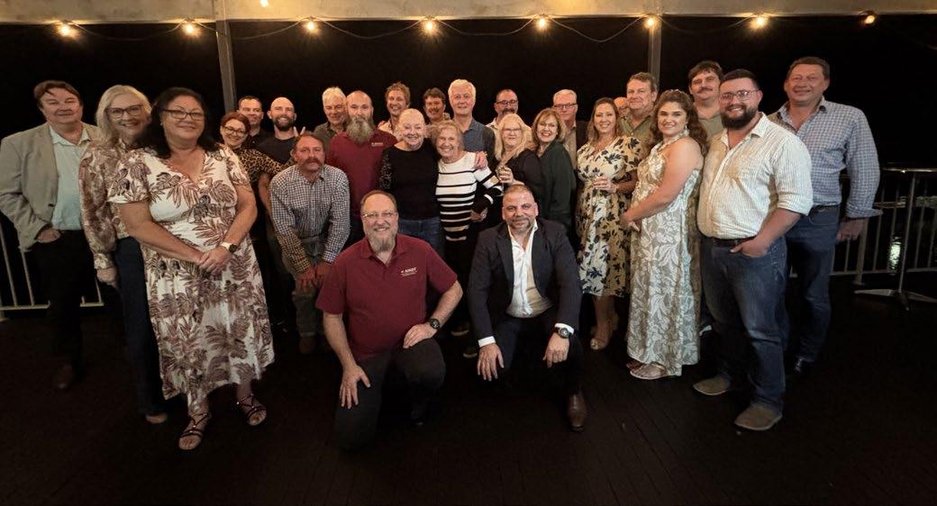
The AINDT Queensland Branch proudly held its Annual General Meeting (AGM) on 26 July 26 at the Burnett Riverside Hotel in Bundaberg—an event that brought together members from across the state in an inspiring display of commitment to our NDT community.
We were thrilled to see such a strong turnout from regional Queensland, which highlights the unity and enthusiasm that continues to drive our branch forward.
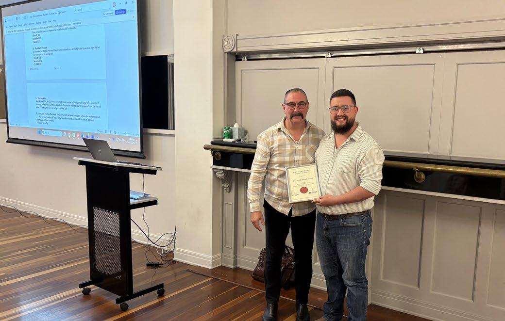
Recognition of Excellence: AINDT Award Winners
We proudly congratulate two NDT professionals from Queensland for their outstanding achievements, recognised as winners of prestigious AINDT awards. Their dedication and contributions have elevated our branch and showcased Queensland's leadership in the NDT community.
Congratulations to our Winners:
Arno Basson
AINDT Level 2 TOFD examination 2024
Matt Shields
AINDT Level 2 specific and practical Exam2024.
A special thanks goes to Evident for their generous Gold Sponsorship of the event. We deeply appreciate the continued support of Graham Maxwell and Sean Fogarty, who have been long-standing contributors to the success of AINDT QLD events.
The AGM also marked a time of transition and renewal for the branch leadership. We extend our heartfelt gratitude to our retiring councillors for their dedication and service over the years. Your efforts have laid the foundation for our continued growth. At the same time, we are excited to welcome our new councillors, whose fresh perspectives and energy we look forward to harnessing in the months ahead.
With our new leadership in place, the Queensland Branch is now gearing up for an exciting calendar of technical nights and social events designed to keep our community connected, informed, and inspired.
Stay tuned, there’s more to come as we continue to grow together in the spirit of collaboration and excellence.
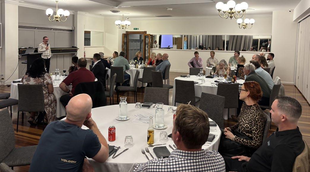

Caption TBC
Victoria and Tasmania Branch Update

The AINDT Victoria and Tasmania Branch continues to build momentum in 2025. In the coming months, two significant events will bring our members together - a mental health presentation tailored to professionals in technical industries, and our AGM Dinner, which promises to be a key social and professional highlight of the year.
The council, following its 606th meeting in June, is commitment to strengthening the member experience. Our upcoming events reflect that vision, with a focus on mental health, connection, and celebration.
Online Mental Health Presentation
On Friday, 1 August 2025, we hosted a virtual mental health session, presented by Matt Glover and Cam Semmens of MGA Counselling. This session addressed the unique pressures of our field and offering strategies for resilience, awareness, and support.
This event was FREE for all members, and we encouraged wide participation. Mental wellbeing is increasingly recognised as essential to long-term performance and work satisfaction.
Celebrating Together - 2025 AGM Dinner
We look forward to welcoming members and guests to the 2025 AINDT Branch AGM Dinner on Friday 5 September. This year’s dinner will be held at Brewmanity in South Melbourne, running from 6:00pm until midnight. The event will include a formal AGM segment, followed by dinner and opportunities to reconnect.
Tickets are priced at $30 for members and $50 for nonmembers, with honorary members and their partners invited free of charge. Guests will enjoy great food, a bar tab and the chance to participate in door prize draws. In support of the evening, the branch is offering several
sponsorship opportunities – please reach out if you’re interested:
• Tier 1 sponsors will receive a speaking opportunity, logo placement on all promotional material, prominent event signage, and a post-event feature in this journal.
• Tier 2 sponsors will be acknowledged through branding, flyers, and inclusion in the post-event article.
• Door prize sponsors will be recognised during the event and in our coverage, with donations welcomed in the form of wine, vouchers, or relevant industry prizes.
The AGM Dinner not only reflects on the past year but is also an important platform for networking and recognising the efforts of our branch members and contributors.
Listening to Our Members - Survey Feedback
As part of our continued efforts, we recently distributed a short survey to gather feedback on our events, communication, and direction. We are grateful to those who took the time to share their thoughts and help shape the future of our programs.
To those who participated - thank you. Your input is invaluable. If you haven’t yet completed the survey, there’s still time to do so. As a token of our appreciation, all respondents will go into the draw to win two movie tickets.
Looking Forward
Our branch council volunteers their time to improve the NDT industry; to assist us we encourage all members to share ideas for events or improvements - and most importantly, to turn up! We look forward to seeing many of you online in August and in person at the AGM Dinner in September.
Western Australia Branch Update

Energy and Mining Collaboration SpeedNetworking
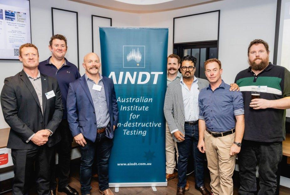
What a great night at the Energy and Mining Collaboration speed-networking event hosted by the Professional Networking Institute at The Claremont Hotel in early May. With over 200 attendees, the sold-out event was packed with representatives from so many different industries. The Australian Institute for NonDestructive Testing is proud to have joined as one of the collaborating organisations, offering free tickets to our members.
With topics, trends and issues relevant to the many different groups in the region, the Professional Networking Institute (PNI) is partnering with other industry associations across the Western Australia resources industry, from mining and renewables, through to oil and gas.
The aims of the collaboration event was to:
• Introduce the members of each industry group to each other, to amplify the impact and results of professional networking
• Further develop both the professional networking skills and professional networks of attendees, as well as their relationships in adjacent markets
The evening format was in typical Sundowner-style, but also included facilitated speed-networking across associations and the ability for people to gain additional information on the other resources associations.
Representing the AINDT from the Western Australia Branch at our stand on the night were (L-R below) Richard Stocker, Josh Wilkinson, Josh Morris, Ahmed
Jahanzaib, Jay McDonnell Nathan Lenane and Mark Welland.
We’re hoping to continue representing the AINDT annually, increasing the profile of NDT as an industry.
Edith Cowan University and Fraunhofer Webinars
The Western Australia Branch recently announced a new professional relationship with Edith Cowan University (ECU) after discovering their interest in NDT technologies and a joint venture they have with German research and development company Fraunhofer.
ECU and Fraunhofer recently delivered three free webinars on NDT technologies that they are researching and deploying to industry. The webinars were advertised to all AINDT members and it was positive seeing members from most states of Australia dialling in. Each of the webinars is out lined.
Wireless Sensor Systems for Safe Offshore Structures - CoMoBelt®
Presenters: Dr. -Ing. Lars Schubert and Dr Bianca Weihnacht
The CoMoBelt® sensor ring developed by IKTS is a permanent monitoring system for offshore wind turbine foundations. It reduces the need for costly on- site operations and maintenance by being attached to heavily loaded areas like welded seams. This setup minimises the impact of external biomaterial growth and eliminates the need for divers to manually clean measuring points.
The system includes ultrasonic transducers that act as sensors or actuators, capable of withstanding harsh underwater conditions. Energy supply and data readout are managed by Remote Operating Vehicles (ROVs), which transfer data wirelessly to diagnostic devices and then via cable to technicians on a ship. This technology enhances reliability and extends the service life of the CoMoBelt® system by eliminating the need for plug connections.
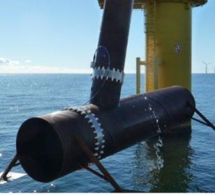
Key takeaway: The use of techniques similar to combining LRUT and Acoustic Emission was interesting with this technology.
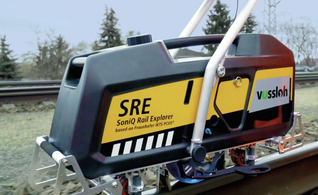
Mobile Ultrasonic Rail Testing System
Presenters: Prof. Dr. -Ing. Henning Heuer
The SoniQ Rail Explorer (SRE developed for Vossloh Rail Services GmbH at Fraunhofer IKTS, enhances rail network maintenance by combining multiple nondestructive testing systems into a single ultrasonic device. It gathers diverse data in one run, integrating video, ultrasonic signals, and GPS information for accurate analysis. Supported by Al, it improves pattern recognition and maintenance strategies.
Key takeaway: The multi-channel and combination of angle and zero degree probes in the rail testing unit was unique and beneficial to fast and detailed data collection.
From Fibre to Componen
Presenters: Dr Killian Tschӧke and Dr Martin Schulze
Fraunhofer IKTS develops automated ultrasonic and eddy current testing technologies to detect manufacturing defects in carbon fibre components. Their seminar covers systems for testing high-performance carbon fibre fabrics and monitoring H2 pressure vessels. They offer a complete development chain for monitoring systems, from sensor design to integration and testing.
Key takeaway: The eddy current on composites was new and exciting to see. It had not been widely recognised as being implemented in real-world scenarios prior to this presentation.
The AINDT, and specifically the Western Australia Branch, would like to extend our gratitude to Fraunhofer IKTS presenters and ECU for bringing these webinars to Australia. We look forward to seeing more of the Fraunhofer innovation projects over the coming years.


A DAY TO RELAX, CATCH UP WITH COLLEAGUES AND LET YOUR COMPETITIVE JUICES FLOW!
ANNUAL GOLFDAY
THURSDAY, 04th December 2025
Collier Park Golf Course
First Tee off - 11AM
Go Further, Learn More: Apply for AINDT’s Travel Grant
AINDT is inviting eligible members to take their learning global through the AINDT Overseas Conference Grant—often called the Travel Grant.
Established by Federal Council in 1980, the Grant exists for one clear reason: to accelerate the professional development of our members through international engagement in NDT and Condition Monitoring.
“Our industry advances when our people do,” said Stuart Norman, CEO of AINDT. “This Grant helps members get in the room—overseas—where the latest research, techniques and standards are being debated, demonstrated and adopted. The benefits return to the individual, their employer and the broader AINDT community.”
What the Grant Supports
The Travel Grant is designed to help fund overseas study tours and attendance at international conferences with a clear focus on NDT or CM. It is not intended for general travel or non-NDT/CM activities. Funding may be provided in part or in full, subject to annual budget and the number of eligible applicants. In any given year, up to two applicants may be approved. The maximum value is $2,000 for an individual.
“We’re very deliberate about focus and impact,” noted Norman. “We want to support members who will get handson with emerging technologies, connect with technical leaders, and bring those insights home, whether that’s improving inspection reliability, advancing training, or informing Australian standards work.”
Who Can Apply
To be eligible, applicants must:
• Be a financial AINDT member for at least three consecutive years before applying.
• Be actively employed beyond routine testing, for example in technique or equipment development, research evaluation, or interpreting results for fitnessfor-purpose decisions.
• Demonstrate that both their training and personal qualities mean the Grant will deliver value to the member and to AINDT.
• Not have previously received the Grant (it is awarded once per member).

How to Apply (and What to Include)
Start by contacting the AINDT Federal Office to confirm eligibility and initiate your application. Your submission should outline:
• The event, itinerary or study tour you propose to undertake
• A clear statement of benefit—to you and to AINDT
• A detailed budget of anticipated costs
• Evidence of active contribution to NDT/CM
Applications are reviewed by the AINDT Board of Directors at a scheduled meeting; urgent requests may be considered via electronic or postal ballot. All decisions are formally recorded.
Your Commitment as a Recipient
Recipients must use the funds only for the approved purpose (registration, travel, accommodation). Within four weeks of returning, recipients submit a written report for publication in Industrial Eye.
Ready to Go Global?
If you meet the criteria and have a compelling plan, this is your moment. Reach out to the AINDT Federal Office to confirm eligibility and begin your application via federaloffice@aindt.com.au
“We’re proud to back members who are curious, purposeful and generous with what they learn,” said Norman. “If that sounds like you, apply. Bring the world’s best ideas home to Australia, and let’s keep lifting the bar together.”
SHAPE THE

Join the vibrant team of volunteers at your local state branch and turn your passion for progress into action. Volunteer with us and connect with a community of professionals dedicated to making a difference in our industry. W H Y V O L U N T E E R ?
Network with industry leaders and peers
Develop professional skills and gain unique experiences Influence the direction of our industry and contribute to meaningful change aindt.com.au


Standards Update
The ISO Standard Committee meetings were held in Niagara Falls, Canada during the last quarter. Australia was represented at these meetings on the Main Committee, as well as Method Committees for Certification, Ultrasonic, Eddy Current, Thermography and Acoustic Emission.
As explained in the previous Standards Update, the ISO Standards Committees looked closely at evolving NDT methods such as PAUT FMC / TFM and PAET together with the possibility of setting up a new ISO Standard Committee for (MFL) Magnetic Flux Leakage. This new Committee would cover corrosion scanning techniques used on in-service tank floors, piping and tubes, as well as steel mill inspections of new materials. As the proposed MFL Standards Committee is in its infancy, it is expected that the Committee will be operational by the end of 2026, provided that all ISO members are in agreement.
MT007 did not meet as proposed in June to review aged Australian Standards. This meeting was deferred, and expected to occur at the end of August. Online voting would be undertaken by MT007 Committee Members in order to continue the process of potentially adopting ISO Standards where no Australian Standard currently exists.
Other ISO Standard activities are as follows. For Vote
Project: ISO 22232-1:2020 : Non-destructive testing — Characterization and verification of ultrasonic test equipment — Part 1: Instruments
Project: ISO 22232-2:2020 : Non-destructive testing — Characterization and verification of ultrasonic test equipment — Part 2: Probes
Project: ISO/CD 25222-2 : Non-destructive testing - Characterization and verification of ultrasonic aircoupled equipment — Part 2: Probes
Project: ISO 12713:1998 : Non-destructive testing — Acoustic emission inspection — Primary calibration of transducers
Project: ISO 17643:2015 (Ed 2, vers 2): Non-destructive testing of welds — Eddy current testing of welds by complex-plane analysis
Project: ISO 23277:2015 (Ed 2, vers 2) Non-destructive testing of welds — Penetrant testing — Acceptance levels
Project: ISO 23278:2015 (Ed 2, vers 2) Non-destructive testing of welds — Magnetic particle testing — Acceptance levels
Please contact me using the details below if you have any questions or require further information and I will reply at the first opportunity.
Angelo Zaccari MT007 Standards Chairperson. angelo.zaccari@outlook.com

Thermography in Action
This is a change of pace from our usual articles for Industrial Eye, in that it’s not directly related to thermography.
But there are certainly lessons to be learned here for electrical thermographers, and any other trade professional. This is the story of an electrical incident that, very fortunately, resulted in no lasting injury or harm, but might easily have gone the other way.
What Happened?
Electricians were dispatched to make some minor modifications to an existing electrical switchboard, in pretty average condition, at a small industrial premises. The switchboard was de-energised at the main switch, as it should be, and the fuse links removed from the fuse bases directly above the electricity meter. So far so good, all normal procedure, the installation was safe and de-energised.
Then, in a sudden lapse in judgement, the electrician decided to loosen the meter panel to inspect behind it and confirm that if anything was mounted to the panel they were not going to inadvertently put a fixing or a drill bit through a live cable.
Unfortunately what the electrician did not realise is that, while they were expecting the fuses to be “back wired” (where a fully insulated cable enters the fully insulated fuse base, with no danger of contact with live parts), they were in fact “stud wired” (where a large, and very much uninsulated stud, protrudes out the back of the fuse base and a lugged cable is bolted onto the stud).
The panel was heavier than expected and immediately dropped a few centimetres down and to the left. Quickly realising that the situation was not as he’d anticipated and that removing the panel was not a great idea in the first instance, the electrician then attempted to move the panel back into place.
The stud on the top of the B phase fuse made contact with the metal mounting frame, and there was a resultant arc flash. The electrician’s hand was directly in the line of fire, and they sustained some first-degree burns to the top of their fingers. Power to the site and an adjacent building was disrupted as the HV drop-out fuse for the pole-top transformer blew.
Again, this was an installation and maintenance task, not a condition monitoring inspection, but it doesn’t take much imagination to see how similar misadventure could visit an electrical thermographer.
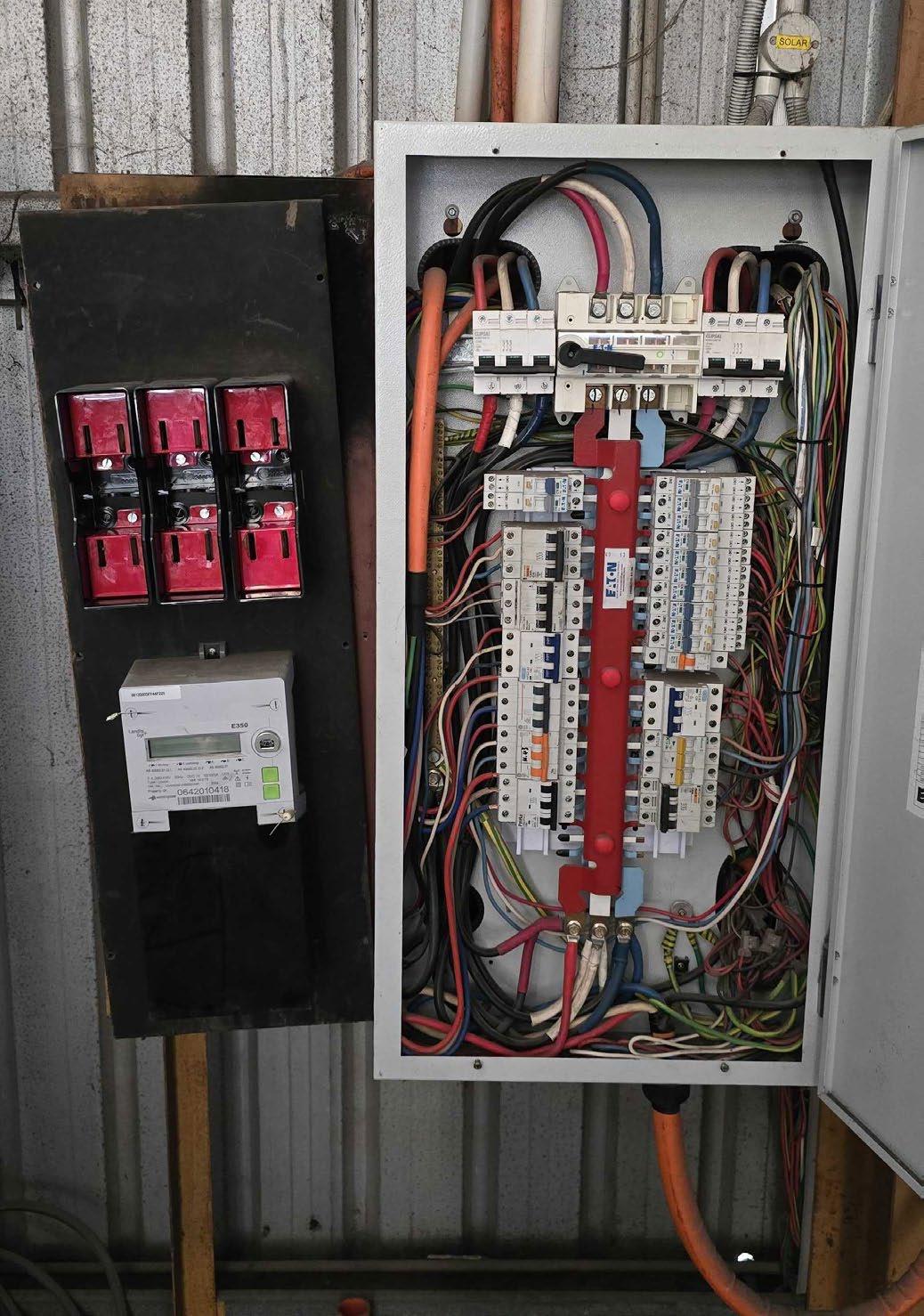
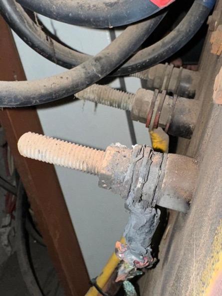
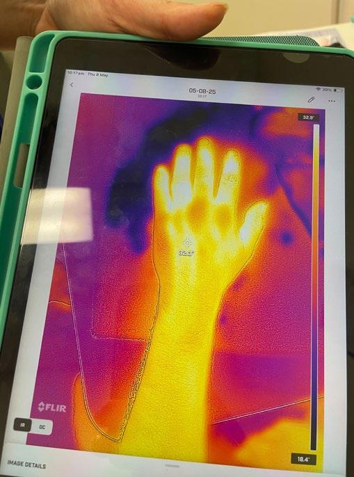
Figure 1. The electrical switchboard
Figure 2. The offending stud
Figure 3. Bonus thermogram of the injured hand (visible light image not provided due to privacy)
Post-Incident Analysis
Naturally, aside from the need to re-energise the site and provide medical treatment for the injured electrician, we needed to conduct a thorough postincident analysis to find out what had gone wrong. Particularly as we are an organisation where awareness of arc flash hazards should be part of our DNA.
Here’s what we found:
1. An obvious, albeit quite understandable, error of judgement.
2. Over-delegation. The work had been quoted and scoped by one manager, and then handed off to another to brief the attending electrician. This meant that advice on how to manage the risk, like “beware of the uninsulated studs behind those fuses”, was not fully conveyed.
3. General complacency. We usually work on “big” sites and “big” switchboards, so surely this tiny little one comes with tiny little risks, right? Wrong.
4. Lack of knowledge of the components. The electrician did not know, and could not reasonably have been expected to know, that 200amp “red spot” style fuse bases are always stud connected.
5. Undesirable installation conditions. This was a nasty old switchboard in a nasty old building and the repair was an undesirable work-around to solve a client issue that should really have been solved with a switchboard upgrade/replacement. We should never have agreed to do this in the first place, but we were trying too hard to be accommodating.
6. Arc flash PPE was not being worn. In a cruel irony, not long previously we had issued arc flash gloves to all our field service technicians (prior to that arc flash PPE had been standard issue for electrical thermographers, with “communal” arc flash PPE available at the workshop for use as required). But…
7. ... we had yet to provide any formal training or guidance on when to use the PPE.
We also completed the calculations to analyse the incident energy and found that, at the working distance in question (10cm), it was approximately 16.4 calories per cm2. This agrees with the extent of the injury. Notable that at a slightly closer distance of 5cm, the incident energy would have been 65 calories per cm2. This likely would have cost the injured electrician their hand. It's impossible to overstate the importance of distance and line-of-fire in arc flash; if you’re twice as far away, you receive one quarter as much energy. However, conversely, in our analysis we did find some things we’d done right:
1. There was a safety spotter present, trained in first aid, who was able to render immediate first aid and provide transport to the nearest ER.
2. The electrician received immediate medical treatment.
3. The incident was immediately reported to the network operator in line with our legal obligations.
4. Other personnel stepped in and worked tirelessly to bring the installation back online.
5. We had issued arc flash gloves to protect against exactly this eventuality.
Fortunately, there was no permanent injury, the electrician returned to work soon afterwards, the site was energised the next day, and the customer and end-user were understanding of the fact that this was largely due to an unfortunate confluence of events and that occasionally on site, things just go wrong.
What Did We Learn (or Change) Moving Forward?
The big lesson for us here was that sometimes done is better than perfect. We’d delayed delivering training on arc flash PPE because we had spent months in “analysis paralysis” trying to perfect it. That was a mistake. We immediately developed a comprehensive arc flash training and hazard mitigation program and delivered this to all our field service technicians within two weeks, not just our electrical thermographers as had been the original policy.
Similarly, we quickly deployed complete arc flash PPE kits to all our field service vehicles. We took great pains to ensure the kits were not generic off-the-shelf but consisted of the best possible equipment we could find that was both comfortable for daily use, practical, and did not inhibit mobility or vision to the point that it reduced the consequences of an arc flash hazard but increased the likelihood.
Moreover, this underscored important lessons that are extremely relevant to any electrical thermographer:
• Always have a safety spotter
• Always trust your instincts if it feels sketchy
• Always work within your abilities and experience
• Always use the appropriate PPE
• Never remove a panel with equipment mounted on it that is not hinged
• Never be afraid to call it off if it doesn’t feel safe. You can just say no.
• Even the most mundane task, on the most mundane site, can go sideways in the blink of an eye.
Member Profile: Samad Asghary
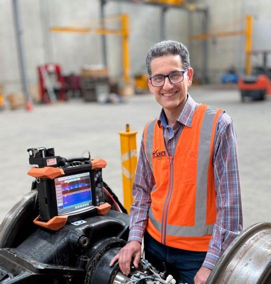
Samad Asghary
Since migrating to Australia in 2014 to join LMATS, Samad Asghary has built an impressive career defined by technical excellence, problem-solving, and a passion for advancing non-destructive testing (NDT). Today, as LMATS’ Director of Research, Innovation & Quality, he leads initiatives that push the boundaries of NDT techniques, develops new methodologies, and ensures the highest standards of quality management.
With a career spanning more than 25 years, Samad’s journey began in Iran in 1997, where his background in applied physics found a natural home in the NDT profession. His work has taken him across industries, from conducting advanced eddy current testing on massive power plant condensers to mentoring the next generation of NDT professionals. Along the way, he has earned multiple Level 3 certifications, pioneered innovative testing solutions, and built a reputation for integrity, accuracy, and reliability.
In this Member Q&A, Samad shares his professional milestones, the mentors who have shaped his career, and the advice he would give to newcomers to the industry. He also reflects on the importance of continuous learning, staying at the forefront of technological developments, and upholding the core values that ensure trust in inspection results.
Where do you work? Describe your job.
I was offered a position by LMATS and migrated to Australia in 2014. Since then, I have advanced my NDT career at LMATS, assuming a variety of roles, including conventional and advanced NDT inspector, NDT Level III consultant and technical controller, quality manager, and, most recently, Director of Research, Innovation and Quality. In addition to my current responsibilities, I continue to carry out my previous roles as needed.
My primary responsibilities encompass:
• Supervising the quality management system and providing direction to the quality manager and other personnel regarding system requirements.
• Leading research and development initiatives focused on innovative techniques and the necessary equipment.
• Designing and implementing new NDT methods and techniques, and preparing the corresponding procedures.
• Offering expert consultation to clients for resolving their NDT-related challenges.
• Conducting training for NDT personnel.
Can you share your journey into the NDT industry? What motivated you to take on a career in NDT?
Upon completing my degree in applied physics and fulfilling my mandatory two-year military service, I was offered a position in 1997 with an NDT services company in Iran, facilitated through a close friend. At the outset of my career, I found the field both intellectually stimulating and highly relevant to my academic training. I specialised in three methods: Eddy Current (ET), Ultrasonic Testing (UT), and Magnetic Particle Testing (MT), obtaining my Level 2 certifications and gaining practical experience across a diverse range of industries.
In 2003, I successfully completed the Level 3 certification exams and commenced providing Level 3 services, which included the development of innovative NDT methods, conducting research and development, offering expert consultation, and training personnel.
The field of NDT offers a unique opportunity to apply theoretical principles from physics in a practical context, while simultaneously presenting new and evolving challenges. These intellectual challenges have consistently fuelled my curiosity and served as a powerful motivator for my continued progression in this field.
Who or what has influenced you most professionally?
I had the privilege of learning from several Level 3 mentors from the UK; however, it was D. Dulay from NDT Consultants who had the most significant influence on me, owing to his extensive knowledge and expertise in the NDT field.
What has been the most interesting project you’ve worked on and why?
I have been involved in numerous projects across various sites and industries; however, one of the most remarkable projects was at a thermal power plant, where I conducted eddy current testing on a large condenser with nearly 15,000 tubes. I successfully completed the project on schedule, and the results were exceptionally accurate, particularly with regard to the tubes that were pulled out.
Given that many of the tubes exhibited pitting corrosion exceeding the plugging criteria, the client expressed great satisfaction with the timely execution of the test, as it enabled us to identify the defects and prevent an expensive, unscheduled shutdown and unplanned maintenance.
What advice would you give to someone just starting their career in the NDT industry?
In my opinion, individuals seeking success in the NDT field should possess the following qualities:
1. A strong foundation in basic physics,
2. A keen interest in learning and a passion for challenges,
3. A high degree of patience
What has been your greatest professional achievement?
One of my greatest professional achievements in NDT field was successfully passing the ASNT NDT Level 3 exams in Eddy Current (ET), Ultrasonic Testing (UT), and Magnetic Particle Testing (MT) methods, all at once, approximately five years after commencing my NDT career.
This achievement marked a significant milestone in my professional development, as it required a deep understanding of complex NDT techniques and the ability to apply them in real-world situations.
The successful completion of these exams not only validated my technical expertise but also allowed me to take on more advanced roles in NDT, providing consultation, developing innovative testing methods, and training others in the industry.
How has being a member of AINDT benefited you professionally or personally?
Upon relocating to Australia in 2014, bringing with me 17 years of extensive experience in the NDT field, I joined the Australian Institute for NDT (AINDT).
This affiliation provided a vital platform for networking with NDT professionals nationwide, greatly enhancing my understanding of the local industry.
Engaging with these professionals facilitated my integration into the Australian NDT sector, enabling me to adapt effectively to its distinct standards and requirements.
What are the top 3 things on your bucket list?
I am pursuing additional professional goals, including mastering advanced NDT techniques such as FMC/ TFM and PCI in ultrasonic testing, as well as expanding my expertise in infrared/thermal testing and probably in shearography. Given the rapid advancement of technology in the field, it is essential for me to remain
up-to-date in order to contribute to the industry and provide maximum support to our clients.
What is your favourite
• Food: As the most Iranian Ghormeh Sabzi
• Song: I love Fereydoun Farrokhzad and Freddie Mercury songs
• Sport: Table tennis and mountain climbing
If you could be famous, what would it be for?
If I were to become known in the NDT field, I would want it to be for my commitment to quality, honesty, and reliability, as well as my ability to solve complex technical problems.
These values are essential to building trust with clients and ensuring the integrity of inspection outcomes. I take pride in delivering accurate and transparent results, and in providing practical, effective solutions to inspection challenges.
If you could meet anyone—alive or dead— who would it be?
Cyrus the Great
What is your pet peeve?
Complacency in following procedures is a major pet peeve of mine. Cutting corners or making assumptions can compromise both safety and reliability, which goes against everything the profession stands for.
What is your top tip for NDT excellence?
My top tip for NDT excellence is to always combine technical accuracy with professional integrity.
No matter how advanced the technique or equipment, the outcome is only as reliable as the inspector’s commitment to following procedures, verifying results, and reporting findings honestly.
Attention to detail, continuous learning, and never becoming complacent are key to maintaining excellence in this field.
Ultrasonic Phased Array Inspection of CRA and Dissimilar Welds: A Practical Guide
Corrosion-resistant alloys (CRAs) and dissimilar welds are essential in oil & gas pipelines, refineries, and power generation systems.
BY SABRI BABA
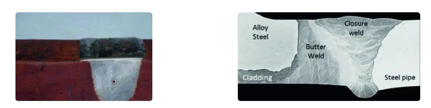
Designed to withstand aggressive service environments, these welds often join materials with markedly different acoustic properties—e.g., stainless steel overlays on carbon steel or nickel alloy claddings (Figure 1).
Beyond corrosion protection, dissimilar welds or austenitic filler materials are used to achieve tailorengineered properties: providing high temperature resistance, toughness, wear resistance, or strength precisely where needed. However, the same variations in physical characteristics that make these structures so effective also create challenges for inspection. Coarse, anisotropic grain structures can scatter or attenuate ultrasonic signals, while dissimilar interfaces introduce mode conversions and reflections that complicate interpretation.
Advances in phased array ultrasonic testing (PAUT) and inspection modalities such as the transmit-receive longitudinal (TRL) technique are helping inspectors overcome these obstacles. By delivering sharper views of the weld structure and improving flaw characterization, these technologies enable higher confidence in weld integrity—even with demanding CRAs and dissimilar
containing a weld, both the metal–metal interface and the coarse-grained structure of the weld can cause partial reflection (backscatter) and refraction of the waves. In dissimilar welds, abrupt changes in acoustic impedance at the fusion line generate complex signal paths that distort or mask indications.
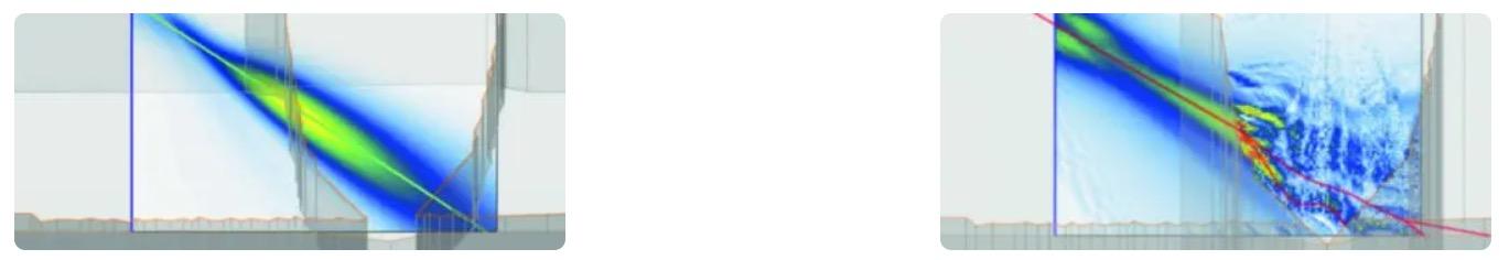
Meanwhile, the large, often columnar grains typical of CRA and austenitic welds scatter and redirect ultrasonic energy, introducing anisotropy that further skews and attenuates the beam (Figure 2). These combined effects reduce the amplitude and reliability of echoes returning from flaws, increasing the risk of missed or misinterpreted indications.
Distribution of
Where Conventional UT Inspection Falls Short
Conventional ultrasonic testing (UT) has long been a cornerstone of weld inspection. However, when it comes to CRAs and dissimilar metal welds, standard UT methods encounter several well-known obstacles.
Metal-Metal Interface and Grain Size
When an ultrasonic beam travels through a component
energy in
Comparison of ultrasonic wave performance in a weld with similar materials (left) versus a dissimilar weld (right). At the metal–metal interface, partial reflection, refraction, and scattering cause skewing and attenuation of the ultrasonic beam, complicating flaw detection.
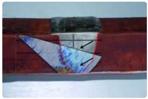
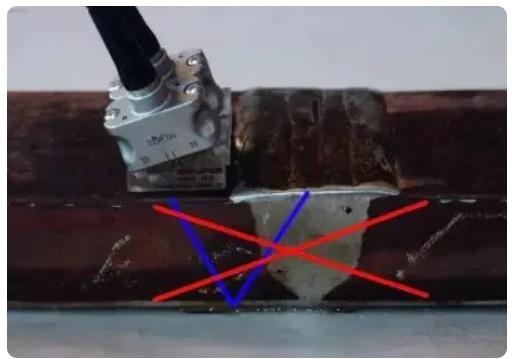
In a practical example of this issue, Figure 3 shows how the highly reflective interface between the carbon steel parent material and an Inconel weld dramatically affects ultrasonic propagation. In this case, side-drilled holes placed to verify inspection sensitivity could not be detected using conventional shear waves—highlighting the need to adapt the inspection strategy, such as by selecting alternative wave modes.
Figure 1: Common welds used in cladded pipes, including a dissimilar weld material (left) and a weld used to join two different materials (right).
Figure 2.
ultrasonic
welds.
Attenuation
Even when ultrasonic waves successfully penetrate dissimilar or austenitic welds, they often experience significant attenuation. The coarse, multi-directional grain structures common to these welds absorb and scatter energy as the sound propagates, progressively reducing beam strength with depth.
In dissimilar welds, each constituent material has its own characteristic attenuation factor and may also be inhomogeneous. As a result, ultrasonic waves traveling through these joints experience varying degrees of energy loss depending on their angle of incidence and the depth within the weld. This means that attenuation is not uniform across the weld volume; different paths will diminish the signal to different extents.
Ideally, a sensitivity calibration would yield consistent responses for identical flaws located at different depths or positions within the weld. However, in practice, compensating for the variable attenuation in dissimilar or coarse-grained welds is challenging. Achieving perfect, uniform sensitivity throughout the weld and its heat-affected zone is generally not possible. Consequently, sizing and evaluating indications requires careful consideration of these inherent variations in sensitivity.
Optimizing CRA and Dissimilar Weld Inspections
Optimizing the ultrasonic inspection of austenitic and dissimilar welds involves many of the same fundamental parameters as inspections of conventional carbon steel joints. However, each of these steps must be examined more closely to ensure reliable detection and characterization of indications in these more challenging materials. Key aspects include:
1. Scan planning
• Propagation mode: longitudinal vs. shear waves
• Transmit-receive longitudinal (TRL) technique
• Ensuring full weld coverage
• Focal method and probe selection
• Instrument capabilities
2. Calibration
• Selection of the calibration block
• Wedge delay calibration
• Sensitivity calibration
• Detection level adjustment
3. Sizing and depth tolerance of indications
4. Coupling
The following sections explore each of these considerations in turn, highlighting common pitfalls and offering practical guidance for achieving efficient, accurate inspections of complex welds.
1. Scan Planning
Propagation Mode: Longitudinal vs. Shear Waves
A critical factor when inspecting challenging welds is selecting the appropriate ultrasonic wave mode. In general, longitudinal waves transmit energy more effectively through welds compared to shear waves, making them better suited to navigating the acoustic complexities of dissimilar or austenitic joints.
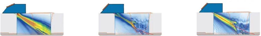
Digital modelling (Figure 4) illustrates that ultrasonic beams experience significantly more skewing when shear waves are employed, increasing the risk of missed or distorted indications. Although longitudinal waves can still be influenced by reflected shear components, their superior transmission energy makes them the preferred choice for inspecting dissimilar weld materials.
Transmit-Receive Longitudinal (TRL) Technique
Another key decision in setting up an effective inspection is whether to use one or two transducers. While welds can be examined using a single transducer in a pulse-echo arrangement (where the same element both transmits and receives the ultrasonic signal), this approach is not ideal for dissimilar or austenitic welds. The inherent grain noise and backscatter in these materials can overwhelm pulse-echo signals, reducing flaw detectability.
The transmit-receive longitudinal (TRL) technique, also known as a pitch-catch setup, mitigates this issue by employing separate transducers for transmission and reception. In this arrangement, signals are primarily collected from the area where the two beams intersect, significantly lowering background noise. Additionally, since the pulser and receiver are separated, no internal dampening material is needed, allowing for smaller wedges. This lets the probe approach closer to the weld, increasing sensitivity.
Figure 3. Shear wave UT scan at 5 MHz over a dissimilar weld. The sidedrilled holes (black arrows) intended to verify inspection sensitivity could not be detected due to the reflective interface between the carbon steel and Inconel, highlighting the limitations of conventional shear wave techniques.
Figure 4. Computer models of ultrasonic beam propagation. Comparing 2.25 MHz longitudinal waves (left) with 1 MHz shear waves (center) and 2.25 MHz shear waves (right).
When applied with longitudinal waves, the TRL technique combines reduced interference with deeper penetration than shear waves, resulting in cleaner signals with a lower noise floor (Figure 5). The method can be executed using conventional UT transducers or phased array probes.
Phased array offers further advantages by enabling sectorial scanning, which provides imaging capabilities and full coverage of the weld without repeatedly repositioning the probe. This flexibility, paired with precise beam steering, helps simplify inspections and improve detection—though in some cases, multiple offsets from the weld centerline may still be needed to achieve the optimal beam orientation relative to potential indications.
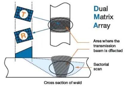
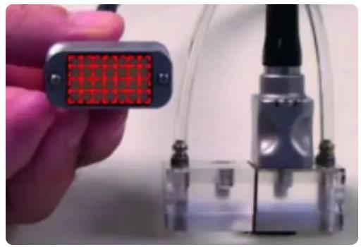
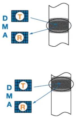
Modern flaw detection platforms such as the Evident OmniScan™ X4 and QuickScan iX™ PA+ provide the flexibility needed to implement the TRL technique in combination with advanced phased array methods. This approach can be performed using dual matrix array (DMA) probes, which incorporate two transducer arrays—each built from multiple rows and columns of active elements (Figure 6).
DMA probes are available in a variety of frequencies, sizes, and element counts, making them adaptable to a broad range of inspection scenarios. Their two-dimensional arrangement enables several key capabilities when paired with phased array systems:
• Sectorial scans for comprehensive coverage of the weld volume (Figure 5)
• Beam skewing to steer the UT beam off-axis and interrogate flaws from multiple angles (Figure 7)
• Curvature correction to adjust for curved surfaces, maintaining optimal beam incidence (Figure 8)
These combined functionalities help overcome the inherent complexities of inspecting CRA and dissimilar welds, supporting more reliable detection and characterization of indications.
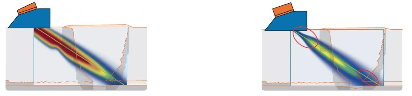
Figure 5: Illustration of the TRL technique. TRL harnesses separate transmitting and receiving probes to reduce noise.
Figure 6: A Dual Matrix Array (DMA) Probe. The probe consists of two transducers containing 28 phased array elements each.
Figure 7: Performing the TRL Technique with DMA Probes. Using the TRL technique with DMA probes offers the ability to steer the skew angle of the beam.
Figure 8: DMA Probes and Curvature. A DMA probe (right) better compensates for the curvature of the surface of a component—a smaller focus point provides better sensitivity.
Figure 9: A comparison of pulse echo versus TRL. Model of the energy of a pulse-echo transducer (left) compared to the TRL technique (right) and the resulting energy of the transmitter and the receiver beam.
Sensitivity and Coverage Considerations with TRL
One consequence of employing the TRL technique is a reduced volume in which sufficient acoustic energy is present to reliably detect flaws. As illustrated in Figure 9, meaningful signal strength is primarily confined to the region where the transmit and receive beams intersect. Compared to a pulse-echo arrangement, energy levels are significantly lower both before this crossing point and beyond it.
Figure 9 also highlights the TRL technique’s narrower depth of field. Just beneath and between the two transducers (prior to beam intersection) there is minimal to no energy, resulting in poor sensitivity. Beyond the crossing zone, sensitivity also drops off quickly due to the diverging far fields of each transducer.
Despite this, the focused nature of the TRL setup ensures that energy is concentrated precisely in the area of interest, effectively reducing noise levels relative to pulse-echo techniques. Additionally, the compact wedge design permits closer proximity to the weld, enhancing near-surface sensitivity and making the TRL approach well-suited for challenging weld inspections.
Ensuring Full Weld Coverage with TRL
Achieving complete weld coverage is critical when using the TRL technique. As Figure 9 illustrates, the inspection volume is inherently limited by the intersection of the transmit and receive beams, which means special care must be taken to ensure the entire weld is interrogated.
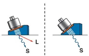
A particular challenge with longitudinalwave sectorial scans is that shear waves are simultaneously generated (Figure 10). Due to differences in wave velocity, these shear waves can interfere with the returning longitudinal signals, especially after reflections from the bottom surface, complicating interpretation of indications near the top of the weld.
Additionally, when a component features an internal cladding of a different material from the base metal, it

cap can be machined flush, and a secondary scan performed directly on top to ensure full volumetric coverage up to the weld centerline.
Figure 10: Simultaneous generation of longitudinal and shear waves. When longitudinal waves (L) are introduced into the material, shear waves (S) are also produced due to mode conversion, which can lead to interference in the inspection signal.
Figure 11: Impact of internal cladding on wave propagation. A CRA layer on the inner surface prevents longitudinal waves from cleanly bouncing off the back wall, reducing inspection effectiveness.
Figure 12: Surface and longitudinal wave paths. Left: longitudinal waves (red) penetrate while surface waves (green) travel along the surface. Right: surface wave propagation across the weld cap (red).
Focal Strategy and Probe Selection
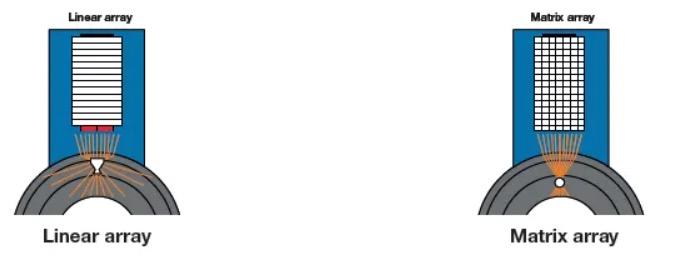
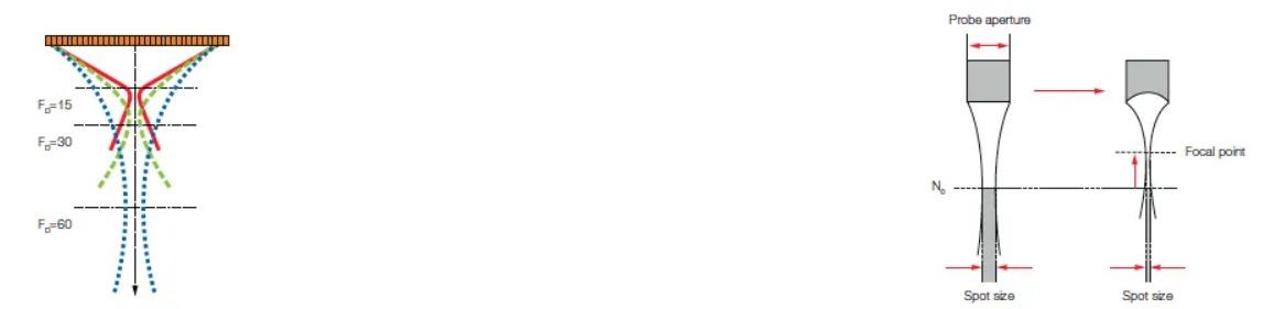
A crucial factor when selecting a phased array probe for weld inspection is matching the probe aperture and focal strategy to the application. Phased array systems offer a major advantage by enabling precise control over the ultrasonic beam’s spot size through electronic focusing, which directly influences sensitivity and sizing accuracy.
Adjusting the spot size allows inspectors to optimize detection at different depths: narrowing the focus improves sensitivity at the target zone, whether near the surface or deeper within the weld. Each probe also has a natural focal depth, known as the near field distance (N₀). To further refine this, electronic focusing (Figure 13, left) or mechanical lensing (Figure 13, right) can be used to concentrate energy precisely where it’s needed, shifting the focal point closer to the surface than the inherent N₀.
This level of control is especially valuable in complex weld geometries or when inspecting materials with variable acoustic properties, ensuring high-quality data throughout the inspection volume. However, for thicker components, simply lowering the focal plane via electronic focusing may not be sufficient. In these cases, a probe with a larger effective aperture is required to maintain sensitivity at greater depths. This can be achieved in two ways—either individually or in combination:
• Increasing the size of individual elements: Larger elements allow deeper penetration without demanding more powerful electronics to drive them. However, probes with bigger elements have reduced beam-steering capability, limiting their effectiveness for sectorial scans that are essential for fully covering the weld volume.
• Increasing the number of active elements: Using more elements to form the beam improves penetration while preserving steering accuracy. The trade-off is that the inspection instrument must support a larger active aperture—16 elements may be insufficient for these applications, necessitating systems with greater channel capacity.
This balance between probe design and system capability is critical to achieving optimal performance across a range of weld thicknesses and geometries.
Instrument Capabilities
When inspecting welds from both sides, an effective phased array system should be capable of driving multiple probes simultaneously to enable efficient single-pass coverage. In such cases, instruments with 128-channel phased array configurations are typically required.
To meet these demands, Evident has developed a range of phased array instruments (Figure 14), including the OmniScan X4, the QuickScan iX PA+, and probes designed to overcome the challenges of complex welds. The OmniScan X4 provides advanced phased array capabilities with expanded aperture support, while the QuickScan iX PA+ is designed for automated multiprobe scanning applications, delivering high-speed data acquisition and precise weld tracking.
For components up to 25 mm thick, a standard dual matrix array (DMA) probe operating at 4 MHz is often sufficient. However, for thicker sections or welds exhibiting larger grain structures (where maintaining adequate wave propagation becomes more challenging) a lower frequency probe (1.5 MHz or 2.25 MHz) with a larger active aperture is recommended.
These probes integrate seamlessly with both the OmniScan X4 and QuickScan iX platforms, ensuring the flexibility needed to adapt inspection setups for a wide range of weld geometries and material conditions.
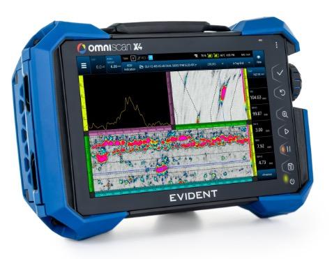
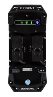
2. Calibration Selecting the Reference Block
Once the appropriate phased array equipment has been chosen, a robust calibration process must be established. Calibration is fundamental to ultrasonic inspections, and it begins with selecting a suitable
Setting a reference level based on a known reflector—typically a side-drilled hole—so real
Ensuring that different inspectors following the same procedure will achieve consistent results, and that identical calibration blocks can be produced for use across multiple operators or sites.
Figure 13: Phased array focusing methods. Electronic (left) and mechanical (right) focusing reduce spot size and shift the focal point closer to the probe, enhancing sensitivity at shallower depths.
Figure 14: Evident OmniScan X4 and QuickScan iX PA+. Advanced phased array systems capable of driving DMA probes for efficient inspection of dissimilar and CRA welds.
There are two primary options for a calibration block:
• A block made solely from the parent material, without any weld.
• A block fabricated from a production weld, similar to the welds under inspection.
While a block containing an actual weld offers a closer representation of inspection conditions, it introduces challenges for repeatability. Variations in weld microstructure can cause inconsistent attenuation and scattering, and beams traveling at different angles may encounter differing amounts of weld material. Additionally, the velocity of ultrasonic waves can vary with beam orientation, and slight differences in hole depth or block manufacturing can significantly impact sensitivity. These factors make it difficult to guarantee that two weld-based reference blocks will perform identically.
Conversely, a calibration block made from only the parent material ensures consistent acoustic properties (e.g., attenuation and velocity) across multiple blocks. This uniformity makes it easier to replicate sound paths and maintain reliable sensitivity levels throughout inspections.
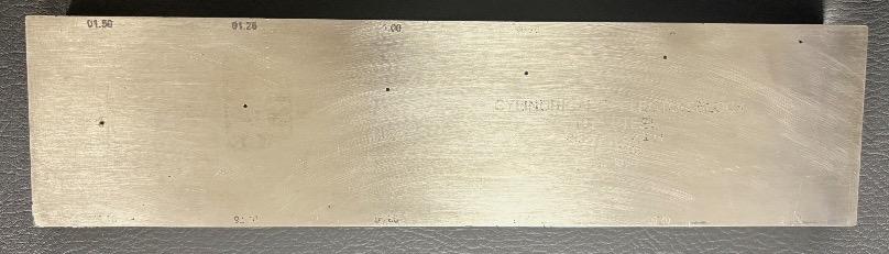
Wedge delay calibration
When a wedge is used to produce angled ultrasonic beams, the setup requires proper wedge delay calibration. This process is similar to standard pulseecho calibration and typically involves using a reference block with well-defined reflectors to establish the correct time offset.
Sensitivity calibration
In most inspections, two separate sensitivity calibrations are performed: one for the longitudinal waves that cover the main weld volume, and another for the surface waves that assess the near-surface region. Once repeatability is ensured by selecting an appropriate calibration block, sensitivity calibration can proceed using either a fixed gain or a time-corrected gain (TCG) approach.
TCG involves scanning side-drilled holes at various depths to adjust the gain over time, as shown in Figure 16. With carbon steel welds, this process is typically straightforward. However, in inhomogeneous or highly attenuative materials, especially when using techniques other than pulse-echo, TCG preparation can be challenging. Different sound paths through side-drilled holes may experience varying attenuation levels, leading to large gain adjustments that complicate calibration.
If TCG is not employed, a single reference reflector— often placed on the weld bevel—can serve as the calibration point. When TCG is used alongside the TRL technique, the reduced depth of field (the effective region of high energy, see Figure 17) means that overcompensating with gain is impractical. TCG points should be confined to the useful zone of each ultrasonic beam and aligned with the angles used in the sectorial scan. There’s no need to extend TCG calibration to deep regions that high-angle beams will never penetrate.
For surface wave calibration, the process is simpler. A notch on the outer diameter (OD-notch) is used, with the system adjusted to achieve an 80% amplitude response at varying distances between the probe and the notch.
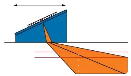
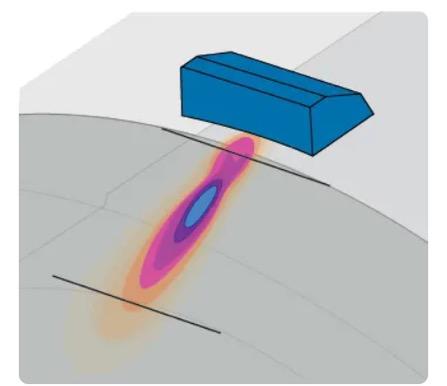
Detection Level
Once sensitivity calibration is complete—whether using a TCG curve or a fixed gain—the gain levels for both longitudinal and surface waves must still be fine-tuned to establish a practical reference. This is typically done by measuring well-characterized reflectors, such as real indications or flat-bottomed holes in a representative weld sample (Figure 18).
Proper gain adjustment is essential to minimize noise, ensuring that imaging modes like S-scan, B-scan, and C-scan deliver the highest possible signal-to-noise ratio (Figure 19). Cleaner scans not only improve flaw
Figure 15: A Calibration Block for UT Inspections
Figure 16: TCG calibration process. The phased array probe scans across a block with side-drilled holes to equalize the amplitude of all beams in a sectorial scan.
Figure 17: Limited area of TCG effectiveness. Illustration of the confined area where TCG can be effectively applied due to the focused energy of the ultrasonic beam.
visibility but also simplify interpretation, supporting faster and more reliable analysis.
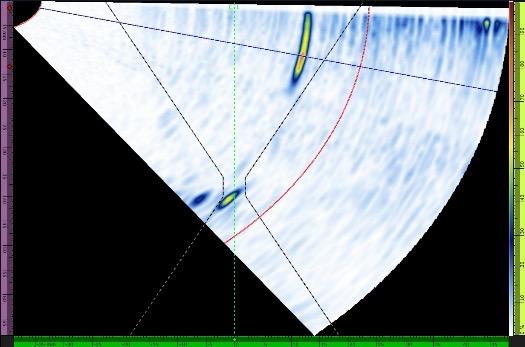
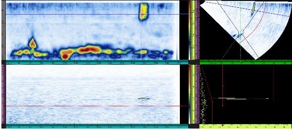
3. Sizing and Depth Tolerance of Indications
Determining the depth tolerance—the maximum acceptable deviation between measured and actual flaw depth—is especially important when inspecting welds that combine different materials. In these scenarios, ultrasonic energy can spread or deviate as it encounters varying acoustic properties, meaning the precise beam angle cannot always be guaranteed (Figure 20). This can introduce uncertainty into depth measurements.
Practically, operators often choose to oversize indications rather than risk underestimating them. However, excessive oversizing can inflate rejection rates unnecessarily. Investing in robust sizing validation— such as scanning multiple samples containing artificial reflectors that mimic expected flaw types, then macro-
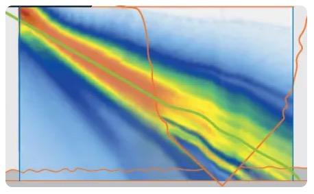
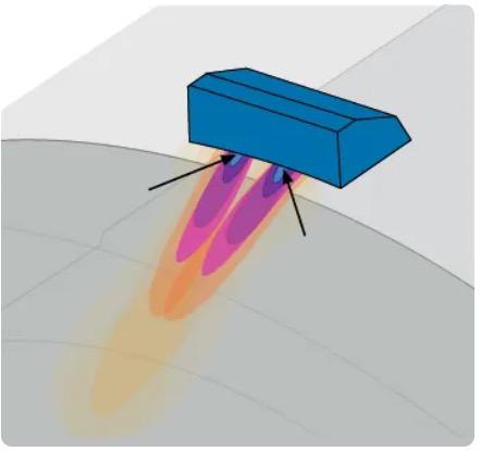
sectioning to confirm actual dimensions—helps optimize acceptance criteria and reduce false rejections.
4. Coupling
The final key element in establishing an effective inspection protocol is ensuring proper coupling. With the TRL technique, the wedge houses two separate probes that generate intersecting ultrasonic beams, each exiting the wedge at a different point (Figure 21). This configuration makes the inspection more sensitive to coupling inconsistencies.
To avoid signal loss or artifacts caused by air gaps between the wedge and the component surface, particular care must be taken to eliminate bubbles. This can be achieved by using manual or electric water pumps to maintain a continuous, reliable couplant layer across both probe contact areas.
Master Complex Weld Inspections with Modern Ultrasonic Testing Technology
Ultrasonic testing continues to prove its value as a fast, detailed, and reliable method for inspecting even the most challenging welds. Yet success depends on carefully selecting techniques, equipment, and calibration approaches that suit the specific inspection environment. As with any advanced NDT method, understanding inherent limitations and adapting procedures accordingly is critical.
This guide has outlined the key challenges and practical considerations involved in inspecting particularly complex structures—such as dissimilar-material and corrosion-resistant alloy welds. By addressing these factors, inspectors can leverage the full potential of modern approaches like the TRL technique combined with dual matrix array (DMA) probes.
Today’s phased array platforms, including the OmniScan X4 and QuickScan iX PA+, along with versatile DMA probes and dedicated software, make it possible to achieve high precision and confidence in the integrity of critical assets.
Figure 18: Setting detection level. Gain adjusted on a known reflector to establish a reference for flaw detection.
Figure 19: Impact of gain on image clarity. Proper gain adjustment enhances C-scan, B-scan, S-scan, and A-scan views for easier flaw detection.
Figure 20: UT beam deviation. Material interfaces can deflect and spread the ultrasonic beam, impacting depth accuracy.
Figure 21: Coupling in the TRL technique. Two separate exit points (black arrows) require consistent coupling, unlike the single point in pulse-echo setups.
PANNDT 2025 Conference
The Pan-American Conference for Nondestructive Testing (VIII PANNDT) was held at the Fallsview Casino Resort in Ontario, Canada in June.
Hosted by the Canadian Institute for Non-Destructive Testing, the technical program at the conference provided insights into the latest developments in NDT techniques, tools, and trends.
A World-Class Technical Program
PANNDT 2025 offered a diverse and forward-looking technical program that reflected the rapid advancements in NDT and its expanding role across industries. Short courses kicked off the week, covering emerging areas such as artificial intelligence in NDT, super-resolution techniques, and next-generation inspection methods.
The main conference program spanned multiple parallel tracks, featuring keynote presentations, technical papers, and panel discussions. Attendees gained expert insights into topics ranging from ultrasonic thermometry and eddy current array inspections to machine learning for defect detection and NDT in cultural heritage preservation. Special sessions focused on the future of the industry, NDT education, and inspiring the next generation of professionals.
The Ultrasonic Ace: Masters of the Wave Competition
The PANNDT 2025 conference hosted a competition for Ultrasonic Testing Technicians fittingly called The Ultrasonic Ace: Masters of the Wave competition. UT Technicians from around the world competed to show their skills at UT flaw detection.
Phill Perrot from ARI WA stepped forward as the Australian representative. He competed in a multi round series of tests to determine the Conference UT Ace, undertaking both plate and pipe shear wave weld inspections. Each contestant was given a couple of hours to familiarise themselves with the new equipment and calibrate the sets for the competition.
A round robin competition consisting of each contestant completing a number of samples in a set time of ninety minutes. Once scored the highest scoring contestant moving to the next round.
Over the three days, Phil continued to progress to the Grand Final, ultimately taking out the top position of Master of the Wave to the raucous cheers of the Australian attendees. The master of ceremonies, Paul Hollaway presented Phil with a new Sonatest Wave UT set as the campions prize for the competition.
Congratulations to Phil on his outstanding success
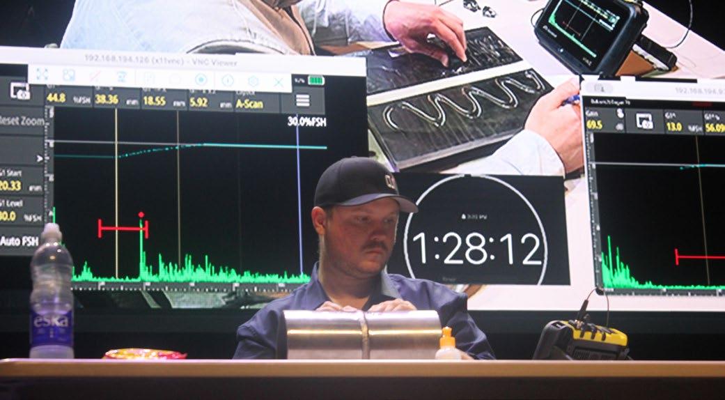
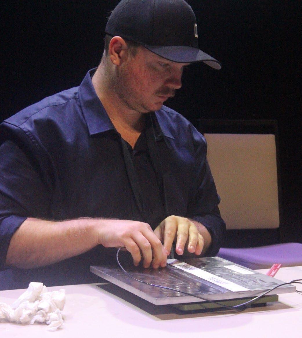
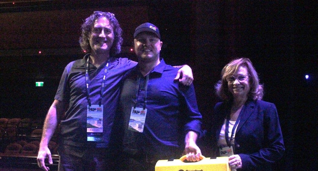
Understanding Radial Vibration Probes: Internal vs External Mounting
Monitoring machinery vibration is critical for maintaining performance, preventing damage, and ensuring operational safety.
BY SALAH ATTIA
Radial vibration probes play a central role in this process, providing real-time measurement of a shaft’s radial movement in two perpendicular directions, typically referred to as X and Y, or horizontal and vertical.
How They Work
A typical set-up involves two vibration probes positioned 90 degrees apart, either internally within the bearing or externally. This configuration enables accurate measurement of shaft vibration in both axes, supporting detailed analysis through spectrum and fullspectrum views, orbit and polar plots, bode and cascade plots, and shaft centreline tracking.
Both probes form part of a machine protection system. In standard configurations, the probe to the right of the counter-clockwise rotation (viewed from the drive side) is horizontal, while the second is vertical. Alternative orientations can be applied depending on the machine design and application requirements.
Internal Mounting: Precision with Limitations
Internal probe mounting is generally regarded as the most cost-effective method. It requires less machining, offers improved access to the shaft surface, and provides more precise bearing-relative data. This precision makes it particularly valuable for critical equipment where small variations in vibration can indicate emerging issues.
However, internal mounting also has its drawbacks. Accessing the probes for maintenance can be challenging, especially in the event of a fault. Cable routing requires careful planning to secure them and prevent damage, and there must be appropriate exit points for the cables. Additionally, precautions are needed to avoid oil leakage from the bearing housing.
External Mounting: Flexibility and Accessibility
External mounting allows probes to be replaced or adjusted while the machine remains in operation.
This is a major advantage in plants where downtime is costly. Eddy probes in external setups often have a favourable viewing area, and adjusting probe gaps is straightforward.
The trade-off is reduced precision in bearing-relative measurements compared to internal mounting. External installations may require more extensive machining, and longer probe or stinger lengths can introduce resonance effects. In steam turbines, thermal expansion can also influence accuracy.
Choosing the Right Approach
The decision between internal and external mounting depends on balancing precision requirements, maintenance accessibility, and operational constraints. For applications where accuracy is paramount and downtime for maintenance is acceptable, internal mounting may be preferred.
Where continuous operation and easy access are priorities, external mounting offers clear advantages. Regardless of installation method, radial vibration probes are indispensable tools in machinery condition monitoring, enabling early detection of faults, improving reliability, and extending equipment life.
Salah Attia

Technical Director at MCS, introducing a range of services to our customers, including vibration and oil analysis, thermal imaging, alignment, balancing and training (VCAT4, TCAT3, MLA2, CMRP, NER, RPEQ, MIEAust)
Email: salah attia@mcsturbo com
Phone: 0499881294
www mcsturbo com
www mdiaustralia com
Machinery Consultation and Services Pty Ltd -
Tech Note 1
Radial Vibration Probe
Two vibration probes (X&Y), 90 deg apart
Could be installed internally inside the bearing or externally.
Used to measure shaft radial vibration in two directions (X&Y) or (horizontal & vertical).
Viewing ( spectrum, full-spectrum, orbit plot, polar plots, bode plot, cascade plot, and shaft center line).
Both sensors are used as a part of the machine protection system
The first sensor on the right from the CCW rotation from the machine drive side is horizontal, and the second sensor is vertical. Different sensor orientations can be used.
Advantages of Internal Mounting:
1. Regarded as the most cost-effective installation.
2. Requires less machining work and is easier to implement.
3. Provides more precise bearing relative data.
4 Offers improved access to the shaft surface
Disadvantages of Internal Mounting:
1. Difficult to access machine probes in case of faults.
2. Cables need to be securely tied.
3 Exit points for the sensor ' s cable must be established
4. Precautions are necessary to prevent oil leakage.
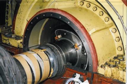
Advantages of External Mounting
1. Replacing probes can be done while the machine is in operation.
2. The Eddy Probe typically offers a favorable viewing area.
3. Adjusting probe gaps is easily done while the machine is running
Disadvantages of External/Internal Mounting
1. Bearing relative data is less precise.
2. Additional machining is necessary.
3. Longer Probe/Stinger length may lead to resonance.
4 Susceptible to thermal expansion, particularly in steam turbines
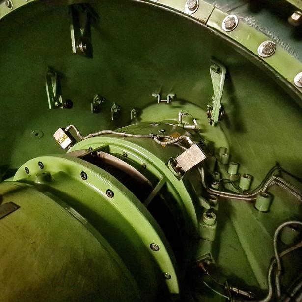
CIVA Confirmation of Frequency Dependence of TOFD Lateral Wave
Pulse-duration (ring-time) of the TOFD (Time of Flight Diffraction) lateral wave has been assumed to be based on the nominal frequency of the probe.
ED GINZEL1
1 UNIVERSITY OF WATERLOO, WATERLOO, ONTARIO, CANADA E-MAIL: EGINZEL@MRI.ON.CA
With the improved damping used for TOFD applications, these probes now have had their ring-time reduced to about 1.5 cycles. As a result of the short pulse duration, the bandwidth of these probes is greatly increased. However, assumptions based on the nominal frequency are only approximations. Underlying physics of beam divergence exacerbate these assumptions when considering the frequency content of the lateral wave. CIVA simulations are used to illustrate how using the nominal probe frequency underestimates the actual dead zone extent of the lateral wave.
Keywords: TOFD, lateral wave, CIVA, pulse duration
Introduction
In a recent paper [1], the geometric approximations used by Silk [2] and incorporated in standards [3, 4, 5] were shown to break down when the assumption that the ultrasonic energy enters and leaves the specimen at fixed points under the probes, cannot be held to a relatively small variation. Equations found in those standards can be reasonable approximations when the probe aperture is relatively small (e.g., 3-6mm diameter).
Although not codified, another assumption made in recent times has been to use 1.5 times the pulseduration of the nominal frequency of the probe to calculate the dead zones associated with TOFD. This seems to have come from a statement by Charlesworth [6] that although the earliest iterations of TOFD equipment used narrow bandwidth probes, it was not until TOFD probes began to be made using heavily damped elements, such that the pulse was reduced to 1.5 cycles, did the resolution by TOFD get improved.
Using 1.5 times the nominal frequency as the pulseduration of TOFD probes is perhaps convenient; however, it is not necessarily accurate. The primary source of probe damping is the metal-powder-loaded epoxy used as backing to the piezo-element. Other factors can also be a part of the damping, such as the applied voltage shape and subtle loading effects that can be had by front-loading with pressure variations from such things as how tightly the probe is secured to the refracting wedge or the pressure that the operator applies to the probe during scanning.
Perhaps the most significant deviation from the assumed wavelength being based on the nominal frequency is where in the beam profile the pulse is measured. It is well known that the rate a beam diverges is dependent on the probe frequency (or wavelength) and aperture. Divergence is inversely proportional to frequency and aperture as illustrated in Figure 1.
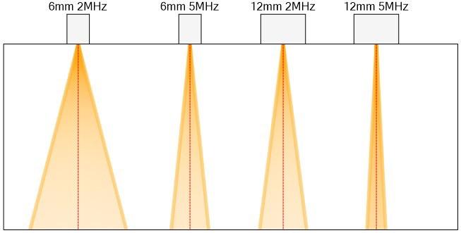
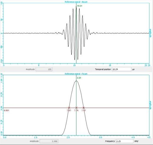
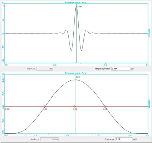
This representation is somewhat deceiving as it is based on continuous wave excitation at a single frequency or wavelength. Probes used in most industrial applications are operated in pulses rather than continuous excitation. When we look at the frequency content of the impulse shape of a probe it can be seen to contain more than one frequency. The shorter the pulse- duration the broader the frequency content. Figure 2 illustrates a 2.25MHz pulse with 9 cycles (left) and 1.5 cycles (right). The -6dB frequency content of the 9 cycle pulse ranges from 2.02MHz to 2.47MHz whilst the 1.5 cycle pulse ranges from 1.29MHz to 3.21MHz. This is the difference between a 20% bandwidth and 85% bandwidth.
Figure 1. Beam spread variations with aperture and frequency
Figure 2 Effect of pulse-duration on frequency content
With a well-made TOFD probe, designed to ring with just 1.5 cycles, the pulse will therefore contain a wide range of frequencies. And since beam spread is a function of frequency, the lower frequency content will spread more than the higher frequency content.
Confirming Frequency Drop using CIVA
A simple through-transmission model was made using CIVA simulation software to illustrate the reduction of frequency as we move off axis of the centre of the beam. A nominal 5MHz 6mm diameter probe with 85% bandwidth was configured as a transmitter and a smaller 2mm diameter probe as a receiver. These were placed in contact on a semi-circular block of steel with a 50mm radius. The receiver probe was initially positioned directly opposite the transmitter and then moved in approximately 5° increments away from the beam axis. Probe positions and associated FFTs are seen in Figure 3.
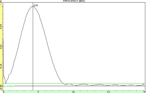
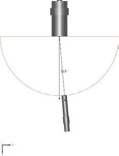
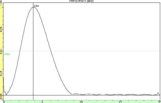
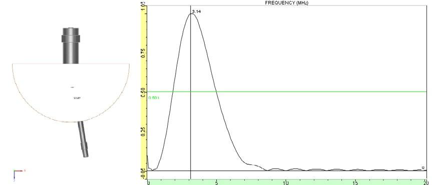

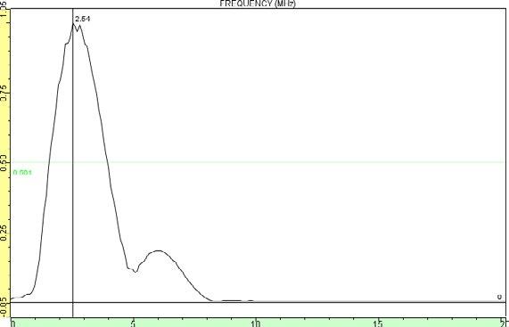
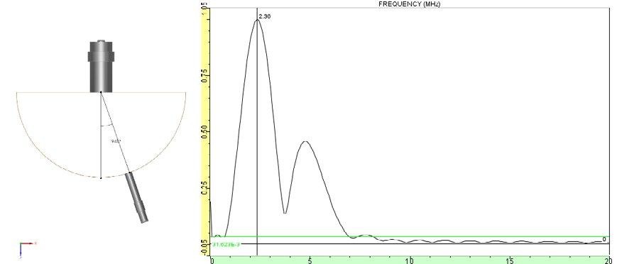
It is worth noting that even though the transmitter transducer is configured to pulse with a nominal 5MHz pulse, the received pulse at 0° offset from the beam axis has a slight downshift in frequency from 5MHz to 4.25MHz.
CIVA Evaluation of TOFD Lateral Wave Frequency
Having confirmed that the nominal frequency of the probe is not maintained when assessing the pulse offaxis of the centre beam, several TOFD configurations were made in CIVA and the frequency of the lateral wave measured.
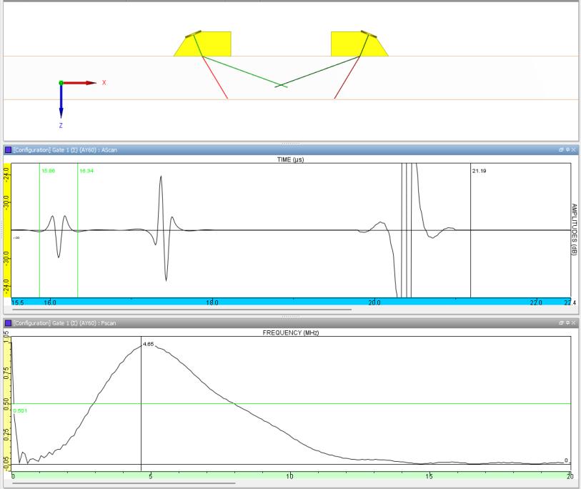
Figure 4 10MHz probe has a lateral wave downshift to 4.65MHz
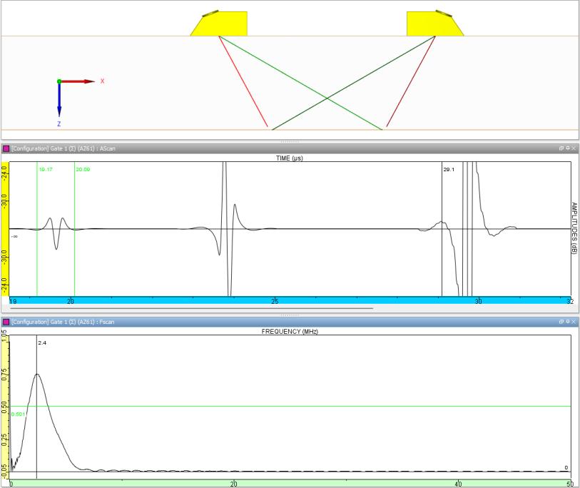
Figure 5 5MHz probe has a lateral wave downshift to 2.4MHz
Figure 4 illustrates a 10MHz probe with 85% bandwidth on a 70° refracting wedge. Used on a 15mm thick steel plate the 55mm PCS provides a 66% crossing point. The downshift in frequency is significant as the lateral wave is seen to be at 4.65MHz.
Figure 5 shows the simulation of 5MHz probe with 85% bandwidth on a 60° refracting wedge. When placed on a 33mm thick steel plate, the 76mm PCS provides a 66% crossing point.
Figure 3 Frequency downshift with offset from centre of beam
Again, the downshift in frequency is significant as the lateral wave is seen to be at 2.4MHz.
Confirmation of Lateral Wave Frequency Downshift
To confirm that significant downshift also occurs on a real test piece, a pair of TOFD probes 6mm diameter 2.25MHz were placed on a 33mm carbon steel block 33mm thick using 60° refracting wedges. Using Beamtool [7], Figure 6 shows how this provides a nearly direct path to the receiver for the mode-converted compression mode off the shear mode that has reflected from the backwall.
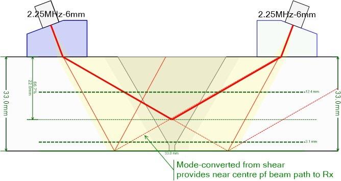
Having passed through slightly more than 20mm of polystyrene (Rexolite) the nominal 2.25MHz is already slightly downshifted, as polymers tend to preferentially allow lower frequencies to pass. When the signals are analysed in the frequency domain it is apparent that even at 2.25MHz there is a downshift in frequency content of the lateral wave relative to the nominal frequency. Figure 7 indicates the lateral wave having a centre frequency of 1.37MHz and when compared to the mode-converted signal which has less offset from the beam centreline, the downshift is very slight at 1.95MHz. (Note; amplitude of the modeconverted signal was decreased so as to avoid signal saturation).
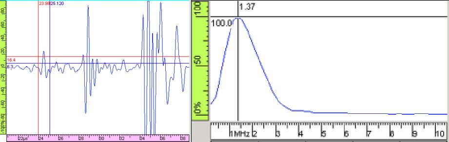
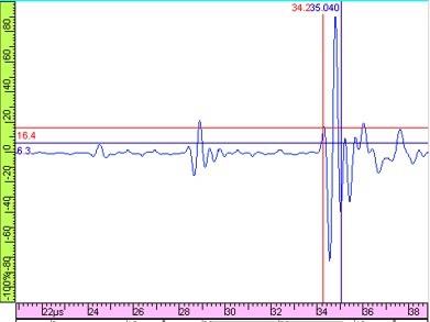
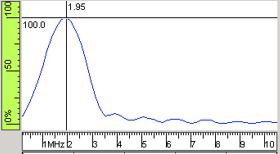
To some extent, the effective lateral-wave dead zone is a qualitative judgement. The probe used may not be a perfect 85% bandwidth and surface conditions of the part inspected may deteriorate the signal quality. Figure 8 illustrates a scan of a single V weld 25mm thick scanned using a 6mm diameter 10MHz probe on a 60° wedge.
Assessing the lateral wave centre frequency, it is indicated as being 4.5MHz instead of 10MHz (similar to the downshift predicted in Figure 4).
At 10MHz and at 1.5cycles, the lateral wave dead zone is estimated to be 5.0mm. At 4.5MHz the equation estimates a dead zone of 7.6mm. With the lateral wave straightened and the zero- depth determined using the maximum positive peak, the qualitative estimate of the dead zone is approximately 7.1mm. Even then, the straightened lateral wave has some slight movement in time resulting in a non-uniform depth of dead zone.
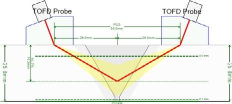

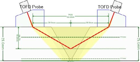

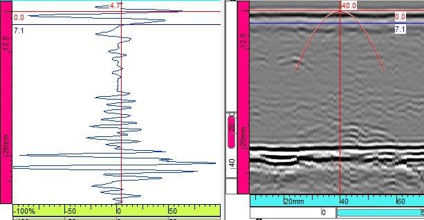
Conclusions
Estimation of the lateral-wave dead zone, by using the pulse-duration of the nominal probe frequency, is simply a convenient approximation. Using the assumed 1.5 cycles of the nominal frequency to estimate the dead zone is likely to underestimate the actual dead zone.
Due to the natural downshift of frequency content by moving off the centre axis of a beam, the lateral wave will always have a longer duration than the value calculated from the nominal probe frequency.
Pulse duration is one of the variables found in three separate equations in the TOFD standards. In addition to the lateral wave calculation, it is a factor in flaw spatial resolution and backwall dead zone calculations. And since the flaw spatial resolution and backwall calculations are made at positions with less offset from the beam centreline, the downshift of frequency will be less than experienced at the lateral wave.
Mode-converted reflection
Lateral wave
Figure 6. 2.25MHz probe setup on steel plate
Figure 7. Frequency analysis of 2.25MHz probe in setup from Figure 6
Figure 8. Dead zones for 10MHz 60° TOFD scan of weld in 25mm thick steel plate
Acknowledgements
We would like to thank Extende for their ongoing support with CIVA.
References
1. Ginzel, E., CIVA as an Aid to Understanding TOFD Ded Zones, www.ndt.net/article/ndtnet/papers/CIVA_ as_an_aid_to_understanding_TOFD_ dead_zones. pdf
2. Silk, Maurice, " The potential of scattered or diffracted ultrasound in the determination of crack depth", Research techniques in NDT, vol 3, June 1975
3. BS-7706-Guide to calibration and setting-up of the ultrasonic time of flight diffraction (TOFD) technique for the detection, location and sizing of flaws (withdrawn 2009)
4. EN-583-6- Non-destructive testing. Ultrasonic examination - Time-of-flight diffraction technique as a method for detection and sizing of discontinuities (withdrawn 2014)
5. ISO 15828 Non-destructive testing — Ultrasonic testing — Time-of-flight diffraction technique as a method for detection and sizing of discontinuities
6. Charlesworth, J.P., Temple, J.A.G., Engineering Applications of Ultrasonic Time-of- Flight Diffraction, Second Edition, Research Studies Press LTD, 2001
7. Beamtool Software, www.eclipsescientific.com/beamtool.html

NDT World Event Calendar
15th International Workshop on Structural Health Monitoring (IWSHM)
9 to 11 September | California, United States
The biennial workshop aims to assess the current state-of-the-art technologies and to identify key breakthroughs and emerging R&D challenges that are critical to structural health monitoring. The rapid growth in AI-related technologies and increasing demands for safety and sustainability have driven industries toward greater autonomy and mobility, with focus on renewable energy and efficiency. These trends will lead to greater demands on structural health conditions to ensure safety and autonomy.
For further information, visit: iwshm2025.stanford.edu/
ASNT 2025: The Annual Conference
6 to 9 October | Florida, United States 'Access Granted' is more than just a theme—it's your key to the future of NDT. Join industry leaders as we explore innovations, share insights, and open doors to the latest advancements in NDT. This must-attend event provides unparalleled networking, hands-on technology showcases, and an immersive experience designed to expand your knowledge and elevate your career. Hosted by the American Society for Non-destructive Testing, ASNT 2025 will be held at Disney's Coronado Springs Resort, with over 100 technical sessions, 210 exhibitors and 2,200 attendees.
For further information, visit: asnt.eventsair.com/asnt-2025
55th NDE for Safety 2025
11 to 13 November | Litomysl, Czech Republic
Theconference will cover all aspects of non-destructive testing (NDT) and evaluation (NDE) of materials and structures across a broad range of technical fields. Hosted by the Czech Society for NDT, the event provides a unique opportunity to bring together researchers, practitioners, and experts involved in the development, application, and standardisation of NDT/NDE methods. Manufacturers and service providers are also invited to showcase their latest products, technologies, and innovations.
For further information, visit: www.cndt.cz/en/conference
The 17th Asia Pacific Conference for Non-Destructive Testing (APCNDT)
11 to 14 May 2026 | Hawaii, USA
APCNDT is set to be an unmissable event for NDT professionals across the globe. Held under the theme Breaking Barriers: NDT Solutions for a Changing World – Innovate, Adapt, Transform, this premier conference will showcase the latest innovations and emerging technologies that are redefining non-destructive testing. Attendees will have the opportunity to connect with global experts, share knowledge, and explore new solutions to address the evolving challenges faced by industries worldwide. Join us to discover how NDT is driving transformation, and paving the way for a dynamic future.
For further information, visit: www.apcndt2026.com
The 14th European Conference on Non-Destructive Testing (ECNDT 2026)
15 to 19 June 2026 | Verona, Italy
ECNDT 2026 is a leading international event hosted by the European Federation for Non-Destructive Testing. Bringing together experts, researchers, and professionals, the conference is a hub for sharing innovation, research, and emerging technologies shaping the future of inspection and quality assurance. The program features technical presentations and case studies across a range of sectors, complemented by a dynamic exhibition. This connection between research and practical application encourages collaboration, networking, and advancement of NDT worldwide.
For further information, visit: www.ecndt2026.org
Alliance Solutions Group
Alliance Solutions Group (ASG) is your trusted partner in advanced Non-Destructive Testing equipment. They specialise in providing innovative inspection solution packages tailored to meet the needs of industries that require accurate, reliable and repeatable inspection results.
ASG’s approach is designed to offer:
• Comprehensive Solutions: Providing support that covers every aspect of your inspection needs.
• State-of-the-Art Equipment: Benefit from the latest technology that provides accurate and reliable results.

Fujifilm DynamIx HR2 Computed Radiography
If you are looking to modernise and improve your radiographic testing operation, upgrading to Computed Radiography (CR) is your answer. The process involves swapping your old film, processor and chemicals for a flexible imaging plate and Fujifilm HR2 CR scanner and computer. CR will produce higher resolution images with superior contrast, making it easier to identify smaller defects and other anomalies faster than processing conventional X-ray film.
If you are looking to improve the sustainability and environmental friendliness of your operation, upgrading to CR will also tick this box. You will no longer need
By choosing ASG, you're not just getting equipment, you're gaining a partner committed to your operational excellence. ASG’s solutions will enhance safety and increase productivity.
ASG is here to support your inspection requirements. Here’s how you can get started:
• Contact ASG: Talk to ASG and discuss the best solutions for your needs.
• Explore ASG Packages: Select an inspection package that aligns with your inspection campaign requirements.
• Leverage ASG Expertise: Utilise their experience to maximise your investment.
For more information, visit: asgndtsupplies.com
to buy X-ray film, processing chemicals and other consumables. Similarly, you won’t have any spent chemicals to dispose of.
By replacing film with digital files, you no longer need to worry about storing and archiving film. Faded and deteriorated exposures also become a thing of the past. Retrieving and sharing images also becomes a much simpler exercise.
There is an initial capital outlay, but the investment can easily repay itself with virtually no ongoing costs. Faster workflows, the convenience of not needing to regularly order consumables, being available to work at any time and the benefits of dealing with digital files all support the case for upgrading to CR.
For further information, visit: www.axt.com.au/HR2
International Tube Testing
Active in the NDT industry since 1978, Charlie Panos has over 40 years of experience. He provides International Tube Testing (ITT) was established by Charlie Panos in 2000. With over 40 years of industry experience, Charlie has in-depth expertise and qualifications in the engineering, testing and inspection industry.
ITT was formed to fill a growing need for accurate, dependable specialised engineering testing services. ITT provides specialised IRIS and RFT tube testing and has tested almost every boiler design in the process,
petrochemical and power industries in Australia, the Pacific Islands, Papua New Guinea, Indonesia, Malaysia, Philippines and India.
The company can test tube sizes from 16mm up to 200mm, including straight tubes and tubes with bends for industries as diverse as pulp and paper, fabrication, maritime and aerospace.
ITT prides itself on delivering personalised, ethical service every time and has the field proven experience, technology and determination to ensure all your requirements are exceeded.
For further information, visit: tubetesting.com.au

Laboratory for Materials Advanced Testing Services (LMATS)
If you are looking to modernise and improve your LMATS (Laboratory for Materials Advanced Testing Services) is a leading Australian provider of non-destructive testing (NDT), advanced inspection, and engineering consulting services. With a national footprint and over two decades of experience, LMATS supports critical industries including infrastructure, mining, energy, defence, transport, and manufacturing.
The company specialises in a broad range of NATAaccredited and ISO-certified services, including ultrasonic testing (UT), radiographic testing (RT), magnetic particle and dye penetrant inspection, phased array UT(PAUT), time of flight diffraction (ToFD),

Russell Fraser Sales: Supplying PAUT for Over 30 Years
For over 25 years, Russell Fraser Sales (RFS) has been a trusted name in NDT across Australia and the Asia-Pacific region. Founded on a commitment to technical excellence and customer support, RFS has supplied inspection professionals with high-quality equipment from the world’s leading brands.
From ultrasonic testing and magnetic particle inspection to visual inspection and eddy current testing, RFS has built a reputation for delivering reliable solutions backed by expert advice and service.
In 2024, Russell Fraser Sales entered a new chapter by joining the Cebeco Group, a move that enhances its reach and resources while maintaining its specialist focus on NDT. This partnership strengthens RFS’s ability
Woods
With 35,000 professionals across 60 countries, Wood PLC is one of the world's leading consulting and engineering companies operating across Energy and Resources markets.
Here in Australia, the broad range of services Wood offers its clients includes machinery vibration and lubrication analysis for all types of equipment, across all industries. Their certified personnel can provide endto-end routine measurement, analysis, and reporting; alternatively, Wood can supplement your people to match your needs.
Wood is vendor-agnostic and works with a wide range of wireless, wired, and portable hardware and software platforms to provide routine and troubleshooting services to the very highest level.
The company does not stop at simply finding and diagnosing problems. From skid to piping to vessel,
guided wave testing, positive material identification (PMI),coating inspections, and drone testing. Their in-house laboratories also offer mechanical testing, chemical analysis, metallurgical evaluation, and failure investigations.
What sets LMATS apart is their technical expertise, fast response, and innovative approach. Their highly skilled team of engineers and technicians partner closely with clients to deliver accurate, reliable, and timely results, no matter how complex the challenge.
With facilities in Melbourne, Perth, Sydney, Brisbane, and regional locations, LMATS is trusted by clients nationwide to ensure asset integrity, compliance, and operational safety.
For further information, visit: lmats.com.au
to support customers nationwide with faster access to products, training, and technical support.
Among RFS’s standout offerings is the Sonatest Veo3a cutting-edge Phased Array Ultrasonic Testing (PAUT) instrument. Designed for advanced inspections, the Veo3 features a high-resolution multi-touch display, intuitive user interface, and powerful onboard processing. It supports full matrix capture (FMC) and total focusing method (TFM), making it ideal for complex flaw detection and imaging. Its rugged, IP65-rated construction ensures it performs reliably in demanding field environments.
With a strong legacy and a future backed by Cebeco, Russell Fraser Sales remains dedicated to delivering the tools and expertise professionals need to inspect with confidence.
For further information, visit: rfsales.com.au
Wood has an unrivalled track record of engineering actionable solutions. They also offer machinery alignment and balancing, optical motion amplification, thermography, bearing failure analysis, root cause analysis facilitation, FEAs, flow analysis, noise studies and much more.
Plus, they practice what they teach. Wood offers vibration and lubrication analysis training per ISO 18436 Parts 1 to 4, with optional AINDT certification. Their public courses are delivered in Perth and Brisbane by active principal practitioners with decades of experience. Wood can also provide bespoke courses at your site or venue.
Wood currently offers LCAT1, VCAT1 and VCAT2 training, and will be expanding their catalogue soon. The LCAT I and VCAT I courses each provide three days of training, plus a two hour certification examination. The VCAT2 duration is four days of training, plus a three-hour certification examination.
For further information, visit: vdn.woodplc.com

Smartchem Industries
Smartchem Industries is your trusted partner for magnetic particle and dye penetrant requirements, with over 100 years’ combined experience in the manufacture and distribution of magnetic particle and dye penetrant consumables.
Smartchem is 100% Australian owned and proudly manufactures in Australia with Australian resources where possible. Smartchem prides itself on service, both technical and in the delivery of their products.
The Smartcheck MPI range complies with the requirements ISO-9934.2 and other relevant standards. The Smartcheck dye penetrant range has been third party type tested to ISO 3452.2 by MPA Hanover in Germany, including Smartcheck Dye Pen Fluoro—a level
3 water washable/solvent removable fluorescent dye penetrant. All CoC and SDS are available on the website which is a useful reference tool for an audit or where a copy is required in the field.
SmartChem is the exclusive distributor for the Matcon range of magnets and equipment. They are also exclusive distributors for Promag UV lights and equipment.
SmartChem supplies direct and has a comprehensive network of resellers. Heatleys Safety and Industrial (heatleys.com.au) are their exclusive distributor in Western Australia, while Accurate Instruments (accurate. kiwi) cover both the North and South islands in New Zealand. For distributors on the east coast of Australia, contact Smartchem direct.
Quality products and service at a reasonable price, that’s the Smartchem difference.
For further information, visit: smartchem.com.au
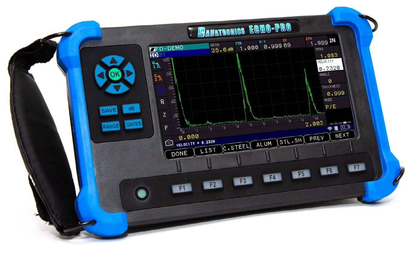


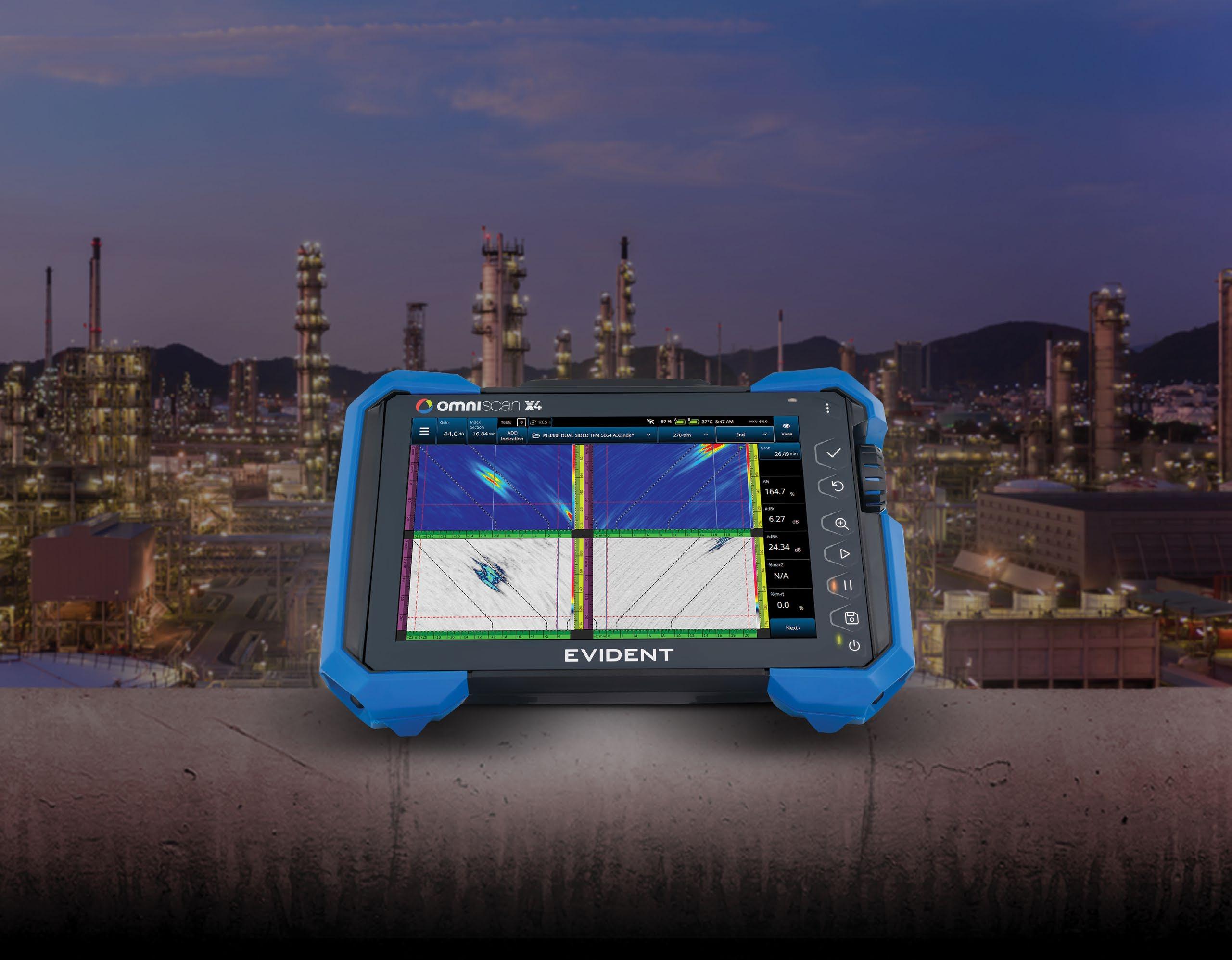
Be Ready for What’s Next
The New OmniScan™ X4 Flaw Detector
Engineered for Speed & Simplicity
Advanced imaging technology and an easy-to-use interface allow users of all skill levels to perform fast, accurate inspections—boosting performance and streamlining workflows.
Proven to Perform, Trusted to Deliver
An all-in-one imaging platform, coupled with unmatched portability and versatility, delivers exceptional results in even the most challenging inspection environments.
Designed to Evolve with Your Needs
With free quarterly software updates, the OmniScan X4 empowers you to continuously adapt to future inspection needs—ensuring that you’re always ready for what’s next.