
Version 1.1
Published 2023 by
Waugh Thistleton Architects
35 Pitfield Street
London, N1 6HB
DISCLAIMER
The New Model Building is a set of design principles that demonstrates a methodology for building mid-rise residential properties using a low-carbon engineered timber structure. This has been prepared for Build by Nature in collaboration with other professionals including structural engineers and fire specialists. All involved have exercised reasonable skill and care to develop a methodology that performs to the relevant standards, UK Building Regulations and NHBC technical standards current at the time of writing, if correctly implemented.
These details and supporting information are provided on an ‘as is’, ‘with all faults’ basis, and no warranties, guarantees, conditions or other terms are given or implied.
This study was prepared for Built by Nature and is not to be relied upon by any third party. The use of this methodology and information does not relieve any consultant of their responsibility to ensure the suitability, performance, compliance and robustness of their designs and we expressly exclude liability to any party for any loss or damage (whether direct or indirect, and whether or not foreseeable) arising from the use of the following information.
THE NEW MODEL BUILDING
The New Model Building is a set of design principles that showcase an exemplar methodology for building residential developments in a climate emergency.
Complying with current and consulted UK statutory guidance, The New Model Building utilises a low carbon engineered timber structure coupled with a non-combustible façade, demonstrating a way of building that responds to the challenge of meeting net zero carbon.
THE TEAM
Waugh Thistleton Architects is a London based architecture practice with an international reputation for thought leadership in the use of sustainable materials. We create award winning buildings which minimise their environmental impact whilst achieving the highest architectural standards. We believe passionately that sustainability and world class design are one and the same thing and strive to produce innovative and imaginative solutions that harness leading technologies. We are known around the world for the design of our buildings, our commitment to the use of offsite construction and our pioneering work in environmentally viable architecture.
The New Model Building is the result of a collaboration with the following industry experts:

And has been peer reviewed by:


WHY WE NEED THE NEW MODEL BUILDING
Although the UK leads the world in building with engineered timber, with over 500 completed buildings, recent changes to Part B of the Building Regulations have resulted in a lack of confidence in how engineered timber can be used for multistorey residential building.
While the change in legislation was not prescriptive or intended to prejudice any one material, it has had an inadvertent and discriminatory effect on the use of engineered timber - our only viable low embodied carbon structural material - at a time when the need to reduce carbon emissions has never been more urgent.
WHAT IS THE NEW MODEL BUILDING?
The New Model Building (NMB) is an exemplar methodology for building residential developments in a climate emergency. Fully compliant with UK statutory guidance, it utilises an encapsulated low carbon engineered timber structure coupled with a non-combustible façade system, demonstrating a way of building that responds to the challenge of meeting net zero carbon while fully complying with Part B of Building Regulations 2022 Amendments. The New Model Building arrives at a pre-assessed design philosophy for mass timber housing blocks of up to six storeys
Developed in collaboration with structural engineers Buro Happold and UCL’s fire engineering experts The New Model Building is a set of standard details and performance specifications which have been pre-assessed by the National House Building Council (NHBC) to facilitate developers obtaining Buildmark, NHBC’s warranty and insurance cover for new-build homes.
FLEXIBLE PRINCIPLES TO APPLY TO YOUR PROJECT
We used a typical building to demonstrate how the principles and details can be used and applied. However The New Model Building Principles and Typical Details are not prescriptive and can be applied to deliver projects of varying forms and sizes, to produce bespoke designs for each site.
MASS TIMBER ELEMENTS
The mass timber elements that can be used to deliver a New Model Building are glulam columns and beams, LVL columns and beams and CLT walls and floor slabs. These can be used in combination with other traditional elements to deliver buildings that meet site requirements.
ROOF
Timber roof structure, installed to minimum 1:40 falls with BROOF(t4) certified roof build-up
STRUCTURE
Fully encapsulated, low embodied carbon, engineered timber structure
FAÇADE
Class A2-s1, D0 external wall system, designed in accordance with Part B Regulation 7
PENETRATIONS
Penetrations through structure protected using compliant penetration details
BALCONIES
Non-combustible steel balconies, designed in accordance with MHCLG guidance documents
WATERPROOFING
Best practice methods for prevention and mitigation of moisture ingress
NEW MODEL BUILDING DESIGN PARAMETERS
The New Model Building is a methodology for delivering residential projects within the following parameters
BUILDING HEIGHT
<18m
FLOOR TO FLOOR
2925 mm
FIRE COMPARTMENT
REI 60 and K2 60
SPRINKLERS
Automatic sprinkler system
UPFRONT EMBODIED CARBON (A1-A5)
326 kgCO2e/m2 (excluding sequestration)
EMBODIED CARBON (A-C)
271 kgCO2e/m2 (RIBA 2030 Built Target)

BUILDING REGULATIONS
Complies with all current Approved Documents
EWS1 FORM
No combustible materials are used in the external walls
Allowing the buildings to achieve an EWS1 Form and meet GLA funding requirements
NHBC LETTER OF COMFORT
A pre-assessed design philosophy
Cradle-to-Practical Competition (Modules A1-A5)
Cradle-to-Grave (Modules A1-A5, B* & C) - used for GLA WLC reporting
Cradle-to-Grave (Modules A1-A5, B* & C) - including sequestered carbon storage
*B2&B3basedonGLAWLCguidanceB6&B7notincluded
Calculating the Lifecycle Embodied Carbon A-C allows the carbon sequestration of the timber structure to be offset against the building
Sequestered carbon (Life Cycle Embodied Carbon A, B1-5, C)
Non structural items
Superstructure - Engineereed timber Superstructure - Concrete
NEW MODEL BUILDING KEY BENEFITS
Whilst the primary driver for The New Model Building is the carbon impact, the methodology offers other delivery and efficiency benefits:
KEY BENEFITS
DESIGN COMPLIANCE
The New Model Building comprises a set of details, of key junctions. These details are fully compliant with UK Building Regulations and will facilitate production of the technical design. They have been developed in liaison with national warrantee provider NHBC to expedite the technical approval process.
75% CARBON SAVING
Using an archetype residential building of six stories and 29 flats we completed a whole life carbon assessment (A-C) using material volumes from the BIM Model and manufacturer Environmental Product Declarations (EPDs) and compared this to an equivalent building built using traditional methods (ie concrete and steel frame).
The archetype New Model Building achieves an A+ LETI rating, and a 74% reduction when compared to the equivalent concrete and steel building.
COST COMPARATIVE
Comparing the Archytype New Model Building with an equivalent reinforced concrete frame building using data from Q1 2023 showed that there was a 5% capital uplift to deliver The New Model Building. This figure does not include cost savings achieved through having a reduced programme, or on site preliminary cost benefits.
QUICKER TO BUILD
Mass timber frames are typically erected in a third of the time of a traditional insitu concrete frame.

SAFER AND QUIETER CONSTRUCTION
Fixing into timber requires handheld electrical tools speeding up construction and is significantly quieter.
FEWER DELIVERIES
60% fewer deliveries are required to construct an engineered timber frame, reducing in less noise, disruption and pollution to site neighbours.
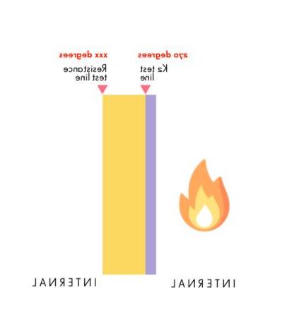
K2 TEST LINE RESISTANCE TEST LINE
K2 test line Resistance test line

Timber protected by K2 lining. This gives higher through wall performance than a standard REI test for the same duration, as it tests to the face of the timber and not the other side of the wall.
INTERNAL INTERNAL/EXTERNAL
BS EN 13501 - 2 K2 or REI
Non-combustible façade CORE FLAT FLAT FLAT FLAT FLAT COMPARTMENTATION
Engineered timber structure
Encapsulation
60 minute fire compartment
Protected core with escape stair
Engineered timber structure
Encapsulation
PENETRATIONS
Engineered timber structure
Fire stopping product
FIRE STRATEGY PRINCIPLES
The New Model Building is fully compliant with all current building regulations, including Part B Regulation 7. The pages below use key principles to demonstrate how specific building elements adhere to these standards. The principles are guidelines on best practice.
FAÇADE DESIGN
The methodology utilises a non-combustible façade system constructed from materials as defined in Approved Document Part B, Regulation 7. Example materials that could be applied include non-combustible rainscreen cladding materials such as brick, clay tiles, A1 rated carrier systems, boards and insulation materials, light gauge steel framing systems and proprietary steel and aluminium fixings.
ENCAPSULATION
The structural design has been developed in accordance with STA Structural timber buildings fire safety in use guidance –Volume 6 – Mass Timber Structures. All timber elements are fully encapsulated with gypsum board applied in accordance with K-class test certifications with a max temperature of 200 degrees. Using this method the timber structure is fully protected and will not be affected by fire.
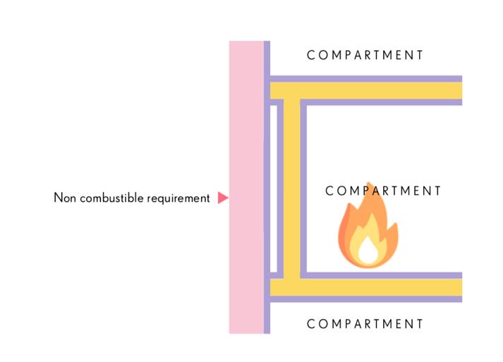
COMPARTMENTATION
The fire compartments are 60 minutes REI fire rated to following guidance in AD Part B - Table B4. Residential 1a - Block of Flats with sprinkler system - Up to 18m.
PENETRATIONS
Penetrations through the fire compartments are designed to be sealed and treated with the appropriate fire collars and sealants. These are carefully selected to ensure specification, procurement and installation is carried out in line with test certifications or evidence backed engineering judgements.
ROOF DESIGN
The specification of roof coverings are required to be in accordance with AD Part B and as designated by BS
9991:2015 Table 8 or equivalent European classification Broof T4.

945 degrees in 60 mins
Up to 945 degrees in 60 mins Up
K 2 6 0 – S T A m o d i f i e d Protection
Timber not involved in the fire
Max Temp on inside surface
200 degrees 70 degree safety factor included.
R E I 6 0 – C L T o n l y Demonstrates that CLT retains integrity, load bearing capacity and insulation to 60 mins
BS EN 13501 -2 TESTS
5 LEVELS OF FIRE PROTECTION
4 NHBC QUESTIONS
The New Model Building provides 5 key layers of fire protection. These combined deliver the basic principle to provide adequate detection and contain the fire in the unit of origin, giving the occupants the best chance to remain safe during a fire.
K 2 6 0 - S t a n d a r d Protection
Timber not involved in the fire
Max Temp on inside surface 270 degrees prevents pyrolysis
Up to 945 o in 60mins
K2 60 – STA modified Protection
K 2 6 0 – S T A m o d i f i e d Protection
Timber not involved in the fire
Timber not involved in the fire
Max Temp on inside surface 200 degrees 70 degree safety factor included.
Maximum temperature on inside surface 200o, 70o safety factor included.
Up to 945 o in 60mins
REI 60 – CLT only
R E I 6 0 – C L T o n l y
Demonstrates that CLT retains integrity, load bearing capacity and insulation to 60 mins
Demonstrates that CLT retains integrity, load bearing capacity and insulation to 60 mins
Lots of CLT manufacturers have done this test
Lots of CLT manufacturers have done this test
K2 60 STA modified + REI 60 for CLT only
K 2 6 0 S T A m o d i f i e d +
R E I 6 0 f o r C L T o n l y
Timber not involved in the fire
W h a t a b o u t q u a l i t y o f w o r k m a n s h i p ?
The system is described through details and sequencing diagrams if not installed correctly the liability lies with the installer not with NHBC. If plasterboard fails CLT still achieves REI 60. W h a t a b o u t S T A G u i d a n c e ? We will specify compliance with STA guidance – achieving 200 degrees on the face of the CLT behind the plasterboard
Every building using the NMB guidance will need their own fire engineer and fire strategy which will be assessed by NHBC on a case by case basis.
Timber not involved in the fire
Maximum temperature on inside surface 200o includes 70o safety factor
Max Temp on inside surface 200 degrees includes 70 degree safety factor
CLT retains REI integrity, load bearing capacity and insulation to 60 mins
R E I 9 0 – C L T w i t h b o a r d
Demonstrates that CLT with board retains integrity, load bearing capacity and insulation to 90 mins
I s i t m i x i n g a m a t c h i n g ?
The NMB does not include a Fire Safety Management and Emergency Plan. Each design team must create their own project specific plan.
CLT retains REI integrity, load bearing capacity and insulation to 60 mins
Both tests K2 and REI are described in BS EN13501-2 Belt and Braces approach to performance. CLT protected more than it would be with a CLT and plasterboard REI60 test
A fire safety management plan details the arrangements to implement, control, monitor and review fire safety standards and to ensure those standards are maintained under Article 11 of the Regulatory Reform (Fire Safety) Order 2005. It must be produced by the responsible person but should be fully aligned with the UCL Fire Report.
W h a t i f t h e f i r e s p r e a d s t h r o u g h s o c k e t s ?
REI test includes service hole penetrations in the test
STEEL BALCONIES GROUND FLOOR CONCRETE UPSTANDS
End grain sealer and DPC separates the timber from concrete upstand
SOLID CLT ROOF
All balconies are prefabricated steel either fixed to the CLT or independent steel structures
PRINCIPLES FOR WET AREAS
Minimum10degrees
Minimum1:5.5 10º
All elements of a CLT roof should be to a minimum fall of 1:5.5/10º
BATH/SHOWER ZONE
Area of CLT to be covered with robust waterproofing layer in wet areas
MOISTURE MANAGEMENT THROUGH DESIGN
The New Model Building design principles require designers to consider water and moisture management throughout the design, construction and in-use. Once timber products absorb water above the intended in-service moisture content, then loss of strength, dimensional changes and decay may occur. Consideration of how to minimise moisture damage can reduce the likelihood and severity of leaks and related damage.
Designers should pay careful attention to the detailing of areas at the highest risk of leaks and moisture damage, such as: roofs; ‘wet’ areas with active plumbing fixtures; areas in contact with the ground floor slab and connections and fixings.
DESIGN PRINCIPLES
Ground Floors
Where internal engineered timber, load-bearing walls or columns are in contact with the ground floor slab, the bottom of the timber must be at or above the internal finished floor level on a brick, block or concrete upstand. A DPC and end grain sealant must also be installed to prevent moisture from wicking into the timber.
Balconies
Where required, the New Model Building methodology uses prefabricated steel balconies, either fixed to the engineered timber structure or as independent steel structures. The design of these is not specific to the system and the designer should ensure compliance with all relevant standards and guidance.
Roofs
Solid CLT roof decks must be at a minimum roof angle of 10 degrees to minimise the risk of standing water. Other lightweight roof systems such as joisted roofs with plywood decks must allow for a minimum fall of 1:40 so water can run off. The design should therefore prevent an accumulation of standing water and the designer should consider ways to ensure the early detection of impact and progress of moisture should it occur.
Wet Areas
The design team should identify all areas in the building with active plumbing fixtures or appliances. Typically, these include bathrooms and kitchens. Protection and risk reduction strategies must be used in all identified wet areas. The floor can be substituted with a timber joisted floor locally throughout the wet area or two of the following four mitigation measures should be used:
– Tanking membrane
– System leak detection monitor
– Local leak detection system
– Ventilation Zones
– Preservative treatments
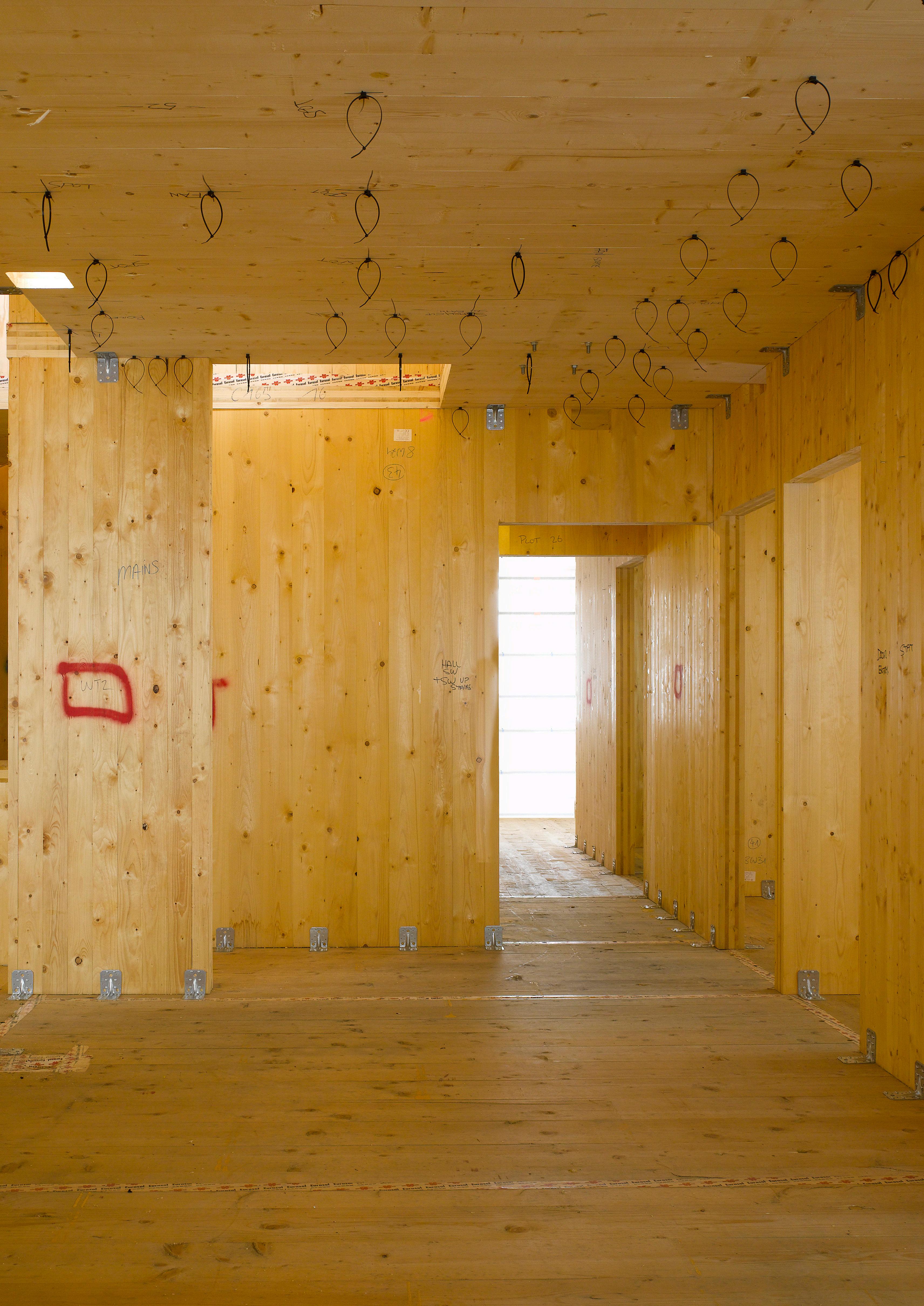
CLT when stored on site must be protected
The area of timber that has been affected should be measured ASSESS AFFECTED AREA
MOISTURE TESTING
Damp wood must not be enclosed. Timber must be tested before being enclosed or covered.
Surface lamella damage can be locally replaced with plywood LOCALISED REPLACEMENT
MOISTURE MANAGEMENT ON SITE
When designers/developers submit an application to NHBC using the New Model Building Philosophy they must incorporate a Risk Assessment and Method Statement (RAMS) as part of an on-site moisture management control plan (MMCP). The RAMS must outline the design, methods, and requirements for protecting the system from weather exposure and mechanical damage during storage, transportation and installation. The MMCP should be provided before construction for use during fabrication, delivery to site, erection and delivery phases. MMCPs must be project specific, and form part of the construction management plan submitted as part of any tender return. MMCPs must be developed in conjunction with the timber supplier and project engineer.
The MMCP must include practices such as:
– how to protect timber elements store on site
– drainage during construction
– end grain and joint taping protection
– how to dry timber elements
– how to remove surface water
– moisture content testing strategy prior to encapsulation
REMEDIATION STRATEGY
If engineered timber is found to have been exposed to moisture the affected area should be assessed to determine the extent of any damage and a suitable remediation strategy defined. The assessment should consider factors that affect the level of damage to the engineered timber, such as:
– total area of engineered timber exposed to moisture
– how long the engineered timber has been exposed to moisture
– depth of moisture exposure to the engineered timber elements – presence of mould or decay to the engineered timber – ability to dry the affected area, including factors such as site access, exposure, reliance on secondary contractors etc.
In many cases, allowing the timber to dry to a moisture content of <20% will be sufficient and the engineered timber will not need to be replaced, however, if the assessment recommends repair or replacement, this work should be carried out by a contractor familiar with the material. Methods for this will depend on the extent of the damage, but will typically include: rout and infill with locally supplied plywood or partial to full panel replacement.
NEW MODEL BUILDING TYPICAL DETAILS
The New Model Building principles have been used to create a suite of Typical Details to demonstrate how to construct critical junctions that comply with current and consulted UK statutory guidance.
The New Model Building Typical Details include:
– External wall details
– Internal wall details
– Window details
– Balcony connection details
– Roof details – Floor slab details
– Penetration details
– Typical fabric build ups
– Fire compartment details.
The sequencing of the installation is important to clarify how the fire and moisture proofing lines are maintained. In the Detail Guide - see note below - there are 4 sets of sequencing diagrams . The objective of these is to help designers and installers to understand how details should be put together and assist with the translation of drawn information to construction on site.
The sequencing diagrams on the left provide a step by step explanation of how to install a typical steel balcony connected to the CLT slab. The diagram illustrates how continuity of the fire barriers is maintained. This level of detail can help to reassure warranty providers and approved inspectors that these important interfaces are being carefully considered.
NMB SUITE OF DOCUMENTS
The new model building is described in 3 documents:
Guide
This document provides a high level overview of the New Model Building
Detail
The detail document is an easy to use guide that takes each group of details and highlights what designers and installers need to look out for when detailing and building the system. A helpful checklist accompanies each detail to draw attention to the important considerations. The details reference the performance specification which describes the requirements and standards that the materials need to achieve.
Evidence
In-depth information produced throughout the duration of this project which informed conversations with NHBC can be found in the Philosophy document, the Structural Design document produced by Buro Happold and UCLs Fire Strategy Document. These are collated within the Evidence document.
All three documents can be accessed on the BBN website via this QR Code.
If you would like to know more about the New Model Building please contact Waugh Thistleton Architects info@waughthistleton.com.

GUIDANCE DOCUMENTS
The following open source guidance documents are included in the Appendix for ease of reference. Users should ensure they refer to the current version of each document. Documents included are listed below:
GENERAL
- TRADA’s National Structural Timber Specification For Building Construction Version 2.0.
- TRADA Cross-laminated Timber Design and Performance
- SCI Technical Report ED017 Design and Installation of Light Steel External Wall Systems
FIRE
- STA Structural Timber Buildings Fire Safety In Use Guidance Volume 6 - Mass Timber Structures; Building Regulation compliance B3(1) STA fire safety and guidance project Version 2.1 May 2023
- STA 16 Steps to fire safety. Promoting good practice on construction sites. Version 4.3 October 2017
MOISTURE MANAGEMENT
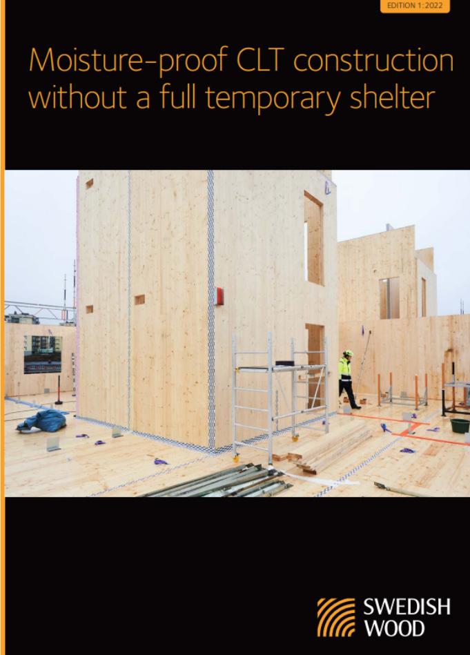
- Swedish Wood/TDUKs Moisture-proof CLT construction without a full temporary shelter Edition 1:2022
- STA Moisture Management Strategy, Process guidance for structural timber buildings, Version 1.0 July 2022
- STA Advice Note 14 - Robustness of CLT Structures - Part 1 - Key principles for moisture durability
- STA Technical Note 23 - Durability by design – mass timber structures – STA 2021
- STA Technical Note 24 - Moisture protection during construction
The New Model Building design principles comply with the following statutory documents and guidance :
– All Approved Documents, specifically AD Part B, Regulation 7
– Structural Timber Buildings Fire Safety in Use Guidance Volume 6 - Mass timber structures;
– Building Regulation compliance B3(1) STA Fire Safety Research and Guidance Project Version V1.1 (October 2020 )
– Structural Timber Association: 16 Steps to fire safety. 2017 – Onsite fire safety guidance
Further reference documents include:
Berners-Lee, M., 2010. What’s the carbon footprint of ... building a house. [Online] Available at: theguardian.com/ environment/green-living-blog/2010/oct/14/carbon-footprint-house [Accessed 20 May 2021].
Circular Ecology, 2019. Embodied Carbon - The ICE Database. [Online]
Available at: circularecology.com/embodied-carbon-footprint-database.html [Accessed 20 May 2021].
FCB Studios, 2021. FCBS Carbon. [Online]
Available at: fcbstudios.com/fcbscarbon [Accessed 20 May 2021].
GLA, 2020. Mayor of London’s Design for a Circular Economy Primer. [Online]
Available at: london.gov.uk/sites/default/files/design_for_a_circular_economy_primer_ggbd_web2.pdf [Accessed 20 May 2021].
LETI, 2020. LETI Climate Emergency Design Guide. [Online]
Available at: leti.london/cedg [Accessed 20 May 2021].
LETI, 2020. LETI Embodied Carbon Primer. [Online]
Available at: leti.london/ecp [Accessed 20 May 2021].
Office for National Statistics, 2021. Construction statistics, Great Britain: 2019. [Online]
Available at: ons.gov.uk/businessindustryandtrade/constructionindustry/articles/constructionstatistics/2019 [Accessed 20 May 2021].
IMAGE CREDITS
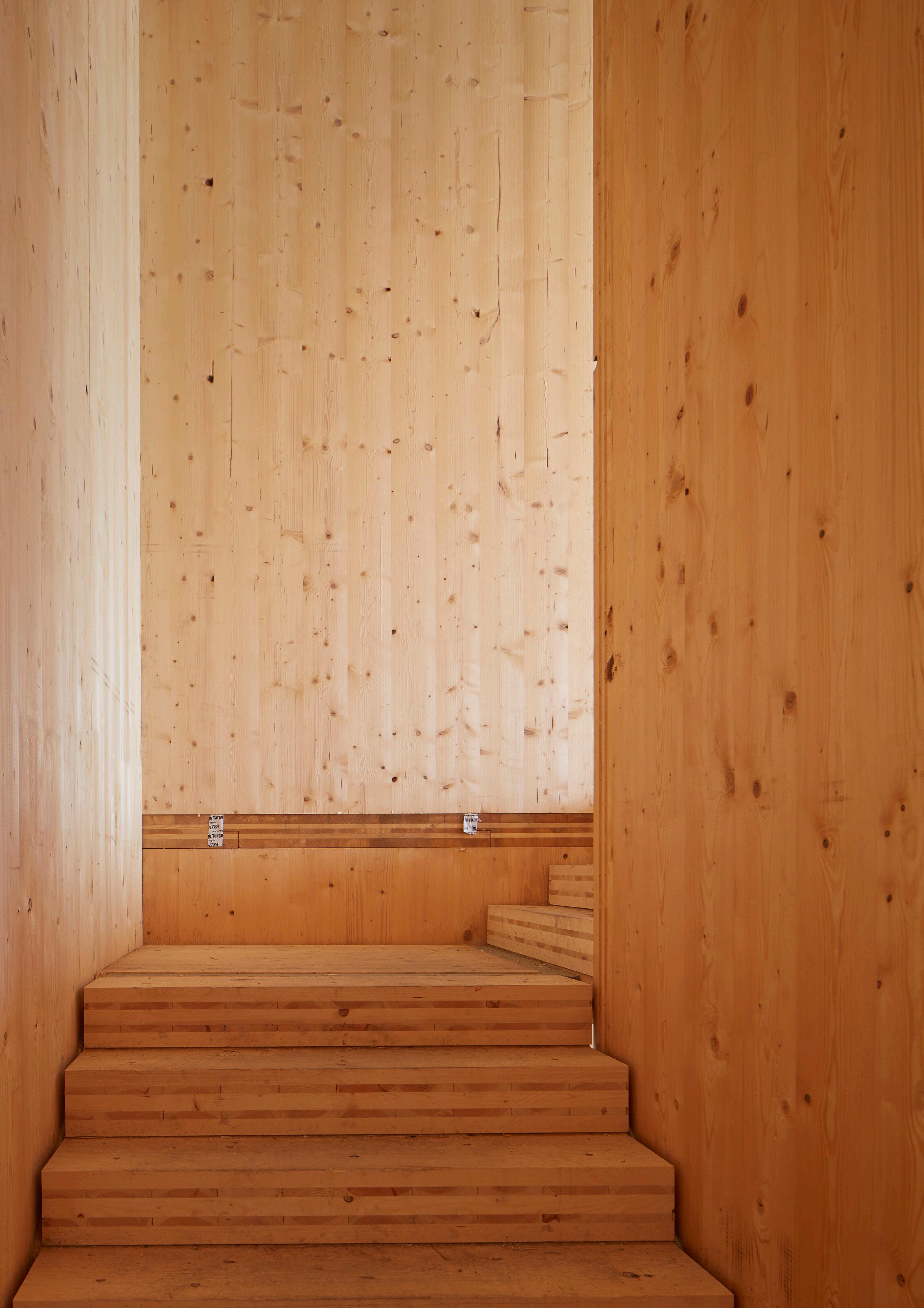
p4 Curtain Place ©Will Pryce
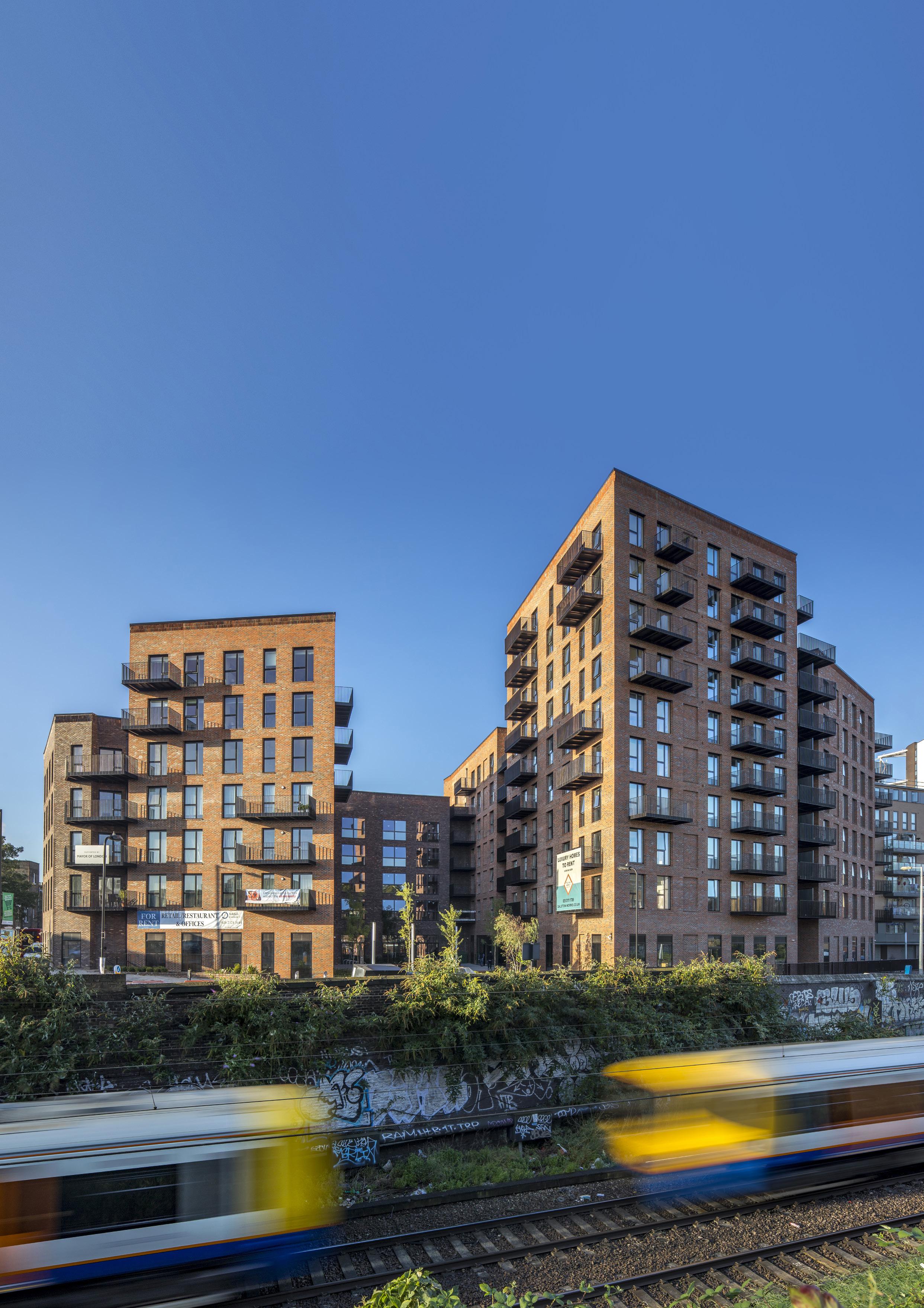
p6 Dalston Works, photo ©Daniel Shearing
p28 Murray Grove ©Will Pryce