NEW MODEL BUILDING
EVIDENCE
Version 1.0
This book is 3 of 3.
Please scan this QR code using your phone for a digital version of the three documents.
Published 2023 by
Waugh Thistleton Architects
35 Pitfield Street
London, N1 6HB
If you would like to know more about the New Model Building please contact Waugh Thistleton Architects info@waughthistleton.com.
DISCLAIMER
The New Model Building is a set of design principles that demonstrates a methodology for building mid-rise residential properties using a low-carbon engineered timber structure. This has been prepared for Build by Nature in collaboration with other professionals including structural engineers and fire specialists. All involved have exercised reasonable skill and care to develop a methodology that performs to the relevant standards, UK Building Regulations and NHBC technical standards current at the time of writing, if correctly implemented.
These details and supporting information are provided on an ‘as is’, ‘with all faults’ basis, and no warranties, guarantees, conditions or other terms are given or implied.
This study was prepared for Built by Nature and is not to be relied upon by any third party. The use of this methodology and information does not relieve any consultant of their responsibility to ensure the suitability, performance, compliance and robustness of their designs and we expressly exclude liability to any party for any loss or damage (whether direct or indirect, and whether or not foreseeable) arising from the use of the following information.
CONTENTS NEW MODEL BUILDING DESIGN PHILOSOPHY MANUAL 5 NEW MODEL BUILDING STRUCTURAL DESIGN PHILOSOPHY 27 NEW MODEL BUILDING FIRE PHILOSOPHY MANUAL 39
NEW MODEL BUILDING DESIGN PHILOSOPHY MANUAL
NEW MODEL BUILDING
DESIGN PHILOSOPHY MANUAL
TEAM: Waugh Thistleton Architects; UCL Department of Civil, Environmental & Geomatic Engineering; Buro Happold
DOCUMENT AUTHOR: Waugh Thistleton Architects
REFERENCE NUMBER: 1_665
REVISION NUMBER: Rev. 05 (16 08.23)
ISSUE DATE:
1
NEW MODEL BUILDING DESIGN PHILOSOPHY MANUAL 2 1.0 INTRODUCTION 5 Purpose 5 Supporting information 5 Definitions 5 2.0 STANDARDS AND CODES OF PRACTICE 5 3.0 LIMITATIONS 6 4.0 PROVISION OF INFORMATION 7 System drawings 7 Performance specification 7 5.0 STRUCTURAL STRATEGY 8 6.0 FIRE STRATEGY 8 7.0 CONSTRUCTION OF EXTERNAL WALLS 10 General approach 10 Standards and compliance 10 Structural performance 10 Fire performance 10 Acoustic performance 10 LSF system 10 Vapour control layers 10 Breather membranes 11 Rainscreen Insulation 11 External cladding 11 Sheathing board 12 Wall lining system 12 Penetrations 12 Parapet walls and lift overruns 12 Sequencing 13 8.0 CONSTRUCTION OF INTERNAL LOAD BEARING ELEMENTS: WALLS, FLOORS, COLUMNS AND BEAMS 15 General approach 15 Standards and compliance 15 Structural performance 15 Fire performance 15 Acoustic performance 15
NEW MODEL BUILDING DESIGN PHILOSOPHY MANUAL 3 Differential movement 15 Engineered timber performance criteria 15 Fabrication tolerances for engineered timber 16 Erection of engineered timber 16 Linings and finishes 17 Penetrations 17 Timber preservation 17 Insulation 18 9.0 CONSTRUCTION OF INTERNAL PARTITIONS 18 General approach 18 10.0 CONSTRUCTION OF GROUND FLOOR SLABS 18 General approach 18 11.0 CONSTRUCTION OF ROOFS AND TERRACES 18 General approach 18 Standards and compliance 19 Structural performance 19 Fire performance 19 Acoustic performance 19 Engineered timber performance criteria 19 Fabrication tolerances for engineered timber 19 Erection of engineered timber 20 Timber preservation 20 Lightweight timber performance criteria 21 Linings and finishes 21 Penetrations 21 12.0 CONSTRUCTION OF BALCONIES 21 General approach 21 Sequencing 22 13.0 DOORS, WINDOWS AND GLAZING 24 General approach 24 14.0 STAIRCASES 24 General approach 24 15.0 SERVICES 24 General approach 24
NEW MODEL BUILDING DESIGN PHILOSOPHY MANUAL 4 16.0 MOISTURE PROTECTION OF STRUCTURAL TIMBER 24 General approach 24 Moisture management through design 25 Moisture management during construction 27 Moisture management post completion 30 Remediation Strategy 30
1.0 INTRODUCTION
PURPOSE
The New Model Building Design Philosophy is a methodology for building residential developments under 18m in height with a low carbon engineered timber structure coupled with a non-combustible façade system.
Demonstrating a compliance based approach, the New Model Building Design Philosophy meets the requirements of the Building Regulations Approved Documents as well as the Structural Timber Association’s latest guidance.
SUPPORTING INFORMATION
The New Model Building Design Philosophy comprises a written manual that details the principles of construction for key building elements, a suite of drawings that illustrate the design and a specification document that outlines minimum performance requirements.
D EFINITIONS
Air and vapour contr ol layer (AVCL) Continuous layer of impermeable material to prevent the movement of air and water vapour.
Balcony Accessible external amenity platform over an open space above ground level, with direct access from a building.
CLT Cross laminated timber
Flat roof A roof with a maximum slope of less than 10 degrees from the horizontal.
Glulam Glue laminated timber
LSF Light steel frame. ‘LSF’ refers to construction framing members made from cold-formed profiles 0.7-4.0mm thick.
Pitched roof A roof with a maximum slope of greater than 10 degrees from the horizontal. Sheathing Board applied to the outside of the steel frame (installed where required by the design).
Terrace External surface for amenity use, above an internal space, above ground level and with direct access from a building.
2.0 STANDARDS AND CODES OF PRACTICE
The information provided outlines principles that are specific to the New Model Building Design Philosophy – this should be viewed as supplementary guidance and should not replace existing standards.
The New Model Building Design Philosophy should be read alongside all relevant Building Regulations and Approved Documents, British Standards and NHBC Technical Standards 2023
NEW MODEL BUILDING DESIGN PHILOSOPHY MANUAL 5
Those who use the New Model Building Design Philosophy should ensure their designs meet the relevant and required standards and codes of practice.
The New Model Building Design Philosophy uses a guidance based route to Building Regulation compliance Where we refer to authoritative documents such as British Standards, the documents should be the editions current at the time of Building Regulation approval.
Alongside the Building Regulations and Approved Documents, British Standards and NHBC Technical Standards 2023, designers must refer to the following guidance:
GENERAL
- TRADA’s National Structural Timber Specification For Building Construction Version 2.0.
- TRADA Cross-laminated Timber Design and Performance
- SCI Technical Report ED017 Design and Installation of Light Steel External Wall Systems
FIRE
- STA Structural Timber Buildings Fire Safety In Use Guidance Volume 6 - Mass Timber Structures; Building Regulation compliance B3(1) STA fire safety and guidance project Version 2.1 May 2023
- STA 16 Steps to fire safety. Promoting good practice on construction sites. Version 4.3 October 2017
MOISTURE MANAGEMENT
- Swedish Wood/TDUKs Moisture-proof CLT construction without a full temporary shelter Edition 1:2022
- STA Moisture management strategy, process guidance for structural timber buildings, Version 1.0, July 2022
- STA Advice Note 14 - Robustness of CLT Structures - Part 1 - Key principles for moisture durability
- STA Technical Note 23 - Durability by design – mass timber structures – STA 2021-
- STA Technical Note 24 - Moisture protection during construction
3.0 LIM ITATIONS
The use of the New Model Building Design Philosophy is limited to the following:
Typology Residential (dwellings) in accordance with ‘Table 0.1 Classification of purpose groups’ as found in Approved Document B (fire safety) volume 1: Dwellings, 2019 edition incorporating 2020 amendments
NEW MODEL BUILDING DESIGN PHILOSOPHY MANUAL 6
Height Less than 18m, measured in accordance with Diagram D4 as found in Approved Document B (fire safety) volume 1: Dwellings, 2019 edition incorporating 2020 amendments
Sprinklers Sprinklers should be installed throughout the building in accordance Approved Document B (fire safety) volume 1: Dwellings, 2019 edition incorporating 2020 amendments
Compartment The minimum fire resistance of compartments should be 60 minutes, in accordance with ‘Table B4 Minimum periods of fire resistance’ as found in Approved Document B (fire safety) volume 1: Dwellings, 2019 edition incorporating 2020 amendments
Location England and Wales
Classification Consequence Class 1, 2A or 2B
4.0 PROVISION OF INFORMATION SYSTEM DRAWINGS
A full register is provided outlining all drawings currently included in the New Model Building Design Philosophy. These include:
1 GA drawings The building shown in the GA drawings is intended as a guide to locate typical details and not a proposed development the size and scale of the building can change according to the brief. Use the plans and sections as a tool to navigate the details and understand their application only.
2 Fire strategy drawings These outline the compartmentation principles of the New Model Building Design Philosophy. The construction details are contingent on this approach.
3 Technical details Key junctions between construction elements are provided at 1:5. These illustrate building materials and design methodology.
4 Performance Specification Key performance requirements of relevant construction elements
All drawings have been labelled to show the importance of each fire and moisture protective item. Building elements and materials that have a specific required fire performance or are particular to the New Model Building Design Philosophy are highlighted. Labels for these are shown in CAPITAL LETTERS provided with a numerical specification reference, for example:
FIRE RESISTANT GAP SEALER (312 )
Further annotations that are provided to give context to the detail, but are not specific to New Model Building Design Philosophy are provided in lower case text, for example:
Acoustic flanking strip
PERFORMANCE SPECIFICATION
NEW MODEL BUILDING DESIGN PHILOSOPHY MANUAL 7
A specification of relevant items has been provided along with their minimum New Model Building performance requirements. This outlines fire performance, with the expectation that other performance requirements are project specific and should meet the minimum requirements of all relevant Building Regulations and Approved Documents, British Standards and NHBC Technical Standards 2022.
5.0 STRUCTURAL STRATEGY
Please refer to the New Model Building Structural Philosophy Manual by Buro Happold
6.0 FIRE STRATEGY
Please refer to the New Model Building Fire Philosophy Manual by UCL
A Qualitative Design Review (QDR) in relation to fire safety standards BS 7974 will be required on all schemes that adopt this Design Philosophy, as per STA Guidance. Client and design teams using The New Model Building Design and Fire Philosophy will need to develop a fire strategy specific to their proposal which will be assessed by building control and NHBC on a case by case basis.
This document does not include a Fire Safety Management and Emergency Plan. A fire safety management plan details the arrangements to implement, control, monitor and review fire safety standards and to ensure those standards are maintained under Article 11 of the Regulatory Reform (Fire Safety) Order 2005. It must be produced by the responsible person but should be fully aligned with the UCL Fire Report.
Redundancy in the UCL fire strategy is described at high level in Figure 1.
FIRE PREVENTION AND CONTROL DURING CONSTRUCTION
Please refer to the Structural Timber Association’s ‘16Stepstofiresafety:Promotinggood practiceonconstructionsites’.
NEW MODEL BUILDING DESIGN PHILOSOPHY MANUAL 8
5. BUILDING FIRE STRATEGY
Every building using the NMB Guidance will need their own fire engineer and fire strategy which will be assessed by NHBC case by case The NMB does not include a F ire Safety Management and Emergency Plan. A fire safety management plan details the arrangements to implement, control, monitor and review fire safety standards and to ensure those standards are maintained under Article 11 of the Regulatory Reform (Fire Sa fety) Order 2005. It must be produced by the responsible person but should be fully aligned with the UCL Fire Report.
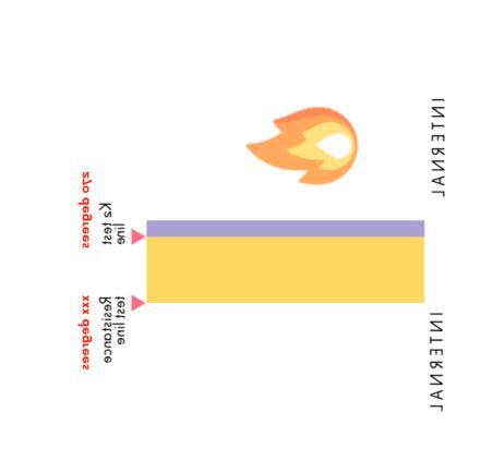
4. NHBC QUESTIONS What about quality of workmanship? The system is described through details and sequencing diagrams if not installed correctly t he liability lies with the installer not with NHBC . If plasterboard fails CLT still achieves RE I 60. What about STA Guidance? We will specify compliance with STA guidance –achieving 200 degrees on the face of the CLT behind the plasterboard Is it mixing a matching? Both tests K 2 and REI are described in BS EN135012 Belt and Braces approach to performance. CLT protected more than it would be with a CLT and plasterboard REI60 test What if the fire spr eads through sockets? REI test includes service hole penetrations in the test
3. BS EN 135012 TESTS K 2 60Standard Protection Timber not involved in the fire Max Temp on inside surface 2 7 0 degrees prevents pyrolysis K 2 60 –STA modified Protection Timber not involved in the fire Max Temp on inside surface 200 degrees 70 degree safety factor included. REI 60 –CLT only Demonstrates that CLT retains integrity, load bearing capacity and insulation to 60 mins Lots of CLT manufacturers have done this test REI 90 –CLT with board Demonstrates that CLT with board retains integrity, load bearing capacity and insulation to 90 mins K2 60 STA modified + REI 60 for CLT only Timber not involved in the fire Max Temp on inside surface 200 degrees includes 70 degree safety factor + CLT retains REI integrity, load bearing capacity and insulation to 60 mins
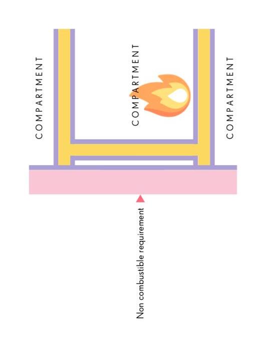
2. SPRINKLERS + COMPARTMENTATION
1. NO COMBUSTIBLES IN EXTERNAL WALL
1 Fire protection redundancy


NEW MODEL BUILDING DESIGN PHILOSOPHY MANUAL 9
FIRE PERFORMANCE REDU N DA C Y IN NMB
Up to 945 degree s in 60 mins
Up to 945 degree s in 60 mins Up to 945 degree s in 60 mins Up to 945 degree s in 60 mins 2 7 0° 170° Less than 170 ° 200°
Fig
7.0 CONSTRUCTION OF EXTERNAL WALLS
GENERAL APPROACH
The design utilises a non-combustible external wall system (EWS) constructed from materials as defined in Approved Document Part B, Requirement B4: External fire spread - Regulation 7 –Materials and workmanship In line with this, all materials within the external wall system are of European Classification A2-s1, d0 or A1, or better classified in accordance with BS EN 13501.
The EWS is not designed to be load bearing, and is constructed from a continuous LSF system, supported from the floor slab, with a ventilated rainscreen cladding system.
STANDARDS AND COMPLIANCE
The designer must ensure each element of the EWS meets the relevant codes and standards.
STRUCTURAL PERFORMANCE
Refer to Structural Philosophy Manual for further details.
FIRE PERFORMANCE
Refer to Fire Philosophy Manual and Fire Performance Specification documents for further details.
ACOUSTIC PERFORMANCE
Acoustic performance is project specific and therefore designer must ensure that the EWS meets the relevant British Standards and local planning guidance concerning acoustic performance that are applicable to their design.
LSF SYSTEM
The LSF system follows the principles of continuous walling LSF systems, where the LSF over sails the edge of the primary structure and is fixed to the slab via connection brackets.
Further guidance and requirements can be found in the following documents: - SCI Technical Report ED017 Design and Installation of Light Steel External Wall Systems
For minimum specification requirements as defined by the New Model Building design, refer to item 321 in [Fire Performance Specification]
VAPOUR CONTROL LAYERS
An airtight vapour control layer (AVCL) should be applied to the internal lining of the EWS.
NEW MODEL BUILDING DESIGN PHILOSOPHY MANUAL 10
At party wall/floor locations, the AVCL will be sealed against the engineered timber to ensure continuous airtightness across the external wall, as shown in Standard Details including:
1_665-WTA-00-XX-DR-A-4001 Typical Slab Edge – Plan r02
1_665-WTA-00-XX-DR-A-4002 Typical Slab Edge – Section r02
1_665-WTA-00-XX-DR-A-4003 External Wall to Column – Plan r02
1_665-WTA-00-XX-DR-A-4004 External Wall to Column – Section r02
1_665-WTA-00-XX-DR-A-4012 Balcony Detail – Section r02
All joints and penetrations in the AVCL should be lapped and taped in accordance with the manufacturer’s guidance Adhesive tapes (or sealants) should be used to seal window/door frames and membrane interface To maintain air and vapour sealing, the window to membrane interface must also be sealed to prevent condensation occurring behind the frame.
For minimum specification requirements as defined by the New Model Building design, refer to item 352 in [Fire Performance Specification]
BREATHER MEMBRANES
Breather membranes should be installed to the outer face of the sheathing board
All joints and penetrations in the breather membrane should be lapped and taped in accordance with the manufacturer’s guidance. Adhesive tapes (or sealants) should be used to seal window/door frames and membrane interface. To maintain air and vapour sealing, the window to membrane interface must also be sealed to prevent condensation occurring behind the frame.
For minimum specification requirements as defined by the New Model Building design, refer to item 351 in [Fire Performance Specification]
RAINSCREEN I NSULATION
Rainscreen insulation should be resilient to moisture to allow the breather membrane to be installed behind.
For minimum specification requirements as defined by the New Model Building design, refer to item 332 in [Fire Performance Specification]
EXTERNAL CLADDING
Cladding materials are not defined by the New Model Building system and should be designed in accordance with NHBC Technical Standards 2022 and BS 8200:1985 Code of Practice for the Design of Non-loadbearing External Vertical Enclosures of Buildings.
NEW MODEL BUILDING DESIGN PHILOSOPHY MANUAL 11
Example materials that could be applied include non-combustible lightweight cladding materials such as brick slips, clay tiles or fibre cement panels. Cladding materials should be coordinated with window and door openings and the setting out of cladding materials accommodate these.
Cladding specified for use at GF may be considered to fall within Use Class A (publicly accessible, vandal prone) or B (not vandal prone). As such, cladding specification - to a height of 1.5m above ground - will need to be suitable for Use Class A (publicly accessible, vandal prone) or B (not vandal prone) and meet the requirements of BS 8200:1985 - or other potential equivalent acceptable to NHBC, e.g. EN 13497:2002, MOAT 43:1987. Designers might also refer to CWCT's TN 75 Impact Performance of Building Envelopes: Guidance on Specification.
All cladding solutions will require cavities to be closed at the top and bottom of walls, as well as around openings and penetrations, in addition to those at separating walls and floors.
For minimum specification requirements as defined by the New Model Building design, refer to item 333 in [Fire Performance Specification]
SHEATHING BOARD
Sheathing boards should be protected during construction; this can be provided through the breather membrane that is installed on the outside face of the sheathing board.
Up to 60 minutes can be achieved for minimum specification requirements as defined by the New Model Building design, refer to item 323 in [Fire Performance Specification]
WALL LINING SYSTEM
Internal wall lining boards provide finish encapsulation to the external wall system. External wall build-up and products specified must demonstrate fire performance of REI 60 minutes.
For minimum specification requirements as defined by the New Model Building design, refer to item 318 in [Fire Performance Specification]
PENETRATIONS
In general, penetration locations and sizes should be coordinated to minimise the amount of openings and voids that need to be filled Typical penetrations shown in the standard details demonstrate example methods for fire stopping to ensure the fire performance of the wall is maintained around the opening On each project, the designer must seek confirmation from the manufacturer that the specified fire stopping products are suitable to be used in each application and will achieve the required 60 minutes REI fire performance. This could be through following manufacturer’s standard details or through project specific, bespoke engineering judgements.
PARAPET WALLS AND LIFT OVERRUNS
NEW MODEL BUILDING DESIGN PHILOSOPHY MANUAL 12
Parapet walls, lift overruns and any other such walls that enclose the building must be constructed as external walls and follow the principles outlined in this chapter and Standard Details including:
1_665-WTA-00-XX-DR-A-4031 Roof_Core Junction Detail – Section r02
1_665-WTA-00-XX-DR-A-4032 Roof Parapet Detail – Section r02
Note that parapet walls must not be constructed from CLT or other timber components.
SEQUENCING
The principles for connecting the EWS to the structure have been illustrated in the included details and the sequencing of works is illustrated in the following sequencing diagrams see Fig 2 below.
NEW MODEL BUILDING DESIGN PHILOSOPHY MANUAL 13
NEW MODEL BUILDING DESIGN PHILOSOPHY MANUAL 14 1 ENGINEERED TIMBER STRUCTURE 4 LIGHT STEEL FRAMING SYSTEM FIXED TO ENGINEERED TIMBER SLAB. 2 LINEAR FIRESTOP FIXED TO SLAB 5 FULL FILL INSULATION APPLIED TO SLAB EDGE. 6 SHEATHING BOARD ADDED. 9 HELPING HAND BRACKETS INSTALLED 3 FAÇADE/SLAB CONNECTIONS FIXED TO ENGINEERED TIMBER STRUCTURE. 7 BREATHER MEMBRANE INSTALLED. ALL JOINTS/PENETRATIONS LAPPED AND TAPED. 10 RAINSCREEN INSULATION INSTALLED 11 FIXING SYSTEM INSTALLED. 12 CLADDING INSTALLED. 14 VAPOUR CONTROL LAYER INSTALLED AND TAPED TO ENGINEERED TIMBER STRUCTURE. ALL JOINTS/PENETRATIONS LAPPED/TAPED. 13 WALL LINING INSULATION INSTALLED TO LIGHT STEEL FRAMING SYSTEM 15 ENCAPSULATION APPLIED TO STEEL BALCONY CONNECTIONS. 8 HORIZONTAL CAVITY BARRIER INSTALLED AT SLAB EDGE. 16 FLOOR FINISHED INSTALLED. 17 WALL FINISH AND SKIRTING INSTALLED. SUSPENDED CEILING ADDED Fig
connecting the
the
2 Principles for
EWS to
structure
8.0 CONSTRUCTION OF INTERNAL LOAD BEARING ELEMENTS: WALLS , FLOORS , COLUMNS AND BEAMS
GENERAL APPROACH
The New Model Building utilises a combination of internal load bearing walls, floors, columns and beams constructed from engineered timber. These are fully encapsulated with gypsum board applied to achieve K2-60 classification, all structural timber elements achieve REI60 classification in accordance with BS EN 13501-2 with a max limit temperature of 200 degrees C
S T ANDARDS AND COMPLIANCE
The designer must ensure each element of the of the internal load bearing walls, floors, columns and beams meets the relevant codes and standards.
STRUCTURAL PERFORMANCE
Refer to Structural Philosophy Manual for further details.
FIRE PERFORMANCE
Refer to Fire Philosophy Manual and Fire Performance Specification documents for further details.
ACOUSTIC PERFORMANCE
Acoustic performance is project specific and therefore designer must ensure that the EWS meets the relevant British Standards and local planning guidance concerning acoustic performance that are applicable to their design.
DIFFERENTIAL MOVEMENT
Please refer to the New Model Building Structural Philosophy Manual
ENGINEERED TIMBER PERFORMANCE CRITERIA
General performance criteria for engineered timber can be found in TRADA’s National Structural Timber Specification For Building Construction Version 2.0.
Further guidance and requirements can be found in the following documents:
- Minimum dimensions of timber sections: In accordance with BS EN 1995-1-1.
- Vibration performance: In accordance with BS 6472-1.
NEW MODEL BUILDING DESIGN PHILOSOPHY MANUAL 15
- Design life: In accordance with BS EN 1990:Category 4.
- Wood preservation: DIN 68800
- Procurement: CLT should be obtained from well-managed forests and/or plantations in accordance with PEFC or FSC accreditation schemes.
Use timber products only within the limits recommended by their manufacturer. Do not use timber products that are damaged or apparently defective.
FABRICATION T OLERANCES FOR ENGINEERED TIMBER
- Nominal dimensions of materials:
TheHarmonisedTechnicalSpecificationslists tolerances of nominal dimensions of timber products.
- Dimensions of elements:
Table 2 in prEN 14732 Timberstructures.Structuralprefabricatedwall,floorandroofelements. Requirementslists production tolerances of elements and openings.
ERECTION OF ENGINEERED TIMBER
Setting out
Setting-out the building in accordance with BS5964-1.Buildingsettingoutandmeasurement. Methodsofmeasuring,planningandorganizationandacceptancecriteria . Measure any deviations relative to this system.
Handling and storage
Handle and store components safely and in a manner that minimises the risk of damage. Follow the method of handling and storage in the erection method statement.
Alignment of the structure
Align each part of the timber structure and stair within tolerances as soon as practicable after it has been erected. Do not make permanent connections between panels or elements until a sufficient amount of the structure or stair has been aligned, levelled, plumbed and temporarily connected to ensure that components will not be displaced during subsequent erection or alignment of the remainder of the structure or stair.
Take due account of the effects of temperature on the structure/stair and on tapes and instruments when measurements are made for setting out, during erection, and for subsequent dimensional checks. The reference temperature is 20°C.
Connections
Make permanent connections as work progresses to ensure that the structure remains correctly aligned, levelled and plumbed.
Damaged components
NEW MODEL BUILDING DESIGN PHILOSOPHY MANUAL 16
Assemble the structure in such a way that over-stressing of its members or connections is avoided. Replace members which are warped, split or badly fitting at the joints.
Remedial works
Employer to obtain the Structural Engineer’s and Architect’s acceptance of remedial work. If it is unacceptable to perform remedial work on site, modify or replace defective components before dispatch to site.
LININGS AND FINISHES
Internal load-bearing walls should be fully encapsulated with gypsum board applied to achieve K2-60 classification in accordance with BS EN 13501-2 with a max limit temperature of 200 degrees C
STA publication Vol 6 Fire Safety; Section 2.6.2 Encapsulation advocates a limiting temperature behind the inner lining of 200oC. The New Model Building performance specification for plasterboard reflects this requirement.
For minimum specification requirements as defined by the New Model Building design, refer to item 310 in [Fire Performance Specification]
P ENETRATIONS
Typical penetrations shown in the standard details demonstrate example methods for fire stopping to ensure the fire performance of the wall/floor is maintained around the opening. On each project, the designer must seek confirmation from the manufacturer that the specified fire stopping products are suitable to be used in each application and will achieve the required 60 minutes REI fire performance. This could be through following manufacturer’s standard details or through project specific, bespoke engineering judgements.
TIMBER PRESERVATION
Preservation against House Longhorn Beetles
CLT is reportedly rarely infested by House Longhorn Beetles. According to DIN 68800-2 number 6.3, the use of CLT alone is a measure to prevent infestation and there is no requirement for treatment with a preservative.
However, should additional measures be required, for example when designing in a location known to be at risk from House Longhorn Beetles and treatment is required in accordance with Approved Document A, then a preservative - Imprägnierung Klasse 2 zum Schutz vor Pilz- und Insektenbefall entsprechend DIN 68800, CTB P+ Zertifikat - is regarded to be suitable protection. This treatment can be provided by a number of CLT suppliers and where relevant is referenced with the suppliers EPD or ETA document.
NEW MODEL BUILDING DESIGN PHILOSOPHY MANUAL 17
Preservation ag ainst moisture
The structural timber frame must be protected from moisture during construction and throughout the building’s life.
Moisture protection of structural timber later in this document is dedicated to moisture management in design, during construction and during the life of the building..
INSULATION
The specification of the insulation to internal load bearing elements is not defined by the New Model Building system.
Insulation is shown as part of the internal wall build up for acoustic purposes. These are project specific, and the designer should ensure the specification and properties of the material are suitable for its application.
9.0 CONSTRUCTION OF NON LOAD BEARING INTERNAL PARTITIONS
G ENERAL APPROACH
The design of these is not specific to the system and the designer should ensure compliance with all relevant standards and guidance.
10.0 CONSTRUCTION OF GROUND FLOOR SLABS
GENERAL APPROACH
The design of these is not specific to the system and the designer should ensure compliance with all relevant standards and guidance.
11.0 CONSTRUCTION OF ROOFS AND TERRACES
GENERAL APPROACH
The New Model Building system has two roof construction options: flat roofs (<10o roof angle) or pitched roofs (>10o roof angle) Flat roofs must be constructed from a lightweight timber roof system, whereas pitched roofs can be either constructed from CLT panels or a lightweight timber roof system.
If the overall buliding height exceeds 15 metres, all roof decking within 1.5m of any separating walls must be non-combustible in accordance Approved Document B (Diagram 8.2).
NEW MODEL BUILDING DESIGN PHILOSOPHY MANUAL 18
All parapet walls are to be constructed of non combustible materals and considered as external walls.
STANDARDS AND COMPLIANCE
The designer must ensure each element of the roof and/or terrace design meets the relevant codes and standards.
STRUCTURAL PERFORMANCE
Refer to Structural Philosophy Manual for further details.
FIRE PERFORMANCE
Refer to Fire Philosophy Manual and Fire Performance Specification documents for further details.
ACOUSTIC PERFORMANCE
Acoustic performance is project specific and therefore designer must ensure the roof and/or terrace design meets the relevant British Standards and local planning guidance concerning acoustic performance that are applicable to their design.
ENG INEERED TIMBER PERFORMANCE CRITERIA
General performance criteria for engineered timber can be found in TRADA’s NationalStructural TimberSpecificationForBuildingConstructionVersion2.0.
Further guidance and requirements can be found in the following documents:
- Minimum dimensions of timber sections: In accordance with BS EN 1995-1-1.
- Vibration performance: In accordance with BS 6472-1 and BS EN 1995.1.1
- Design life: In accordance with BS EN 1990:Category 4.
- Wood preservation: DIN 68800
- Procurement: CLT should be obtained from well-managed forests and/or plantations in accordance with PEFC or FSC accreditation schemes.
Use timber products only within the limits recommended by their manufacturer. Do not use timber products that are damaged or apparently defective.
FABRICATION TOLERANCES FOR ENGINEERED TIMBER
- Nominal dimensions of materials: TheHarmonisedTechnicalSpecificationslists tolerances of nominal dimensions of timber products.
NEW MODEL BUILDING DESIGN PHILOSOPHY MANUAL 19
- Dimensions of elements: Table 2 in prEN 14732 Timberstructures.Structuralprefabricatedwall,floorandroofelements. Requirementslists production tolerances of elements and openings.
ERECTION OF ENGINEERED TIMBER
Setting out
Setting-out the building in accordance with BS5964-1.Buildingsettingoutandmeasurement. Methodsofmeasuring,planningandorganizationandacceptancecriteria . Measure any deviations relative to this system.
Handling and storage
Handle and store components safely and in a manner that minimises the risk of damage. Follow the method of handling and storage in the erection method statement.
Alignment of the structure
Align each part of the roof and/or terrace within tolerances as soon as practicable after it has been erected. Do not make permanent connections between panels or elements until a sufficient amount of the structure or stair has been aligned, levelled, plumbed and temporarily connected to ensure that components will not be displaced during subsequent erection or alignment of the remainder of the structure or stair.
Take due account of the effects of temperature on the roof and/or terrace and on tapes and instruments when measurements are made for setting out, during erection, and for subsequent dimensional checks. The reference temperature is 20°C.
Connections
Make permanent connections as work progresses to ensure that the structure remains correctly aligned, levelled and plumbed.
Damaged components
Assemble the structure in such a way that over-stressing of its members or connections is avoided. Replace members which are warped, split or badly fitting at the joints.
Remedial works
Employer to obtain the Structural Engineer’s and Architect’s acceptance of remedial work. If it is unacceptable to perform remedial work on site, modify or replace defective components before dispatch to site.
TIMBER PRESERVATION
Preservation against House Longhorn Beetles
NEW MODEL BUILDING DESIGN PHILOSOPHY MANUAL 20
CLT is reportedly rarely infested by House Longhorn Beetles. According to DIN 68800-2 number 6.3, the use of CLT alone is a measure to prevent infestation and there is no requirement for treatment with a preservative.
However, should additional measures be required, for example when designing in a location known to be at risk from House Longhorn Beetles and treatment is required in accordance with Approved Document A, then a preservative - Imprägnierung Klasse 2 zum Schutz vor Pilz- und Insektenbefall entsprechend DIN 68800, CTB P+ Zertifikat - is regarded to be suitable protection. This treatment can be provided by a number of CLT suppliers and where relevant is referenced with the suppliers EPD or ETA document.
Preservation ag ainst moisture
The roof and/or terrace must be protected from moisture during construction and throughout the building’s life.
When designing roof elements, condensation risk should be considered in accordance with BS 5250.
Refer to Moisture protection of structural timber for further details.
LIGHTWEIGHT TIMBER
PERFORMANCE CRITERIA
Designers should follow the guidance in NHBC Technical Standards 2022 for the design of lightweight timber roofs.
LININGS AND FINISHES
The specification of roof coverings should be in accordance with AD Part B and as designated by BS 9991:2015 Table 8 or equivalent European classifications.
PENETRATIONS
Typical penetrations shown in the standard details demonstrate example methods for fire stopping to ensure the fire performance of the roof is maintained around the opening. On each project, the designer must seek confirmation from the manufacturer that the specified fire stopping products are suitable to be used in each application and will achieve the required 60 minutes REI fire performance. This could be through following manufacturer’s standard details or through project specific, bespoke engineering judgements.
12.0
CONSTRUCTION OF BALCO NIES
GENERAL APPROACH
NEW MODEL BUILDING DESIGN PHILOSOPHY MANUAL 21
Where required, the New Model Building system uses prefabricated steel balconies, either fixed to the engineered timber structure or as independent steel structures The design of these is not specific to the system and the designer should ensure compliance with all relevant standards and guidance.
Following the principles shown in the standard details, designers should ensure the steel balcony bracket is fully encapsulated with gypsum board applied to achieve K2-60 classification in accordance with BS EN 13501-2 and surrounded by cavity barriers with infilled mineral wool insulation.
Waterproofing should be continued around the balcony connections. Liquid waterproofing should be applied to the steel balcony bracket Balcony connectors should be thermally broken.
SEQUENCING
The principles for connecting the balcony to the structure have been illustrated in the included details and the sequencing of works is illustrated in the following sequencing diagrams in Fig 3:
NEW MODEL BUILDING DESIGN PHILOSOPHY MANUAL 22
NEW MODEL BUILDING DESIGN PHILOSOPHY MANUAL 23 2 . STEEL BALCONY BRACKET FIXED TO ENGINEERED TIMBER STRUCTURE 3 . LIQUID WATERPROOFING SEALANT APPLIED TO STEEL BALCONY BRACKET 7 LIGHT STEEL FRAMING SYSTEM FIXED TO ENGINEERED TIMBER SLAB 10 SHEATHING BOARD ADDED 5 . THERMALLY BROKEN BALCONY CONNECTOR FIXED TO STEEL BALCONY 8 . BALCONY FIXING INSTALLED 9 FULL FILL INSULATION APPLIED TO SLAB EDGE 11 . BREATHER MEMBRANE INSTALLED. ALL JOINTS/PENETRATIONS LAPPED AND TAPED. 14 . RAINSCREEN INSULATION INSTALLED 4 . LINEAR FIRESTOP FIXED TO SLAB 6 . FAÇADE/SLAB CONNECTIONS FIXED TO ENGINEERED TIMBER STRUCTURE 12 . CAVITY BARRIERS INSTALLED AT SLAB EDGE AND SURROUNDING BALCONY FIXING, INFILLED WITH MINERAL WOOL 13 HELPING HAND BRACKETS INSTALLED 15 . FIXING SYSTEM INSTALLED 1 ENGINEERED TIMBER STRUCTURE 16 CLADDING AND FASCIA BOARD INSTALLED 17 PREFABRICATED BALCONY INSTALLED 18 . WALL LINING INSULATION INSTALLED TO LIGHT STEEL FRAMING SYSTEM 19 . VAPOUR CONTROL LAYER INSTALLED AND TAPED TO ENGINEERED TIMBER STRUCTURE. ALL JOINTS/PENETRATIONS LAPPED/TAPED. 20 ENCAPSULATION APPLIED TO STEEL 21 . FLOOR FINISH INSTALLED 22 . WALL FINISH AND SKIRTING INSTALLED. Fig 3 Principles for connecting the balcony to the structure
13.0 DOORS, WINDOWS AND GLAZING
GENERAL APPROACH
The design of these is not specific to the system and the designer should ensure compliance with all relevant standards and guidance.
14.0
STAIR CASE S
GENERAL APPROACH
The design of these is not specific to the system and the designer should ensure compliance with all relevant standards and guidance.
15.0
SERVICES
GENERAL APPROACH
The design of these is not specific to the system and the designer should ensure compliance with all relevant standards and guidance.
16.0 MOISTURE PROTECTION OF STRU CTURAL
TIMBER
GENERAL APPROACH
Once timber products absorb water above the intended in-service moisture content, then loss of strength, dimensional changes and a higher likelihood of decay will occur. Different structural timber products and species behave differently.
The designer should consider how to reduce the risk of damage from moisture through all project stages. Early consideration of how to minimise moisture damage while the building is in use can reduce the likelihood and severity of leaks and related damage. A comprehensive on-site Risk Assessment and Method Statement (RAMS), moisture management control plan (MMCP) and protocol should be developed prior to construction and a post completion check list should be provided at handover describing how to assess and carry out remedial work after the building is occupied.
In defining a project specific moisture management plan and designing effectively for moisture durability, designers must refer to:
- Swedish Wood/TDUKs Moisture-proof CLT construction without a full temporary shelter Edition 1:2022
NEW MODEL BUILDING DESIGN PHILOSOPHY MANUAL 24
- STA Moisture management strategy, process guidance for structural timber buildings, Version 1.0, July 2022
- STA Advice Note 14 - Robustness of CLT Structures - Part 1 - Key principles for moisture durability
- STA Technical Note 23 - Durability by design – mass timber structures – STA 2021-
- STA Technical Note 24 - Moisture protection during construction
It is important to consider the following in designing to avoid moisture damage: Moisture damage can be split into 2 categories; during construction and during the lifetime of the building. The comprehensive documents above clearly describe the potential issues of both and how to mitigate them
MOISTURE MANAGEMENT THROUGH DESIGN
During the design process, designers must pay careful attention to the detailing of areas at highest risk of leaks/moisture damage, such as: roofs; ‘wet’ areas with active plumbing fixtures; areas in contact with the ground floor slab and connections and fixings. Protection from moisture can be provided through a range of measures, from careful detailing and preventive designs to including practical measures for leak detection such as automatic cut-off valves. A vapour control layer must be provided to all walls and ceilings unless condensation risk analysis shows it is not required.
Roofs and terraces
This section only describes the principles for moisture management during the design of roofs and terraces. For further details on the wider design principles for roofs and terraces, please refer to the relevant chapter Construction of roofs and terraces
For CLT roof decks a minimum roof angle of 1:5.5/10o is required. Other lightweight roof systems must allow for a minimum fall of 1:40/1.5o so water can run off. Terraces must be constructed from a lightweight system and allow for a minimum fall of 1:40/1.5o so water can run off.
Condensation risk analysis must be carried out for the construction build-up of all timber roofs and terraces, analysing the type, thickness and location of the insulation material Should it be found that there is a risk of condensation, the build-up must be redesigned to mitigate the risk.
Proprietary waterproofing systems applied to roofs and terraces should be expected to fail during the building’s lifespan, therefore the design must prevent an accumulation of standing water The designer needs to consider ways to ensure the early detection of moisture. Examples of this include:
- Provision of overflow outlets to all roof areas to discharge standing water
- Provide small pilot holes in the roof/terrace structure at the lowest point of deflection This can alert building occupiers to standing water leaks will become apparent more quickly
NEW MODEL BUILDING DESIGN PHILOSOPHY MANUAL 25
- Provide inspection holes under gutters to parapets
Low level areas
The New Model Building system does not permit timber to be installed as part of the external wall system.
Where engineered timber internal load bearing walls or columns are in contact with the ground floor slab the bottom of the timber must be at or above the internal finished floor level on a brick, block or concrete upstand, a DPC and end grain sealant should be installed in accordance with 1_665-WTA-00-XX-DR-A-4007 GF Slab Details – Section r03 and 1_665-WTA-00-XX-DR-A4008 GF_Column Details – Section r02 to prevent moisture from wicking into the timber. Note: end grain sealers are not waterproof and do not prevent timber from absorbing moisture, they merely slow the process, elevating timber to above FFL reduces the risk of the timber coming into contact with moisture.
‘ W et ’ areas
The design team should identify all areas in the building with active plumbing fixtures or appliances Typically, these include bathrooms and kitchens, but also additional areas such as utility cupboards, cleaning facilities and cycle/refuse stores.
Protection and risk reduction strategies need to be implemented in all identified wet areas. These areas can be designed with localised timber joist construction:
- Localised timber joist construction Install a timber joisted floor locally throughout the wet area. This reduces the risk of structural damage, improves drying times and allows for simplified remediation if needed.
or at least two of the following strategies should be adopted to ensure the use of timber is kept within Service Class 1:
- Tanking membrane Install a tanking membrane to a minimum of 1200mm AFFL throughout the wet area with a full height tanking membrane applied to areas of heavy exposure such as showers and baths. Additional protection can be provided by linking the tanking membrane to a gully that connects with the main waterproofing line e.g., tiles and grout with sanitary fixtures and bathroom furniture installed above. This mitigates the risk of water damage should a tap or pipe leak or an element overflow.
- System leak detection monitor A ‘smart’ leak detection monitor should be installed to the mains water connection, monitoring the building’s water flow and pressure. A valve associated with the monitor will automatically shut off the supply should a leak be detected to reduce consequential damage. Leak detection to be in accordance with BS EN 131601:2016 Leak detection systems.
NEW MODEL BUILDING DESIGN PHILOSOPHY MANUAL 26
- Local leak detection system A ‘smart’ leak detection needs to be installed in all high risk locations, such as under/near plumbing fixtures When water or high humidity occurs, sensors set off a physical alarm or trigger an alert sent via WiFi to the building management system. Detectors connected to mains power with battery back up must be used to ensure continuity of protection. Leak detection to be in accordance with BS EN 13160-1:2016 Leak detection systems.
- Ventilation zone Provide provision for a 50mm ventilation zone to allow any moist timber to dry out.
- Preservative treatment Apply a service class 2 treatment to WPA guidance. Timber elements can be factory treated or treatment can be site applied. Information on treatment needs to be sent and confirmed with NHBC prior to application and installation.
MOISTURE MANAGEMENT DURING CONSTRUCTION
When designers/developers submit an application to NHBC using the New Model Building Philosophy they must incorporate a Risk Assessment and Method Statement (RAMS) to outline the design, methods, and requirements for protecting the system from weather exposure and mechanical damage during storage, transportation and installation.
Engineered timber is vulnerable to moisture damage during construction, which can come from several sources: precipitation, humidity, ambient sources, and mechanical, plumbing and fire protection trades Therefore, the project team must ensure that as part of the RAMS an on-site moisture management control plan (MMCP) is provided before construction, for use during fabrication, delivery to site, erection and delivery phases. MMCPs must be specific to the project, and form part of the construction management plan submitted as part of any tender return. MMCPs must be developed in conjunction with the timber supplier and project engineer.
Refer to the following guidance for details of what should be included in an MMCP:
- TRADA’s National Structural Timber Specification, Section 4.7: Moisture Content Control Plan
- Swedish Wood/TDUKs Moisture-proof CLT construction without a full temporary shelter Edition 1:2022
- STA Moisture management strategy, process guidance for structural timber buildings, Version 1.0, July 2022
- STA Technical Note 23 - Durability by design – mass timber structures – STA 2021https://members.structuraltimber.co.uk/get-download/16129
- STA Technical Note 24 - Moisture protection during construction
The MMCP should include moisture management statements that will include but not be limited to a methodology for the following, where relevant:
- removing free water and snow immediately
- the design of temporary weather protection to avoid the risk of standing water on tops of volumetric units
NEW MODEL BUILDING DESIGN PHILOSOPHY MANUAL 27
- Specification of sheeting used for damp-proofing which must be breathable. Membranes must be specified to ensure they are fit for purpose and achieve compliance with NHBC Technical Requirement R4 c) iii) proper protection during storage and v) protection against weather during construction (including excessive heat, cold, wetting or drying)
- a statement on the maximum duration that temporary water protection measures can be applied Exposure time limits for protection materials e.g., unit wrappings, breather membranes, roof membranes shall be controlled for both external storage and following installation until permanent claddings are installed.
- Details of any temporary openings that may be required in the protection layers – e.g., for lifting installation/ connection of units.
- how water can escape and how suitable means of ventilation can be implemented in conjunction with regular quality assurance checks
- CLT elements with high moisture content must dry out, moisture checks must be conducted on an ongoing basis The surface moisture content should be no more than 18 % prior to enclosure
- damp-proofing of end-grain wood, element joints and connections.
- the process for ensuring the continuity of temporary weathering post installation and quality assurance checks
- How seals between units and sealing around lifting points are installed.
- the choice of protection materials shall be suitable for use in cold or wet conditions
- ensure UV exposure of protective membranes does not cause degradation
The new model building does not have any timber external walls or balconies however at certain details and connections, it is particularly important to check the moisture content regularly throughout the construction phase, in line with the established inspection plan:
- Element joints
- Wall to floor joints
- Windows and door openings
- Stairwells and shafts
- Cut-outs.
On - site moisture measurements
The expected moisture content of mass timber in the finished building is in the range of 14-18%. The moisture content of engineered timber elements must be recorded in an on-site moisture monitoring document. This must include a matrix of components alongside their target moisture contents at key milestones, for example:
Walls CLT Stairs
NEW MODEL BUILDING DESIGN PHILOSOPHY MANUAL 28
content After fabrication Before erection At handover
Component Moisture
CLT
Refer to BM Trada’s WIS 4-14 Moisture in timber and BS EN 13183-2:2002 for further information on moisture measurement and Swedish Wood/TDUKs Moisture-proof CLT construction without a full temporary shelter Edition 1:2022 for instruction on the type of moisture probes to use and how to use them.
Timber in stallation programme and critical follow - on trades
The construction programme should ensure engineered timber is covered as soon as installation is complete. The contractor should allow for the provision of interim protection should any unforeseen changes to the programme occur, such as delays to follow-on subcontractor packages or the completion of engineered timber installation ahead of programme.
Protection from a dverse weather conditions
The timber structure should be protected from moisture caused by adverse weather conditions. The MMCP should specify the type of protection chosen for the building phase and an estimate on the necessary protection duration. Options for protection include:
- Providing a high level temporary shelter that covers all exposed timber
- Applying a temporary waterproofing membrane to the engineered timber prior to installation suitable to protect for short periods of time. Base protection should be lapped up one side only to allow moisture to drain. Note, temporary membranes do not preclude the need for testing elements for moisture content during construction.
- Lose laid sheeting protection can be used for short periods of time to provide interim protection, for example overnight protection while installing a roofing membrane, however it is not a suitable measure for longer durations as can cause moisture to build underneath
- Providing solutions for water to naturally drain and avoid ponding due to deflection and removing standing water.
- Ensuring all areas are allowed to dry and moisture content to return to below 18% before works continue and made weather tight.
End grain protection
The end grain of engineered timber can be vulnerable to moisture damage. Applying a coloured end grain sealer to all cut openings and penetrations protects from moisture ingress:
- Apply a coloured end-grain sealer to end grain surfaces of engineered timber before delivery to site.
- When on site, apply additional coloured end grain sealer to prevent the ingress of water into engineered timber products that will be exposed in the permanent works. Areas of application include: bases of all wall panels at all levels and external ends of floor and roof panels.
- Apply the end grain sealer at the ends of the elements and continue along the adjacent face by at least 50mm.
NEW MODEL BUILDING DESIGN PHILOSOPHY MANUAL 29
- Further protection is provided through taping joints with waterproofing/air tightness tape to prevent water from tracking to unprotected end grain.
MOISTURE MANAGEMENT POST COMPLETION
Occupants must be aware of the risks and seek assistance if any leaks or damage from moisture is found. In most cases if moisture is discovered early and is allowed to dry out, the timber will be undamaged.
REMEDIATION STRATEGY
If engineered timber is found to have been exposed to moisture, the affected area should be assessed to determine the extent of any damage and a suitable remediation strategy The assessment should consider factors that affect the level of damage to the engineered timber, such as:
- Total area of engineered timber exposed to moisture
- How long the engineered timber has been exposed to moisture
- Depth of moisture exposure to the engineered timber elements
- Presence of mould or decay to the engineered timber
- Ability to dry the affected area, including factors such as site access, exposure, reliance on secondary contractors etc.
In many cases, allowing the timber to dry to a moisture content of <20% will be sufficient and the engineered timber will not need to be replaced, however if the assessment recommends repair or replacement, this work should be carried out by a contractor familiar with the material. Methods for this will depend on the extent of the damage, but will typically include:
- Surface lamella damage: rout and infill with locally supplied plywood or chipboard with a suitable structural assessment.
- Multi-lamella damage: rout and infill with locally supplied plywood or CLT panel board with a suitable structural assessment.
- Largescale multi-lamella damage: partial or full panel replacement with a suitable structural assessment.
17.0 APPE NDI X GUIDANCE DOCUMENTS
The following open source guidance documents are included in the Appendix for ease of reference. It is up to the user of this guide to ensure that they refer to the current version of each document. Documents included are listed below:
GENERAL
NEW MODEL BUILDING DESIGN PHILOSOPHY MANUAL 30
- TRADA’s National Structural Timber Specification For Building Construction Version 2.0.
- TRADA Cross-laminated Timber Design and Performance
- SCI Technical Report ED017 Design and Installation of Light Steel External Wall Systems
FIRE
- STA Structural Timber Buildings Fire Safety In Use Guidance Volume 6 - Mass Timber Structures; Building Regulation compliance B3(1) STA fire safety and guidance project Version 2.1 May 2023
- STA 16 Steps to fire safety. Promoting good practice on construction sites. Version 4.3 October 2017
MOISTURE MANAGEMENT
- Swedish Wood/TDUKs Moisture-proof CLT construction without a full temporary shelter Edition 1:2022
- STA Moisture management strategy, process guidance for structural timber buildings, Version 1.0, July 2022
- STA Advice Note 14 - Robustness of CLT Structures - Part 1 - Key principles for moisture durability
- STA Technical Note 23 - Durability by design – mass timber structures – STA 2021-
- STA Technical Note 24 - Moisture protection during construction
NEW MODEL BUILDING DESIGN PHILOSOPHY MANUAL 31
NEW MODEL BUILDING STRUCTURAL DESIGN PHILOSOPHY

New Model Building - Structural Design Philosophy
Document reference: 00020
Date: December 2022
1 – Introduction
This document sets out the structures related assumptions/requirements and the resulting applicability of the New Model Building approach to mass timber residential construction. Of any element of the project specific design is outside of these parameters then the New Model Building approach cannot assumed to be applicable and a project specific assessment needs to be undertaken.
The structural designer for a project dlivered in line with the New Model Building approach will stll need to carry out a full detailed design and provide a complete set of design drawings and details for their specific project needs
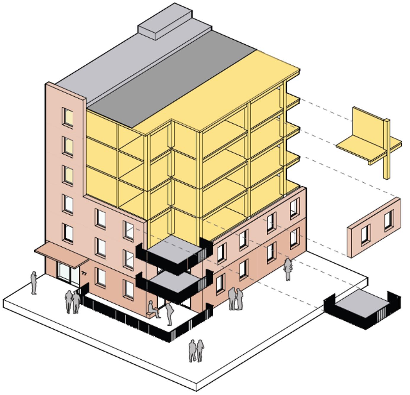
2 – Outline description of the system
The New Model Building approach is based on a multi storey multi occupancy residential building constructed from mass Timber with a concrete, Cross laminated timber (CLT) or Steel stability core around the stairs and lifts.
The system only addresses above ground structure and as such does not assume any specific foundation or basement conditions, but it does assume these are designed in compliance with the building regulations, NHBC guidance and the appropriate Eurocode design standards. It also assumes that they are of non-combustible structural materials.
3 – Applicability
The system/approach for the New Model Building is only applicable to buildings that meet the following criteria:
Aspect
Applicability of the New Model Building Approach
Building Location England & Wales
Upper floor Use
Ground Floor Use
Basements / Podiums/ Under crofts
Multi occupancy residential
Multi occupancy residential, Retail, F&B, Plantrooms & Storage, Office
Not applicable – assumed alternative non-combustible construction for any below ground level elements
Consequence Class 1, 2A or 2B (not Class 3)
Page 1 of 5
Building Height
Fire protection Strategy
Maximum Fire period
<18m to last occupied level
Full encapsulation by plasterboard or other fire-resistant system
60 Minutes
Visually Exposed Timber Not applicable
Service Class (BS EN 1995) 1 only
4 - Codes of Practice and Design Standards
The NMB approach assumes the design is carried out in accordance with the following design codes and standards:
• Building Regulations (England) Approved Document Part A
• Building Regulations (England) Approved Document Part B
• BS EN 1990: (Eurocode 0) Basis of structural design - UK National Annexe
• BS EN 1991: (Eurocode 1) Actions on structures - UK National Annexe
• BSEN 1992: (Eurocode 2) Design of concrete structures - UK National Annexe
• BS EN 1993: (Eurocode 3) Design of steel structures - UK National Annexe
• BS EN 1995: (Eurocode 5) Design of timber structures - UK National Annexe
• NHBC Standards and Technical Requirements Chapter 2.1 sections R3 (materials) and R5 (competent designer)
• All relevant NHBC technical guidance notes in particular:
o TG: 6.2/01 – socket outlet fire barriers
o TG: 6.2/03 – ventilation of cavities
o TG: 6.2/01 – external timber framed walls, movement gaps at eaves and verges
o TG No: 6.3/03 - DPCs under timber soleplates to internal partitions
5 - Design Approach
The New Model building is based on the following design approach for the primary structure:
• Simply supported timber floors spanning between vertical supports
• Downstand beams may be required to support high perfimeter or interior loads
• Column/Walls supported directly on appropriately designed foundations
•
• Vertical support formed of timbr walls or timber beam elements supported on timber or steel columns
• Column/Walls supported directly on appropriately designed foundations
• Concrete ground bearing or suspended ground floor slab
• Façade is non structural
• Lateral loads on facades transferred by overall diaphragm action of the floors to stability elements
• Vertical loads from façades and associated support systesm resisted at each floor level, bottom supported and restrained by the slab over at the head
• Lateral Stability system comprises lateral load resisting construction around the cores
BURO HAPPOLD Page 2 of 5
6 - Structural Components
The New Model Building approach is based on the following primary structural components :
Aspect
Floors
Superstructure
Podiums
Roofs
Stability system
Stair
Façade
Balconies
Parapet walls
Terraces
Canopy Roof
Applicable Structural Systems
Cross laminated timber slabs apart from under bathrooms/utility rooms where a joisted and decked solution is acceptable (in order to allow water leaks to be more easily detected.
Cross laminated timber walls, Glue-laminated timber beams and Gluelaminated columns or combinations of these
Steel beams and columns may be used if but should be encapsulated for fire protection rather than using intumescent paint
Assumed to be from non combustible material (.e.g steel, concrete masonry etc)
Cross laminated Timber (laid to fall) or timber joists/sheathing
Concrete, Cross Laminated Timber or Braced steel stability core incorporating the vertical circulation for the building
Timber, steel or concrete to the designers preference
Lightweight (not precast concrete or solid masonry), non structural facades supported at every level
Balconies of non comustible construction can be used and included in the design allowance
Roof level Parapet Wall can be included if required and included in the design allowance
No specific assumption has been made regarding terraces but these can be incoprotsare if they do not change the overall compliance and princaples of the NMB
Canopy Roof of non combustiable consturciton cane be used but need to included in the design allowance
BURO HAPPOLD Page 3 of 5
Visually Exposed Timber Not applicable, all timber to be encapsulated
Combustible Materials within the façade No – All structural timber elements (Floors, beams, walls, columns etc) are to be kept inboard of the full façade build up including any wall linings.
Materials specification
Timber elements used to be in accordance with relevant BS standard as follows:
• Glulam in accordance with BS EN 14080:2013
• Solid section timber to be in accordance with BS EN 14081:2016
• OSB to be in accordance with BS EN 300:2006
• Plywood to be in accordance with BS EN 636:2012
• LVL to be in accordance with BS EN 14374:2004
• Cross laminated timber in accordance with BS EN 16351:2021
All timber to be sustainability sourced timber to FSC/PEFC or other globally recognised responsible sourcing accreditation
Permanent and Variable Loading
The NMB approach has been developed on the basis of loadings and their combinations being as defined in the UK NA to BS EN 1990 and BS EN 1991
The approach is applicable to any wind, snow and live loadings as defined in these codes provided the structure sizing it done to suitability resist these loads.
Serviceability Limits
The NMB approach has been developed on the basis that serviceability limits as defined in the UK NA to BS EN 1995 for the timber elements and BS EN 1993 for the concrete elements and generally meet NHBC Standards requirements, whichever is more onerous
Vibration fo floors should be assessed and designed out in accordance with UK NA to BS EN 1995.
Detailing, Durability, Structural Integrity and Robustness
The NMB approach has been developed based on the following assumptions on detailing:
• All timber elements are kept within a Service Class 1 environmental throughout their life (Dry and heated)
• No external timber or timbers at risk of wetting (service class 2 or 3)
• All ground floor perimeter timber walls/columns to be stopped minimum 150mm above external ground level
BURO HAPPOLD Page 4 of 5
• All internal timber walls and columns to separate from the supporting slab/foundation with an appropriate DPC layer in accordance with NHBC TG No: 6.3/03
• The timber structure should be designed and detailed to provide sufficient robustness against disproportionate collapse in accordance with the Building Regulations Part A
Specification, Accuracy and Tolerances
The timber structure tolerances (both fabrication and erection) and general overall design and performance should be in accordance with the current version of the National Structural Timber Specification, BS 5606:2022 and the BS 8000 series
BURO HAPPOLD Page 5 of 5
NEW MODEL BUILDING FIRE PHILOSOPHY MANUAL
Fire Strategy Report
 WAUGH THISTLETON MODEL CLT BUILDING
JOSE TORERO, MICHAEL WOODROW, RYAN COLLINS AND WILHEM AQUINO
WAUGH THISTLETON MODEL CLT BUILDING
JOSE TORERO, MICHAEL WOODROW, RYAN COLLINS AND WILHEM AQUINO
1 Contents Introduction 2 0.1 Regulations 2 0.2 Definitions & abbreviations 2 0.3 Building description 3 0.4 Objectives of this analysis 4 1 Means of Warning and Escape 6 1.0 Requirement B1 6 1.1 Required Safe Egress Time (RSET) 7 1.2 Available Safe Egress Time (ASET) 9 1.3 Analysis & Discussion 12 2 Internal Fire Spread (Linings) 13 2.0 Internal Fire Spread 13 3 Internal Fire Spread (Structure) 14 3.0 Structural Fire Resistance 14 3.1 One-Dimensional Heat Transfer Modelling 14 4 External Fire Spread 17 4 0 External Fire Spread 17 5 Access and Facilities for the Fire Service 18 5.0 Fire Fighting 18 © UCL 2022 This document has been prepared for the sole benefit of Waugh Thistleton, for the purposes set out in the report. It is not intended for, and should not be relied upon by, any third party. No liability or responsibility is assumed for the use of this report, in whole or in part, by any third party.
Introduction
0 . 1 Regulations
Scope
The following fire report follows the UK Building Regulations; and therefore, defines the components of the building’s design that pertain to life safety. This report does not present a quantitative damage analysis, therefore property protection is not considered explicitly. Nevertheless, some general comments on the expected damage are provided when appropriate.
This document does not include a Fire Safety Management and Emergency Plan. A fire safety management plan details the arrangements to implement, control, monitor and review fire safety standards and to ensure those standards are maintained under Article 11 of the Regulatory Reform (Fire Safety) Order 2005. It must be produced by the responsible person but should be fully aligned with the UCL Fire Report.
Regulations & British Standards
The following documents have been used on the project:
Approved Document B - Fire Safety: Volume 2 - Buildings other than dwellinghouses
Approved Document J - Combustion appliances and fuel storage systems
Approved Document M - Access to and use of buildings
BS 9999:2008 Code of practice for fire safety in the design, management and use of buildings CDM Regulations
Introduction
0 . 2 Definitions & abbreviations
CLT
Cross Laminated Timber
Design fire
The ‘worst-case’ fire for which all systems are designed. Fire size is usually given in megawatts (MW)the energy released per second.
Egress/escape route
The path taken by occupants during a fire evacuation.
Fire compartment
A space within a building that is separated from the rest of the structure by fire-resistant barriers (walls, doors, floors, ceilings etc.)
Fuel load
Combustible material in a buildi ng.
Movement time
The time taken for occupants to travel from their location in the building to a place of safety.
Pre-movement time
The time between an alarm sounding and occupant movement towards an exit.
2
Introduction
0 .3 Building description
The Waugh Thistleton Model CLT building is arranged over several stories and is less than 18m in height. The building has been classified as “Residential” and is to include several self-contained residential flats. When analysing fire safety for residential flats, it must be assumed that some occupants may have limited mobility, be asleep and/or unfamiliar with the building and therefore may be slow or not able to evacuate during an emergency.
3
Introduction
0 . 4 Objective s of this analysis
The building discussed in this report is a worked example following the New Model Building (NMB) philosophy that has been designed to comply with building regulations following the most simple and linear approach. Provisions that exceed those established by guidance are included for the purpose of robustness.
Should a building be designed according to the New Model Building philosophy, but with a noncombustible struct ure , th e building would be deemed to satisfy all building regulation requirements. Th erefore , the objective of this analysis is to demonstrate that the use of structural timber does not introduce any additional risk to occupants .
It is therefore essential for this analysis to show that the properties and behaviour of timber does not affect the nature and characteristi cs of any potentisal fires in the building as well as the role that the structure shall perform in the event of a fire. The role that a structure shall perform in the event of a fire is defined by building regulations. In this case, the primary building regulation s that need to be satisfied are Regulations B 1 - B 5 , which pertain to fire safety.
Approved Document B requires compliance with five functional requirement and therefore, a timber building needs to deliver a level of performance that is equal or better to that of a structure designed using non - combustible materials (see extract above) .
The approach to be followed is a conservative one where protection to the timber (encapsulation) is designed to prevent the pyrolysis/ignition of the structural timber. This is done with two objectives, first to allow for the structural timber to be treated as non - combustible and second to minimize potential damage. In the event of a fire only the protection will be damaged.
Below, a brief description of the detailed objectives set for this building and how it will be demonstrated that the design proposed guarantees that the presence of timber as a structural material will not increase the risk.
B1 Means of Warning and Escape: The presence of structural timber can alter the course of the fire, therefore, it can affect detection and compromise means of escape. Furthermore, for egress
strategies such as ‘staged evacuation’ or ‘stay - put’ the structure must support and enable the strategy. Means of escape, detection and alarm systems, compartmentation and structural behaviour have an impact on the safety of occupants. The basic premise behind the egress strategy is compliance with the guidance of Appr oved Document B. Additionally, the following assessment has been conducted to establish the adequacy of the design in regard to the use of timber as a structural material:
a) Structural timber will not ignite before egress from the unit where the fire originated has been completed. If everyone can be demonstrated to have evacuated this unit before the timber ignites, then the evolution of fire growth , while occupants remain in the unit of fire origin, will be identical to a non- combustible building.
b) Structural timber will not ignite until detection, alarm, sprinklers and other means of protection devoted to life safety have successfully perform their functions. If that is the case the performance of these systems will be identical to their performance in a buil ding constructed from non- combustible materials.
c) The timber structure will be encapsulated in a manner that pyrolysis will not start through the duration of a fire fuelled by the building furnishings. A conservative fuel load, and ventilation scenarios, wi ll be used to calculate the duration and characteristics (temperature, heat fluxes) of worst- case fire scenarios. This fire scenarios will then be used to demonstrate that burn - out of the fire will occur before the onset of pyrolysis of the encapsulated st ructural timber. It is assumed that all structural timber is encapsulated.
d) The temperature increase of the structural timber will not affect compartmentation, thus not changing the egress strategy normally applied to a building with a non- combustible structure, the viability of means of egress and not altering the available egres s times (ASET). Compartmentation will be guaranteed as required by Approved Document B internally and externally.
B2 Internal Fire Spread (linings): Again, t he presence of structural timber can alter the course of the fire. Building regulations assume fir e growth rates that are consistent with what is normally expected from an occupancy. In this case a residential occupancy. The following assessment has been conducted to establish the adequacy of the design:
e) The timber structure will be encapsulated in a m anner that pyrolysis will not start through the duration of a fire fuelled by the building furnishings. Therefore, it will be demonstrated that the structural timber will never intervene in a fire. A conservative fuel load, and ventilation scenarios, will be used to calculate the duration and characteristics (temperature, heat fluxes) of worst- case fire scenarios. This fire scenarios will then be used to demonstrate that burn - out of the fire will occur before the onset of pyrolysis of the encapsulated struc tural timber. It is assumed that all structural timber is encapsulated.
B3 Internal Fire Spread (Structure): A structure is required to fulfil its functions (stability and compartmentation) until burn- out of the fire. This defines fire resistance requirem ents for any structure. The timber structure of this building will therefore satisfy fire resistance requirements as established by guidance in Approved Document B. In addition:
a. The timber structure will be encapsulated in a manner that pyrolysis will not start through the duration of a fire fuelled by the building furnishings. Therefore, it will be demonstrated that the structural timber will never intervene in a fire. A conservative fuel load, and ventilation scenarios, will be used to calculate the durat ion and characteristics (temperature, heat fluxes) of worst- case fire scenarios. Th ese fire scenarios will then be used to
4
Extract
– Approved Document B (2019) Volume 2, Section 0
demonstrate that burn- out of the fire will occur before the onset of pyrolysis of the encapsulated structural timber. It is assumed that all structural timber is encapsulated.
B4 External Fire Spread: All elements of the timber structure will be encapsulated in a manner that no timber will be exposed as part of the external building envelope. Furthermore, detailing of the façade system has been analysed in detail to guarantee that the solutions required to adequately resist external fire spread will provide additional robustness. Given the importance of guaranteeing compartmentation, and the potential consequences of failing to deliver a single unit fire, special emphasis has been given to this analysis to the robustness of the solutions. The objective is to provide a higher - level guarantee that the fire will not breach external compartmentation.
B5 Access and Facilities for the Fire Service: Access and facilities for the fire service will strictly follow guidance in Approved Document B. Furthermore, it is recognized in the design that fire brigades are most effective when addressing a single unit fire, therefore, special emphasis has been given to the analysis of the façade detailing, it is expected to add to the robustness of the solutions. The objective is to provide a higher - level guarantee that the fire will not breach external compartmentation.
5
1. Means of Warning and Es cape
1 . 0 Requirement B1
Egress is the primary component of the fire strategy for the Model CLT Building The objective of this section of the report is to demonstrate that the timber structure has no impact on the evacuation of the escaping occupants.
Egress is a multifaceted event in which people and their responses are sensitive to the incident scenario, information available and the local conditions (Gwynne and Rosenbaum, 2016).
The approach applied within this report is a simplified model that makes use of previous investigations and prescriptive codes, employing empirical data gathered from a variety of studies carried out over a large period of time. This has been conducted with the hope of accounting for the large variations and uncertainties inherent in engineering data, previously mentioned.
The principle is as follows – the time taken for occupants to evacuate must be less than the time taken to reach untenable conditions within the building. These two times are known as the Required Safe Egress Time (RSET) and the Available Safe Egress Time (ASET), respectively.
6
1. Means of Warning and Escape
1 . 1 Required Safe Egress Time ( RSET )
1.1.1 Context
To develop the Required Safe Time for Egress (RSET), it is logical to account for the worst-case scenario, given that the model accounting for the growth and development of the fire also utilises a worst-case scenario approach. Therefore, in the context of the Waugh Thistleton model residential building, the greatest value of RSET will be produced for an occupant on the uppermost floor, at a distance greatest from the central evacuation stairwell. This in indicated in Figures 5 and 6.
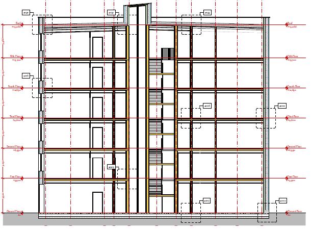
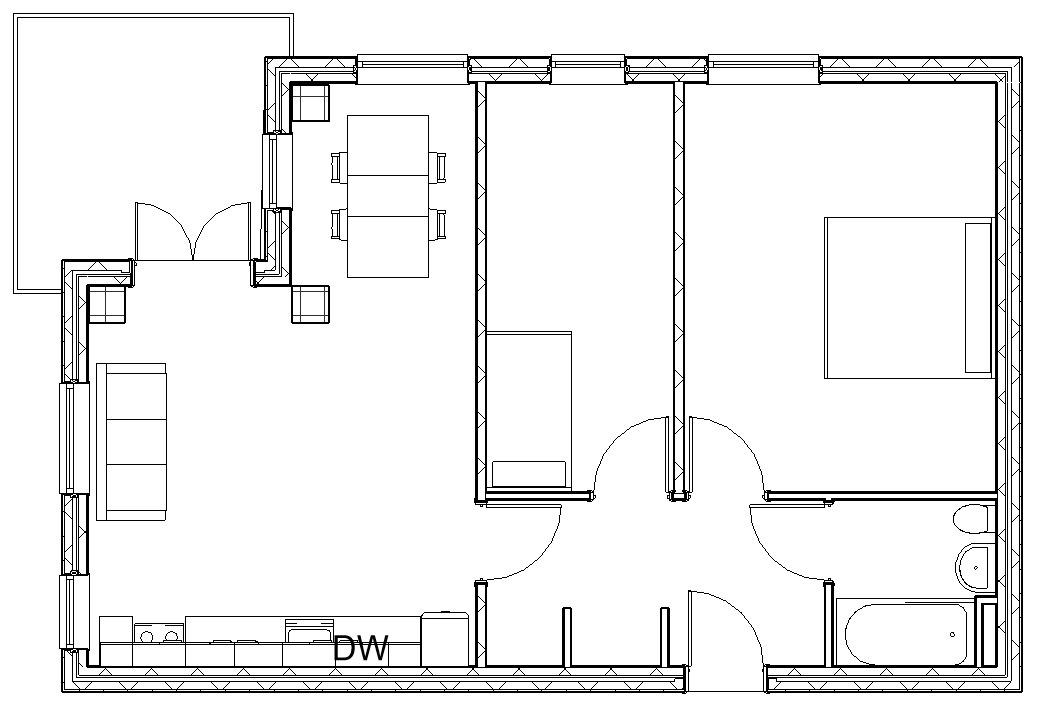
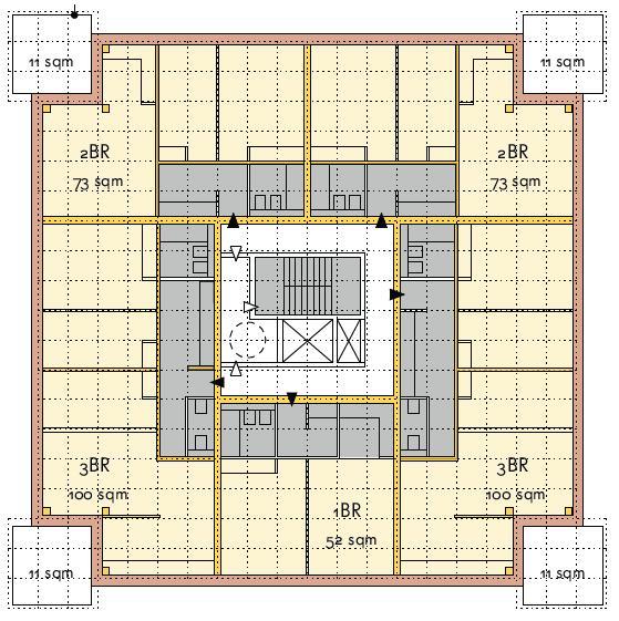

It can be seen from Figure 5 that the top floor is six storeys above the ground floor. For the specific compartment that is being investigated, highlighted in Figure 6, the greatest distance from the furthest point within this compartment to the central stairwell can therefore be investigated further.
Figure 7 highlights the furthest distance within the compartment to the exit. This point is considered because, even though the fire may not start at this specific point within the compartment, it is generally considered in the field of fire egress that a compartment will not possess internal compartmentation and fire resisting elements within, therefore the value of RSET is given for the entire compartment. Even though the fire growth and development has been investigated in the single, small bedroom, the furthest point for egress out of the compartment is still out on the balcony. The total distance from the compartment fire exit to the outlined location is 13.3 metres. Obviously, being the greatest distance does not absolutely imply that from this location, it will take the greatest amount of time to reach the exit, as a result, the assumptions made throughout this process are outlined at the end of this section.
1.1.2
Data Collection
The calculations for the RSET can be divided into multiple, distinct categories that can be easily computed separately. Equation 1 highlights these categories.
���� = �( + �* + �(,-. ) + �. (Eq. 1)
where:
- td = Time from ignition to detection
- tn = Time from detection to occupant notification of an evacuation situation
- t(p-e) = Time from notification until evacuation commences (pre-movement)
- te = Time from the start of purposive evacuation until safety is reached (movement)
1.1.3
Detection and Notification
Timely evacuation begins with the detection and notification of a fire hazard. Most modern alarms systems, particularly in buildings of residential occupancy, will be equipped with both smoke and heat alarms that will activate immediately at the detection of an emergency. As a result, and also for the simplicity of calculations, both td and tn, can be considered negligible in terms of the RSET.
7
Figure 7 - Furthest point and route from Fire Exit within compartment.
Figure 5 - Section of Waugh Thistleton Model
Figure 6 - Compartment of Interest for RSET calculations
1.1.4 Pre-Movement
The pre-movement times for calculating RSET is also another field of study that has raised concern. Premovement can be broken down further into the detection, decision, alarm and reaction of occupants to begin evacuation, however for this case, they have been grouped into a single pre-movement category.
Although common knowledge would suggest that strong cues such as the presence of smoke should trigger a quicker response compared to evacuation drills, results of fire investigations do not confirm this assumption (Averill et. al, 2005). Research has been gathered from numerous studies that have investigated pre-movement times and is presented in Figure 8. This data covers a wide range of studies, from different occupancies and scales, with the aim of providing a good basis to determine an average value that is representative for pre-movement times in this scenario.
The pre-movement time can be minimised by specifying an L1 category smoke detection system (BS 5839). This implies mounting a smoke detector in every occupiable room and a heat detector in every kitchen.
Tanaboriboon and Guyano, 1991 Tanaboriboon and Guyano, 1991 Seyfried, 2005 Damen and Hoogendoom, 2005 Klupfel, 2005 Schultz, Schulz and Fricke, 2008 Larusdottir and Dederichs, 2011
Literature Source
9 – Horizontal Movement Speeds gathered from various research studies and investigations
Shields,1998 PurserandBensilium,1999ShieldsandBoyce,2000ShieldsandBoyce,2000Frantzich,2001(1)Frantzich,2001(2)Frantzich,2001(3)Frantzich,2001(4)Gwynne,2007(1)Gwynne,2007(2)NIST,2008NilssonandFrantzich,2008NilssonandFrantzich,2008Purser,2008Gwynne,2009Sharma,2009
Figure 8 - Pre-Movement time gathered from various research studies and investigations
1.1.5 Horizontal Evacuation Speeds
The time taken post-movement to reaching a point of safety outside the building requires additional data for movement speeds during evacuation horizontally, as well as when traversing stairwells. As a result, a similar data collection process has been conducted for both, with the data presented in Figures 9 and 10
ProulxandBenichou,2007(1)ProulxandBenichou,2007(2)Peacock,AverillandKuligowski,…Peacock,AverillandKuligowski,…Kretz,2008(1)Kretz,2008(2)Kretz,2008(3)Hoskins,2011LarusdottirandDederichs,2011FujiyamaandTyler,2011Capote,2012(1)Capote,2012(2)Capote,2012(3)Kadokura,2012
Figure 10 - Stairwell Movement Speeds gathered from various research studies and investigations
1.1.7
This section presents the steps to calculating a value of RSET for the defined compartment by applying the literature averages for the defined variables.
The example calculations follow the steps for calculating RSET apply the average values obtained from literature. However, as mentioned in fire safety engineering, there is a great deal of uncertainty
8
1.1.6 Stairwell Evacuation Speeds
Calculations
0 20 40 60 80 100 120 140 160 180
PreMovement Time (seconds) Literature Source
0 0.2 0.4 0.6 0.8 1 1.2 1.4 1.6 1.8 2
Stairwell Walking Speed (metres/seconds) Literature Source 0.6 0.8 1 1.2 1.4 1.6 1.8
Figure
Walking Speed (metres/seconds)
Horizontal Plane
surrounding speeds of evacuees, coupled with the data being relatively sparse, values for best- and worst-case scenarios have been reproduced in the same method using maximum and minimum values. These breakdowns can be seen in Figure 15.
1. Means of Warning and Escape
1 . 2 Available Safe Egress Time ( A SET)
1.2.1 Background and Context
In order to determine if the occupants of the building have enough time to safely evacuate in the event of a fire. The objective is to create a design that ensures that the RSET is much shorter than the ASET. The following is a worst-case calculation of the ASET, which is the amount of time that is available to the occupants to evacuate before the fire creates untenable conditions within the building. However, it is important to first define what constitutes as ‘untenable’ for this model. For this structure, three critical stages have been selected in which, under normal circumstances, the building is no longer safe and poses a significant danger to life.
The first defined stage is the point of flashover in the room of fire ignition. When flashover occurs, the fire has reached temperatures at which almost all of the combustible materials within the enclosed area will immediately ignite, further contributing to the growth and prolonging of the fire. It is crucial that at this point, all occupants within the surrounding area – such as the compartment in question as well as the rest of the floor – have safely evacuated the building. It is important to note that this is a reference time and the objective is to have everyone evacuate much earlier than the time to flashover.
Once flashover has occurred, the fire will continue to burn at high temperatures until all fuel within the compartment has been consumed, where burnout is reached. The temperature of this fire is high, posing a threat to the gypsum that is encapsulating the structural timber, as well as the structural timber itself. The heat is able to be transferred through the gypsum and, if hot enough, ignition of the structural timber may occur. This is the second stage that has been selected. As it is vital that the structural timber does not begin to burn and threaten the structural integrity then, it will be required that this reference value shall be longer than the time to burnout.
Due to the nature of the structural timber, the glue which adheres the lamella together can be considered as its weakest constituent. If the heat is able to penetrate past the gypsum, through the depth of the first lamella, and into the first glue line, the adhesive properties of the glue will be lost. This can bring the first lamella and the plasterboard attached to it down, leaving the timber elements exposed. This is known as delamination. This is the third and final stage selected, at which point the structural timber will begin contributing to fuelling of the fire. If the timber delaminates it is not possible to guarantee that the fire will not lead to the complete destruction of the building.
This range of values also serves to provide a quantitative indication of potential geometrical variants of the residential units that will still satisfy egress requirements. The calculations presented here correspond to a specific configuration, but the approach and results can be applied to any other unit configuration.
It is recognized that this approach to performance assessment is extremely conservative because it ignores the containment benefits of the gypsum wall board, the insulating effect of charring and the self-extinction potential of timber. Nevertheless, it was considered as an adequate starting point for this analysis. As mentioned before, it also has the added advantage that it provides a guarantee that only the encapsulation will be damaged in the event of a fire. From the perspective of repair costs this could be a significant benefit.
9
45.94 27 80 10.39 9.37 11.6 5.16 4.65 5.79 50.98 38.3 65.37 10.7 9.65 12.02 0 20 40 60 80 100 120 140 160 180 200 Average RSET Time Minimum RSET Time Maximum RSET Time RSET from groundfloor stairwell to fire exit 10.7 9.65 12.02 RSET from top-level to groundfloor 50.98 38.3 65.37 RSET to top-level stairwell 5.16 4.65 5.79 RSET out of initial compartment 10.39 9.37 11.6 Pre-Movement Time 45.94 27 80 TIME (SECONDS)
Figure 15 - Comparison of Minimum, Average, and Maximum RSET.
1.2.2 Pre-Flashover Zone Model
This approach models the fire as a pre-flashover compartment fire where flaming ignition has already occurred. To achieve this, strong simplifications have been made, employing a zone model which divides the room into two distinct zones: an upper layer which is made up of hot combustion products (smoke), and a lower layer which is simply ‘cold’ air. This simplified zone model is a worst-case scenario that delivers the shortest possible ASET because it does not allow for any smoke to be lost.
From the source of the fire, the smoke rises to the ceiling where it accumulates over time. As more smoke is trapped, the smoke layer thickens and increases in temperature, simultaneously descending from the ceiling down to the floor. While this is happening, the fire itself is also growing in size, which is modelled as growing radially outwards. This is dependent on the material properties of the fuel being consumed, which influences the amount of energy that is released and also how quickly it burns and spreads the flames.
The model makes use of the ideal gas law and laws of conservation of mass and energy to determine the amount of smoke produce as well as its temperature. Although a simple approach, it models the worst-case scenario of the growth of the fire meaning that, if the RSET is found to be below the ASET calculated here, the building will be considered safe, since it keeps the occupants from danger even in the worst possible situation.
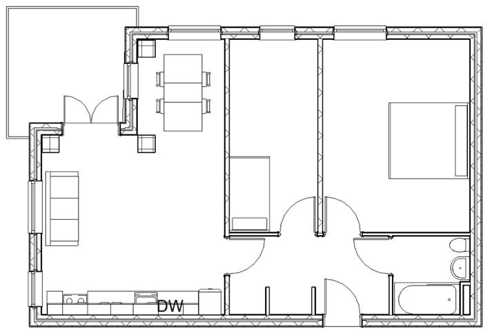
The dimensions of the room are given below:
Width, X0 = 2.1m
Length, Y0 = 4.6m
Height, H0 = 3.05m

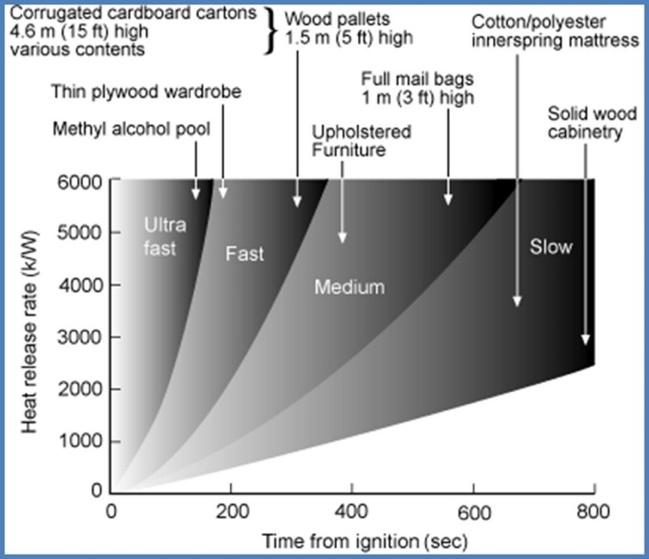
To model the worst-case scenario, the smallest and simplest room has been modelled as this is the most confined space in the flat, seen in Figure 16, which often results in the most dangerous conditions in a shorter amount of time. This is because the fire accumulates in a smaller floor (ceiling) area and can descend to the floor quicker. Because of this, if it is found that the RSET does not exceed the ASET in this room, it may mean that other rooms may not have to be investigated as they would have less dangerous conditions. This particular room is a bedroom, so it has been assumed to contain items that would usually be expected to be found in a bedroom, such as wooden furniture and a carpeted floor. As mentioned previously, the type of fuel that is available to the fire will influence the rate of its growth and the energy it. This is based on the material properties of the fuel, and the variables are its:
- DHc : Energy Released per Kilogram of Fuel Burnt
ṁ’’F : Burning Rate per Square Metre
- Vs : Flame Spread Velocity
These three variables are grouped together into a single variable, a (alpha), and values for alpha can be obtained based on data gathered in literature. Using Figure 17, the contents of the room being modelled would mean that it would place in either the ‘Slow’ or ‘Medium’ category, with an a of 0.0029 and 0.0117 from Table 1 respectively. As it is unknown which category would create the worstcase scenario, both will be modelled and the fire that reaches flashover the fastest will be used for the ASET, as well as for the subsequent stages.
Figure 18 - Evolution of the Compartment Fire showing the Temperature and Height of the Smoke Layer Calculations were also conducted for a ceiling height of 2.3m, showing that there was no significant difference in results.
10
-
273.00 323.00 373.00 423.00 473.00 523.00 573.00 0 0.5 1 1.5 2 2.5 3 0.00 50.00 100.00
(0.0117) Temperature (0.0029) Temperature [K] H [m] time [s]
Height (0.0117) Height (0.0029) Temperature
Figure 17 - Heat Release Rate Categories dependent on Room Occupancy.
Figure 16 - Room of Interest for ASET Calculations with Dimensions
Table 1 - Classification of Alpha Values.
Another factor that must be modelled is the leakage of smoke out of the room as the fire progresses. Openings within the room, such as the window (if open) and gaps around the edge of the door will allow this to occur. This will affect the time to flashover, so three scenarios have been modelled where there is 0%, 10%, and 20% leakage, with each value representing the percentage of volume of smoke lost due to leakage. This analysis was conducted only to establish the sensitivity to this process. The analysis showed that adding the leakage always increases the time to flashover, therefore, again, the only worst-case scenario will be used (i.e. no leakage).
The graph in Figure 18 shows an example compartment fire evolution, displaying how the temperature and height of the smoke layer varies over time. For this, an alpha of 0.0029 (Slow) and 0.0117 (Medium) been used, with 0% leakage. It shows that the time to flashover will vary from 90 sec (Slow) to 140 sec (Medium).
The graph shows that as the smoke layer as reached the floor, and the fire will have reached temperatures above approximately 420-430K (i.e. 147-157 oC). Above these temperatures the increase is very fast and therefore flashover can be assumed to occur.
It is important to note that in relatively small rooms with no leakage (which implies no ventilation), oxygen levels within the room can quickly become depleted. This would mean that the fire may never actually reach flashover and begin to decay (STA, 2017). However, it is not certain whether this will occur, so the ASET calculated will still be used.
1.2.3 Post-Flashover – Ventilation Factor
Once the fire has reached flashover, it will continue to burn at high temperatures until it has consumed all sources of fuel in the room, at which point the fire will begin to decay. It is during this period where the structural timber is most at threat from the fire, as it is at very high temperatures for a prolonged duration. The purpose of modelling this period is to find the temperature at which the fire burns at, the rate of fuel consumption, and by extension, the duration the fire will burn for until it decays.
The simplified formulation used here is known as The Compartment Fire. This formulation allowed for the maximum temperature the fire could burn at to be determined and for this model, it is assumed that the fire will burn at this temperature for the entire duration. This approach is justified by that fact that the solution to the full energy equation would provide levels of precision that are simply not necessary, as well achieving the recurring goal of determining the worst-case scenario.
Experimental work by Thomas & Heselden (1972) consisted of over 400 experiments, producing realistic scale compartment fires (approximately 4m x 4m x 4m). The effect of scale on the experiments
were found to be minor, so smaller scale compartments were used, but similarities to the Waugh Thistleton room provides an added benefit. Through a combination of empirical data and theoretical consideration, the experiments established relationships between the maximum temperature, burning rate, and the geometry of the compartment. Ultimately, these values were found to be based on a single parameter, known as the Ventilation Factor, shown below.
0 01 231 (Eq. 2)
where:
- A - Surface area of the room excluding floor and any openings.
- A0 - Area of all openings
- H0 - Average height of all openings.
These variables are also used to calculation the Fuel Consumption Rate, shown below.
� = 0 1�8 2�8 (Eq. 3)
This allows the determination of the Time to Burnout, which time in which the fire will have consumed all sources of fuel in the room, where it will begin to decay.
As it is unknown whether the door will be open or not, there will be two sets of calculations modelling the door as an opening and another where it is not considered an opening. The presence of an additional opening will mean that there is more available oxygen for the fire to burn at a higher temperature. However, this reduces the total duration it burns for as it will consume the fuel faster.
The difference between Case 1 and Case 2 can clearly be seen, where a 20% increase in temperature results in a 260% increase in fuel consumption rate. In this situation, as the temperature in Case 2 is not much lower than Case 1, the extended burning period expected from Case 2 is a greater threat to the structural timber, as the fire has more time to transfer the heat through the plasterboard and into the timber.
1.2.4 Post-Flashover – Time to Burnout
�:; = <= > (Eq. 4)
where:
- Mf – Mass of Available Fuel Within the Room (kg)
- tBO – Time to Burnout (s)
- R – Fuel Consumption Rate
For Mf, two values have been selected for the analyses. Firstly, a lower bound estimated from studies by Pettersson, O et al. (1976) for a hotel room statistically representative of Swedish conditions shown
11
Class a Slow 0.0029 Medium 0.0117 Fast 0.0469 Ultra-Fast 0.1876
in Figure 20. By adding the masses of the contents selected in the table, a lower bound value for mass of 184kg is obtained.
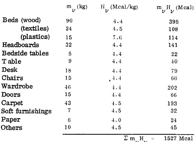
Figure 20 - Mass of Available Fuel within a typical Swedish hotel (Pettersson, O et al., 1976)
Secondly, an upper bound value derived from EN 1991-1-2, which gives the fire load density for a dwelling as 780MJ/m2. Multiplying this value by the dimensions of the room (2.1m x 4.6m), dividing by the calorific value of timber (18.41MJ/kg) obtains a mass of 409.28kg.
Table 2 – Times of Burnout and Temperatures based on Various Conditions
1. Means of Warning and Escape
1 . 3 Analysis and Discussion
To interpret the results, comparisons between the values of ASET and RSET must be understood. As defined, the first ASET time, being the time taken for the specific compartment to reach untenable conditions, is approximately 90 seconds for the worst-case scenario. Figure 15, displaying values of RSET, shows that the maximum pre-movement time combined with time taken to leave the compartment is 91.6 seconds. In this instance it can therefore be said that the growth of the fire is so rapid that it may pose an immediate threat to those within the specific compartment. Nevertheless, it is important to note that when using those estimates for the pre-movement time, a building with a structure made of non-combustible materials will give exactly the same result. It is therefore clear that the worst case scenario of the pre-movement time is excessive.
Therefore, despite the proximity between RSET and ASET, it will be consider that if the structural timber does not ignite that the occupants can escape the compartment and continue the evacuation process. The second necessary comparison is that of the time taken for the ignition of the structural timber element.
Structural timber can be made up of a variety of wood species, typically spruce of pine boards which are both soft woods, of which the ignition temperatures can vary. As a result, data has been collected for softwoods of comparable properties, seen in Table 4.
Table 3 - Failure (Ignition) Temperatures of Structural Timber
Ignition Temperature of Timber (°C)
Source Temperature (°C)
Janssens, 1991
Janssens, 1991
Janssens, 1991
As expected, Table 2 shows that using Case 2 where the fuel burns slightly less intensely and consumes fuel slower paired with an abundance of fuel, the fire burns for much longer while still sustaining a high temperature.
With this, the next stage of the analyses can be carried out, as the total duration and the maximum temperature have been obtained. The time calculated here does not provide a value for the ASET, as it must first be determined whether the situations proposed in Section A.2.1 will occur; the ignition and degradation of the structural timber, and the failure of the glue lines within it.
Wood Specimen
354 Western Red Cedar
349 Radiata Pine
350 Douglas Fir Yudong and Drysdale, 1992
364 Obeche Yudong and Drysdale, 1992
Shi and Chew, 2021
Shi and Chew, 2021
Mikkola and Wichman, 1989
Mikkola and Wichman, 1989
Quintiere and Harkleroad, 1985
Quintiere and Harkleroad, 1985
375 White Pine
380 Chinese Scholar Tree
383 Douglas Fir
275 Rimu
281 Radiata Pine
376 Rimu
376 Radiata Pine
Average 351.189
Figures 21 & 22, show that at 2400 sec the first structural timber node displays a maximum temperature of approximately 219°C. Comparing this value to the average temperature seen from Table 4, 351°C, it can be concluded that the structural timber does not reach temperatures high enough to ignite and begin charring. Table 2 shows that the longest burnout time is approximately 2,400 sec and as a result, this second defined ASET stage is effectively an infinite value as the fire will burnout before reaching ignition temperatures, meaning the value of RSET will always be less, and therefore safe.
12
Lower Bound Fuel Time Upper Bound Fuel Time Temperature Open Door 06:56 15:26 1009.09°C Closed Door 18:02 40:06 841.81°C
The third and final defined ASET stage is that of the time taken for delamination to occur at the first structural timber lamella, exposing the structural timber to greater temperatures and ultimately greater degradation in strength. Figure 26 also shows that, at 60mm depth, the maximum temperature reached by the first CLT lamella is 32.49°C. This is below the onset of glass-transition temperatures of the adhesives (>40°C) Furthermore, loss of bonding leading to delamination has been reported as high as 300°C (Johansson and Svenningsson, 2018; Brandon and Dagenais, 2018). Therefore, this final ASET can also be deemed safe.
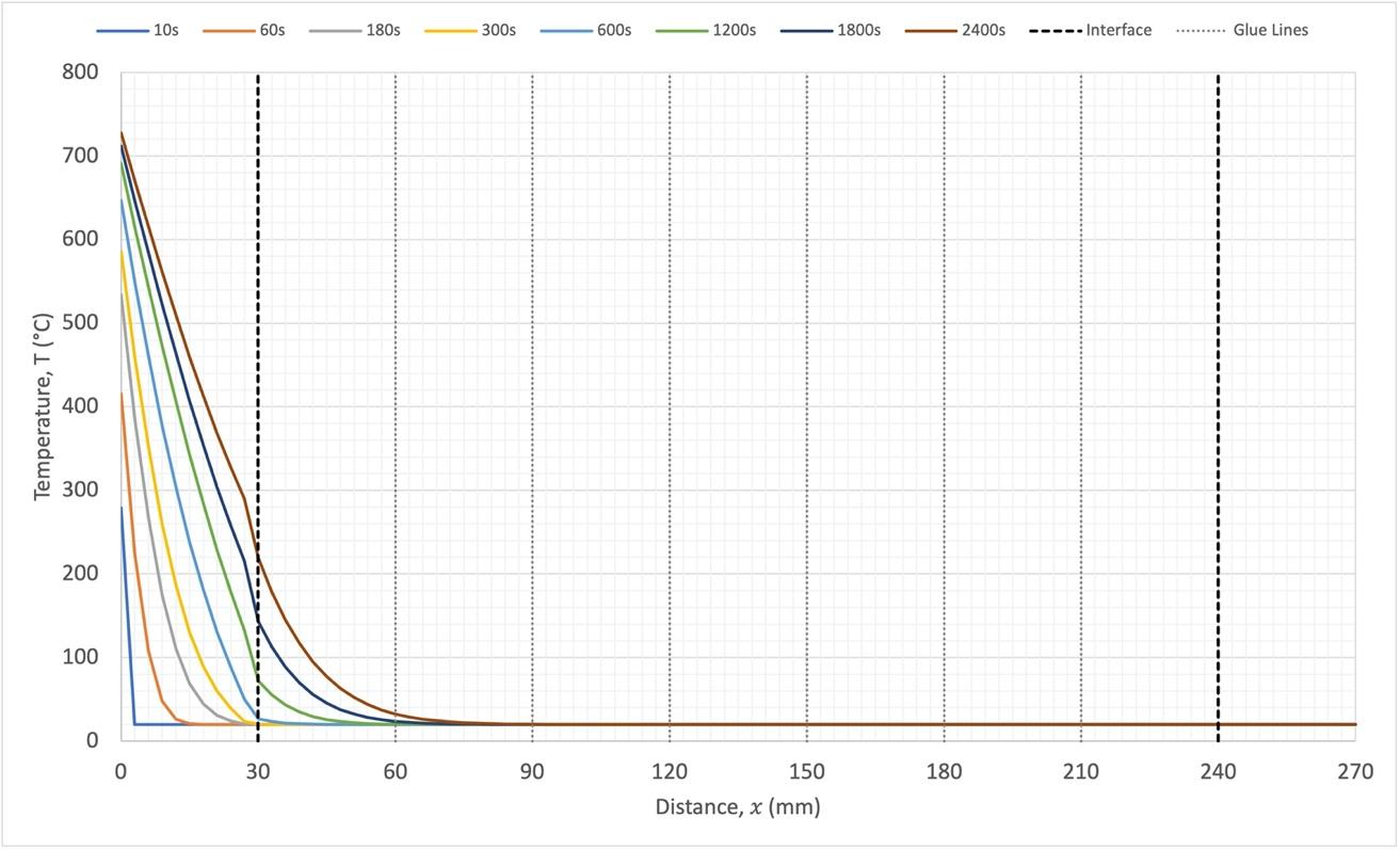
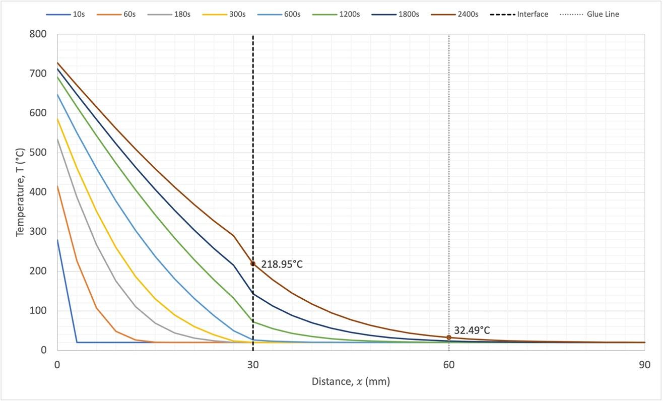
2. Internal Fire Spread (Linings)
2 . 0 Internal Fire Spread
2.0.1 Overview
The building is divided into fire compartments to limit the spread of fire throughout the building. Each floor slab provides compartmentation to limit the spread of fire and smoke vertically. Fire-rated walls and doors provide compartmentation to limit fire and smoke spread horizontally.
2.0.2
Insulation
The building requires thermal insulation in the facade and roof build -up. The insulation in the facade should be non-combustible. The insulation in the roof should either be non-combustible or fully encapsulated.
2.0.3 Contents
The contents of the building are assumed to be typical of a residential building, including soft furnishings and electrical appliances. The building is not designed to contain high hazard contents (e.g., flammable liquids or gases).
Furniture and appliances within the building should be individually certified to the relevant European standards for fire safety.
2.0.4
Insurance
The strategy is to contain fire and smoke to the compartment of fire origin. It is assumed that the contents of the room and the interior finishes may be damaged during a fire and may need to be replaced. It is also assumed that there may be superficial damage to the façade on the level immediately above the fire. The building is to be designed to ensure that this is the extent of the damage caused by a single, accidental fire in the building.
13
Figure 21 - Results from One-Dimensional Heat Transfer Model
Figure 22 - Zoomed in Profile of One-Dimensional Heat Transfer Model Results
Gypsum-Timber Interface
Gypsum-Timber Interface
Gypsum-Timber Interface Interface between 1st and 2nd Lamella
3. Internal Fire Spread (Structure)
3.0 Structural Fire Resistance
3.0.1 Methodology
A structure is required to fulfil its functions (stability and compartmentation) until burn-out of the fire. This defines fire resistance requirements for any structure. The timber structure of this building will therefore be designed to satisfy fire resistance requirements as established by guidance in Approved Document B.
In addition, the timber structure will be encapsulated in a manner that will protect it from a fire involving the building furnishings. The following analysis will demonstrate that the structural timber will never become involved in a fire.
A conservative fuel load and ventilation scenarios will be used to calculate the duration and characteristics (temperature, heat fluxes) of the worst-case fire scenarios. These fire scenarios will then be used to demonstrate that burn-out of the fire will occur before the onset of pyrolysis of the encapsulated structural timber.
3.0.2 Construction Site Safety
The above analysis assumes that all structural timber is fully encapsulated. During the construction phase however, there will be a period following installation where the timber structure will be exposed. During this period, the strategy of encapsulation cannot be relied upon, and the above analysis will not be valid.
The ultimate responsibility for site safety lies with the C ontractor. The following points should be considered as part of a managed strategy developed by the Contractor to mitigate the risk posed by structural t imber on site :
- Minimise the storage of combustible materials
- Install a fire detection and alarm system
- Install onsite security cameras
3. Internal Fire Spread (Structure)
3.1 One - Dimensional Heat Transfer Modelling
3.1.1 Context
The previous section has explored the developmental stages of fire growth, from ignition, flashover and through to burnout scenarios. This section builds upon the values, both times and temperatures of the different fire scenarios previously discussed.
As outlined previously, the room of interest with regards to the fire location is that seen in Figure 23; within the same compartment considered when discussing evacuation times. More specifically, to conduct a One-Dimensional heat transfer model, a singular structural element needs to be identified to assess the propagation of heat throughout the structure over the development of the fire. Figure 24 highlights the wall element chosen for investigation.
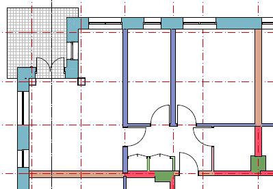
Figures 23 and 24 – Room (left) and Wall Element (right) of interest for One-Dimensional Heat Transfer
A One-Dimensional Heat Transfer model is a simplified approach to investigating the heat flow through an object by exclusively observing the flow through the cross-section of the object, where there is not heat flow laterally out the sides of the object. As a result, the temperature throughout the crosssection of the object is exclusively a function of one-dimension, and the properties of the material medium. In this instance, the object in question is the wall defined in Figure 24, which has been designed to the appropriate regulations by Waugh Thistleton and possesses the fabric-build up as seen below in Figure 25.
Wall Type: NMB – IW-02-A
Fire Performance: 60 Minutes REI
Composition (left to right):

- Skim and Paint (3mm)
- Wall Lining Board (15mm)
- Wall Lining Board (15mm)
- CLT Wall Panels (210mm)
- Wall Lining Board (15mm)
- Wall Lining Board (15mm)
- Skim and Paint (3mm)
Figure 25 - Fabric Build Up with Dimensions of Wall Element
14
3.2.2 Modelling Approach
The modelling approach assumed is centred around a discretised version of the fundamental heat transfer equation for that in two dimensions. Equation 5 highlights the two-dimensional heat transfer equation for transient conditions with materials of constant properties, where there is no internal heat flux generation.
? @ AB AC = AD B AE D + AD B AF D (Eq. 5)
This equation can be then further simplified to be applied to one dimensional application, such as those used in this approach, by applying central-difference approximations by designating discrete nodal points within the element of interest through locations of x and y coordinates. All the equations applied in the modelling methodology, however, are all derived from Equation X, following the fundamental principle that the energy into a discretised node must be equal to the output of energy plus the energy absorbed by the material represented by that node. The equations below are those which have been applied at various points throughout the cross-section highlighted in Figure 26.
Outer Boundary/First Gypsum Node:
THIJ? = KL∆N OPQRSTU VPQRSTU ∆W XTY TH I [ + K\PQRSTU ∆N ∆WD XTHJ? I TH I [ + TH I (Eq. 6)
Internal Gypsum Nodes:
Final Gypsum Node:
THIJ? = Fo_`IabH XTHJ? I TH-? I [ + (1 2Fo_`IabH )TH I (Eq. 7)
THIJ? = TH I \PQRSTU ∆WD XTH I TH-? I [ + defg ∆WD XOPQRSTU VPQRSTU [ (THJ? I TH I ) (Eq. 8)
First CLT Node:
Internal CLT Nodes:
THIJ? = TH I dPQRSTU ∆WD (Oefg Vefg ) XTH I TH-? I [ + \efg ∆WD (THJ? I TH I ) (Eq. 9)
THIJ? = Fohij XTHJ? I TH-? I [ + (1 2Fohij )TH I (Eq. 10)
The superscripts of p and p+1 indicate the time dependence of T, where the temperature is expressed in terms of the new (p+1) time and previous (p) times. The subscripts of (m) and (m+1) denote the location of the temperature node, with ���J� indicating the temperature at the following time stamp at the same location. As a result, the calculations must be performed sequentially for each node, at increasing time intervals of ∆� . For this reason, this model approach is a forward propagating centraldifference approximation.
Equations 6-10 are explicit, meaning that all the unknown nodal temperatures at t(p+1) are determined exclusively by applying the known nodal temperatures at t(p). In this way, the distribution of temperature throughout the depth of the cross-section is obtained by running the model for a defined period of time, using intervals of ∆� . It must also be noted, that when running the model, it was found that the temperature fell to the residual ambient temperature much before the returning boundary from timber back to gypsum. As a result, these boundary condition equations have not been included as the model stopped iterating.
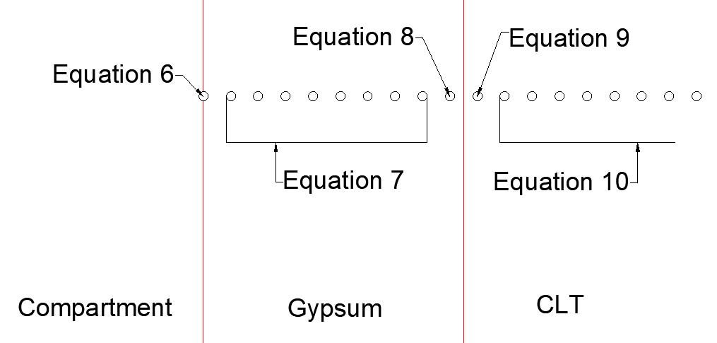
The equations vary at the compartment-gypsum boundary and the gypsum-structural timber boundary as to preserve the homogeneity of the energy transfer. The total energy being inputted into a single node must equal that of the energy out of that node, plus the thermal energy absorbed by that node. The complexities arise due to the combination of both materials at a singular node, requiring more detailed formulae to account for the properties of both materials.
Variables of particular note are those of ∆� and ∆�. These values refer to the incremental distance and time at which each nodal temperature is determined throughout the entire model. These values are crucial to the functionality of the model, as discussed later, and were determined prior to running any computations. ∆� was set at a value of 3mm (0.003m) as this value is neatly divisible across all materials within the cross-section, as well as being sufficiently small enough to smoothly view the propagation of heat flux across the section. ∆� is a value that depends on that of ∆� and was selected as 10 seconds through gypsum mediums, and 20 seconds through the structural timber medium.
The model was run for a total elapsed time of 2400s. This is the longest time to burnout determined in the growth stage analysis of the different fire scenarios. �Y refers to the maximum temperature the fire reaches during the growth stage, before this modelling approach begins, taking a value of 840°C. The Heat Transfer Coefficient, h, is a variable which refers to how well heat is conducted through each medium and combines both values of convective (10 W/m2K) and radiative (35 W/m2K) transfer coefficient to produce a constant total value of 45 W/m2K. The Fourier Number is a value which can be determined using the equation (Eq. 11) listed below and is a dimensionless parameter that characterises transient heat conduction.
�� = sC tu v(∆E )D (Eq. 11)
3.1.3 Material Properties
The equations used for this modelling approach contain variables that relate to the properties of the materials in question. Depending on which node is being determined, these variables are different for each equation. As completed previously for evacuation times, data collection from a variety of industry
15
Figure 26 - Diagrammatic Representation of Applied Equations for Each Node through Cross-Section
suppliers and literature has been conducted to obtain values of the material properties to be applied respectively within each equation. A range of sources have been drawn upon such to account for slight variations in materials and testing methods used to obtain such results, to derive a representative average value. The three variables for which data has been obtained are density, thermal conductivity and specific heat capacity for both gypsum insulation boards and CLT. The average values are displayed in Table 4.
The properties of the gypsum plasterboard cited here are based on K2. Given the importance of the encapsulation, lowering the quality of the gypsum board would not be recommended.
Applying Equation 11 using the average material properties values sourced from literature, alongside the values of ∆� and ∆� aforementioned, the Fourier numbers are determined for both gypsum and CLT below. It can be seen that both the values are within the allowable stability criteria, and therefore the modelling does not oscillate and produce any erroneous results.
3.1.5 Modelling Results
Figures 25 and 26 show the results of the modelling process. The graphs display the temperatures throughout the entire cross-section, with the critical temperatures at the gypsum-CLT boundary, as well as the first CLT lamella boundary highlighted.
3.1.4 Modelling Accuracy and Instability
The accuracy of the model may well be increased through decreasing the values of ∆� or ∆� , however, this would increase the number of nodal points and therefore increase the computation time to unreasonable values. However, the value of ∆� cannot be chosen independently and is determined by stability requirements that are inherent within this modelling approach.
The explicit, discretised approach to one-dimensional heat transfer applied here is not unconditionally stable. This means that although the steady-state values will approach a final residual temperature, the solution may be infringed by numerical oscillations which are physically impossible. To prevent such unstable oscillations, the value of ∆� must be below a certain limit, depending also on ∆� and other variables. This criterion is determined by the coefficient associated with each node at t(p), is greater than or equal to zero. For a one-dimensional interior node, this criterion is such that �� is less than or equal to 0.5.
16
Density, � (kg/m3) CLT Gypsum Average 497 Average 923.4 Thermal Conductivity, K (W/mK) CLT Gypsum Average 0.122 Average 0.266 Specific Heat Capacity, Cp (J/kgK) CLT Gypsum Average 1700 Average 1028.2
Table 4 - Material Thermal Properties
��yF,z{|
��tÖB
= 0.266 ∗ 10 1028.2 ∗ 923.4 ∗ (0.003)K = � ���
= 0 122 ∗ 20 1700 ∗ 497 ∗ (0 003)K = �. ���
4. External Fire Spread
4 . 0 External fire spread
4.0.1 Overview
Requirement B4 of the Building Regulations describes the performance requirements for external flame spread. Protection of the external wall system from an interior fire is provided by the layers of plasterboard. As per figure 26, the numerical model shows that temperatures will not exceed 219o C at the interface. These temperatures are too low to allow ignition of the timber but also are too low to result in any deterioration of any of the non -combustible components.
To guarantee that an external wall system can adequately resist the spread of a fire, it is necessary to demonstrate that the system can withstand an interior fire (i.e. equal fire resistance for the slab and the gap between the slab and the external wall system) and the heat delivered by the external flame projection (i.e. non-combustible materials and cavity barriers). Thermo-mechanical deformations can result in failure of cladding systems, but these will not be analysed here because the temperatures expected will be too low for such deformations to occur.
4.0.2 Façade Detailing
The façade is designed to contain cavity barriers and fire-stopping products to prevent fire from spreading vertically via the exterior cladding. Furthermore, the façade is to contain non-combustible products and gaps around the windows are to be sealed with non-combustible fire-stopping products. The arrangements depicted in the figure below will provide additional insulation and a linear fire stop to protect the interface between the timber and external wall system. Given that the temperatures at the interface between the gypsum encapsulation and the mineral wool insulation are below 219o C at the time for burn-out, mineral wool will not deteriorate at all and therefore it is clear that this arrangement will provide greater fire resistance than the timber slab, thus making sure that an internal fire will not penetrate through the interface between the external wall system and the timber slab.
The combination of non-combustible elements and cavity barriers of the cladding system provides a standard approach to protecting the building from external flame projections. Given that the structural timber does not participate in a fire, the external flame projections will be identical to those of a building with a non -combustible structure. Thus, a standard approach has been deemed to be sufficient.
17
Figure 28 – 3D image of slab edge detail
Figure 27 – Slab edge detail
5
5. 0 Fire fighting
5.0.1 Overview
The building has been designed such that fire service intervention is not necessary in the event of a fire Should the fire strategy be effective, any fire should be able to continue until burnout without endangering the occupants of the building.
Regardless of the above, the building has been designed to facilitate the activities of the fire service and, as much as possible, to create safe conditions for them to operate. The building is to contain a protected core, dry risers and other recommended features defined within Approved Document B.
18
Access and Facilities for the Fire Service
