
100 PROJECTS UK CLT
2
3 Published in 2018 Produced by Waugh Thistleton Architects on behalf of the Softwood Lumber Board & Forestry Innovation Investment Printed in Canada Text © Waugh Thistleton Architects Photographs © as stated Drawings © architects of each project or Waugh Thistleton Architects unless otherwise stated Cover designed by Damon Murray, FUEL All rights reserved No part of this publication may be reproduced without the written permission of the publisher or the copyright owner Special thanks to the CLT providers, engineers, consultants, contractors and developers for their assistance and expertise, without whom this publication would not have been possible: Arup Atelier Ten B & K Structures Binderholz Change Building Egoin Eurban Gardiner & Theobald Hastings Pier Charity Hackney Council Jerram Falkus Kier Eastern KLH UK Lendlease Mace Ramboll School of Engineering, University of Edinburgh Stora Enso Zublin Timber
FOREWORD
While cross-laminated timber (CLT) appears to be finally entering the mainstream, there is considerable inertia in the construction industry that impedes the greater adoption of this truly innovative material. The benefits are clear - building in timber is quick, clean, and easy. It can be achieved with a measured accuracy and lack of noise, waste, or need for material storage space. It has notable benefits in terms of warmth, acoustics, and structural efficiency. In a world ever more concentrated in urban areas, timber is the basis for safe and healthy cities composed of exceptionally designed and responsibly constructed buildings.
The only surprise to us is that the uptake in mass timber has not been faster. Historically there has been a lack of interest in developing construction technology - a serious problem for our field, and for the world at large. If one reflects on the massive demand for housing, the fact that our industry is responsible for such huge energy use and consequent carbon emissions worldwide, and the tremendous influence our industry has over the overall GDP of the United States and all nations, the question is obvious: Why are we not encouraging governments and the building industry world wide to invest in solutions that will solve the problems that affect our society as a whole? And beyond that, can we afford not to?
If we’re going to solve big problems within the architectural realm, our society needs to invest in finding solutions. There is no singular voice or all-powerful entity that defines our profession’s response to the greatest challenges of our time. As a result, we need to amass our voices and generate a change of attitude towards research and innovation into construction.
The work illustrated in this book is the product of a few committed professionals who have labored to prove to clients, contractors, and authorities that any code requirements that are met by concrete and steel can be met and exceeded by timber. These projects start to demonstrate a timber architecture with its own form of expression, perhaps one that will inspire more of our contemporaries to take a step towards solid timber.
5
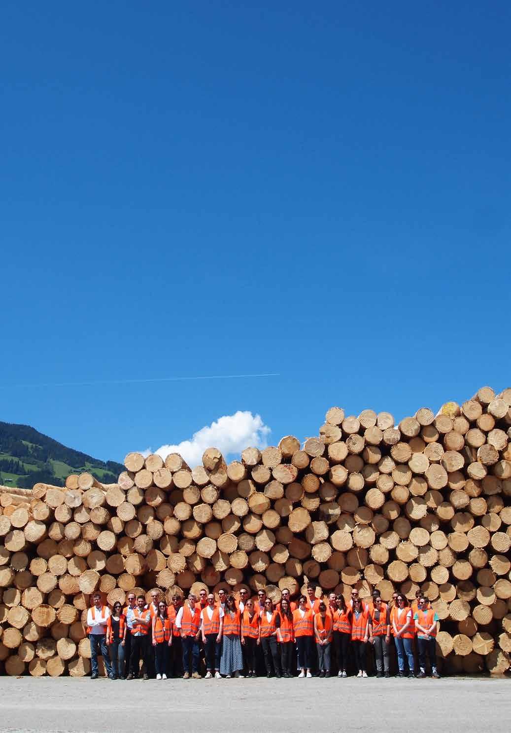
Image: Binderholz sawmill, Austria © Waugh Thistleton Architects

7 ACKNOWLEDGEMENTS 11 INTRODUCTION 13 CLT 14 History 15 Manufacture 16 The Timber 17 Forestry 18 CLT BUILDINGS IN THE UK 20 BENEFITS 27 LIFE-CYCLE ANALYSIS 28 Circularity – End of Life Scenarios 30 REDUCING CARBON INTENSIVE MATERIALS 32 Frame Substitution 32 Reduced Foundations 33 Reduced Secondary Structure and Finishes 33 STRENGTH AND RESILIENCE 34 Fire 35 Seismic Activity and Explosions 35 BENEFITS IN CONSTRUCTION 36 Speed 36 Waste and Logistics 38 Health and Safety on Site 39 HEALTH AND WELLBEING 40 DESIGN FLEXIBILITY AND AESTHETICS 41 CONTENTS
Architects
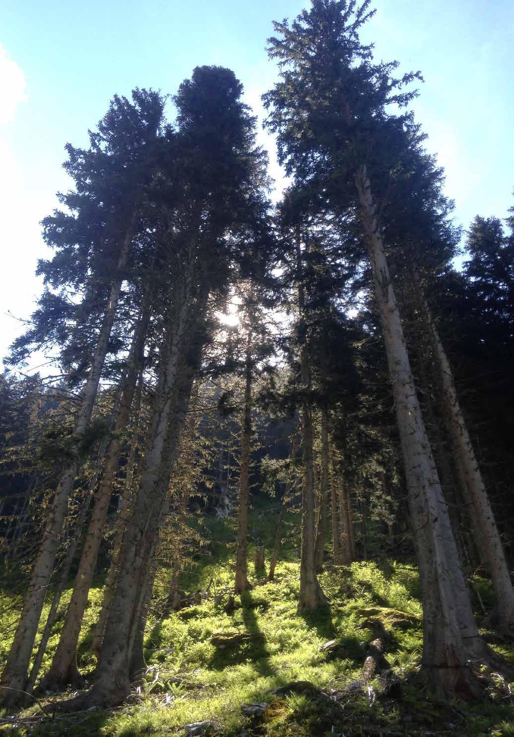
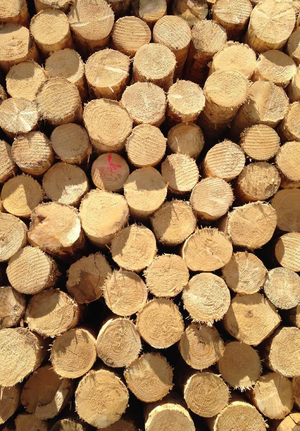
Image: Spruce logs, Austria © Waugh Thistleton
8 DESIGN FACTORS 45 OPTIMIZING 46 Structural Principles 46 Material Efficiency 47 Cutting and Routing 47 Transportation Considerations 48 Hybrid Solutions 50 MATERIALITY 52 Exposed Timber 52 Cladding 52 Water 54 Ventilating the Timber 55 PROCESS 56 Finalizing the Design 56 Building Information Modelling 57 Competitive Tendering 58 MATERIAL PERFORMANCE 61 FIRE 62 Legislation 63 Dealing with Fire Authorities 63 Flammability / Pyrolysis 64 Fire Performance 65 Spread of Flame 65 Connections 66 Sprinklers and Other Suppressive Systems 66 Conductivity 68 Mass 68 THERMAL PERFORMANCE 68 Dynamic Response 69 Air Tightness and Accuracy 70 ACOUSTICS 71 Vibration 73
9 SITE FACTORS 77 OPTIMIZATION 78 Sequencing 78 Ground Works 78 Installation 78 Program Overlap 79 Back-to-Back Processes 79 Lightweight 80 MATERIAL SAVINGS 80 Primary Structure 81 Exposing CLT 81 Delays 82 Deliveries 82 Weather 82 MITIGATING COMMON ISSUES 82 Water 83 Sunlight 83 FIRE 84 Off-Site 85 INSURANCE 86 POST COMPLETION 91 MORTGAGES & SALEABILITY 92 Building Warranties 93 INSURANCE 93 Fire 95 Water 95 MAINTENANCE AND REPAIRS 95 CASE STUDIES 99 CONCLUSION 313 GLOSSARY 315 METHODOLOGY 319 BIBLIOGRAPHY 321
With thanks to the architects/engineers of the 100 schemes for their generous contributions:
5th Studio
6a Architects
ABIR Architects
Arboreal Architecture
ACME
Adam Knibb Architects
Adam Richards Architects
Adjaye Associates
Allford Hall Monaghan Morris
Archer Architects
Architype
Arup
Aukette Swanke
Avanti Architects
Baynes and Mitchell
BDP
Bennetts Associates
Berman Guedes Stretton
Burrell Foley Fischer
Cullinan Studio
David Grindley Architects
David Miller Architects
Dow Jones Architects
10
ACKNOWLEDGEMENTS
dRMM
DSDHA
Duggan Morris Architects
Erect Architecture
Fairhursts Design Group
Feilden Clegg Bradley Studios
Feilden Fowles Architects
Groupwork + Amin Taha
Hale Brown Architects
Hampson Williams
Hawkins\Brown
Haworth Tompkins
Hayhurst and Co.
Henley Halebrown Architects
Hewitt Studios
Hodder + Partners
Horden Cherry Lee Architects
Hugh Strange Architects
Jeremy Bailey Architects
Jestico + Whiles
John Pardey Architects
Karakusevic Carson Architects
Kay Hartmann Architects
Levitate
LSI Architects
Malcolm Fraser Architects
Matthew Lloyd Architects
Meadowcroft Griffin Architects
Mole Architects
Mosley and Mann
Nicholas Hare Architects
Penoyre & Prasad
Pringle Richards Sharratt
Quay 2 c Architects
Rundell Associates
Sarah Wigglesworth Architects
Saville Jones Architects
Sheppard Robson
Softroom Limited
Spheron Architects
TECTONICS Architects
Theis and Khan Architects
Tonkin Liu
Urban Projects Bureau
Waugh Thistleton Architects
WilkinsonEyre
Wilkinson King
11
INTRODUCTION
The world is in the midst of a housing crisis with a global mass migration to cities. The UN predicts that 66% of the world’s population will be resident in urban areas by 2050.1 In order to deal with this flow of people, the way housing is delivered in our cities needs to be addressed with more high density, mid-to-high rise buildings required.
The implications of this in terms of climate change are considerable while urban structures are predominately built in steel and concrete. The production and use of cement is responsible for approximately 8% of the world’s CO2 emissions, 2 a figure that will increase if urban construction trends continue. At the same time a gradual decline in construction productivity over the past 50 years presents further challenges in meeting the growing demand for homes.3
Timber, nature’s own building material, is both replenishable and sustainable, offering an alternative way of meeting the growing housing demand. If we build in timber, as opposed to traditional materials with high levels of embodied carbon, we can save an average of 45 tons (40 tonnes) of CO2 per dwelling. 4 At a global scale this can make a vital difference.
Traditionally, timber has not been used for high density buildings. However, the recent development of mass timber products has enabled timber to compete structurally at scale. Highly engineered products that overcome many of the issues associated with traditional timber frame have put wood construction back in the running.
This report sets out a study into 100 of the most significant buildings constructed from CLT in the United Kingdom over the past 15 years. We have contacted a wide range of individuals and businesses to interview them about their experiences building in CLT. The opinions have been collated and the findings set out in these chapters. Following these we have appended details of the 100 projects from the study and the names of the consultants, contractors and clients involved.
13
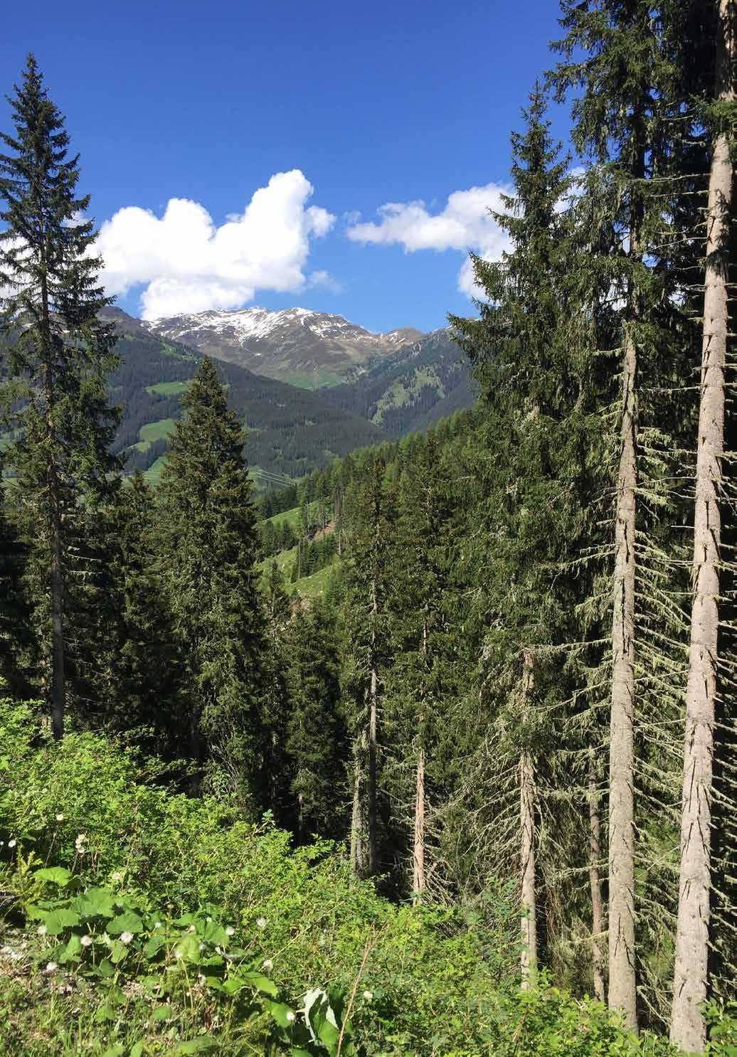
Image: Softwood forest, Austria © Waugh Thistleton Architects
CLT
The emergence of cross-laminated timber (CLT) over the last two decades has provided a viable alternative to concrete and steel construction.
Devised less than twenty five years ago, CLT is a modern timber product, which utilizes a range of species and grades for high performance applications. Cross-laminating is a way of optimizing varying grade softwood to create boards with a high and predictable strength.
CLT panels consist of layers of structural lumber boards stacked in perpendicular layers and glued together under high pressure. A crosssection of a CLT panel is typically fabricated with three to nine layers of boards. By alternating the orientation of the layers of wood, expansion and shrinkage in the plane of the panel is minimized. The result is a considerable increase in stability and structural capacity.
The engineered composite formed through the lamination enables taller, stronger, more stable and safer timber structures that are able to comply with the more onerous demands of high-density building. In this way the multiple issues that have prevented timber frame from entering urban typologies can be overcome.
Broadly speaking, using CLT allows us to construct lighter, better quality buildings, more quickly, with reduced foundations and fewer deliveries to site. This method of construction leads to safer, cleaner, quieter sites, with a reduced number of workers and consequently less nuisance to neighbors in a dense urban site.
The material itself contributes to thermal and acoustic insulation and has verifiable health and well-being benefits. The timber structure locks carbon within its fabric, an intrinsically sustainable and modern approach to construction that produces high quality, high performance buildings.
14
HISTORY
CLT has its origins in the traditional timber technologies of central Europe and Scandinavia. Modern CLT resulted from joint research between industry and academia in Austria in the mid 1990s and its development has been supported by ongoing research.
In the early years, a few small timber manufacturers in the sub-Alpine regions of Germany, Austria and Switzerland experimented with the new composite and it was used in the construction of buildings up to three storeys.
In the early 2000s, manufacturing and construction techniques had matured enough for full-scale production to begin. The use of CLT spread across Europe and developed particularly in the UK.5
As the reputation of the technology has spread, other European countries have begun to set up their own manufacturing facilities.
15 90 o
MANUFACTURE
CLT is made from boards of timber, approximately 1-2 inches (20-40mm) thick, which are sorted, finger jointed together into long strips and arranged side by side to form layers. These are glued and pressed to form panels of multiple layers (minimum of 3). Each layer is at 90 degrees to the one before, forming the cross-lamination.
Lumber boards are kiln dried to a moisture content of 10-14% 6 which assists with adhesion and reduces dimensional variations and surface cracking. Defects that influence the strength of the boards, such as large knots, are removed and the boards are trimmed and finger jointed to obtain the desired lengths and quality of lumber.
The panels are assembled by placing the boards side-by-side to form solid wood layers. Each successive layer is laid perpendicular to the preceding layer with adhesive being applied between layers. Once assembled the board is then pressed, in either a large hydraulic or vacuum press, and finally cut to size and/or milled to specification.
In Europe, two glues are typically used in CLT production: PUR, polyurethane based adhesives, or, less commonly MUF, Melamine-Urea-Formaldehyde based. PURs are preferred as they are solvent and formaldehyde free ensuring low toxicity and aiding future re-use or recycling, however the adhesive selection can be influenced by fire requirements.7
A test of five different CLT panels indicated no impact on internal air quality by the emission of volatile organic compounds (VOCs) from the CLT. 8
16 60% 40%
Biomass power
Biomass fuel + animal bedding
-7% during kiln drying -15% through cutting + planing
Wood chips + sawdust
CLT
panels for distribution
is a closed loop process in which most waste is
The
The production of CLT
reused.
diagram shows the principal activities and efficiency.
CLT is produced at a variety of qualities to meet the requirements of various applications. Generally, this range is non-visible quality (NVQ), industrial visible quality (IVQ), and visible quality (VQ), decreasing in visual imperfections and increasing in appearance quality respectively.
The various manufacturers produce panels of different dimensions, the size of which is impacted by the constraints posed by transportation. While larger panels can be manufactured, their delivery can require special measures such as notification of authorities, road lane closures and police escorts, adding complexity and cost.
THE TIMBER
The timber species that are typically used for CLT are coniferous, evergreen softwoods predominantly Spruce, with varying quantities of Douglas Fir, Western Larch and Pine. 9
A typical tree harvested for CLT will be around 80 years old and 100ft tall.10 Sawmilling has a yield rate of around 60% by volume. The kiln drying, planing and cutting causes a further 25% loss. As a result, from every 100ft 3 of log around 45ft 3 of CLT can be produced (0.43m 3 CLT from 1m 3 log).11
In most CLT plants the lost material is not wasted - all of the offcuts and sawdust are processed into co-product and biomass that is used to run the factory equipment, the kiln and provide fuel for local communities.12 This is an optimized process that allows most production to be self-sufficient in terms of energy use.
Comparing the fast growing softwoods used in CLT manufacture with typical hardwoods.
17 50 m SPRUCE Height: 30-55 m Mature age: 80-120 years Maximum age: 150-250 years C O N IFE R OU S DECIDUOU S FIR Height: 30-40 m
age: 90-130 years Maximum age: 500-800 years BEECH Height: 30-35 m Mature age: 100-140 years Maximum age: 200-300 years OAK Height: 20-30 m Mature age: 120-200 years Maximum age: 500-800 years 40 m 30 m 20 m 10 m
Mature
FORESTRY
The Forest Stewardship Council (FSC) and Program for the Endorsement of Forest Certification (PEFC) are certification bodies for the forestry industry. In addition to country regulations, third-party certification confirms that forests are managed in a responsible and sustainable way ensuring diversity, supply and good conditions for workers. Across the world over 1 billion acres of forest is certified, with 16% of this having both PEFC and FSC certification.13
This certification is only awarded to products when chain of custody certificates demonstrate that all companies that have handled and processed the timber are accredited. In this way a fully sustainable industry is maintained.
Most CLT manufactured in Europe is produced from timber grown and harvested in Austria and Germany. Both are heavily forested at 48% 14 and 32% 15 respectively, with established forestry industries.
Despite felling, forest coverage in Austria and Germany is increasing year on year.16 The managed forests from which the timber for CLT is sourced are contributing to an increase in forest coverage. Controlled harvesting from these forests must be distinguished from global concerns of deforestation.
Timber is the only mainstream construction material that can be considered as truly replenishable due to the speed at which it grows. PEFC and FSC are the most established regulatory and certification bodies for a construction material’s sourcing ensuring the production of timber is fully sustainable.
In Austrian and German forests alone, enough timber is grown within one hour to produce the CLT required for Dalston Works (pg. 228-229), currently the largest timber building in the world. On this measure, an average dwelling of 1,000ft 3 (30m 3) would be grown every 20 seconds with the 2,440,000 ft 3 (70,000m 3) of CLT used for the 100 case studies growing in 14 hours.17
Image:
18
Softwood forest, Austria © Waugh Thistleton Architects
CLT BUILDINGS IN THE UK
The UK has one of the most diverse range of CLT buildings in the world. The reasons behind this are multiple and varied, however one key driver is the nature of the legislative structure that governs construction in the UK.
The construction regulations of most countries define specific parameters to which the design must adhere. These regulations will tend to dictate the maximum height for buildings constructed from a combustible material, such as timber. Typically, a maximum number of storeys is prescribed for a fully exposed, partially exposed and fully encapsulated structure. In such environments, the limits can only be increased by a change in the law.
In contrast, the UK building regulations are descriptive rather than prescriptive. They indicate a series of performance requirements and it is the responsibility of the design team and consultants to demonstrate that the proposed solution meets these criteria.
CLT buildings in the UK have to meet the same performance criteria as other building methods and the uptake has not been a completely smooth and effortless journey. This modern method of construction has been advocated and pioneered by architects and engineers across the UK who have gradually overcome the various barriers that have stood in the way.
The extensive portfolio of CLT buildings in the UK demonstrates how engineered timber has and can be used across a range of sectors. Each of the 100 schemes detailed demonstrates an application of CLT and sets a precedent to further the use of CLT in the UK and the rest of the world. The map of the United Kingdom shows the locations of the 100 case study projects.
20
21 Commercial Educational Public/Civic Residential Key
22 Commercial Educational Public/Civic Residential Key
This enlarged map illustrates the spread of the 48 case studies built within London; which has become a key focal point for the use of this material.
Even within the capital, hot spots of CLT construction can be identified, for example the London Borough of Hackney. This high concentration of engineered timber buildings is a reflection of Hackney Council’s commitment to sustainability. In 2012 the local council came close to implementing a ‘Timber First’ policy,18 whereby planning applications would have to demonstrate that a timber solution had been investigated as an option for each scheme proposed within the Borough.
While policy was not implemented it is evident that to a preference for and knowledge of timber within the local government has had an impact on construction within the Borough.
“When I saw Murray Grove, the world’s first 9 storey residential timber building in Hackney, it was clear that there was real potential for a step-change in sustainable construction. I am delighted and proud that Hackney has played a part in the story of tall timber buildings. I hope this will encourage others to embrace engineered timber in construction.” Councillor Vincent Stops, Hackney Council.
23
1 United Nations, World Urbanization Prospects, The 2014 Revision, Highlights (New York, United Nations, 2014).
2 PBL Netherlands Environmental Assessment Agency and European Commission Joint Research Centre, Trends in Global CO 2 Emissions, 2016 Report (The Hague, PBL Publishers, 2016), p.64.
3 National Society of Professional Engineers, ConstructionProductivity in Decline, 2014. <http://www.leanconstruction.org/media/docs/PEJune14_ Construction.pdf> [accessed 20 September 2017].
Cardiff Garcia, ‘The remarkable productivity stagnation of the US construction sector’, Financial Times, 2014 <https://ftalphaville. ft.com/2014/04/15/1821522/the-remarkable-productivity-stagnation-of-theus-construction-sector/> [accessed 20 September 2017].
4 Mike Berners-Lee, ‘What’s the carbon footprint of... building a house’, The Guardian, 2010 <https://www.theguardian.com/environment/greenliving-blog/2010/oct/14/carbon-footprint-house> [accessed 8 September 2017]. Embodied carbon figures from a cross section of CLT case study projects.
5 FP Innovations and Binational Softwood Lumber Council, CLT handbook:cross-laminatedtimber/editedbyErolKaracabeyli,BradDouglas, U.S. ed. (U.S. Department of Agriculture, Forest Service, Forest Products Laboratory, Binational Softwood Lumber Council, 2013).
6 Questionnaire from Kay Hartmann, KLH UK, 11 September 2017.
7 Questionnaire from Daniel Kreissig, Zublin Timber, 22 September 2017.
8 FP Innovations and Binational Softwood Lumber Council, CLT handbook:cross-laminatedtimber/editedbyErolKaracabeyli,BradDouglas, U.S. ed. (U.S. Department of Agriculture, Forest Service, Forest Products Laboratory, Binational Softwood Lumber Council, 2013).
9 Questionnaire from Kay Hartmann, KLH UK, 11 September 2017.
10 proHolz Austria, Wald in der EU, Zuschnitt, No. 51 (2013), pp.15-16.
11 Email from Christof Richter, Research and Design at Binderholz, 05 April 2017.
12 KLH UK, FrequentlyAskedQuestions, 2017 <http://www.klhuk.com/ media/11553/frequently%20asked%20questions_05042011_1.pdf> [accessed 10 July 2017].
13 PEFC, Facts & Figures, 2017 <https://www.pefc.org/about-pefc/ who-we-are/facts-a-figures> [accessed 20 September 2017].
24
Endnotes
14 Republic of Austria, Federal Ministry of Agriculture, Forestry, Environment and Water Management (BMLFUW), Sustainable forest management in Austria, Austrian Forest Report, 2015 <https://www.bmlfuw. gv.at/english/forestry/The-Austrian-Forest-Report-2015--Austria-s-forestsreceive-top-grades.html> [accessed 19 September 2017].
15 Federal Ministry of Food and Agriculture (BMEL), The Forests in Germany, Selected results of the Third National Forest Inventory, 2014 (Translation 2015) <https://www.bmel.de/SharedDocs/Downloads/EN/ Publications/ForestsInGermany-BWI.html> [accessed 19 September 2017].
16 BMLFUW, Austrian Forest Report, 2015. BMEL, The Forests in Germany, 2014.
17 BMLFUW, Austrian Forest Report, 2015. BMEL, The Forests in Germany, 2014.
18 Will Hurst, Hackney moots ‘timber-first’ planning policy, Building online, 17 May 2012 <http://www.building.co.uk/hackney-moots-‘timberfirst’- planning-policy/5036737.article> [accessed 20 August 2017].
25
As humanity reassesses its relationship with the planet from one of exploitation to one of investing and protecting our natural assets, so we transition from using materials that are extracted from the ground and pollute the atmosphere, to prioritizing the use of that which is naturally grown. This process will start to reverse the damage to the environment caused by mass global industrialization over the last two centuries.
Trees provide us with an abundant, replenishable source of material. When used in buildings, timber offers unsurpassed benefits to the health and wellbeing of those involved in the construction, those living nearby and those that live or work inside the completed building.
In terms of the planet, one of the greatest attributes of timber is that it absorbs carbon during growth. By using more timber in the construction of our buildings we can remove increased amounts of carbon from the atmosphere. By producing buildings that act as carbon stores, we can make a significant contribution to carbon reduction and help to mitigate the impact of climate change.
27
BENEFITS Image: Roundwood, Austria © Waugh Thistleton Architects
LIFE-CYCLE ANALYSIS
Carbon exists throughout the planet as reservoirs - forests, oceans and open land have significant potential for both storing and emitting carbon. The constant movement of carbon between these various states is known as the carbon cycle. Balanced levels of carbon in the atmosphere are maintained through absorption and emission on the surface of the planet.
The recent increased combustion of fossil fuels that had stored carbon for millennia has disrupted the carbon cycle, increasing the concentration of carbon in the atmosphere and creating change in our climate. Given the time scale over which these stores were created, the released carbon will not be re-absorbed at a fast enough pace to reverse the damage already caused and to stop severe climate change.
Comparatively the carbon cycle within a forest is dramatically shorter with carbon storage within trees taking decades as opposed to millennia. As trees grow they absorb carbon dioxide from the atmosphere for photosynthesis, they then release the oxygen and store the carbon within the wood. As a tree approaches full size the rate of this carbon sequestration plateaus. Eventually the tree will die and decay slowly releasing the carbon back into the atmosphere, a natural part of the lifecycle of a forest.
In managed forests the trees are felled before the end of this lifecycle. The carbon remains within the harvested timber. For each tree that is felled others are planted in its place. Additional planting year on year ensures a net increase in the carbon stored within managed forests despite harvesting.
All timber products, including CLT buildings, act as carbon stores. Effectively, when we build in timber from sustainably managed forests we are increasing the capacity of the world’s carbon sink. The scale of today’s construction industry offers the opportunity to create a new carbon reservoir within the fabric of timber buildings.
28
The Carbon Cycle - it is estimated that there is about 30% more carbon dioxide in the atmosphere today than there was 150 years ago. Ice cores show that there is now more carbon dioxide in the atmosphere than there has been in the last 420,000 years.
29
CARBON
STORED
ATMOSPHERIC
FOSSIL FUELS CARBON
DIFFUSION PHOTOSYNTHESIS FOSSILFUELSFOR ENERGY DECOMPOSITION COMBUSTION RESPIRATION
CIRCULARITY – END OF LIFE SCENARIOS
As part of the overall impact of a building, the whole life carbon cost should be considered, especially where the stored carbon is a factor. We must consider that in the next 50 years some of the early CLT buildings will be decommissioned and, while the timber can be used for fuel, it would be preferable for the carbon storage to be extended through reuse or recycling.
As a new technology there are few precedents set for end of life recycling or reuse. However, at this early stage in CLT’s development we have the opportunity to plan for this now. We can design with the objective of maintaining the CLT as a carbon sink when a building is decommissioned; designing for reuse and recycling, rather than energy production.
Forests
Wood can be burned for clean energy
Trees are a renewable resource and store carbon.
Wood products can be reused or recycled to create new products.
Timber buildings store carbon in their structures for the period of their maintained life.
Manufacturing processes typically use all parts of the log, producing no waste and little pollution
30
absorb CO2 from the atmosphere through photosynthesis.
© Yugon Kim
Contaminants are the most significant obstacle to wood recycling. Research by The Waste and Resources Action Program (WRAP) outlines the cost and time implications of removing contaminants, and highlights that preventing contamination in the first place is the best and easiest method to ensure that wood can be recycled and reused.1
The glues typically selected for CLT manufacture are low hazard, meaning that the panels that leave the factory can be recycled or reused. By keeping re-use in mind during the design stage, designers can ensure that the CLT is not treated with toxic products, which would inhibit recycling.
An example of how this is achieved is the Sky Health and Fitness Centre (pg.250-251). Structural and fire engineering design allowed the CLT to be exposed whilst avoiding the need for almost all applied spread of flame treatment. Considering the reuse at the early stage of design has ensured that the panels used within this scheme have a greater potential for recycling at the end of the building’s life. 2
The cascade principle is based on the idea that the value of a product, both in terms of its material and capital should be maintained for as long as possible to maximize a material's useful life. In essence a CLT panel is a high quality and valuable product that can be repeatedly processed into lower quality products with use as biofuel being the last and final option. The benefit here is that each new life the material is given extends the period for which it remains a carbon store.

31
Sky Health and Fitness Centre, dRMM © Paul Carstairs/ARUP
REDUCING CARBON INTENSIVE MATERIALS
FRAME SUBSTITUTION
The processing, manufacture and transportation of modern timber products result in a significantly lower embodied carbon figure than other, traditional construction materials.
It is not straightforward to directly compare the embodied carbon of one ft 3 or a pound of a specific material as the volume or weight of material used for the same building will vary depending on the structural system and performance. Research studies have compared the embodied carbon of concrete, steel and hybrid structural frames, all generally illustrating a similar level of embodied carbon, at around 55lbs.CO2/ft 2 (225kgCO2/m 2) for the superstructure of an open plan commercial type building.3 This embodied carbon figure is for ‘cradle to site’ incorporating extraction, processing and delivery.
Comparatively based on the open plan pure timber commercial buildings in our study, the equivalent embodied carbon of the timber structure, not including the sequestered carbon, is 12lbs.CO2/ft 2 (63kgCO2/m 2). By substituting a CLT frame for a concrete or steel structure the embodied carbon of the building can be vastly reduced.
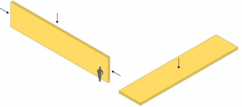
The diagrams illustrate that a CLT frame includes internal walls, as well as structure, compared to a reinforced concrete frame, which requires infill.
32
REDUCED FOUNDATIONS
The design of any engineered timber building must ensure that the timber is protected to avoid contact with moisture that could cause mold growth or decay. In most instances, concrete or other masonry materials are used for the foundations of timber buildings.
While timber should rarely be used for below ground works, the weight of a CLT structure can significantly reduce the requirement for foundations, resulting in an overall reduction in the volume of concrete used for the ground works as compared to a traditional build. 4
REDUCED SECONDARY STRUCTURE AND FINISHES
In contrast to most frame technologies, CLT panels can be utilized to form entire walls, floors and roofs which reduces, and in some cases removes, the need for any secondary structure. In addition, when exposed as an internal finish, the use of CLT reduces the volume of finishing materials required to line walls and form suspended ceilings.
Reducing the volume of high-embodied carbon secondary materials, such as dry wall or aluminium cladding, can significantly further reduce the carbon footprint of the building.
33
The diagram indicates an approximate reduction in the raft foundations required for a CLT version of the Dalston Works scheme.
STRENGTH AND RESILIENCE
Cross-laminated timber and glulam offer high strength to weight ratios that in many cases equal those of steel and reinforced concrete.5
CLT panels provide high levels of strength throughout the structure. This strength is demonstrated both in-plane, resisting shear forces and carrying load and out-of plane, where a panel acts as a bending slab. This two-way load resistance is similar to the behavior of reinforced concrete. 6
Additionally, the cross lamination ensures high levels of dimensional stability with little deformation of the panels to in-plane load. Out-of-plane load, and in particular localized compressive load, for example in a floor slab at the base of a wall panel, is more likely to result in deformation, however this is able to be calculated precisely and accounted for within the dimensioning of an overall structural frame.
CLT can resist load both as a beam (ie. in-plane), or a slab (out-of-plane)
Where the compressive load is likely to be high, for example at the lower levels of a multi storey building, slab panels can be reinforced by using localized grout pockets or by driving screws or hardwood dowel into the timber as reinforcement.
34
Innovative engineered timber panels are currently under development which include hardwood and carbon fiber layers within the panel leading to substantial increases in strength.
FIRE
A key advantage of CLT is its inherent fire resistance. In most cases, the charring of the timber surface during a fire protects the material beneath which maintains its structural integrity. In this way, significant structural fire protection can be achieved within the material items and CLT panels can be produced with fire resistances of up to 60 minutes.
In practice, a combination of the timber charring and fire resistant boards are commonly used to achieve the necessary fire rating.
Great care should be taken with regard to the resistance to fire and the potential for escape from all buildings, whatever their construction material. The fact that timber is a combustible material encourages the designer of timber buildings to pay particular attention to these issues, although this should be the case for all buildings.
SEISMIC ACTIVITY AND EXPLOSIONS
Under exceptional loads, such as from earthquakes, CLT and its connections flex and absorb energy from the vibrations, acting as a damper. This is in contrast to concrete and steel, which are more likely to fracture or disintegrate under these forces.7
The most robust study to date to quantify the seismic behavior of CLT construction is the SOFIE project undertaken by the Trees and Timber Institute of Italy. A seven storey structure was shown to be able to withstand significant sustained vibration, up to the strength of the Kobe earthquake of 1995 without any significant damage. 8
Last year the U.S. Department of Defense subjected CLT and other materials to a series of live blast tests which showed in slow motion the way in which the timber bows and absorbs much of the energy of the blast, resulting in little permanent damage. 9
35
BENEFITS IN CONSTRUCTION
SPEED
The program savings that can be achieved using CLT are generally considered the most significant benefit and biggest cost saving associated with this system of construction. Typically, the overall construction of a CLT scheme will be 20% faster than an equivalent scheme in reinforced concrete. This time saving is not only the result of the speed at which the pre-fabricated elements of CLT are erected, but of the significant time savings in the later stages of construction. These gains are principally acheived through the accuracy of the finished structure, the structural stability, concurrent working and the ease of fastening into timber.
Both installation of the prefabricated CLT panels and subsequent works are easier, quieter and safer, reducing or completely avoiding wet trades and reducing the number of personnel required to erect the superstructure by around 50-70%.10
The Gantt chart indicates the approximate program adjustments that would be expected for a CLT scheme compared with a traditional reinforced concrete build.
36
0 20 40 60 80 100 120 CLT Completion Works Concrete Completion Works CLT Fit Out Concrete Fit Out CLT External Envelope Concrete External Envelope CLT Superstructure Concrete Superstructure CLT Substructure Concrete Substructure 2 0 W E E K S 4 0 W E E K S 6 0 W E E K S 8 0 W E E K S 1 0 0 W E E K S
KLH UK lists the following approximate time savings for various aspects of the build: 11
- Services (MEP) – approx. 30-50% faster
- Dry liners – approx. 20-30% faster
- Window & door installers – approx. 20-30% faster
- Insulation installers – approx. 20-30% faster
- Cladding installers – approx. 20-30% faster
Reduction in program time has financial benefits in reducing on-site overheads, shortening loan terms, personnel costs and allowing for the earlier occupation of buildings.
The reduced program offered by CLT can also enable time critical projects to be realized. This can be a crucial consideration for many projects, including schools, for which funding periods can be set and term time dates and new intake levels fixed.
81% of the education case studies stated that time savings were one of the primary factors in the choice of CLT for their project.
37
Education projects that highlighted speed as a primary benefit
Projects accross all the sectors that highlighted speed as a primary benefit
81% 58%
WASTE AND LOGISTICS
A typical CLT structural frame is prefabricated off-site and includes openings and service voids. As a result of this there is almost no waste from the erection process of the structure. This can have benefits in terms of the site operations in that there is no need to take up large areas for site waste storage prior to disposal.
Savings in site logistics are also achieved from the ability to crane panels directly and quickly into place from a delivery vehicle. Frequently the erection of the frame can be undertaken using a mobile crane eliminating the requirement for a tower crane, with the expense and additional structure they require.
38
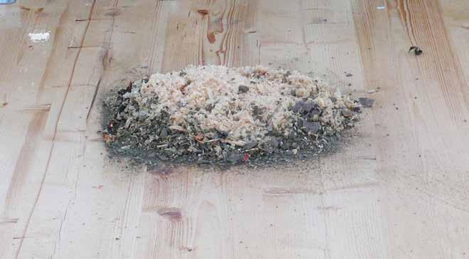
Waste from one week during the erection of the CLT frame at Stadhaus/Murray Grove
HEALTH AND SAFETY ON SITE
With the reduction in material and weight, there is a reduction in the labor required to construct a pre-fabricated CLT frame, and the health and safety considerations on site can therefore be commensurately reduced. Furthermore, the completion of entire solid walls concurrently with floors reduces the risk of falls from height and gives a dry and warmer working environment. Where stairs are also included in the frame, each completed level offers a safely accessible workspace with limited need for additional protection.
The construction of CLT buildings is quieter and creates less dust and waste than traditional construction sites. This makes for better working conditions for construction workers and a cleaner local environment, an important issue particularly in urban locations.
In comparison to a concrete or steel construction site, the noise levels from CLT construction are dramatically lower. Because the panels are prefabricated to minute tolerances there is no heavy machinery required on site. The majority of work involved in fixing into the timber is achieved with cordless power tools. This makes for both a significantly quieter and less toxic working environment.
Furthermore, the timber itself absorbs airborne vibrations significantly reducing reverberant noise levels both on and off site. The inclusion of external walls within the superstructure means that the majority of the working space is partially enclosed which further limits sound nuisance to neighboring properties.
Deliveries of the structure are also greatly reduced, often by as much as 80%.12 The effect of construction site deliveries on the urban environment in the UK is becoming an increasingly widely discussed issue. Pollution from engine fumes and tires has been demonstrated to have a major impact on air quality in the urban areas of the UK.13
39
HEALTH AND WELLBEING
In 2015, Planet Ark, an Australian not-for-profit, environmental organisation. published a review of studies analysing the health and wellbeing benefits of wooden interiors in homes, businesses, schools and hospitals.
“We know that workers are less stressed and more productive, students learn better, patients heal faster, and people are generally happier and calmer in indoor areas which contain wooden elements,” says David Rowlinson.14
The review identified that the increased use of wood has measurable physiological and psychological health benefits. Exposing timber in interiors has a number of measurable health benefits for inhabitants including reduced blood pressure, heart rate and stress levels. Studies also show that living or working in a wooden interior can improve a person’s emotional state and their level of self-expression.15
In schools, this can include greater levels of attention and receptiveness to learning. At the Ickburgh School (p.136-137), the head noted that the wood had a beneficial impact on the stress levels and behavior of the children.
The review identifed studies that show that the presence of wood in offices can dramatically improve visitor’s impression of the company, conveying feelings of innovation, energy and comfort. Companies with timber interiors report higher levels of staff retention, greater levels of productivity and lower levels of sickness.
In addition to the psychological and physiological effects of timber, the use of wood has a beneficial effect on air quality through moderating levels of humidity, absorbing moisture in humid conditions and releasing moisture in dry conditions. This also reduces discomfort from high humidity that often accompanies high temperatures.
Another feature of wood is that it does not become electrically charged, which inhibits the raising of dust, reducing allergens and increasing the quality of life for those suffering with respiratory problems.16
Timber surfaces and massive timber panels have an acoustic benefit, absorbing sound and so improving comfort, particularly in more public environments.
40
DESIGN FLEXIBILITY AND AESTHETICS
A structural system that is entirely timber offers opportunity for new forms of architectural expression. This provides us with an extensive range of innovative and distinctive buildings, many examples of which are included in the case studies in this book.
These illustrate the simple composite action that CLT construction enables, where walls and balustrades can act as beams above slabs and cantilevers can be achieved with the straightforward extension of a slab. Multiple load paths allow engineers to create efficient, well-honed structures, leading to a range of structural possibilities.
At the mixed-use building on Whitmore Road (pg.192-193) the party walls between the apartments at the top of the building act as deep beams holding the roof of the open plan photographic studio beneath. Similarly, the complex folded roof of the house extension at Hunsett Mill (pg.180181) is designed to be stiff enough to support the first floor which is hung beneath.
The high strength to weight ratio and the low thermal conductivity make cantilevers straightforward to form. Examples within the case studies include the roof of the Queen Elizabeth Olympic Park Timber Lodge (pg.294-295) and the Wedding Chapel in the Tower of Love pavilion (pg.282-283).
The natural beauty of the raw material provides an attractive internal finish with the added expedient of not having to line out the structure. Many of the case studies demonstrate how this advantage has been exploited.
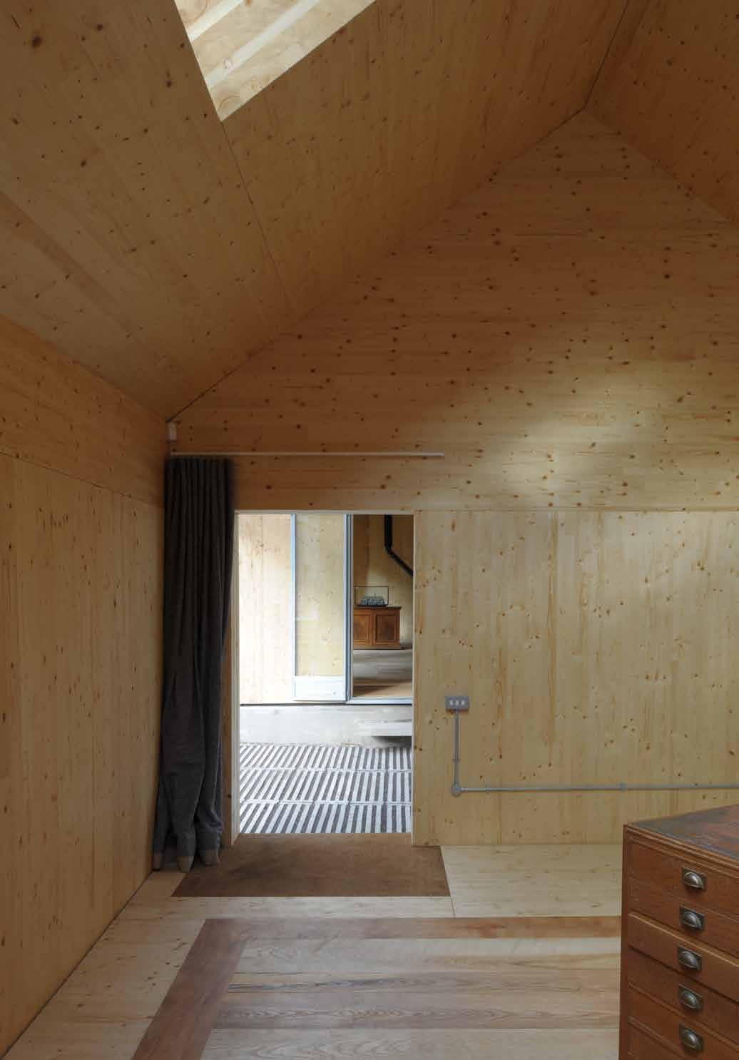
The monolithic Architecture Archive (pg.244-245) exposes almost the entire structure both internally and externally. Similarly, Barrett’s Grove (pg. 206207), a development of six homes, exposes all internal walls and ceilings.
41
1 Ijeh, I., Recycling Timber: Wasting away, Building online, 28 October 2015 <http://www.building.co.uk/recycling-timber-wasting-away/5078393. article> [accessed 20 August 2017].
2 Adrian Campbell, Change Building, interview by R.Sawcer & K.Walker, London, 14 August 2017, Waugh Thistleton Offices.
3 Cundall Johnston & Partners LLP, Embodied carbon of steel vs concrete buildings, Information paper – 31, 2013 <http://www.cundall.com/ Cundall/fckeditor/editor/images/UserFilesUpload/file/WCIYB/IP-31%20 -%20Embodied%20carbon%20versus%20steel%20v%20concrete%20 buildings.pdf> [accessed 15 June 2017].
4 Gavin White, Ramboll, Interview by A.Thistleton & R.Sawcer, London, 8 September 2017, Waugh Thistleton Offices.
5 Structural Timber Association, Timber as a structural material - an introduction, Structural Timber Engineering Bulletin 1, 2014 <http://www. cti-timber.org/sites/default/files/STA_Timber_as_structural_material.pdf> [accessed 10 July 2017].
6 Gavin White, Ramboll, Interview by A.Thistleton & R.Sawcer, London, 8 September 2017, Waugh Thistleton Offices.
7 Gavin White, Ramboll, Interview by A.Thistleton & R.Sawcer, London, 8 September 2017, Waugh Thistleton Offices.
8 National Research Council of Italy, Trees and Timber Institute, The SOFIE project, 2007 <http://www.ivalsa.cnr.it/en/current-projects/ediliziae-architettura/progetto-sofie.html> [accessed 10 August 2017].
9 Joyce El Kouarti, U.S. Forest Service Office of Communication in Forestry, Build Better, Stronger, Faster with CLT, 2017 < https://www.usda. gov/media/blog/2017/04/04/build-better-stronger-faster-clt> [accessed 10 September 2017].
WoodWorks, Wood Products Council, Woodworks Leads Blast Testing Project for Cross-Laminated Timber, 2016 <http://www.woodworks.org/wpcontent/uploads/Blast-Testing-News-Update-Dec-12-2016.pdf> [accessed 10 September 2017].
WoodWorks, Video recordings, 2016 <https://www.youtube.com/ channel/UCsy22KwkQ-1xUtlfUU2u3fg/playlists?view=1&flow=grid&sort= da> [accessed 10 September 2017].
10 Questionnaire from Liam Dewar, Eurban, 15 September 2017.
11 KLH UK, Frequently Asked Questions, 2017 <http://www.klhuk.com/ media/11553/frequently%20asked%20questions_05042011_1.pdf> [accessed 10 July 2017].
12 Questionnaire from Liam Dewar, Eurban, 15 September 2017.
42
Endnotes
13 Robin McKie, Smog in the cities: the truth about Britain’s dirty air, The Guardian, 2017 <https://www.theguardian.com/environment/2017/ jan/29/pollution-air-quality-london-environment> [accessed 8 September 2017].
14 Damian Carrington, Electric cars are not the answer to air pollution, says top UK adviser, The Guardian, 4 August 2017 <https:// www.theguardian.com/environment/2017/aug/04/fewer-cars-not-electriccars-beat-air-pollution-says-top-uk-adviser-prof-frank-kelly> [accessed 10 September 2017].
15 Planet Ark, Make it Wood, Housing, Health, Humanity, 2015 <http:// makeitwood.org/documents/doc-1253-wood--housing--health--humanityreport-2015-03-00-final.pdf> [accessed 20 November 2017].
16 Planet Ark, Make it Wood, Housing, Health, Humanity, 2015 <http:// makeitwood.org/documents/doc-1253-wood--housing--health--humanityreport-2015-03-00-final.pdf> [accessed 20 November 2017].
Sandra van Dijk, Wood improves are quality, moderates humidity, Climate Control News, 27 March 2017 <http://www.climatecontrolnews.com. au/ventilation/wood-improves-air-quality-moderates-humidity> [accessed 20 November 2017].
43
DESIGN FACTORS
As a high quality engineered product, the material cost of CLT is typically around 30-40% higher by building volume than traditional structural materials. The cost is determined by a range of factors including the dimensions, quantity and whether conventional hydraulic pressing or more specialist vacuum pressing is required (needing more time and labour), the complexity and scale of the project and the finish or grade or timber used.
While there is a higher apparent cost, a CLT structure provides far more than a basic structural frame. It will usually include external and internal walls, stairs and lift shafts. Additionally, there are a number of consequential savings resulting from the lightness, accuracy and workability of the timber.
A lack of awareness of the potential benefits can result in cost consultants using a base cost per square foot of floor area for the frame, showing CLT as a more expensive solution. Working with an engineer, cost consultant and main contractor experienced in the construction of CLT buildings is key to ensuring the various possible savings are realized and accounted for.
45
Image: Architecture Archive, Hugh Strange Architects © David Grandorge
OPTIMIZING
To ensure an optimized scheme it is essential to design a project as a CLT structure from the outset. CLT members do not perform in the same way as concrete and steel. Designing with an appreciation of the benefits and restrictions of the system will lead to a far more efficient architectural solution. This approach also ensures that all the associated benefits can be planned for. While schemes can be adapted for CLT at a later stage this can result in missed opportunities and diminished savings.
Key to the delivery of a CLT scheme is the appointment of a design team that is enthusiastic to engage with CLT construction from an early stage in the design process – this was directly identified by nearly a quarter of the case study respondents as a key lesson learned. The following section outlines the ways in which working with the right team can reap rewards.
STRUCTURAL PRINCIPLES
CLT uses a large volume of timber compared with timber frame, which increases the volume of carbon sequestered. Even as a renewable resource designers should be considerate and efficient with materials, optimizing the size of elements.
Typically, a CLT solution up to around four storeys would utlilize more material than needed to perform the structural work required, however the same is often true for concrete frames in low rise schemes.1 For buildings of this scale, a timber frame or SIPS structure may be more appropriate, solely utilizing CLT panels for the floor slabs and core.
While CLT is often not the most structurally efficient solution for low rise schemes, the other benefits of CLT often merit its use, for example the simplicity of a CLT structure and the performance of the panels and quality of construction.
46
MATERIAL EFFICIENCY
It is evidently advantageous to optimize panel use to reduce material use and therefore cost. Further savings can be achieved thorough progressively reducing the thickness of wall panels up the height of the building which uses less material, reducing the overall loadings.
In addition, floor build-ups in CLT are typically less than those achievable using more traditional methods, which can lead to overall reductions in floor to floor heights. Over a taller building this incremental gain can enable an additional storey to be built within a height limit, or alternatively allow for more generous floor to ceiling heights.
CUTTING AND ROUTING
While basic routing of openings will be included within the cost of CLT panels, more complex cutting can significantly increase costs. 2 An increase in the time spent on the cutting bed, particularly complex routing on both faces, requiring turning or rotating of the panel, will impact the cost of the panels. In many cases, however, this can be offset by material and time savings where site work is reduced.
Another primary consideration when planning openings is the lost material. In most facilities, the off-cut CLT is processed into biomass, however the costs tend to be based on the volume of the full panel.
LARGER OPENINGS
SMALLER OPENINGS ROUTED OUT
47
FORMED
Where particularly large openings are needed it can be more cost effective to form openings from multiple pieces of CLT. The benefits should be considered against the additional lifts on site and additional joints that can increase the construction period and have the potential to reduce accuracy and structural performance.
For most residential scale openings, a small loss of material tends to be the more cost effective option. Working with engineers familiar with the dimensions of CLT panels will ensure openings are designed in the most efficient way.
On occasion these offcuts can be re-used within the scheme itself. For example, in Kingsdale School (pg.106-107) and MK40 Tower (pg.268-269), dRMM used the cut–out material as furniture, retaining the value of the material within the project.
Often more than one project will be nested on a production run to improve factory efficiency. An understanding of the manufacturer’s panel nesting process can therefore also result in savings.
TRANSPORTATION CONSIDERATIONS
Transport costs typically represent around 10% of the overall cost of a CLT frame. Transporting panels is most cost effective if they are stacked regularly and compactly with no wasted space and no requirements for wide or long loads, which may require road closures or police escorts. Large cutout openings or complex shapes can reduce this efficiency and increase transportation costs.
80-85% FEWER
DELIVERIES FOR FRAME
48
The light weight and prefabricated nature of CLT construction typically offers an enormous reduction in the number of deliveries to site, compared with concrete frame, especially when schemes are designed with an understanding of delivery parameters. In comparison to in-situ concrete frames, around 80-85% fewer deliveries are required for a CLT structure, greatly reducing the impact of site logistics on the surrounding community.3
This is particularly beneficial for tight urban sites. Constraints and restrictions to delivery or installation should always be considered at an early stage to ensure the smooth erection of the structure. Parking, loading areas, turning and over-sailing are all issues that should be addressed.
In some projects the delivery and/or installation of the panels is particularly constrained by the site. For example at The Garden Museum project (pg.272-273), the CLT structure had to be erected inside the volume of the existing church with panels brought in through the door. Understanding and acknowledging such constraints from the outset can influence the design by working to a more appropriate ‘typical’ panel width or length.
Even for more conventional schemes, site access can pose issues or restrict certain delivery vehicles. At Wynch Cottage (pg.156-157), the CLT design was coordinated with the access constraints of the site, but relied on the creation of a new, more easily accessible, road between the mature trees. The CLT delivery strategy then had to be changed considerably when delays on site meant the new road was not completed in time. To avoid further delay to the structure, the panels were double handed to arrive on site via a specialist lorry that could negotiate the tighter route.
Working with a knowledgeable team will ensure these potential issues are raised early and addressed within the metrics of the scheme.
49
HYBRID SOLUTIONS
Different building types require different structural solutions. It is essential to determine early in the design whether a pure CLT structure or CLT panels combined with other structural materials is the most appropriate solution.
The diagrams illustrate the typical ratio of spans possible where the same thickness of CLT panel is used, by itself, with glulam beams or with steel beams of equivalent depth. Multiple options are possible within each of these structural systems.
Pure CLT solutions create a honeycomb of structural walls and floor slabs resulting in cellular spaces. Optimizing spans to approximately 15ft with a maximum of 25ft (4.5-7.5m) ensures a reasonable thickness of CLT is used. This span is akin to that of most typical domestic rooms making pure CLT solutions particularly appropriate for residential projects. These schemes are easier to benchmark in terms of the expected cost for a CLT frame per ft 2 as the structures are relatively similar from project to project.
CLT forms all principal structural elements.
Utilizing CLT slabs with glulam columns and beams.
CLT slabs supported by a concrete or steel frame.
50 APPROX 7 .5 m APPROX 5 m APPROX 9 m PURE CLT TIMBER HYBRID HYBRID
Hybrid systems can be used to achieve greater spans without requiring thick timber slabs. Such solutions are typically either CLT with glulam; that is all timber, or CLT with steel and possibly concrete. Other hybrid solutions include the use of concrete cores with CLT floors and walls for the habitable space or glulam and concrete structures. Hybrid solutions using additional materials can require additional contractors and personnel on site and increased co-ordination for the interfaces between materials.
Glulam, steel and precast concrete systems all work well with a CLT frame as they can also be factory produced requiring the same level of detail at the same stage and achieving high levels of accuracy and tolerances. The selection of these material combinations ensures that the use of a hybrid solution does not negatively impact on the time advantages associated with CLT. Glulam has the additional benefit that it is of the same material and so reacts to environmental changes in a similar way which can help to simplify details.
Many CLT suppliers will be able to model and draw steel elements meaning that they can be signed off and ordered at the same time as the CLT, however varying lead times and a lack of flexibility to alter these elements later in the program can be restrictive.
The relationship between structural approach and sector is clear from the data obtained from the 100 case studies. Commercial projects that require more open plan adaptable spaces often use hybrid solutions. Similarly, education schemes typically combine smaller cellular spaces for classrooms, and larger span spaces, for auditoriums and sports halls which are also hybrid, while residential schemes tend to be pure CLT. If the high density residential schemes are separated out from the individual bespoke houses then the percentage that are pure CLT becomes even higher at 70%.
For lower rise applications such as individual dwellings and schools, the reduced structural demands on the CLT can enable some unique and clever approaches to pure CLT frames achieving open spaces of substantial volume.
51
MATERIALITY
EXPOSED TIMBER
The aesthetic qualities of the wood are often one of the reasons for selecting timber as the structure with the potential for cost savings on wall and ceiling linings adding to the attraction. The visual appeal was reported as a primary factor in choosing a CLT structure for 52 of the schemes, whilst the timber is exposed to varying degrees in 88 of the schemes.
Exposed timber is more prevalent in the education and commercial sectors than other typologies, with it being featured least in mass residential projects. This results from the need to add acoustic and fire protection measures which are most easily achieved through lining and encapsulation of the timber. Furthermore, the onerous provisions for safe escape limit the possibility of exposing areas of timber. This is not the case in single dwellings, with 90% of these case studies featuring exposed timber.
CLADDING
A solid timber structure is just as versatile as a steel or concrete solution and can be clad in any material with the same considerations for water ingress and longevity. The key requirement is to include a cavity to ventilate the panels and keep the timber dry.
In many cases fixing to CLT is more straightforward than fixing to concrete and steel due to the finer tolerances and the ease of working. However, it should be recognized that the fixings used for brick ties, cladding rails and framing systems tend to be bespoke for timber and should be specified as such. Additionally, fixing zones should be established to avoid screwing into the end grain of panels. 4
The use of a masonry outer leaf such as brick or rendered block, can have the benefit of further stabilizing the structure by increasing the dead load. Although for larger scale buildings, the weight of brickwork hanging off the structure can be considerable and may impact on the overall design and the volume of timber needed.5
52
53 Exposed Not exposed Exposed Not exposed Exposed Not exposed Exposed Not exposed Education Commercial Residential Public & Civic Soffit/Ceiling Stair Walls Beams Soffit/Ceiling Stair Walls Beams Soffit/Ceiling Stair Walls Beams Soffit/Ceiling Stair Walls Beams 94% 34% 26% 29% 11% 38% 12% 32% 18% 40% 20% 34% 6% 20% 33% 39% 9% 75% 100% 90%
Given the primary drivers for using CLT tend to be the embodied carbon and light weight, there is a tendency to use cladding solutions that match these principles. For example at Whitmore Road (pg.192-193) a British Sweet Chestnut cladding echoes the core structural material. Of the case studies, 26 use a render or low density cladding board and 47 incorporate solid timber external cladding.
WATER
The softwood typically used for CLT is factory dried to a moisture content of 12% (+/- 2%) 6 at which level it will not deteriorate. However, where CLT is exposed to sustained high levels of moisture (over 20% moisture content), decay is likely to occur.7 The probability of decay also being influenced by the temperature and oxygen supply. It is therefore imperative to ensure that CLT structures are designed, constructed and maintained to ensure that contact with water is minimized and that any moisture is not trapped.
In order to avoid inherent defects or installation errors, it is essential that the designers and contractors, including follow-on trades, are made aware of the specific nature and vulnerabilities of CLT. Inclusion of a specification giving detail on mitigating weather issues is advisable as part of the installation contract.
The interface with the ground is of key importance and in most instances it is advisable to lift the CLT from external ground level by a minimum of 6 inches (150mm). While it is possible to design with the CLT sitting straight on the ground level slab, any failure in waterproofing or in workmanship can lead to issues with the base of the panel. In detailing the connection between the timber and the substructure particular attention should be given to ensure that water is not able to collect at the base.
In many cases the CLT is built on a podium level constructed from concrete. As well as lifting the timber off the ground, this concrete podium can assist in transferring loads across the ground floor where the program, particularly in residential developments, requires a very different internal arrangement to the floors above, due to a difference in use.
In general, the CLT structure should be designed to be warm - that is, any external elements should be outside of the insulation layer. This ensures that the dew point does not occur within the material.
For internal wet areas, such as bathrooms, additional consideration should
54
be given as to how to avoid water traps where minor leaks could create sustained moisture build-up over time.
VENTILATING THE TIMBER
CLT is designed for use in dry, internal environments only - it is only suitable for external use where protected in a thermal envelope and kept dry. 8
When designing for airtightness, it is essential to ensure that all elements of the timber structure are able to breathe to allow them to dry out should any moisture get into the panels through rain during construction, humidity variations or leakage of services.
Ventilation is also advisable above roof panels and completely flat roofs should be detailed carefully to avoid surface water pooling and vulnerability from failures.
If the timber is in contact with free-flowing air it will tend to revert to the ambient moisture content. If the timber itself forms the airtightness line then, assuming there is a ventilated cavity, this is not an issue as the panels are exposed to fresh air to absorb the moisture.
If a membrane is used it is vital that a vapor permeable membrane is specified to prevent locking in moisture. In traditional construction a vapor control layer to the internal face forms the air tightness line whilst with CLT construction this is not typically required as the panels can form the air tightness line when taped externally. This is supported by the large number of respondents that indicated the air tightness line to be on the outer face of the CLT.
INFESTATION
CLT is generally considered to be invulnerable to insect attack, as noted within European standard DIN 68800-2 (6.3b), which states that "... the exclusive use of glued laminated timber, cross laminated timber, artificially dried building timber or wood-based panels with a moisture content u>20% in service is sufficient to avoid structural damage by insects".
Many suppliers provide panels with a treatment to resist against a wide range of potential species. However, consideration should always be given to the suitability and robustness of these applied treatments where local conditions, or legislation, may necessitate a specific solution.
55
PROCESS
FINALIZING THE DESIGN
In comparison with more traditional forms of construction, the procurement of CLT requires a greater level of coordination earlier in the design process including the full coordination of the mechanical and electrical services. This upfront coordination means that all openings can be cut in the factory, avoiding the need to make changes to panels on site. While amendments on site are possible, this can be costly, may reduce the benefits of factory precision and can require re-calculation of the structure. 9
Prefabrication of panels in the factory offers accuracy and quality, optimizing material use whilst vastly reducing site waste. The ability to accurately route various joints, profiles and openings enables easy assembly of complex forms and sufficient certainty of structural opening dimensions to pre-order elements such as windows, doors and grilles.
To ensure sufficient coordination, it is important to allow both time and budget for a front-loaded design period which is likely to require a larger draw down of fees for architects, engineers and consultants early in the program. Furthermore, capital input can also be required earlier in the project in order to purchase the CLT package and other prefabricated elements.
Typicaly for the UK market, the final coordinated drawings and structural model need to be completed 6-12 weeks before the first panels are scheduled to arrive on site. Within this lead-in period the first 3-6 weeks will allow for checking and production of manufacturing drawings, with the latter 3-6 weeks set aside for production and delivery.10 The length of lead-in time can vary due to the complexity of the project, the supplier and the time of year.
Accounting for this, the site mobilization and ground works can be completed within the lead-in period and be ready for the arrival of the first panels.
56
BUILDING INFORMATION MODELLING
With the increased uptake of Building Information Modelling (BIM), the typical design workflow on projects is changing, with design freezes occurring in earlier stages of the work. This is primarily a result of the increased collaborative design work, with the principal disciplines working on a common model allowing the integration of structure and services with the architecture as the design develops. This ‘front-loading’ of design suits the procurement of CLT very well as it is advantageous to be able to sign off the superstructure design to allow for the lead-in for fabrication and to maximize the program advantages.
Through the use of a shared BIM model by the various consultants involved, the coordination of all openings required is made considerably more straightforward, enabling the completion of the fully coordinated design in time for the panel production.
A number of CLT producers are in the process of making their building systems available as digital objects for download. These will generally include wall and floor components as well as the wall and floor structural panels.
The current process of procuring panels does not yet take full advantage of the possibilities that further BIM levels offer. With the panels being cut by CNC (computer numerical control) routers there is no technical reason that the model created by the design team cannot be used as the basis for the fabrication.
In practice, however, the CLT manufacturer will normally produce their own model within the CNC software, taking account of the panelization and optimizing to minimize waste.
57
COMPETITIVE TENDERING
Currently, there are no universal parameters for CLT panels, with each manufacturer supplying a slightly different product range. This can create issues for competitive tendering as schemes should be designed to suit a particular manufacturer’s panel sizes to optimize the system.
To ensure the best price is obtained it is beneficial to work with an experienced structural engineer with specific knowledge of CLT construction and an understanding of the various products available. This knowledge can inform the production of an outline design based on structural parameters, which will enable multiple suppliers to bid for the work.
At tender it is common for each manufacturer to propose two quotes: the first is based on the generic design received, the second on an optimized scheme if the supplier can identify possible further efficiencies.
The successful tenderer can then be identified to the principal contractor and allowances for program and cost made within the main contract. Once appointed under the main contract the CLT provider works with the construction team to refine the design and finalize connection details.
This approach can add an additional step to the tender process but it ensures that competitive prices are received by the client and should avoid any redesign that can be required should a different CLT supplier be appointed to construct the scheme.
On the Dalston Works scheme (pg. 228-229), the engineer, Ramboll, produced a tender information set that identified the characteristics of each panel based on the specific systems of the three main manufacturers. Color coded drawings were issued with a key to identify the panel type of every wall and floor panel. To our knowledge, this was the first time that a CLT structure was able to be competitively tendered on a full structural design.
58
Endnotes
1 Chris Wise., What if everything we did was wrong? Building Online, 2010 <http://www.building.co.uk/what-if-everything-we-did-waswrong?/5000493.article> [accessed 20 August 2017].
2 KLH UK, Frequently Asked Questions, 2017 <http://www.klhuk.com/ media/11553/frequently%20asked%20questions_05042011_1.pdf> [accessed 10 July 2017].
3 Questionnaire from Liam Dewar, Eurban, 15 September 2017.
4
5
6 Questionnaire from Kay Hartmann, KLH UK, 11 September 2017.
7 Questionnaire from Gareth Mason, Stora Enso, 8 September 2017.
8 KLH UK, Technical Characteristics, 2017 <http://www.klhuk.com/ media/29233/technical%20characteristics.pdf> [accessed 10 September 2017].
Stora Enso, Technical Brochure, 2017 < http://www.clt.info/wpcontent/uploads/2017/09/Technical-brochure-CLT-EN.pdf> [accessed 10 September 2017].
9 Ian Brooks, Kier Eastern, Interview by R.Sawcer, 12 September 2017, Telephone.
10 Questionnaire from Gareth Mason, Stora Enso, 8 September 2017. KLH UK, Frequently Asked Questions, 2017.
59
Waugh Thistleton
Gavin White, Ramboll, Interview by A.Thistleton & R.Sawcer, London, 8 September 2017,
Offices.
Ramboll,
by A.Thistleton & R.Sawcer, London, 8
Waugh Thistleton
Gavin White,
Interview
September 2017,
Offices.

MATERIAL PERFORMANCE
Being a wood product, cross-laminated timber is often associated with timber frame construction, however the performance characteristics of CLT are very different.
As a panelized form of construction, CLT has more in common with prefabricated concrete panel construction, albeit with improved workability, flexibility and weight.
While there have been a wide range of tests on the behavior of CLT in fire and the thermal and acoustic characteristics, much of the performance data of a material comes from in-use testing. Clearly, as a relative newcomer to construction, there are fewer precedent CLT buildings however this is changing rapidly as more schemes are completed and the industry as a whole is working to accelerate testing to be able to best inform designers.
61
Image: Hayes Primary School, Hayhurst and Co. © Kilian O’Sullivan
FIRE
As wood is combustible it leads to an inevitable concern about the fire performance of timber buildings. However it is important to understand that all materials have their limitations when exposed to a fire. No construction method or material is immune to fire so this should not be a constraint particular to building in timber, but an important design parameter for all construction.
While CLT is now well established and there is significant standard test data on which to base fire mitigation design, continuing research is required to ensure that these assessment methods reflect the risks posed by engineered timber.1
In many cases, specialist fire engineering is essential to minimize risk and ensure the structure and linings present an appropriate solution. The key principles for design are to devise the appropriate fire strategy at the early stages, clearly establish the responsibility for who implements each part and to make sure that the construction stages are included.
WOOD VS STEEL:LOSS OF STRENGTH IN FIRE
62
100 0 5 Time - minutes Wood Steel 10 15 20 25 30 35 10 20 30 40 50 60 70 80 90 P e r c e n t
LEGISLATION
Until the early twentieth century most UK fire legislation was made in response to catastrophic events that resulted in substantial loss of life. Typically ‘stable door’ legislation is aimed to prevent recurrence of such events and is therefore targeted at the conditions that led to the incident. 2 In the UK, for example, the Great Fire of London, in 1666, resulted in a number of statutes relating to building materials, architectural form and the separation between buildings. These and much of the legislation over the next 200 years related to prevention of the ignition and subsequent spreading of fires.3
In the USA, the Great Chicago Fire of 1871 led to sweeping reforms both statewide and across the continent and subsequent fires have led to further updates in legislation leading to the Federal Fire Prevention and Control Act of 1974. 4
To a large extent, local fire codes across the world tend to be highly prescriptive, with limits to the use of combustible materials, such as timber, for building structures over a certain height or for elements such as stairs.
In contrast the UK building regulations, part B of which covers fire, set a series of requirements that must be met. This allows a certain degree of interpretation and a system will be approved if it can be demonstrated to meet the objectives of the regulations. This ability to assess the site, building system performance and occupancy conditions on a per project basis allowed the first tall timber buildings to be constructed without a change to the legislation and has contributed to the rapid expansion of CLT use in the UK.
As CLT use develops and taller structures become more widespread, more codes are being adapted to accommodate modern engineered timber although this is a slow process and restrictions still apply in many locations.
DEALING WITH FIRE AUTHORITIES
As long as CLT is still perceived as a novel material, early engagement with local fire authorities is strongly recommended.
In most situations, those who enforce fire codes have been front line fire fighters so they have an implicit understanding of how fire behaves. When a fire officer is given an opportunity to view a CLT structure under construction, many concerns are quickly allayed.
63
There is an ongoing effort globally to expand the knowledge base of how engineered timber structures behave in fire through testing. While tests will most usually be required within the jurisdiction of the authorities, data from other territories can help designers to understand the characteristics of fire performance and to identify the nature of any new tests required. Additional consideration specific to the design of an individual building may also be necessary, such as smoke modelling to predict the potential maximum temperatures that would occur and therefore whether individual surfaces would need protection to prevent charring or ignition of the timber.
FLAMMABILITY / PYROLYSIS
The energy required to ignite a large timber panel is significantly higher than that required for a plank or stud meaning that fires are unlikely to start with the CLT.
The behavior of CLT is that it will begin to char once it is exposed to temperatures of 570 oF (300 oC) and above.5 As the face of the timber chars, the zone of wood inside is heated, known as the pyrolysis zone in which the wood starts to undergo thermal decomposition. A ‘zero strength layer’ of heated wood exists behind the char which has lost any structural performance. Beyond this the wood is unaffected and will function structurally as normal.
FIRE RESISTANT TIMBER BEAM: CHARRING DIAGRAM
Outline of timber beam
Sacrificial (char) layer
Pyrolisis zone (heated wood)
Residual section - structural capacity retained
Typical spruce CLT panels char at a average rate of around ¼ inch in ten minutes (0.7mm/min), with the initial rate on each layer exceeding this temporarily. 6 By oversizing elements to allow for a sacrificial zone, the
64
relevant fire performance can be met. The structural stability can then be maintained through no additional coatings or covers. If several layers of the CLT panel are predicted to burn off within the fire integrity period then a modified charring rate is used to allow for the increase in charring rate when burning between the layers, at which time the initial layer may fall off or catch alight, known as de-lamination. It is, however, preferable to deal with this by using thicker boards for the outermost layers that are sufficient for the char of the entire fire integrity period.
Beyond this, additional fire performance is achieved through encapsulation, that is by adding fire protective barriers such as plasterboard or fire-board. Typically, a high degree of fire separation, such as 90 minutes or above, will be achieved through a combination of both sacrificial timber and fireboard.7 When using this approach, it is essential that heat degradation of the timber behind the board is considered and calculated as the CLT will initially char at a higher rate once the board fails.
FIRE PERFORMANCE
The timber was said to have contributed to the building’s fire performance in 60 of our 100 schemes.
It is noteworthy that several of the responses indicated the timber’s performance could have further contributed to the fire integrity had the consulting fire engineer allowed the fire performance to be provided through a combination of partial encapsulation and partial charring.
Of the 100 schemes, 65 employed a fire engineer to advise on the best approach to fire protection of the structure. The proportion was higher for large commercial and residential schemes. However, a similar percentage of large scale building projects would involve a fire engineer within the construction industry as a whole. The results of our study, therefore, show that building in timber does not appear to have increased the involvement of these specialists.
SPREAD OF FLAME
Where the timber structure is exposed, designers need to consider the potential for fire to spread rapidly by tracking across large flammable surfaces. Untreated, CLT is defined as class D-s2,d0 (Class III surface lining) under European regulations, as it produces low levels of smoke and no flaming droplets despite being a combustible material. 8
65
A number of chemical retardants are commonly available to reduce or prevent the spread of flame, however these may have a wider environmental impact both in their production and in limiting the timber’s re-use at the end of the buildings life. They also need to be maintained or reapplied every few years.
Of the schemes with exposed timber 84% required treatment for spread of flames, of those that didn’t most were small low-rise schemes. This indicates the importance of escape times, travel distances and the number of occupants as required by the UK building regulations.
CONNECTIONS
The connections between the timber panels are of critical consideration. While the timber panels themselves may perform well under fire, if the connections fail then the stability of the building will be quickly undermined. Most connectors are fabricated from steel and the performance of steel in high temperatures deteriorates. Typically the connectors will be protected within fire board as part of the overall encapsulation strategy. If the connectors are visible, detailing of the interface between the connector, the fixing and the CLT should be considered to prevent heat transmission into the timber which could cause adverse charring and failure of the fixing.
SPRINKLERS AND OTHER SUPPRESSIVE SYSTEMS
The International Fire Sprinkler Association (IFSA) asserts that automatic fire sprinkler systems are the most effective fire protection measure available, as to date there has never been multiple loss of life due to a fire that has developed in a building with a properly designed, installed and maintained sprinkler system. 9
However, it is important to note that no suppression system is guaranteed to function all of the time and therefore designs must consider the potential that a sprinkler system could malfunction or be out of service for maintenance.10 Equally it must be recognized that sprinklers will only slow down the rate of fire growth and are not intended to extinguish it. Sprinklers should be considered as an additional measure following consideration of escape distances, sufficient structural performance in the event of charring or encapsulation and spread of flame.
66
Sprinklers were only used in 10 of the schemes, of which 7 were educational. This is unsurprising as fire strategies for schools are usually very thorough regardless of the structural material due to the need to evacuate such a large number of vulnerable children. It appears, therefore, that sprinklers do not seem to have been an essential mitigating addition for engineered timber structures.
It is interesting to note that for the Hastings Pier scheme (pg.304-305), by dRMM, sprinklers were incorporated due to the location of the building (being in the middle of a pier, 500ft (150m) from the shore) as opposed to the use of a timber structural system.11
67 Sprinklers No Sprinklers Sprinklers No Sprinklers Sprinklers No Sprinklers Sprinklers No Sprinklers Sprinklers No Sprinklers Education Commercial Residential Public and civic Building is sprinklered 22% 6% 7% 0%
THERMAL PERFORMANCE
CONDUCTIVITY
Timber has a low thermal conductivity, which reduces the risk of thermal bridging, which is a common concern in steel or concrete buildings. This can simplify detailing and assist with structural design. For example, in some cases an internal floor slab can be continued outside to form a balcony without a thermal break.
Timber also has a relatively high thermal storage capacity, given it’s density, which ensures it not only insulates against cold ingress in winter months but can protect against summertime overheating. Timber naturally regulates heat and moisture, creating high quality internal environments, especially where the surface is exposed.
The low thermal conductivity of timber also allows a reduction in the quantity of insulation. This can help reduce quantities of high-embodied carbon materials, however more essential to ensuring excellent thermal performance is good detailing - building in CLT does not guarantee a thermally efficient building.
The standard method of calculating thermal transmission is via R-values, measured in ft 2°Fh/Btu.12 Timber elements give low psi values, a factor used in thermal bridging calculations. This helps within SAP calculations to reduce the R-value needed to achieve specific targets aimed for in the UK energy accreditation system BREEAM and other codes.
Under many certification regimes, including BREEAM, credits are given for exceeding the base thermal performance. Higher levels of thermal performance were targeted in 27 projects.
68
MASS
If exposed, the thermal mass of traditional concrete and masonry structures is excellent at regulating temperature change and reducing the heating or cooling loads through passive thermal storage. CLT panels are not as thermally massive as concrete so they are less able to perform this role, however there are alternatives to creating thermal mass. At the Woodland Trust Headquarters (pg.240-241), concrete ‘radiators’ were bolted to the underside of the CLT panels to work structurally with the timber and to provide the additional thermal mass required for night cooling. Where the structural material is not exposed, its ability to perform this function is greatly reduced in which case the comparative performance of CLT is not as significant. The use of ‘phase change’ materials can also replicate the beneficial effects of thermal mass.
Thermal Efficiency
WOOD IS THE MOST THERMALLY EFFICIENT Wood
Notwithstanding this, changes in the internal temperature of timber lag behind changes in the external temperature. This ‘phase shift delay’ that occurs naturally helps reduce summertime overheating from high external temperatures and can also aid in levelling out daytime and night time temperatures by transmitting heat from the middle of the day through the night.
DYNAMIC RESPONSE
Standard R-values assume a steady-state flow of heat through the element and do not take into account the thermal buffering of the material through thermal mass. More research is necessary to establish how timber performs against other materials such as masonry.
By using a static model, the timber’s performance is often underestimated resulting in most CLT structures outperforming their design parameters.
69
less efficient than wood
less efficient than wood Steel
Concrete 15x
400x
© Yugon Kim
If the true performance of timber could be accurately calculated, this could be taken into account, reducing the volumes of additional insulation products needed along with reduced cost and thinner walls. While monitoring the performance of timber based façade systems to obtain data would assist in refining the understanding of their behavior, most efficiency accreditations are based on calculations only, which diminishes the incentive to monitor completed buildings.
As CLT is a solid material there is no room within its structural depth for the use of conventional infill insulation to supplement its performance. As a result of this, the increased performance offered by CLT is not necessarily reflected in reduced wall thickness.
AIR TIGHTNESS AND ACCURACY
Another advantage of CLT in terms of thermal performance is the high level of airtightness that can be achieved. The accurate cutting means the panels fit together well, with tape applied at the connections between panels and penetrations all sealed appropriately. Most panels can be used to create an airtightness layer to the building envelope.13
This is reflected in the 65 schemes in which the timber was noted as contributing to the buildings air tightness.
Many schemes exceeded the airtightness targets, some by a considerable margin. Of the schemes investigated, 46 used tape alone to achieve airtightness, indicating how many designs are taking advantage of this additional performance, while only 27 used a membrane in addition to the panels. Accuracy of prefabrication was a primary factor in choosing a CLT structure in 15 of the schemes.
70
Timber contributes to air tightness 65%
ACOUSTICS
Most acoustic design relies on data from a multitude of similar historical installations. Thus, there is a wealth of knowledge of the performance of traditional construction details. This allows acoustic engineers to design efficiently and be certain that their designs will perform at the level required. The lack of data for CLT significantly impedes this process.14 However, we found that in post completion testing, the acoustic performance of many of the schemes exceeded the design levels, often by a considerable margin.
Making the walls from solid timber as opposed to the metal or timber stud walls found in concrete frame construction, can offer significant improvements to the acoustic performance.
For a typical internal wall of an apartment, a CLT wall will offer noticeable improvements over a stud framed counterpart. For acoustic separation between apartments, it is possible to create high levels of insulation by using two panels seperated by an air gap, however, it is materially more efficient to use one or two layers of plaster boarding on either side of the CLT, mounted on acoustically insulating brackets.
When designing in CLT, flanking sound is an important consideration. While the density of CLT is an asset both thermally and structurally, the continuity between walls and floors in a CLT structure provides acoustic pathways that could transmit sound over large distances across a building if not insulated. For this reason, acoustic breaks should be used to prevent the transmission.15 These can be layers of compressible insulating material in the joints between walls and floors, or adjacent floor slabs.
An alternative or complementary approach is to prevent the sound getting into the structure through acoustic build-ups between the habitable spaces and the structure. For walls, this is achieved through using multiple layers of plasterboard, separated from the primary structure.
Impact sound on floor slabs should also be considered. A common solution is to include a layer of concrete screed above a resilient mat laid onto the CLT slab.16 This can also be a good vehicle for underfloor heating and can help with providing additional thermal mass.
71
As with any acoustic design, the performance relies on the correct installation. The solidity of CLT construction and the workability of the material assist in limiting the scope for failure of acoustic measures.
As more buildings are completed and tested, this will allow acoustic engineers to design more knowledgeably with CLT. The industry would also benefit from investment in prototype testing to build up the amount of data.17
Of the 100 projects, consultants from 60 stated specifically that the timber contributed to the acoustic performance.
The usual thickness of CLT panels across the 100 schemes was 4½ inches (110mm) for walls and 6¼ inches (160mm) for floors. Based on the typical approaches to detailing and typical details across the schemes that we have looked at most added some form of acoustic insulation rather than increase the thickness of the CLT for the acoustic performance. This was certainly the case within all the residential buildings; largely a reflection of the more stringent acoustic requirement in residential buildings.
72
60%
Timber specifically identified as contributing to acoustic performance
VIBRATION
CLT offers benefits in terms of strength to weight ratio, but the relatively lightweight nature and stiffness of the material can make it more susceptible to vibration.
Vibration in structure is classified according to the response factor and is based on human perception. The principal source of vibration is footfall with acceptable levels depending on the use of the space; for example within a residential development these might be relatively high within corridors with a far lower requirement from bedrooms.18
Other considerations are the size of the span or the use - for example a gym would generate a significantly increased frequency and scale of impact.
Vibration is dealt with through increasing the mass of the slab and adding dampening at junctions.
Typically two solutions are found over the CLT floor slab. These are a lightweight concrete screed or other mass laid on an acoustic insulation and underlay above the slab, or a “dry” solution with chipboards on battens sitting on acoustic cradles with dry insulation between.
Acoustic linings and insulation to ceilings and walls will also help the situation but are more effective for airborne sound than vibration.
The additional mass of the floor build-up will increase the inertia of the floor, which is more difficult to excite by foot-fall. The added materials also distribute the load over a wider area of the CLT, and provide additional damping by the interaction of the CLT panels and build-up.
Another key measure to prevent transmission between apartments is to have discontinuous floor to wall panel junctions, avoiding continuous spans over party walls.
73
1 Rory Hadden, University of Edinburgh / The BRE Centre for Fire Safety Engieering, interview by A.Thistleton & R.Sawcer, London, 27 September 2017, Waugh Thistleton Offices.
2 Fire Safety Advice Centre, History of Fire Safety Legislation, 2011. <https://www.firesafe.org.uk/history-of-fire-safety-legislation/> [accessed 15 September 2017].
3 Fire Net, History of Fire Safety, 2009 <http://www.fire.org.uk/ history-of-fire-safety.html> [accessed 15 September 2017].
4 Fire Files Digital Library, National Fire Prevention and Control Administration, 2017 <https://fire.omeka.net/exhibits/show/nfpca> [accessed 20 November 2017].
5 Danny James Hopkin, Loughborough University Centre for Innovative and Collaborative Engineering, The Fire Performance of Engineered Timber Products and Systems, 2011 <https://dspace.lboro.ac.uk/dspace-jspui/ bitstream/2134/8981/1/Thesis-2011-Hopkin.pdf> [accessed 18 September 2017].
6 KLH UK, Frequently Asked Questions, 2017 <http://www.klhuk.com/ media/11553/frequently%20asked%20questions_05042011_1.pdf> [accessed 10 July 2017].
7 Gavin White, Ramboll, Interview by A.Thistleton & R.Sawcer, London, 8 September 2017, Waugh Thistleton Offices.
8 Stora Enso, Cross Laminated Timber Fire Protection, 2013 <https:// www.trada.co.uk/media/5878/13_04_30_clt_documentation_on_fire_ protection.pdf> [accessed 20 July 2017].
9 Chief Fire Officers Association, Business Case for Sprinklers, (Staffordshire, CFOA Publications, 2013) p.2.
10 Rory Hadden, University of Edinburgh / The BRE Centre for Fire Safety Engieering, interview by A.Thistleton & R.Sawcer, London, 27 September 2017, Waugh Thistleton Offices.
11 Peter Wheeler, Hastings Pier Charity, Interview by R.Sawcer, 19 September 2017, Telephone.
12 Understand Building Construction, Thermal Insulation Explained, 2017 <http://www.understandconstruction.com/insulation.html> [accessed 20 November 2017].
13 KLH UK, Frequently Asked Questions, 2017 <http://www.klhuk.com/ media/11553/frequently%20asked%20questions_05042011_1.pdf> [accessed 10 July 2017].
14 Simon Taylor, Ramboll, interview by A.Thistleton & R.Sawcer, London, 5 September 2017, Waugh Thistleton Offices.
74
Endnotes
75 15 Simon Taylor, Ramboll, interview by A.Thistleton & R.Sawcer, London, 5 September 2017, Waugh Thistleton Offices. 16 Gavin White, Ramboll, Interview by A.Thistleton & R.Sawcer, London, 8 September 2017, Waugh Thistleton Offices. 17 Simon Taylor, Ramboll, interview by A.Thistleton & R.Sawcer, London, 5 September 2017, Waugh Thistleton Offices. 18 Simon Taylor, Ramboll, interview by A.Thistleton & R.Sawcer, London, 5 September 2017, Waugh Thistleton Offices.

SITE FACTORS
While there are many benefits on site from using CLT, engaging with the differences in process at an early stage is the best way to maximize these. While many of the schemes reported program advantages as a key driver for the selection of CLT, there has not been any comprehensive guidance for ensuring that all the potential benefits are realized.
It is also essential to ensure that those tasked with constructing the building fully understand the differences in process and material characteristics with CLT.
Many common mistakes that have been reported in the course of this study could be avoided with more comprehensive briefing of the construction team at the outset of site operations.
With CLT entering the mainstream and procurement of the material becoming standardized, more contractors are gaining experience enabling the improvements to build speed and quality to be more readily accomplished.
77
Image: Wildernesse Restaurant, Duggan Morris Architects © Mark Hadden
OPTIMIZATION
SEQUENCING
In order to take the best advantage of the potential time savings, the programming of the various packages and subcontractors on site has to be approached in a non-conventional manner. A main contractor with experience building with CLT will understand how CLT impacts follow-on trades. They can therefore maximize this saving, instructing subcontractors to ensure they are mobilized in good time. This scheduling should not be based on experience of traditional builds.1
GROUND WORKS
The lighter weight of the CLT frame generally requires reduced or shallower foundations than a traditional building. This typically leads to a shorter program for ground works, involving less excavation, reduced piling and concrete volumes. These time savings should be factored into the site delivery schedule for the CLT.
INSTALLATION
The direct install speed of the structure itself is faster than conventional construction methods. Delivered just-in-time, the panels are often directly craned from the truck and fixed into place using hand held tools. The panels are immediately ready for the subsequent floors to be built on top,
78
QUICKER
20%
OVERALL PROGRAM
requiring no scaffolding for erection and no formwork prior to installation. In comparison reinforced concrete requires setting out, formwork, laying and tying of reinforcement, pouring, curing and striking of the formwork before the next floor can be started. As a result concrete frames can be erected at a rate of around 5,400 ft 2 (500m 2) per week, 2 whereas CLT is typically installed around 25-45% faster.3
As CLT forms full walls rather than just a structural frame the period required for the secondary structure is also reduced.
As a result of these factors and others, the number of operatives required for erection is substantially reduced.
50 -70%
FEWER SITE STAFF FOR FRAME
PROGRAM OVERLAP
Follow-on trades can begin work on a CLT structure as assembly of the frame continues. This program overlap can significantly shorten the critical path, and is where the greatest program savings can be achieved. Maximizing this opportunity relies on the sequencing arrangement and ensuring the relevant subcontractors are ready and on site to begin earlier than would ordinarily be expected.
BACK-TO-BACK PROCESSES
The prefabrication of CLT panels in a factory and the high precision CNC routing/cutting make for an extremely accurate product, with typical tolerances of +/- 1/8 inch (+/- 3mm). 4 This precision allows for the preordering of other factory made products, such as windows and doors. By using these back-to-back processes, fittings can also be delivered just-intime, potentially reducing the construction period further.
79
MATERIAL SAVINGS
LIGHTWEIGHT
Although CLT is a solid structural material, with a similar structural performance to concrete, it is comparatively lightweight, weighing approximately 35lbs/ft 3 (480-500kg/m 3),5 which is around 20% of the weight of the same volume of concrete. 6
This reduced weight can enable construction on sites with ground constraints, or facilitate an increased accommodation provision where weight is an issue. Similarly, it can enable construction on rooftops and even within existing structures. At Dalston Works (pg.228-229), a restriction on piling due to transit tunnels beneath the site required a raft foundation. For a concrete frame building, a maximum of 86 flats could be built, however in CLT the same loading would be imposed by 121 flats - a significant advantage for the developer.
While the requirement for foundations depends on both the superstructure loading and the ground condition, the lower density of a CLT frame tends to result in a saving in groundworks and reduction in foundations as compared to traditional builds. The related cost saving is generally in the region of 10%. Savings of up to 20% can be achieved if ground conditions are favorable and a mobile crane can be used.
80
80% LIGHTER BY VOLUME
86 FLATS
121 FLATS
35 additional apartments were possible at Dalston Works as a result of the weight savings from using CLT.
PRIMARY STRUCTURE
In most cases, the floor build-ups for a concrete frame structure are greater than those that can be achieved in CLT. This can reduce building heights, leading to savings in external cladding, with no loss of internal height. Where height limits are imposed by local building codes or fire protection, there are situations where the cumulative gain can lead to being able to include an additional storey.
EXPOSING CLT
While exposing CLT can reduce the cost of applying finishes, a more expensive, higher visual grade CLT is often chosen. Typically most manufacturers offer various grades: Non-Visual Quality (NVQ), Industrial-Visual Quality (IVQ) and Visual Quality (VQ) grades, with the cost rising with the level of finish.
In some instances the intermediate IVQ can be used as an exposed surface minimizing the cost increase. The step up to IVQ from NVQ typically increases the cost of a 4 inch (100mm) wall panel by 18%, whilst for VQ this increase is around 35%.
As the increased cost for an upgrade in visual finish is usually consistent, for a thicker panel of 6 inches (160mm) the cost increase is less, at 12% for IVQ and 22% for VQ. In addition, more careful handling of panels and quicker erection can be required where a higher visual finish is desired, this can add additional expense.7
81
MITIGATING COMMON ISSUES
DELAYS
Delays are common in construction. The UK Construction Key Performance Indicator Reports, for the period 2005 to 2016, show that on average there are significant program delays in 43% of all construction projects. 8 While delays to CLT buildings will occur, only 7 of the case study projects reported a delay directly resulting from the CLT.
DELIVERIES
The just-in-time delivery process avoids unnecessary storage on site and double handling of the panels. The CLT provider, with a good understanding of the assembly rate and delivery issues, should schedule this in conjunction with the main contractor. However, with no buffer of stored panels, in the event that a delivery is delayed the full assembly has to stop. In the 100 buildings two responses mentioned a direct delay from the panel deliveries and site access, indicating that the time savings achieved through avoiding double handling appear to outweigh any risk.
WEATHER
While it is preferable to build during the dryer months of the year, CLT structures can be erected in any season and are less vulnerable to wet weather than in-situ concrete. Unpredictable weather can, however, cause delays on site, particularly on exposed sites.
The safety of assembling large format panels during high winds needs to be considered. Two of the case studies reported delays due to high winds that halted the panel assembly.
CLT frames require protection from prolonged exposure to standing water following rain. Failure to provide this can lead to the issues discussed on page 54.
82
Where the CLT is to be exposed, a lack of sufficient protection can lead to staining. In most cases water mark stains can be removed by sanding down the surface of the panels. However, in the worst case, panels would have to be replaced or the design changed to include linings.
Careful programming and procurement is required to ensure that coveringup trades directly follow on after the installation. It is also essential to clearly delineate whether the subcontractor or main contractor are responsible for brushing off standing water.
WATER
Consideration of the sequencing should be given at the early stages to minimize the time between delivery and installation of the panels. The CLT should be protected during storage and, once installed, particular attention given to sealing the end grain to the edges of the panels, which is the principal vulnerability.
Where CLT is allowed to get wet, it can swell leading to thickening of the panels. If the source of moisture is removed quickly and adequate airflow is maintained, the CLT will revert to its manufactured moisture content and original dimensions.
Minor exposure is not usually an issue, however where parts of the structure have been subject to significant prolonged water exposure, they should be allowed to dry before further CLT is added to avoid any dimensional issues. Most importantly, the CLT must be dry in any situation where waterproof membranes are applied. Where this is not ensured, the moisture can be trapped and this could cause long term deterioration of the timber.
As in all construction, workmanship is a key consideration to ensure the building performs as designed. For example, gaps in insulation layers can cause a condensation risk.
SUNLIGHT
Where CLT is designed to be exposed, consideration should be given to the effect of UV light as certain woods can darken fairly rapidly when exposed to the sun. In particular, spruce can tend to redden which can have an impact on the desired tones or cause marks where some parts of the board have been exposed more than others.
83
FIRE
ON SITE
The risk of fire during construction is a key factor for consideration. As previously explained, CLT panels themselves will not easily catch alight and start a fire. However on construction sites there are many other sources for the potential initiation of a fire, from stored and waste materials to construction equipment.
Keeping the site clean and clear of rubbish is essential, as is ensuring all protocols are followed. A fire strategy should be produced during construction on all building sites, not just those for CLT, as the storage of materials and use of many different forms of equipment make construction a high-risk period. In our 100 schemes 40 had a specific fire strategy produced for the construction period. This was more common for large-scale buildings where the risks, complexity and time on site make this more involved.
An example of a fire strategy on a tight urban CLT site is at Pitfield Street in Hackney (pg.232-233). This is bounded on three sides by residential and commercial buildings, and a detailed strategy is in place to protect staff, visitors and neighbors as well as the timber structure and adjacent premises.
Fire safety coordinators were appointed to be responsible for this, and for reassessing the changing escape routes and risks with every floor of the timber structure as it was erected. This includes a radiant heat timber risk analysis and consultation with external fire consultants and local fire station staff.
A secure and tidy site, with adequate escape routes, firefighting points, detection and emergency lighting are essential. A system with call points, sirens and heat detection as well as smoke detection was used in this case, with a maximum 80ft (24m) escape distance from any one point, and careful management of any flammable liquids or combustible materials kept on site.
84
The UK’s Structural Timber Association first published “16 Steps to Fire Safety’ in 2008. 9 This guidance note specifically addresses the prevention and suppression of fire on timber frame construction sites. The note was updated in 2014 to include all structural timber construction.10
The 16 steps were followed in 28 of the projects, of which 18 were undertaken since the publication of the more comprehensive guidance in 2014, demonstrating an increasing number following these essential guidelines each year.
Only one of the projects reported an on-site fire, the GSK Centre for Sustainable Chemistry (pg.158-159). In 2013, when the building was approximately two-thirds complete, a fire started with a faulty generator and caused substantial damage. There was no loss of life and the building was reconstructed almost exactly as per the previous design. The review that followed the event found no fault with the design team, the design or the mitigation measures installed.11
OFF-SITE
In any urban site, consideration should be made to mitigate the risk of fire spread should it occur – the ‘off-site’ fire risk. The 2014 STA publication, ‘Design guide to separating distances during construction’ deals with this issue by providing minimum safe distances between exposed CLT surfaces on a construction site and adjacent buildings.12 Where it is not possible to achieve these minimum distances, the guidance advises that fire protection to the external surfaces be included to reduce the potential for heat transfer.
In most cases where the site is in close proximity to other buildings a specialist consultant will be required to advise on necessary measures. Such measures might include temporary infilling of services penetrations, windows and door openings in party walls.
85
INSURANCE
Insurance companies assess necessary risks and codify them . Key issues in using CLT center around fire safety and durability, particularly in regard to moisture.
CLT is a softwood product and is not intended to be permanently exposed to the elements. If sufficiently protected and well detailed there is no reason the material should deteriorate over time. The manufacturer KLH has obtained a Durability Report from the BRE (Building Research Establishment) for a 60-year lifespan,13 but there is no reason CLT should not exceed this. In some countries durability concerns are addressed with chemical treatments; in Australia to address termite damage risk, and in France where Boron is used to mitigate against risk of rot resulting from long term leaks in bathrooms.
Treatment with chemicals can reduce the opportunity to reuse or recycle the timber at the end of life so it is generally considered preferable to address the cause through good detailing and correct installation as opposed to mitigating the result.
Insurance policies taken out by contractors and/or clients which cover risk of damage to the building during construction covers any number of risks and factors, however the most common query raised in relation to CLT structures relates to fire risk.
Periodic devastating conflagrations on timber frame construction sites lead to a predictable concern, however the risks on CLT sites are not the same as for timber frame. As more CLT buildings are completed, the knowledge and experience of how to mitigate fire in CLT construction has grown. Over recent years the UK guidance on fire risk during construction for timber framed structures has been extended and adapted to cover CLT. The UK Timber Frame Association and subsequently the STA have worked with fire engineers to produce guidance that covers all aspects of fire safety during construction. These are covered in more depth in the chapter on fire.
86
The majority of CLT building projects reported no issues with obtaining insurance during construction if the guidance was followed. Where space restrictions or other considerations prevented meeting the guidance, a specialist fire engineer would be commissioned to devise specific strategies.
A principal contractor, Jerram Falkus, (pg.192-193) reported both lengthy discussions with their insurers and a small premium for their first CLT project but indicated that for subsequent projects these dropped away once their insurers had greater knowledge of the product and had witnessed it under construction. The key being to work through the issues to address any concerns, with backup evidence provided by engineers and manufacturers.14
Another large contractor, Mace, (pgs.246-247, 250-251 & 278-279) reported a small insurance premium of £6,000 (equivalent to $8,000) on the CLT element of their Highpoint scheme, plus some additional costs in instigating fire safety measures on site, such as addressing fire spread risk to neighboring buildings with fire rated scaffold sheeting. However, they chose CLT over concrete for this building due to it’s overall cost and time benefits.15
Lendlease, an international contractor and developer, reported no increase in insurance premiums for CLT projects, however additional fire safety measures were required during construction, for instance metal scaffold boards rather than timber were required to reduce fire load.16
87
1 Ian Brooks, Kier Eastern, interview by R.Sawcer, 12 September 2017, Telephone.
2 The Concrete Centre, Cost and Program, 2017 <http://www. concretecentre.com/Performance-Sustainability-(1)/Cost-Program.aspx> [accessed: 20 August 2017].
3 Questionnaire from Liam Dewar, Eurban, 15 September 2017.
4 Questionnaire from Kay Hartmann, KLH UK, 11 September 2017. Questionnaire from Gareth Mason, Stora Enso, 8 September 2017. Questionnaire from Liam Dewar, Eurban, 15 September 2017.
5 Questionnaire from Gareth Mason, Stora Enso, 8 September 2017.
6 Gavin White, Ramboll, interview by A.Thistleton & R.Sawcer, London, 8 September 2017, Waugh Thistleton Offices.
7 Questionnaire from Gareth Mason, Stora Enso, 8 September 2017.
8 Glenigan, Constructing Excellence, CITB and Department for Business, Energy & Industrial Strategy, UK Industry Performance Report, Based on the UK Construction Industry Key Performance Indicators, 2016 <https://www.glenigan.com/sites/default/files/UK_Industry_Performance_ Report_2016_LR.pdf> [accessed 12 September 2017].
9 Structural Timber Association, Fireduringconstruction,presentation, 2015 <http://www.firefighterscompany.org/news/STA-2015.pdf> [accessed 20 September 2017].
10 Structural Timber Association, Detailed explanation of the ‘16 StepstoFireSafety’strategy, 2017 <http://www.structuraltimber.co.uk/wms/ do.php?module=core&action=user-login&target=L2dldC1kb3dubG9hZC81 MTMx> [accessed 20 September 2017].
11 Ike Ijeh, Carbon Neutral Laboratory: Out of the ashes, Building, 16 November 2016. <https://www.building.co.uk/carbon-neutral-laboratoryout-of-the-ashes/5084942.article?adredir=1> [accessed 27 July 2017].
12 Structural Timber Association, Designguidetoseperatingdistances during construction, 2015 <http://www.structuraltimber.co.uk/wms/ do.php?module=core&action=user-login®ister=1&target=L2dldC1kb3du bG9hZC81MDYy> [accessed 10 December 2017].
13 KLH UK, Frequently Asked Questions, 2017 <http://www.klhuk.com/ media/11553/frequently%20asked%20questions_05042011_1.pdf> [accessed 10 July 2017].
14 Simon Birnie, Jerram Falkus, interview by T.Westwood & R.Sawcer, London, 22 September 2017, Waugh Thistleton Offices.
88
Endnotes
89 15 Guy Hunt et al., Mace, interview by T.Westwood, 26 September 2017, Telephone. 16 Richard Cook, Lendlease, interview by A.Waugh, T.Westwood & R.Sawcer, 29 September 2017, Telephone.
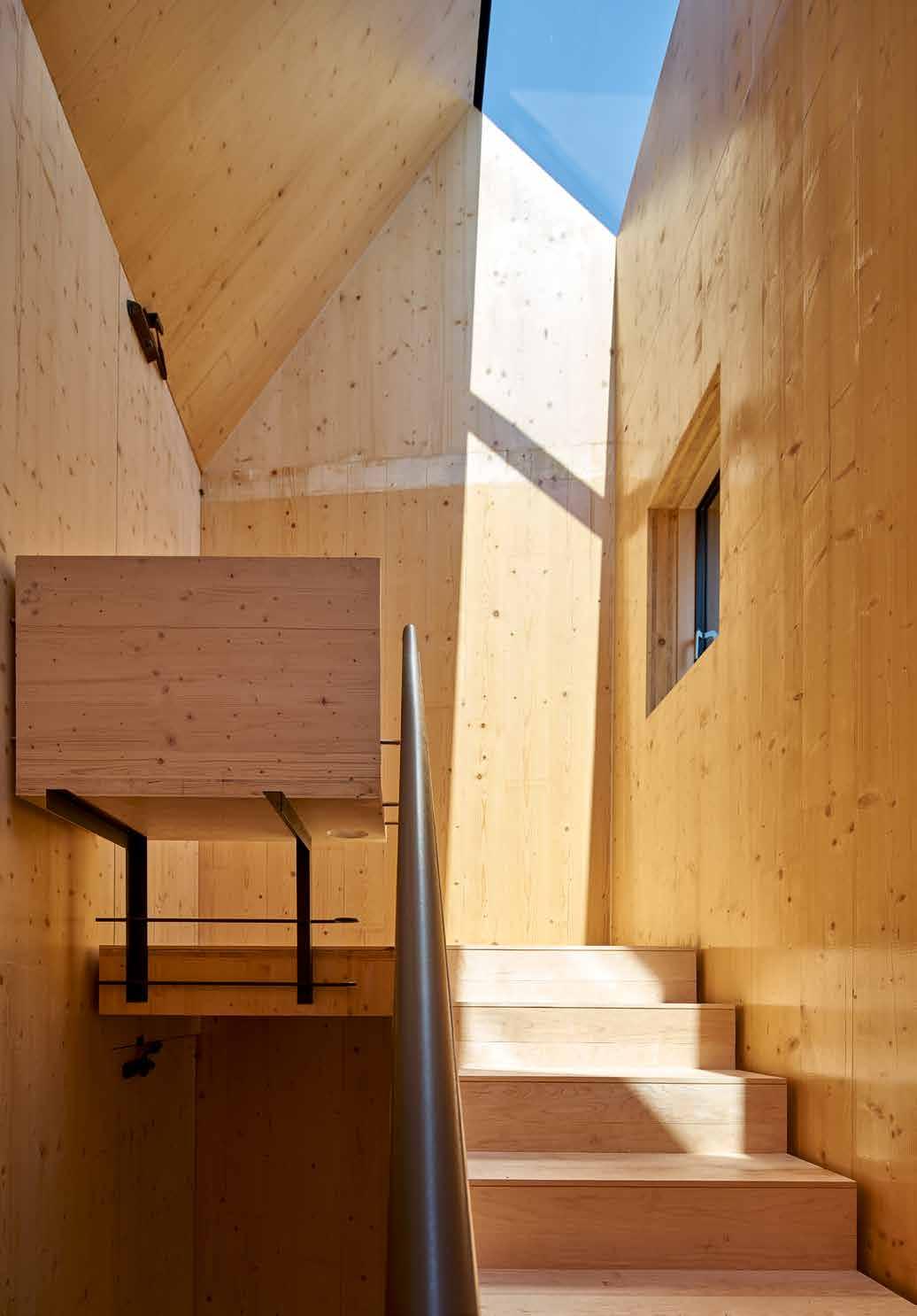
There is a perceived resistance from lenders and insurers to back CLT which can result in clients' reluctance to adopt the material. From the case studies in this book this perception is shown to be false.
The overwhelming feedback from visitors and users of completed CLT structures is highly positive in terms of aesthetic and comfort but also how warm and quiet people find the spaces.
At Woodberry Down, Berkeley Homes have reported fewer overheating events in the common parts, due to the lower thermal mass of the structure, and substantially less movement resulting in reduced cracking to the internal finishes.
A number of formal post-occupancy evaluation studies are now under way which should provide more empirical data to add to the anecdotal evidence.
91
POST COMPLETION Image: Barretts Grove, Groupwork + Amin Taha © Tim Soar
MORTGAGES & SALEABILITY
In the UK, there have been no reported issues in obtaining mortgages for homes constructed from CLT. This includes single family dwellings and midrise multi-home schemes.
Lenders will generally rely on the approval of the Council for Mortgage Lenders (CML) in order to provide mortgages for any particular construction type. The CML in turn wants to see that warranty providers are willing to provide warranties. Lendlease reported that this was their route to satisfying mortgage lenders on behalf of their purchasers; by obtaining approval from the NHBC.
At Murray Grove (pg.178-179), the developer was keen not to overstate the timber structure however the agents reported no reduction in value or desirability in the flats. Indeed, the flats retained their value through the housing downturn of 2009-2012. With more CLT structures being completed and more public knowledge of the material, the quality benefits are more widely appreciated, especially where some CLT is exposed. For many buyers the carbon credentials of the material are also seen as a positive.
92
INSURANCE
As well as there being no reported issues with obtaining insurance cover during construction, there have been no problems with buildings insurance, which is taken out by the building owner and covers the completed property against damage or loss. Lendlease have reported no issues in insuring CLT buildings post completion, and there was no additional premium for insuring a CLT building over other construction types.
BUILDING WARRANTIES
There is often a benefit to developers obtaining a third party, insurancebacked warranty for the completed building from a specialist insurer. These sit above specific product or installation warranties provided by manufacturers or subcontractors and any contractual warranty from consultants. Warranty providers’ standards are extensive and rigorous with reviews of construction details and strategies through the design stages and regular inspections through construction. These largely follow building control guidance, but individual insurers can have specific areas of interest where their requirements exceed the Building Regulations.
Sectors tend to operate differently. New build housing is often sold with a 10 year warranty. The National House Building Council (NHBC) were the first to offer this, and there are now other providers in the UK market. These warranty providers have technical teams with construction industry experience who can engage with the consultants at design stages and help agree solutions that meet their criteria. In this sense CLT is treated no differently to any other ‘non-standard’ construction technology.
NHBC provided a warranty for Murray Grove in 2008; (pg.178-179), their first pilot residential scheme constructed entirely from CLT panels above first floor slab. Whilst they advised that subsequent schemes would still be assessed by them on a case-by-case basis, the details developed and the knowledge obtained has informed their response in subsequent CLT residential projects.
93
MAINTENANCE AND REPAIRS
Where CLT has been damaged, for example by fire or water penetration, repair is possible, either by replacement of the damaged timber or reinforcement of the affected area.
In the first instance, where any damage is encountered, a structural appraisal should be carried out to establish whether urgent action is required to restore stability. Repairs to damaged elements can often be performed by cutting out the effected area and scarfing or splicing in new material. Where the damage is close to a junction, it may be necessary to reinforce the area with steel brackets to ensure robustness.
In cases of severe damage, whole panels may need replacing. In these cases, the surrounding structure should be propped, the panel cut out and a new panel or panels fixed in place.
FIRE
In many CLT structures, the timber provides part of the fire resistance so there is a degree of structural redundancy. In the case of a minor fire, where charring has occurred, it is therefore likely that the load-bearing section of the element is still intact.
In this case it would usually not be necessary to reinforce the structure, however, the fire protection should be restored, either by replacement of the effected timber or by addition of a fire resistant lining. Where larger fires have occurred and one or more structural elements have been severely damaged, it may be possible to remove and replace the entire element.
94
WATER
Long term exposure to high levels of moisture can lead to decay of the timber. Even small amounts of moisture, if allowed to penetrate the timber, can cause detrioration if not allowed to evaporate away, which is why it is essential to ensure the timber is dry before roof membranes are laid.
Where water damage is discovered, it is essential to ensure that all effected areas are identified as water can traverse CLT structures and build up in areas some distance from the original source.
Where long term damage has occured, testing core samples to ensure structural integrity may be a less expensive solution than replacing entire panels.
Once structural integrity has been ensured, all areas should be allowed to dry out before the damage is cut away and replaced through gluing, screwing or nailing additional timber. An engineer will be required to ensure structural integrity.
If the water penetration is a result of an inherent vulnerability, such as in a roof gulley, chemically protecting the repaired timber should be considered.
95
MONITORING AND EVALUATION
Incorporating monitors within the fabric of a CLT building can be useful to measure movement of the structure or moisture levels which can give early warnings of any failures and mitigate issues such as leaks. Moreover, data collected from monitoring devices can help improve our ability to accurately design for key factors such as thermal and acoustic performance, through expanding our as-built database for CLT. Relying on monitors, which tend to be buried behind finishes and therefore not easily maintained, can be a risk if this is the only measure to ensure performance.
Several of the case studies reported a desire to incorporate some form of monitoring however few were implemented.
Data from the select studies currently under way will help us to understand and assess the longer term behavior of CLT in a range of situations.
The Architecture Archive (pg.244-245) is currently undergoing environmental monitoring and, particularly as a pure/solid CLT build up should produce easily extrapolated data on this materials true dynamic performance.
Similarly, at Woodberry Down (pg.218-219), a monitoring program is currently being established for both the CLT case study scheme and an adjacent traditional new-build block, which will aim to generate useful comparative data for designers, covering a number of areas:
Energy Use - comparing the energy used per apartment between the two schemes.
Humidity - testing to what extent the natural hygroscopic performance of CLT regulates the internal humidity, especially in bathrooms. Also to measure whether moisture builds up in the structure or is able to migrate to outside air.
Vibration - measuring the building’s deflection at roof level to compare with the design assumptions. Also monitoring vibration at slab level from live loads.
96
Thermal Performance - taking measurements to monitor the comfort levels within different units and through comparison with the adjacent concrete building, to determine to what extent the timber affects these comfort indicators.
Resident Satisfaction - while there are number of reports of high levels of resident satisfaction in CLT buildings, a formal feedback process will be helpful to benchmarks these..
97
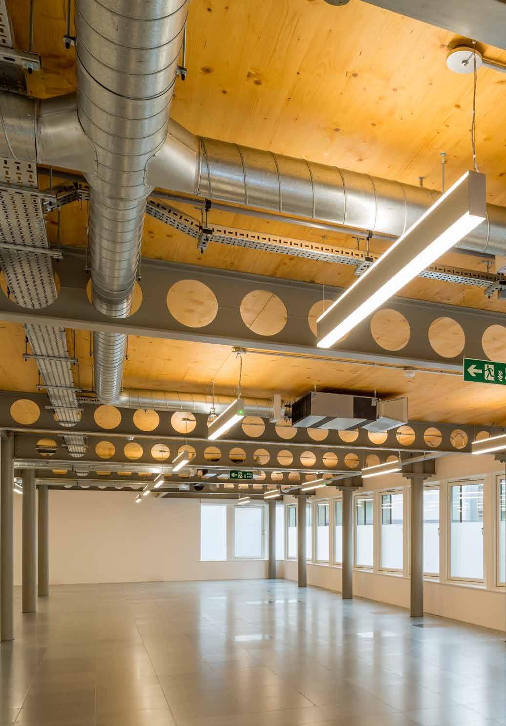
CASE STUDIES
The following section contains the 100 case study projects, categorized into four broad sectors: Residential, Education, Commercial and Public & Civic.
The 100 case studies comprise:
32 Education buildings
Key
32 Residential buildings (13 of which are Private)
15 Commercial buildings
21 Public & Civic buildings
The uneven spread across the sectors is indicative of the tendency to use CLT for certain applications with the vast majority built to date being residential and education buildings.
The embodied carbon figures listed for each project indicate the net carbon saved within the timber superstructure only. This considers both the carbon sequestered in the timber (expressed as negative emissions) and the carbon produced in the manufacture and delivery of the panels. It is important to note that in a full embodied carbon calculation this aspect of the building would only form part of the overall carbon cost of the construction, evaluated alongside the foundations, other structural materials within hybrid schemes, finishes and cladding, however to indicate the significance of the timber itself we have focused on this aspect alone.
The above ground structures have been categorized as ‘Pure CLT’ (CLT alone), ‘Pure Timber’ (CLT combined with other timber elements such as glulam), or ‘Hybrid’ (CLT combined with other structural materials such as steel or concrete). These categories give an indication of the significance of the timber’s carbon savings as in ‘Hybrid’ schemes the emissions from steel/ concrete will also have an impact.
Some carbon savings quoted for engineered timber structures include the mitigated carbon that would have been emitted were the same scheme to have been built traditionally. Whilst this saving is very real and does affect overall carbon emissions from the industry it was not possible to confidently quote this for all schemes without complex structural analysis. Image: Curtain Place, Waugh Thistleton
99
Architects © Ben Clarkson Commercial Educational Public/Civic Residential
Key Commercial Educational Public/Civic Residential
Key Commercial Educational Public/Civic Residential KeyCommercial Educational Public/Civic Residential
100 CONTENTS EDUCATION 103 Archway Early Years Centre 105 Kingsdale School, Music and Sports 107 Cranleigh School 109 City of London Academy Islington 111 West Buckland School 113 The Open Academy 115 Tring Park School for performing arts 117 Lauriston Primary School 119 Sandal Magna School 121 Holy Trinity Primary School 123 Passmores Academy 125 Waingels College 127 Hereford College of Arts Hub 129 Hayes Primary School 131 Hilden Grange Prepatory School 133 The Lee Centre 135 Ickburgh School 137 Arcadia Nursery 139 William Perkin Church of England School 141 ARK Brunel Primary Academy 143 Alfriston School Swimming Pool 145 Mayfield School 147 Mossbourne Victoria Park Academy 149 Graveney Sixth Form 151 Essex University Business School 153 Davenies Boys Prepatory School 155 Wynch Cottage 157 GSK Centre for Sustainable Chemistry 159 Alconbury Weald Primary School 161 Oculus Teaching Building 163 SGS Berkeley Green 165 Ely Boathouse 167 RESIDENTIAL 169 Carlisle Lane 171 Fairmule House 173 Sunken House / Ed’s Shed 175 Cavendish Avenue 177 Stadthaus/Murray Grove 179 Hunsett Mill 181 Russell Street 183 Strange House 185 Watson House 187 Dune House 189 Bridport House 191 Whitmore Road 193 Woodblock House 195 Sussex House 197 Mazarin House 199 Nurses Cottage 201 Kingsgate House 203 Wenlock Cross 205
101 Barretts Grove 207 142 Bermondsey Street 209 Trafalgar Place 211 Cobalt Place 213 St Clare’s College 215 Lansdowne Drive Passivhaus 217 Woodberry Down 219 Hurdle House 221 Cowan Court 223 UEA Blackdale 225 Bacton Low Rise (Phase 1) 227 Dalston Works 229 Carmarthen House 231 Pitfield Street 233 COMMERCIAL 235 The Office 237 Bedfont Lakes Pavilion 239 Woodland Trust Headquarters 241 Alex Monroe Studio 243 Architecture Archive 245 Sky Believe in Better Building 247 Crosslam Workshops 249 Sky Health and Fitness Centre 251 Curtain Place 253 Christies Care Office Building 255 De Beauvoir 257 Lower James Street 259 Vitsoe Headquarters 261 Wildernesse Restaurant 263 National Automotive Innovation Centre 265 PUBLIC & CIVIC 267 MK40 Tower 269 Lumen Reform Church 271 The Garden Museum 273 John Hope Gateway 275 The Termite Pavilion 277 Royal Shakespeare Theatre 279 Dyson Centre for Neonatal Care 281 Tower of Love 283 The Hive 285 Victoria Leisure Centre 287 Regents Park Open Air Theatre 289 Youth Leisure Zone 291 Ditchling Musuem of Art and Craft 293 Olympic Park Timber Lodge 295 Glowing Orchard 297 Maggie’s Centre 299 Frampton Park Baptist Church 301 Chatham Command of the Oceans 303 Visitor Centre, Hastings Pier 305 Belarusian Memorial Chapel 307 The Gateway Buildings 309 TIMELINE 310

EDUCATION
Education has remained one of the most popular sectors for CLT structural solutions, with some of the first CLT buildings in the UK being schools. Most school refurbishments, extensions and expansions require that schools remain open during the construction. Such building projects require minimal distractions and maximum safety, and tend to need to be completed within an academic year. The primary benefits of a reduced construction program and a cleaner, safer, quieter site offered by CLT can therefore provide the ideal solution.
Education buildings are typically low rise and include a mix of large open span spaces for assembly areas, halls and auditoriums alongside smaller cellular classrooms. This combination tends to result in the use of hybrid structures, where pure CLT is used for the classrooms and glulam or steel additions are only necessary for the wide span spaces.
In addition to these practical benefits, research has shown that exposed timber interiors have a calming effect on children which promotes better learning. Additionally, exposing the structure allows its use as an educational tool helping the children to learn about construction within their curriculum. Exposing the timber in educational buildings is generally quite straightforward due to the pre-existing requirement for a thorough fire safety strategy that ensures very quick and easy evacuation from these typically low-rise buildings. CLT continues to be widely used in education buildings and is increasingly popular with councils and the Education Funding Agency who continue to champion the use of CLT in construction. Image:
103
Graveney Sixth Form, Urban Projects Bureau © Killian O’Sullivan
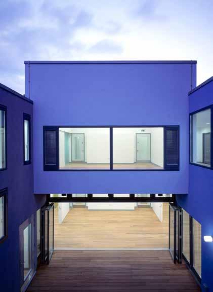

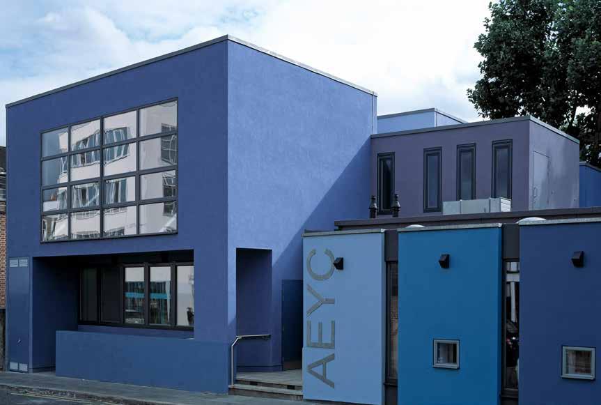
104
© Edmund Summner
LOCATION
London Borough of Islington
HEIGHT / STOREYS
21 ft (6.4 m) / 2 storeys
CONSTRUCTION COST
£1 million
ARCHITECT
Kay Hartmann Architects
STRUCTURAL ENGINEER
Fluid Structures
TIMBER ENGINEER
KLH UK / Techniker
TIMBER CONTRACTOR
KLH UK
TIMBER MANUFACTURER
KLH Massivholz
MAIN CONTRACTOR
Durkan Pudelek
TIMBER VOLUME
4,600 ft 3 (132 m 3)
TIMBER ASSEMBLY
2 weeks
OVERALL CONSTRUCTION
46 weeks
STRUCTURE TYPE
Pure CLT
EMBODIED CARBON WITHIN TIMBER*
-80 tons (-72 tonnes) CO 2 e
CLT FACT
Made financially viable by reducing costly foundations
Council
The objective was to create a welcoming and stimulating creative environment to provide childcare and education for babies and children from 6 months to 5 years, alongside a wide range of health and family support services.
The new building is made up of a differentiated and interconnected series of spaces of varying heights and widths, which complement the surroundings and maintain the scale of the existing facilities. Spaces were designed to accommodate specific functions resulting in differing widths and sizes. The ‘public’ functions such as kindergarten and parent’s areas are housed on the ground floor with the upper storey providing a home for the support services.
CLT presented itself as the most logical solution to building on this tight inner London site. The aim was to complete the superstructure as quickly as possible, limiting the number of site deliveries to reduce the impact on both the adjacent nursery, that had to be kept open during the construction period, and bus depot.
One of the first CLT buildings in the UK, this scheme set a precedent and encouraged the uptake of CLT.

105
2006
Education
Islington
ARCHWAY EARLY YEARS CENTRE
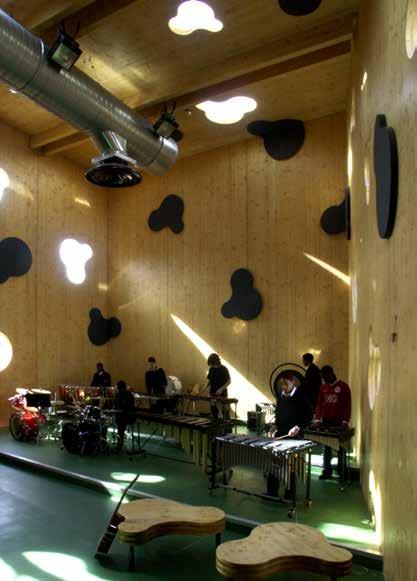
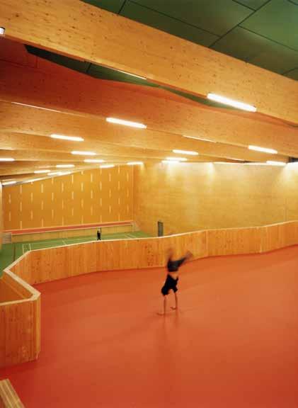
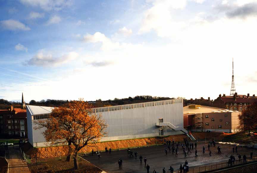
106
© Alex de Rijke / dRMM
LOCATION
London Borough of Southwark
HEIGHT / STOREYS
49 ft (15 m) / 2 storeys
CONSTRUCTION COST
£3.4 million
ARCHITECT
dRMM
STRUCTURAL ENGINEER
Michael Hadi Associates
TIMBER ENGINEER
Michael Hadi Associates / KLH UK
TIMBER CONTRACTOR
KLH UK
TIMBER MANUFACTURER
KLH Massivholz
MAIN CONTRACTOR
Galliford Try
TIMBER VOLUME
29,900 ft 3 (848 m 3)
TIMBER ASSEMBLY
4 weeks
OVERALL CONSTRUCTION
52 weeks
STRUCTURE TYPE
Pure Timber
EMBODIED CARBON WITHIN TIMBER*
-521 tons (-472 tonnes) CO 2 e
CLT FACT
The first publicly funded CLT building in the UK
KINGSDALE SCHOOL, MUSIC AND SPORTS
Education Southwark Council
Sports halls are essentialy very large, high spatial volumes of space, defined by pitch layouts. They tend to have blank internal walls that offer re-bound surfaces. Addressing the design challenge of turning a generic low-budget box into daylit and expressive architecture offering maximum flexibility for different user-groups, dRMM developed a hyperbolic parabolic roof from progressively rotated glulam beams infilled with thin CLT. Loadbearing CLT walls support the roof while daylight floods into the hall through high-level glazing. A freestanding CLT ‘building within a building’ provides changing rooms and storage space, while the dance space created on the mezzanine lends further flexibility.
In contrast, an angular form was required for the Music Block to manage acoustic reverberation. Full-height floor-to-roof CLT panels, mounted vertically, form the external walls and carry the CLT roof panels, which are reinforced with timber ribs. The outer walls are ‘perforated’ with free-form window apertures, with the cut out pieces used as furniture – thoughtful design minimizing wasted material.
In both spaces the CLT provides both structure and internal finish requiring only external insulation and profiled weatherproof cladding.
107
2007
Section
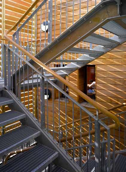
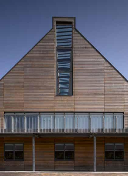
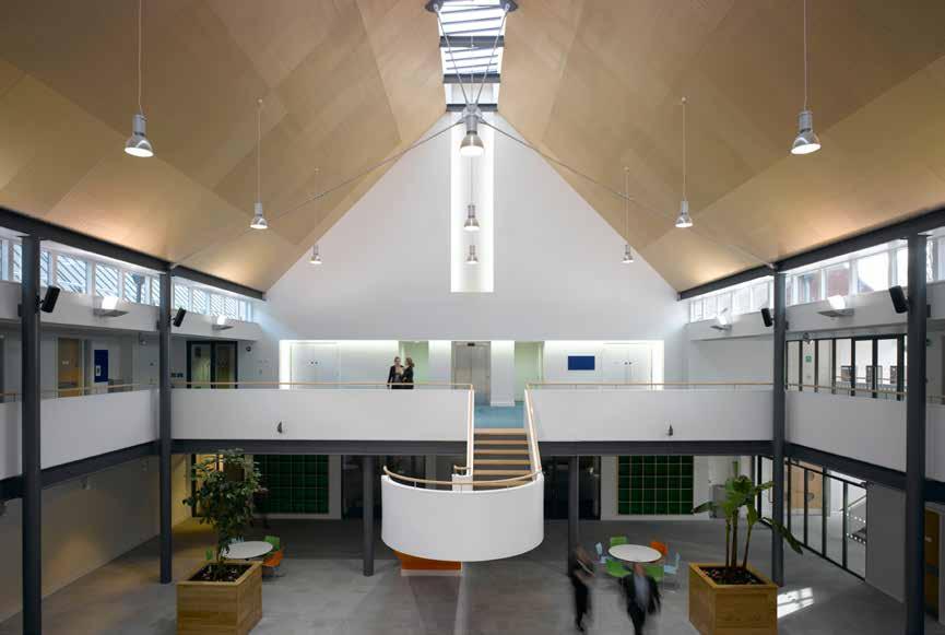
108
© Edmund Sumner
LOCATION
Cranleigh, Surrey
49 ft (15 m) / 2 storeys
CONSTRUCTION COST
£7 million
HEIGHT / STOREYS ARCHITECT
Pringle Richards Sharratt
STRUCTURAL ENGINEER
This first phase of the redevelopment masterplan of Cranleigh School comprises almost 40,000ft 2 of science laboratories, classrooms and a lecture theatre.
The building is organized around a covered central court, which functions as the heart of the building. The larger science laboratories are accommodated at ground level with additional science spaces, classrooms and lecture theatre on the upper level.
The ground floor science laboratories define the structural grid and are built as large permanent spaces. At first floor, lightweight acoustic partitions and a raised access floor allow flexibility for future arrangements.
TIMBER ENGINEER
KLH UK / Techniker / Thomasons Thomasons
KLH UK
TIMBER MANUFACTURER
KLH Massivholz
MAIN CONTRACTOR
TIMBER VOLUME
9,900 ft 3 (279 m 3)
TIMBER ASSEMBLY
5.5 weeks
OVERALL CONSTRUCTION
78 weeks
Classically pitched roofs, covered in patinated standing seam zinc, sit comfortably with the surrounding 19th century school buildings and the countryside beyond. Glazing along the apex of the pitched roof floods the hall with natural light. On the exterior, a variety of hand-made English bond brickwork and cedar cladding create a texture that is simultaneously traditional and contemporary.
The walls and roofs were constructed from CLT. While the cost was found to be comparable to steel this approach resulted in a quicker build and earlier achievement of weather tightness. CLT proved to be an expedient, economic and environmentally friendly way to achieve the architectural concept.
STRUCTURE TYPE
TIMBER CONTRACTOR Hybrid R Durtnell & Sons
EMBODIED CARBON WITHIN TIMBER*
-168 tons (-152 tonnes) CO 2 e
CLT FACT
Quicker achievement of weather tightness
109
Section
2009
Cranleigh School CRANLEIGH SCHOOL Education
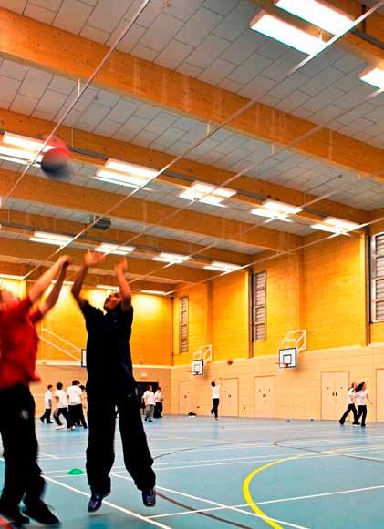

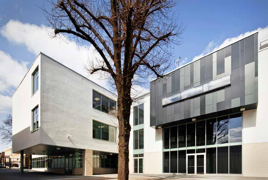
110
© Graham Ackroyd
LOCATION
London Borough of Islington
HEIGHT / STOREYS
39 ft (12 m) / 3 storeys
CONSTRUCTION COST
£28 million
ARCHITECT
Aukette Swanke
STRUCTURAL ENGINEER
BuroHappold Engineering
TIMBER ENGINEER
KLH UK
TIMBER CONTRACTOR
KLH UK
TIMBER MANUFACTURER
KLH Massivholz
MAIN CONTRACTOR
Galliford Try
TIMBER VOLUME
8,000 ft 3 (226 m 3)
TIMBER ASSEMBLY
CITY OF LONDON ACADEMY ISLINGTON
Department of Education / City of London / City University
This new school replaces Islington Green School, made famous by the Pink Floyd hit Another Brick in the Wall which was sung by pupils from the 1979 fourth form music class. Transforming this existing 1960s secondary school into a brand new facility for 850 pupils, the new building integrates a refurbished Victorian primary school for pupils with severe special needs encouraging shared social and learning experiences. The 87,000ft² building was delivered in phases to enable the school to remain operational during construction.
Responding sympathetically to the context and scale of the surrounding area the academy is organized around an internal atrium. This central adaptable multipurpose learning and assembly area can be opened to an adjacent drama hall and external courtyard. Roof lights provide the space with good quality natural lighting and ventilation.
Sustainable construction was a key consideration in material selection with off-site fabrication used to reduce waste and packaging. Protection of existing trees and the provision of green roofs, which also attenuate rainwater run-off, help achieve biodiversity targets while 20% renewable energy is generated through the use of photovoltaic cells and a wood-pellet biomass boiler.
OVERALL CONSTRUCTION
122 weeks
STRUCTURE TYPE
Hybrid
EMBODIED CARBON WITHIN TIMBER*
-146 tons (-132 tonnes) CO 2 e 2 weeks
CLT FACT
Using timber for phase 1 unlocked the site without delaying the program
111
Section Education
2010

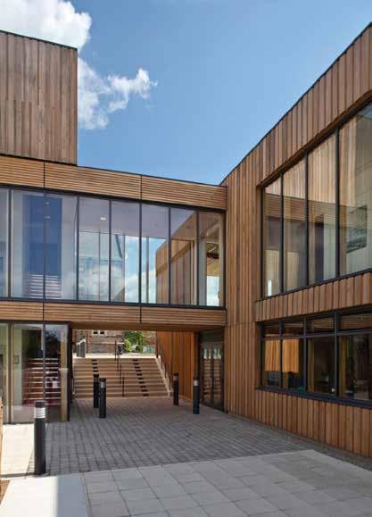
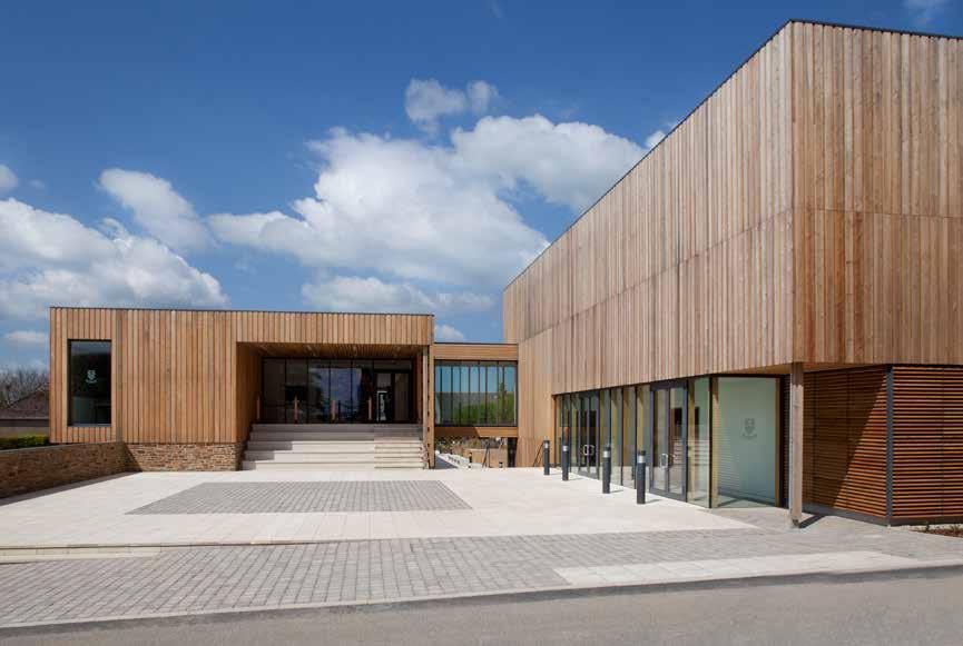
112
© Paul McCarthy
WEST BUCKLAND SCHOOL
West Buckland School
LOCATION
Barnstaple, Devon
34 ft (10.4 m) / 2 storeys
CONSTRUCTION COST
£3.25 million
HEIGHT / STOREYS ARCHITECT
Rundell Associates
STRUCTURAL ENGINEER
Atelier One
TIMBER ENGINEER
Atelier One
TIMBER CONTRACTOR
TIMBER MANUFACTURER
KLH Massivholz
MAIN CONTRACTOR
The new centre for Art and Design at the West Buckland School is an extension to the existing Victorian schoolhouse. From the outset it was envisaged that the new buildings would create a hub within the campusvisually, physically and socially linking the new and old buildings.
The building is comprised of two staggered blocks clad in larch and locally sourced stone. A number of covered and internal routes across the site reinforce the connection between the prep and upper school and a glazed bridge provides a gallery that can be viewed from outside whilst allowing for sweeping views across the Devon countryside from within.
Particular importance was given to natural lighting in the classrooms and studios, with skylights and full height windows flooding light into the interior.
Environmental credentials were a key driver in the design decisions. The entire structure, including lift shafts, is made of CLT panels and glulam beams. The large format panels reduced the number of construction joints and as such the potential for air leakage. The use of CLT also allowed for the development of simple façade details.
TIMBER VOLUME
14,300 ft 3 (404 m 3)
TIMBER ASSEMBLY
5 weeks
OVERALL CONSTRUCTION
58 weeks
A heated wood pellet boiler and an array of photovoltaic cells work with a Building Management System to optimize the building’s energy use keeping its operational energy demand impressively low.
STRUCTURE TYPE
EMBODIED CARBON WITHIN TIMBER*
CLT FACT
Pearce Construction Pure Timber Excellent
113
3.18 m 3(m
airtightness of
2/h) @ 50 Pa
First Floor Plan
KLH UK -252 tons (-228 tonnes) CO 2 e
2010 Education
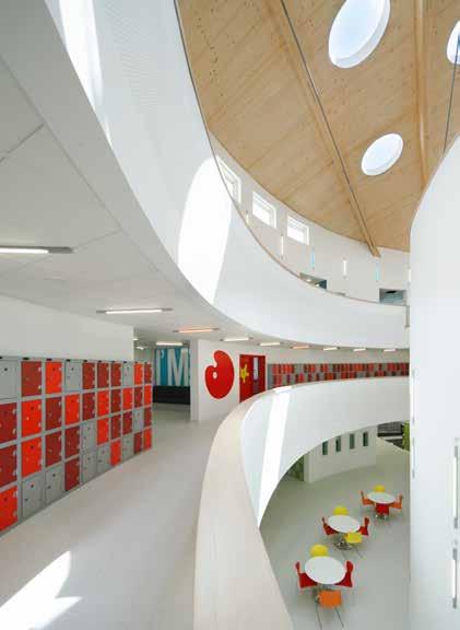


114
© Hufton + Crow
Education
THE OPEN ACADEMY
Norfolk Council / Diocese of Norwich / Open Trust
LOCATION
Norwich, Norfolk
59 ft (18 m) / 3 storeys
CONSTRUCTION COST
£17 million
HEIGHT / STOREYS ARCHITECT
Sheppard Robson
STRUCTURAL ENGINEER
Ramboll
TIMBER ENGINEER
KLH UK
TIMBER CONTRACTOR
The unique and innovative cyclical plan takes its inspiration from the aeronautical history of the site. The main building is a series of three concentric bands, which provides dual aspect to this new school. The outer band houses the main teaching accommodation; the second band provides the ancillary spaces such as store-rooms and offices, and the inner band is the main circulation route, stacked as a series of open balconies that wrap around the central forum: a multi-functional social and learning space that includes a lecture theatre. Extending horizontally from the rotunda structure is a rectangular sports hall.
TIMBER MANUFACTURER
KLH Massivholz
MAIN CONTRACTOR
The school is constructed predominantly from load-bearing CLT. The structural layout for the main building is an annular arrangement of loadbearing walls that offers considerable flexibility for planning the internal space. The 9 inch floor panels span 25 feet with uninterrupted soffits. Glulam downstand beams are used where spans exceed this. Where the perimeter walls step back, glulam beams transfer the upper storey loads into the wall.
TIMBER VOLUME
123,600 ft 3 (3,500 m 3)
TIMBER ASSEMBLY
Crowning the central forum is a gently curving roof formed from laminated timber panels that are supported by 12 canted glulam arches. Circular rooflights punch through the timber soffit to animate the heart of the Academy. Interior and exterior finishes express and celebrate the extensive use of timber.
STRUCTURE TYPE
OVERALL CONSTRUCTION Hybrid Kier
EMBODIED CARBON WITHIN TIMBER*
KLH UK 65 weeks 18 weeks -2,172 tons (-1,970 tonnes) CO 2 e
CLT FACT
The main contractor estimated a 14-18 week time saving overall
115
2010
First Floor Plan

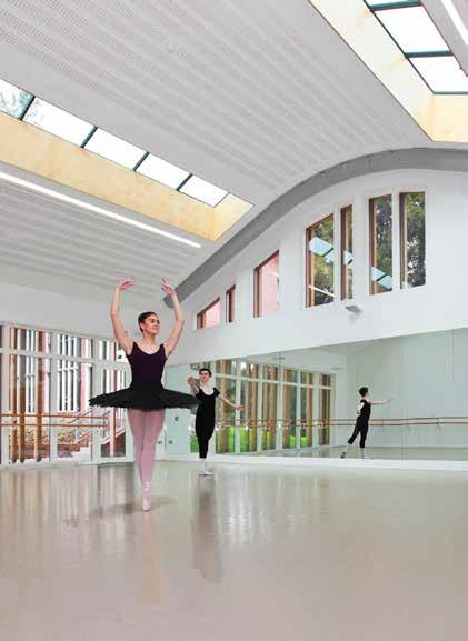
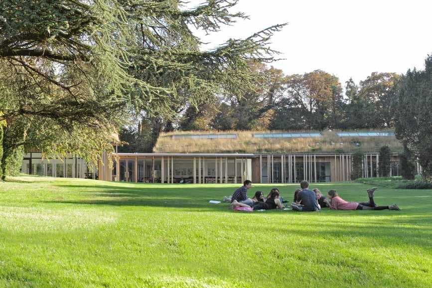
116
© Mark Foley / Burrell Foley Fischer
© Gentle Vision Photography
© Mark Foley / Burrell Foley Fischer
TRING PARK SCHOOL FOR PERFORMING ARTS
Tring Park School for Performing Arts
LOCATION
Tring, Hertfordshire
22 ft (6.6 m) / 1 storey
CONSTRUCTION COST
£2.04 million
HEIGHT / STOREYS ARCHITECT
Burrell Foley Fischer
STRUCTURAL ENGINEER
Price & Myers
TIMBER ENGINEER
Price & Myers
TIMBER CONTRACTOR
TIMBER MANUFACTURER
Schilliger Holz
MAIN CONTRACTOR
Ashe Construction
TIMBER VOLUME
10,600 ft 3 (300 m 3)
TIMBER ASSEMBLY
6.5 weeks
OVERALL CONSTRUCTION
36 weeks
Dance presents an extremely demanding set of environmental conditions in which to train, practice and present the art form effectively. Dancers are highly susceptible to cold and drafts, yet the moisture-laden atmosphere of a studio after an intensive class can be overwhelming. In response to these conditions, prefabricated, precision-engineered structural timber wall and roof panels were selected for the design of five new dance studios set within the grounds of a Grade II listed building.
Rooted in the site’s natural setting the building takes a holistic approach to the environmental conditions related to dancers’ specific needs. The internal heights of the dance studios reach 20 feet at their curved apex reducing to 13 feet towards the eaves. Externally, the eaves are kept intentionally low to reduce the profile of the building while the curved apex and wild flower meadow roof sensitively soften the building into the landscape.
STRUCTURE TYPE
Pure Timber
EMBODIED CARBON WITHIN TIMBER*
-188 tons (-171 tonnes) CO 2 e
CLT FACT
CLT chosen for warmth and moisture regulation essential for dance
Eurban Ground
The timber is exposed internally, painted with a white wash to provide a light internal surface that is warm to the touch. The building is naturally ventilated for a large proportion of the year through opening roof lights and perimeter ventilation, with low velocity mechanical ventilation used at other times.
117
Floor Plan
2010
Education
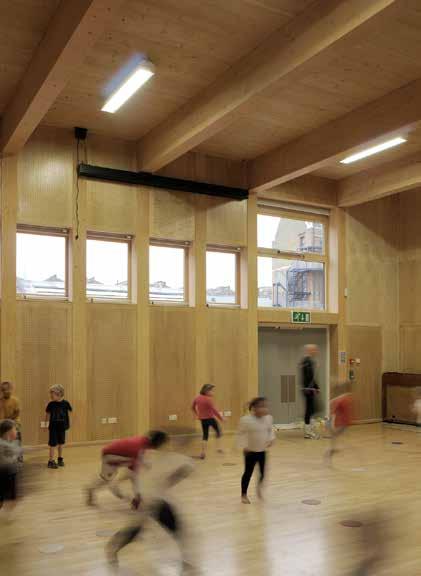
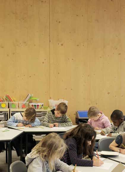
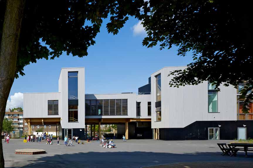
118
© Tim Soar
© David Grandorge © Tim Soar
LOCATION
London Borough of Hackney
HEIGHT / STOREYS
40 ft (12.2 m) / 3 storeys
CONSTRUCTION COST
£8.3 million
ARCHITECT
Meadowcroft Griffin Architects
STRUCTURAL ENGINEER
Price & Myers
TIMBER ENGINEER
KLH UK
TIMBER CONTRACTOR
KLH UK
TIMBER MANUFACTURER
KLH Massivholz
MAIN CONTRACTOR
Neilcott Construction
TIMBER VOLUME
23,000 ft 3 (651 m 3)
TIMBER ASSEMBLY
14 weeks
OVERALL CONSTRUCTION
Phase 1 - 45 weeks
Phase 2 - 38 weeks
LAURISTON PRIMARY SCHOOL
Hackney Council
The objective of the project was to increase the capacity of an existing primary school while enabling the school to remain open. A multi-storey building with a large undercroft was designed, which increased both the internal area of the school and the amount of external play space on the site. It also gave the school a covered external play area that it didn’t previously have.
A phased design was essential to this project as the existing school had to remain in operation during construction. The largest, three-storey section of the plan was constructed first so as to accommodate the existing school in addition to the classes of the incoming year. The second phase was then constructed in place of the original school building after its demolition.
Disruption to the school was minimized through the extensive use of prefabricated elements that reduced both the overall site period and the noise and dust created during construction. CLT was the obvious structural solution as panels are quick to assemble and is a relatively quiet construction process.
The CLT is left exposed providing an internal environment that offers visual warmth and texture.
STRUCTURE TYPE
Pure CLT
EMBODIED CARBON WITHIN TIMBER*
-388 tons (-352 tonnes) CO 2 e
CLT FACT
Using CLT allowed the school to remain open during the construction
119
Section
2010 Education
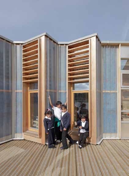
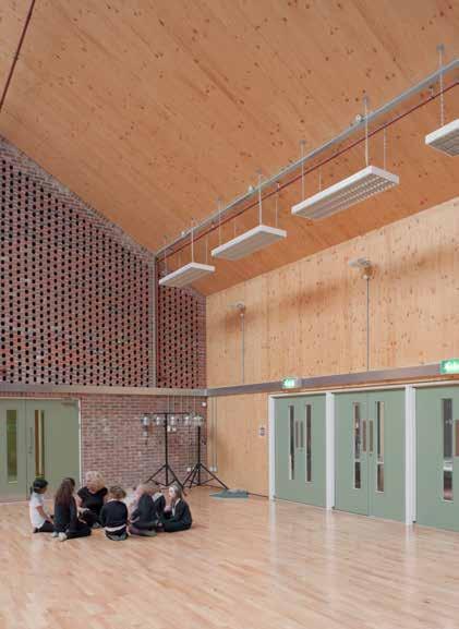
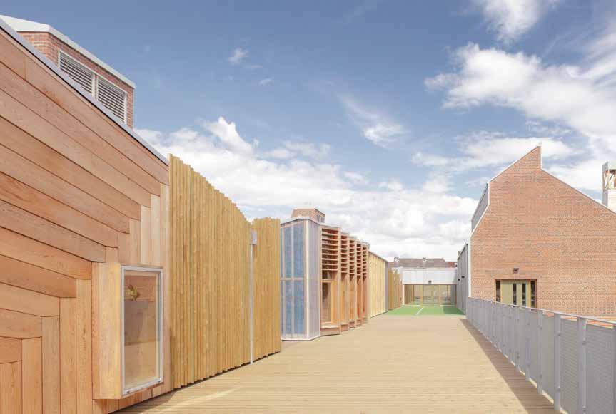
120
© Mark Hadden
Education
SANDAL MAGNA SCHOOL
Wakefield Council
LOCATION
Wakefield, West Yorkshire
HEIGHT / STOREYS
13 - 38 ft (4 - 11.7 m) / 1 storey
CONSTRUCTION COST
£5.8 million
STRUCTURAL ENGINEER ARCHITECT
Sarah Wigglesworth Architects
Replacing an existing school deemed no longer fit for purpose, the design takes its cue from its immediate context, and is laid out as three parallel single storey wings that reference the neighboring terraced frontages and irregular back streets. A red brick is used extensively across the façade to emulate the local vernacular, and ventilation stacks above the teaching block echo the silhouette of the adjacent Victorian terraces. The school is crowned by a striking new bell tower that re-houses the original school bell and evokes the tall chimneys of Wakefield’s industrial heritage.
TIMBER ENGINEER
KLH UK Techniker
TIMBER CONTRACTOR
KLH UK
TIMBER MANUFACTURER
KLH Massivholz
MAIN CONTRACTOR
A hybrid solution of CLT and load-bearing masonry was developed for the project with locally sourced bricks used for thermal mass. Exposed CLT with surface mounted services reflect the client’s desire to reveal the mechanics of the building for educational purposes, making the building a demonstrative tool to form part of the curriculum for learning about sustainable construction and functionality. CLT compared favourably on price and improved the speed of construction. Chosen for its low embodied carbon, exposed CLT creates a sense of wellbeing within the interior.
TIMBER VOLUME
12,100 ft 3 (343 m 3)
TIMBER ASSEMBLY
8 weeks
OVERALL CONSTRUCTION
80 weeks
The new building accommodates 210 pupils aged between 5-11 years alongside kindergarten provision for 26 children. The school also contains a community room for use by parents for adult education and other activities. It has been designed to permit expansion in the future to a 315 place school.
STRUCTURE TYPE
Allenbuild Hybrid
EMBODIED CARBON WITHIN TIMBER*
-209 tons (-190 tonnes) CO 2 e
CLT FACT
CLT hybrid with load bearing masonry for thermal mass
121
2010
Library Window Detail
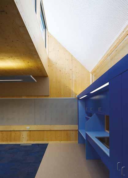
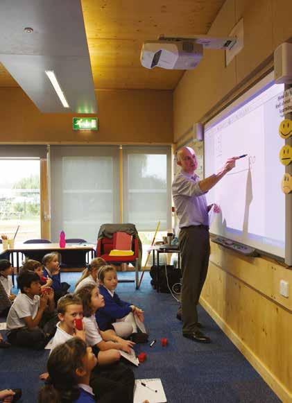

122
© Leigh Simpson Photography
LOCATION
London Borough of Richmond upon Thames
HEIGHT / STOREYS
18 ft (5.5 m) / 1 storey
CONSTRUCTION COST
£4.7 million
ARCHITECT
Architype
STRUCTURAL ENGINEER
HOLY TRINITY PRIMARY SCHOOL
The brief was to expand and refurbish an existing 1970s primary school to increase its capacity from 210 to 420 pupils. With the school’s ethos very much at the centre of the design, consultation with the school children provided invaluable insights.
TIMBER ENGINEER
TIMBER CONTRACTOR
B & K Structures
TIMBER MANUFACTURER
Binderholz
MAIN CONTRACTOR
Apollo Group Techniker
TIMBER VOLUME
33,200 ft 3 (940 m 3)
TIMBER ASSEMBLY
12 weeks
OVERALL CONSTRUCTION
60 weeks Techniker
Four new ‘green’ wings provide 11 classrooms, 2 shared resource areas, a new staff block, and additional circulation space. A new entrance leads through to a suite of classrooms and group spaces that open out into the landscape. The new wings connect lightly to the refurbished existing structure to maximize future flexibility, and create a signature visual form for the new school. Circulation has been rationalized and the hall is now the central ‘heart’ of the school around which a lively circulation space branches off into learning and social spaces.
The environmental agenda of the school is manifested in the new, highly energy efficient buildings which were built with CLT. A green roof system helps to acoustically insulate the building from high levels of aircraft noise and a natural, expressive material palette gives the school a warm, rich, tactile and neutral environment.
STRUCTURE TYPE
Pure Timber
EMBODIED CARBON WITHIN TIMBER*
-585 tons (-531 tonnes) CO 2 e
CLT FACT
CLT chosen for green eco wings due to sustainability credentials
Occupied throughout the whole process, a careful solution removed the need for temporary accommodation and reduced disruption. Ground
123
2011
Education
Plan
Floor
Richmond Council
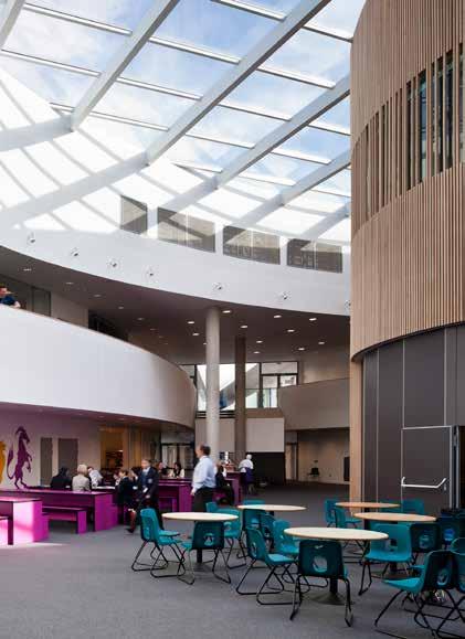
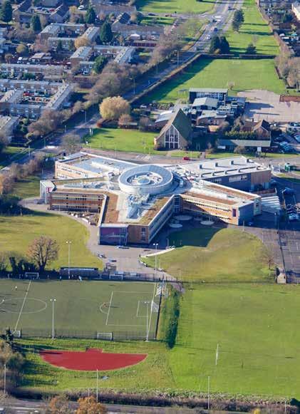
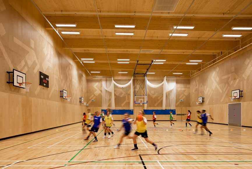
124
© Tim Crocker
PASSMORES ACADEMY
LOCATION
Harlow, Essex
29 ft (8.7 m) / 1 storey
CONSTRUCTION COST
£22 million
HEIGHT / STOREYS ARCHITECT
Jestico + Whiles
STRUCTURAL ENGINEER
AECOM
TIMBER ENGINEER
AECOM / Eurban
TIMBER CONTRACTOR
Eurban
TIMBER MANUFACTURER
Stora Enso
MAIN CONTRACTOR
Passmores Academy, completed in 2011 for Essex County Council, accommodates 1200 students in six learning areas. Formulated around a radial plan, it was built with a communal gathering area or ‘heartspace’ at its centre, which comprises the main assembly halls, from which the rest of the school and adjoining faculty wings radiate outwards.
The sports hall is constructed as a hybrid lean-to arrangement, with CLT used on the two external walls, and a reinforced concrete frame on the two sides adjoining the main structure. Internally, the hall is lined on four sides with plywood to give a consistent appearance, with the CLT exposed at soffit level. CLT was chosen for the sports hall due to its ability to create the volume required, its speed compared with alternative materials and it’s warm appearance. The successful use of CLT for this element of the scheme, its ease of design and assembly, directly influenced the architect’s knowledge of CLT that they were then able to apply for an entire school structure a few years later.
TIMBER VOLUME
3,900 ft 3 (110 m 3)
TIMBER ASSEMBLY
3 weeks
OVERALL CONSTRUCTION
74 weeks
The architect responded to the client’s emphasis on sustainability through natural ventilation systems and biomass boilers for heating. The façade is predominantly clad in timber, incorporating a brown roof and nighttime cooling. Passmores was classed by the Essex Design Initiative as an ‘Exemplar project’.
STRUCTURE TYPE
Willmott Dixon Hybrid
EMBODIED CARBON WITHIN TIMBER*
-67 tons (-61 tonnes) CO 2 e
CLT FACT
Successful use of CLT alongside concrete frame and steel frame elements
Ground Floor Plan
125
2011
Essex County Council
Education
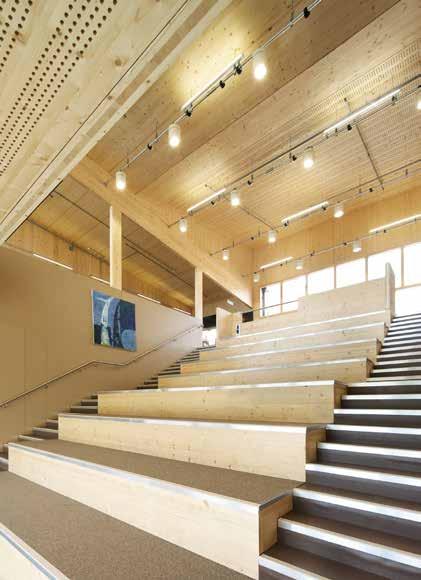
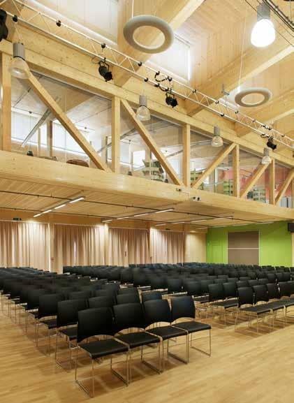
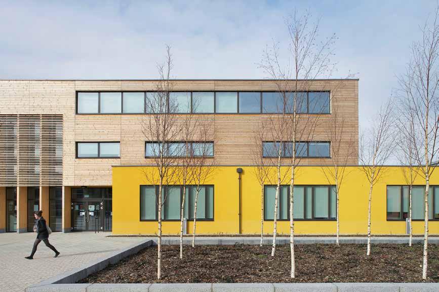
126
© Hufton + Crow
LOCATION
Reading, Berkshire
HEIGHT / STOREYS
32 ft (9.9 m) / 2 storeys
CONSTRUCTION COST
£27 million
ARCHITECT
Sheppard Robson
STRUCTURAL ENGINEER
Ramboll / Eurban
TIMBER ENGINEER
Eurban
TIMBER CONTRACTOR
Education
WAINGELS COLLEGE
Wokingham Borough Council
Driven by the concept of the school as a community and its buildings as a village of learning spaces, Waingels College comprises four separate buildings which frame a planted courtyard: a village green.
Three of the buildings are pastoral bases, while the fourth houses large, shared, communal spaces such as the assembly and dining halls.
Each of the teaching blocks contains flexible, open-plan spaces on the ground floor, with more formal, private classrooms on the upper storeys. Large central staircases double as seating to provide an intimate, central forum within each individual learning community. Avoiding long dark corridors, spaces are naturally lit with interconnected breakout areas encouraging cross-curricular interaction.
All four blocks are built using CLT and glulam. Ceilings, floors and walls are structural and the timber is exposed throughout to create a warm and inviting environment.
TIMBER MANUFACTURER
Schilliger Holz
MAIN CONTRACTOR
Willmott Dixon
TIMBER VOLUME
196,300 ft 3 (5,560 m 3)
With no building permitted on the playing field the new buildings had to be multi-phased around the existing school. The tight nature of the site resulted in new buildings being constructed only 10ft away from operational classrooms. The use of timber meant that the panels could be lifted quickly, minimizing disruption in teaching areas.
Blocks A,B & D - 26 weeks. C - 10 weeks
Eurban 135 weeks
OVERALL CONSTRUCTION
STRUCTURE TYPE
TIMBER ASSEMBLY Pure Timber
EMBODIED CARBON WITHIN TIMBER*
-3,514 tons (-3,188 tonnes) CO 2 e
CLT FACT
Construction 10ft from operational classrooms made possible
127
2011 Ground Floor Plan
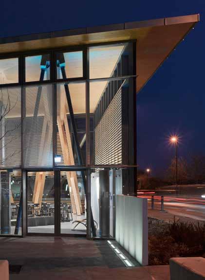
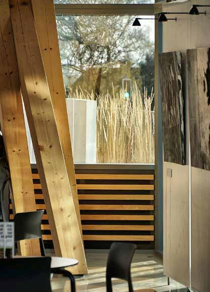
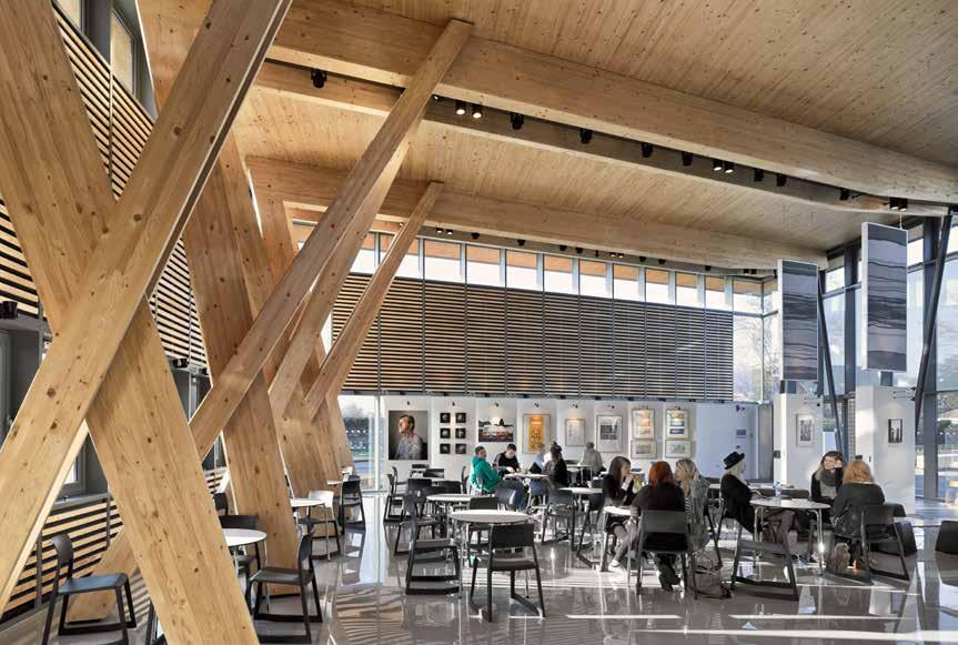
128
© Lance McNulty
© Paul Younger © Lance McNulty
LOCATION
Hereford, Herefordshire
HEIGHT / STOREYS
24 ft (7.2 m) / 1 storey
CONSTRUCTION COST
£920,000
ARCHITECT
Hewitt Studios
STRUCTURAL ENGINEER
Integral Engineering Design
TIMBER ENGINEER
Integral Engineering Design
TIMBER CONTRACTOR
Eurban
TIMBER MANUFACTURER
Schilliger Holz
MAIN CONTRACTOR
Education
HEREFORD COLLEGE OF ARTS HUB
Hereford College of Arts Hub
Conceived as timber from the outset the project provides café and exhibition space in which college staff and students can come together to display and celebrate their work.
Derived from the constraints of the site, the parallelogram ‘wedge’ of the main cafe/exhibition area responds to the geometry of Folly Lane, the double height volume matching the scale of the existing buildings.
The distinctive main volume is an elegant glass box protected from the weather by an oversailing roof. Solid elements within the façade shield from the low sun whilst also providing insulation. The ‘twisted-trestle’ structure is made from a combination of glulam beams/columns, CLT panels and slender steel props. Support to the entrance is as light as possible, allowing clear views of the building’s interior, whilst substantial timbers on the opposite side firmly root the building to the ground.
TIMBER VOLUME
3,900 ft 3 (110 m 3)
TIMBER ASSEMBLY
1 week
OVERALL CONSTRUCTION
39 weeks
The interior creates a calm, neutral, open plan space for the display of art. The majority of services within the main space have been concealed and the functionality of the building fabric has been enhanced e.g. the fritted solar shading doubles as a media projection screen, the timber-slatted wall panels provide both acoustic and thermal insulation while the rotating white-boards can be used for display, glare control and/or privacy.
STRUCTURE TYPE
Hybrid Kier
EMBODIED CARBON WITHIN TIMBER*
-69 tons (-63 tonnes) CO 2 e
CLT FACT
CLT roof slab cantilevers up to 13 ft (4 m) from the primary support beams
129
2012
Section
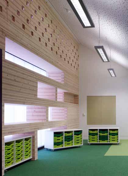
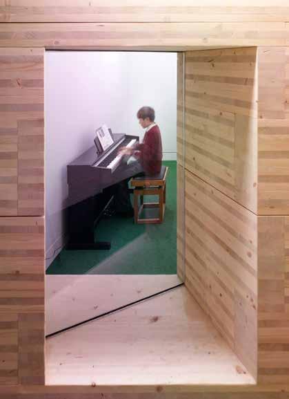
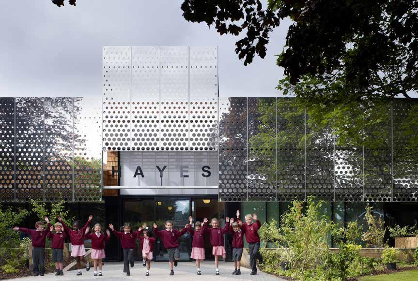
130
© Kilian O’Sullivan
HAYES PRIMARY SCHOOL
Croydon Council
LOCATION
Kenley, Surrey
20 ft (6 m) / 1 storey
CONSTRUCTION COST
£2.7 million
HEIGHT / STOREYS ARCHITECT
Hayhurst and Co.
STRUCTURAL ENGINEER
Providing 105 additional pupil spaces, and comprising 4 new classrooms, ICT lab, hall, administration facilities and external play and learning spaces, the expansion of Hayes Primary School brings renewed energy to a tired and out-dated building which had grown in a piecemeal and incoherent fashion.
The new building sits in a semi-rural location behind a cluster of mature trees. The glazed elevation allows classrooms to look out onto the new landscaped grounds, while a large mirrored façade provides shade from the solar glare and reflects the canopies of the mature trees giving the illusion of a reduced mass.
TIMBER ENGINEER
Eurban Crofton Design
TIMBER CONTRACTOR
Eurban
TIMBER MANUFACTURER
Schilliger Holz / Stora Enso
MAIN CONTRACTOR
The hybrid structure uses CLT for spine walls and pitched roofs with concrete block walls and glulam beams. Through timber exposed internally and externally the design reflects the woodland nature of the site.
TIMBER VOLUME
5,300 ft 3 (150 m 3)
TIMBER ASSEMBLY
3 weeks
OVERALL CONSTRUCTION
60 weeks
One of the key features of the school is a 250 foot long, 25 inch deep wall made of horizontally stacked CLT panels. This wall is a key navigation point in the school which identifies the circulation route and delineates the infant teaching space. The solid timber pieces are cut and stacked to form openings in the wall, through to the classrooms, and has recesses on alternating sides that form shelves for the school library, seats and reading alcoves as well as storage for classroom equipment and teaching materials.
STRUCTURE TYPE
Pure Timber Kier
EMBODIED CARBON WITHIN TIMBER*
-91 tons (-83 tonnes) CO 2 e
CLT FACT
The solid timber storage wall acts as a carbon sink
131
Section
2012 Education
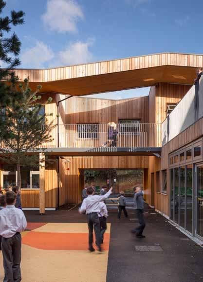
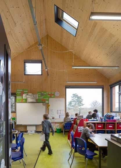

132
© Tim Crocker
Education AlphaPlus HILDEN GRANGE PREPATORY SCHOOL
LOCATION
Tonbridge, Kent
39 ft (12 m) / 3 storeys
CONSTRUCTION COST
£4.5 million
HEIGHT / STOREYS ARCHITECT
Hawkins\Brown
STRUCTURAL ENGINEER
Price & Myers
TIMBER ENGINEER
Engenuiti
TIMBER CONTRACTOR
B & K Structures
TIMBER MANUFACTURER
Binderholz
MAIN CONTRACTOR
BAM Construction
TIMBER VOLUME
19,200 ft 3 (543 m 3)
TIMBER ASSEMBLY
8 weeks
The brief was to reinvigorate a tired school that was lacking in facilities. Hawkins Brown’s design combines innovative and economical construction methods to design a new school on a steeply sloping site.
Terraced external play areas dominate the scheme, and are flanked on either side by two horizontally descending teaching blocks. These two wings are connected by a large assembly and dining hall, the roof of which functions as a further terrace, linking the upper levels. Sheltered, external walkways replace corridors to create a sense of community and engage the interior with the exterior. The new scheme restores views of the surrounding countryside, which had been obscured by the addition of temporary classrooms.
The new building’s form was inspired by that of the main school, the pitched roof of the west wing recalling the original Victorian schoolhouse.
With the exception of the new assembly/dining hall, the new facilities are constructed of CLT. CLT was chosen to accelerate the program as the school had to be built within one academic year. In addition, the material choice minimized the building’s carbon footprint. The structure is exposed internally, reducing the use of dry-lining and ceilings thereby creating calm spaces for learning. Exposed service runs encourage pupils at the school to understand the modern construction methods of the building.
58 weeks
STRUCTURE TYPE
OVERALL CONSTRUCTION Pure Timber
EMBODIED CARBON WITHIN TIMBER*
-333 tons (-302 tonnes) CO 2 e
CLT FACT
Enabled cost effective construction of school within one year
133
2012
Ground Floor Plan
Upper
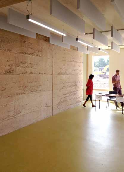
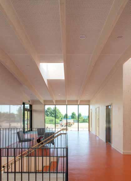
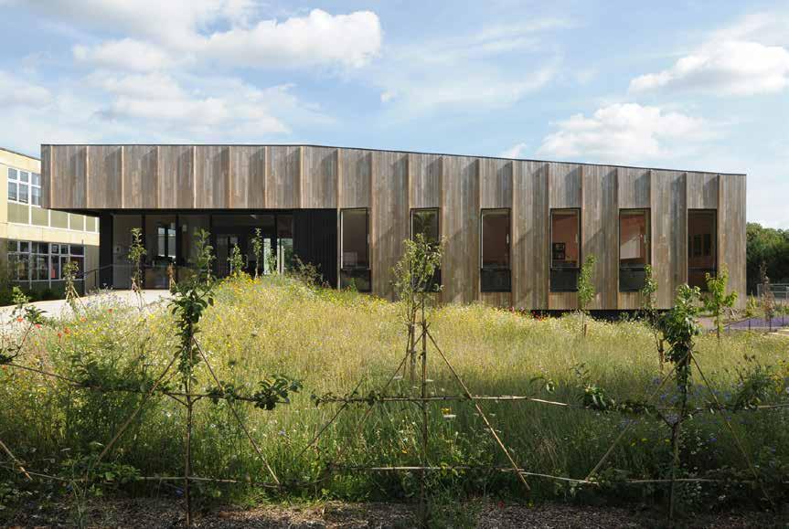
134
© Henrietta Williams
© Chris Pendrich © Chris Pendrich
LOCATION
Bath, Somerset 2013 Education
Bath & North East Somerset Council THE LEE CENTRE
The Lee Centre is the first major building within a broader masterplan for the Ralph Allen School campus. The two-storey Applied Learning Centre focuses on science, the foundation school’s specialist subject.
30 ft (9 m) / 2 storeys
CONSTRUCTION COST
£1.42 million
HEIGHT / STOREYS ARCHITECT
Feilden Fowles Architects
STRUCTURAL ENGINEER
Ramboll
TIMBER ENGINEER
Eurban
TIMBER CONTRACTOR
Eurban
TIMBER MANUFACTURER
Stora Enso
MAIN CONTRACTOR
H Mealing & Sons
TIMBER VOLUME
7,300 ft 3 (208 m 3)
TIMBER ASSEMBLY
4.5 weeks
OVERALL CONSTRUCTION
48 weeks
The structure is comprised of four classrooms, arranged in adjoining pairs around a double height breakout space for independent learning. It is designed in the round, with teaching spaces leading out onto the learning landscape. The series of open, flexible spaces are designed to encourage a university style of independent learning over the traditional school model. Located on greenfield land, adjacent to a world heritage site, the use of natural, low impact and environmentally responsible materials was essential. The project employs an earthy palette of materials, including polished concrete floors, rammed earth and timber designed to engage students and honestly express the structure.
Constructed in CLT, the building is partly embedded in the landscape, accessed by ramps leading up to the first floor gallery level. A hung larch façade marches across the elevations with a strong vertical rhythm, giving way to dark-stained timber at the lower level, used elsewhere to express deep cuts in the building envelope.
STRUCTURE TYPE
Pure CLT
EMBODIED CARBON WITHIN TIMBER*
-129 tons (-117.4 tonnes) CO 2 e
CLT FACT
Construction was able to continue in spite of the snow
135
Section


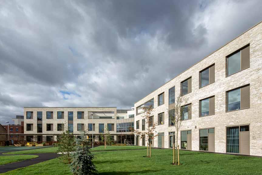
136
© Daniel Shearing
Education
ICKBURGH SCHOOL
Hackney Council
£14 million London Borough of Hackney
41 ft (12.5 m) / 3 storeys
CONSTRUCTION COST
ARCHITECT
Ickburgh School provides specialist accommodation for 150 pupils aged between 2-19 years on the Profound and Multiple Learning Difficulties spectrum. The brief demanded a number of bespoke amenities, such as four large lifts at key access points, high acoustic insulation and large corridors to allow for ease of movement of pupils in wheelchairs.
STRUCTURAL ENGINEER
TIMBER ENGINEER
TIMBER CONTRACTOR
The school is arranged in an L-Shape which minimizes overshadowing to the external spaces, and allows the majority of the classrooms to enjoy an outlook over the secluded garden. A visitor entrance on the corner of Kenworthy Road creates a strong civic presence while a triple-height, top-lit atrium space, with a café on the ground floor forms the social heart of the school.
Stora Enso Eurban Mouchel Avanti Architects
Classrooms and support rooms are organized into five clusters for different age groups, each of which enjoys a front door accessed from a central lightwell cultivating a feeling of intimacy.
TIMBER MANUFACTURER
MAIN CONTRACTOR
TIMBER VOLUME
The use of a CLT structure provided program savings and a highly sustainable, low carbon building. Exposed CLT makes a substantial contribution to the internal architectural expression within the classrooms and shared spaces, creating a calming environment for the students and teachers.
TIMBER ASSEMBLY
OVERALL CONSTRUCTION 10 weeks
HEIGHT / STOREYS Pure CLT McLaren Construction
52,500 ft 3 (1,488 m 3) 52 weeks
STRUCTURE TYPE
Kenworthy Rd
EMBODIED CARBON WITHIN TIMBER*
CLT FACT
Exposed CLT creates a calming environment for students Eurban -928 tons (-842 tonnes) CO 2 e
137
LOCATION
2013 First Floor Plan in Context
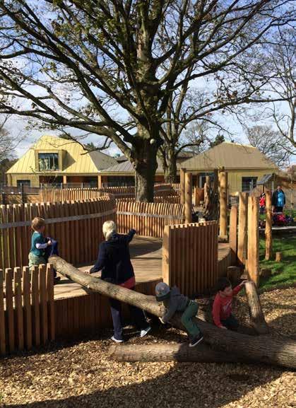

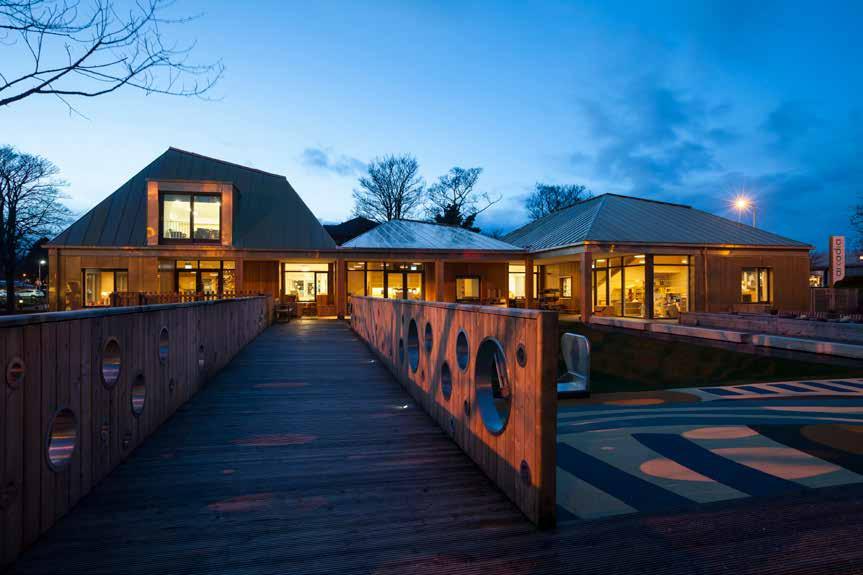
138
© Angus Brenmer
© Angus Brenmer © Malcolm Fraser
LOCATION
Edinburgh, Lothian
HEIGHT / STOREYS
30 ft (9 m) / 2 storeys
CONSTRUCTION COST
£2.5 million
ARCHITECT
Malcolm Fraser Architects
STRUCTURAL ENGINEER
Applied Engineering
Design (AED)
TIMBER ENGINEER
Applied Engineering
Design (AED) / Eurban
TIMBER CONTRACTOR
TIMBER MANUFACTURER
Stora Enso
MAIN CONTRACTOR
Balfour Beatty
TIMBER VOLUME
10,200 ft 3 (290 m 3)
TIMBER ASSEMBLY
OVERALL CONSTRUCTION
Education
ARCADIA NURSERY
University of Edinburgh
The Arcadia Nursery provides early-years education for up to 113 children of Edinburgh university staff, students and the general public, aged between six weeks to five years.
The building is designed around a ‘free-play’ concept that encourages age groups to mix in order to develop children’s confidence, independence and creativity. Three playrooms for different age groups are connected via a flexible central space containing shared, creative, ‘messy’ play spaces accessed through large sliding doors.
The three zones of the building are defined by their trapezoidal pyramid roofs, each one distinguished by its size and shape. The babies room is a cosy, domestic height single storey, while the rooms for the elder children are taller with raised mezzanine spaces to provide variety in spatial experience. Each roof is constructed of cross-laminated timber panels, supported on a continuous glulam ring beam to contain thrust from the roof form.
STRUCTURE TYPE
Pure Timber
EMBODIED CARBON WITHIN TIMBER*
-173 tons (-157 tonnes) CO 2 e
CLT FACT
Enabled complex roof forms without the need for columns
Eurban Sections 48 weeks 6 weeks
CLT was found to be the ideal material for such expressive roof forms enabling a column free space beneath for the arrangement of rooms and play decks at different levels. Left exposed throughout, it also provides a warm, tactile interior.
139
2014
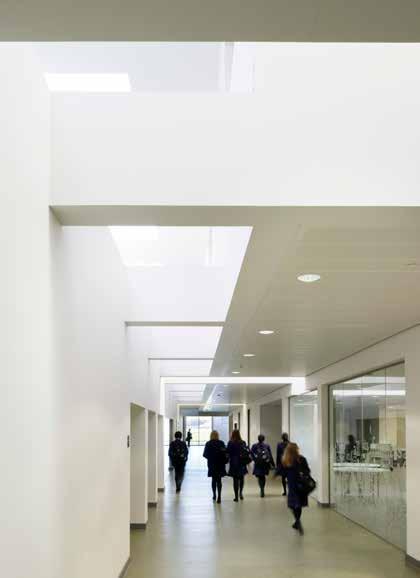


140
© Jim Stephenson
London Borough of Ealing
64 ft (19.5 m) / 4 storeys
CONSTRUCTION COST
£ 18 million
STRUCTURAL ENGINEER ARCHITECT
Feilden Clegg Bradley Studios
TIMBER ENGINEER
TIMBER CONTRACTOR
TIMBER MANUFACTURER
MAIN CONTRACTOR
TIMBER VOLUME
TIMBER ASSEMBLY
OVERALL CONSTRUCTION
STRUCTURE TYPE
EMBODIED CARBON WITHIN TIMBER*
CLT FACT
A 12 month construction program necessitated the use of
WILLIAM PERKIN CHURCH OF ENGLAND SCHOOL
Education Education Funding Agency
Driven by site constraints a simple yet elegant concept was conceived for this school. Required to have a footprint which was no greater than the redundant buildings that were demolished on the site and bounded on one side by an urban motorway, the new school is composed of two distinct parts. The rectangular ‘bar’ building, and the triangular ‘apex’ are connected by a street at ground floor and by an elegant running stair, which flows above it from ground to third floor.
Externally the building offers both a shield to the urban motorway and a welcoming presence to its community with a line of poplar trees, historically planted to shield the sports ground, and taken as a device to orientate the circulation route internally.
Inside the aim was to provide an open and airy space. The main four-storey triangular building is skirted by balconies looking onto a large library and a central performance studio.
The school was required to be open within 12 months of construction work starting which resulted in the choice of CLT for the superstructure. Used in conjunction with glulam beams to facilitate large-span spaces (sports hall and main hall) the interior is characterized by top lit spaces and exposed timber that brings warmth and lightness to the dramatic interior.
141
LOCATION
Timber
HEIGHT / STOREYS Pure
Kier
KLH UK
First Floor Plan
CLT
2014
83 weeks 15 weeks -2,318 tons (-2,103 tonnes) CO 2 e
132,400 ft 3 (3,750 m 3) KLH Massivholz Ramboll AECOM
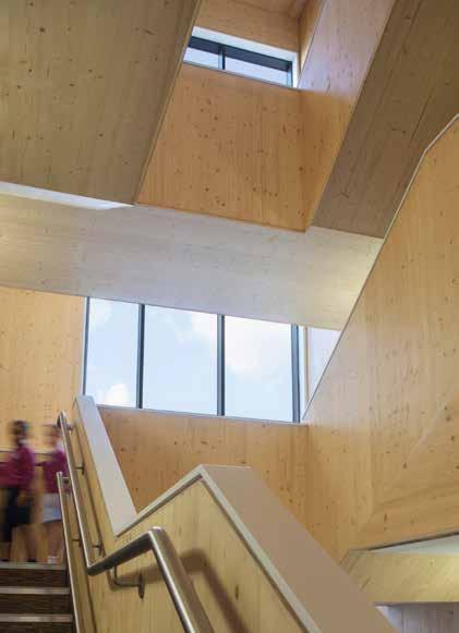
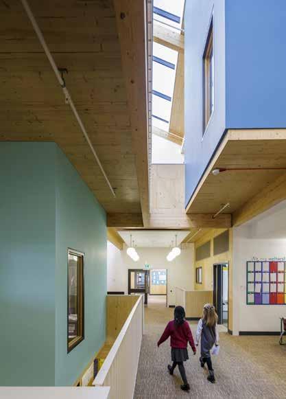
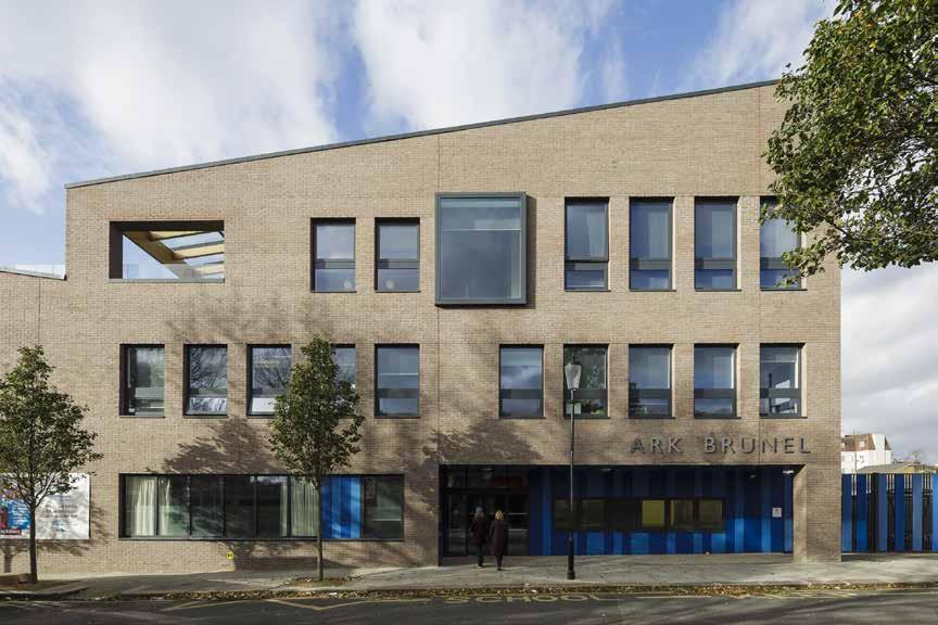
142
©Tim Crocker
©Richard Brine ©Tim Crocker
2014
Education
ARK BRUNEL PRIMARY ACADEMY
Kensington & Chelsea London Borough Council
Royal Borough of Kensington and Chelsea
HEIGHT / STOREYS
49 ft (15 m) / 3 storeys
Providing 420 primary school places, a 30 place kindergarten and a speech and language centre for 16 pupils, this new academy is part of a larger mixed use scheme on the site of the former Middle Row School.
£8 million
CONSTRUCTION COST ARCHITECT
Penoyre & Prasad
STRUCTURAL ENGINEER
Price & Myers
TIMBER ENGINEER
Price & Myers
TIMBER CONTRACTOR
B & K Structures
TIMBER MANUFACTURER
MAIN CONTRACTOR
The small footprint is maximized by flipping the conventional school building onto its side creating a three-storey form. Organized around staggered voids which create mini atria, the spatial organization provides inter-connectivity through the building’s core and a sense of progression through the school –children growing up while moving up the building.
Around these mini atria, stacked ‘learning clusters’ comprise two pairs of classrooms and learning spaces. Corridors were designed out, bringing all shared spaces into active use.
CLT is used as both structural and surface finish material to provide an economic design that reduced time and disruption on site and provides a warm and textured internal environment. The CLT forms the load bearing timber walls, floors, beams and roof and is combined with glulam beams to support the large roof span of the double height space. Stability is achieved by the floor panels acting as horizontal diaphragms to transfer wind loads to the walls, while the walls act as shear walls transferring these loads back to the foundations.
STRUCTURE TYPE
EMBODIED CARBON WITHIN TIMBER*
CLT FACT
143
LOCATION
Pure
BAM Construction
m 3)
CO 2 e
TIMBER VOLUME TIMBER ASSEMBLY OVERALL CONSTRUCTION
Timber
35,500 ft 3 (1.006
-617 tons (-560 tonnes)
Designed to allow the future removal of certain panels for flexibility 60 weeks 13 weeks Binderholz
Section
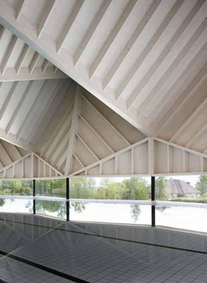
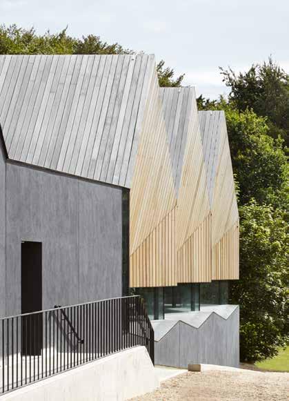
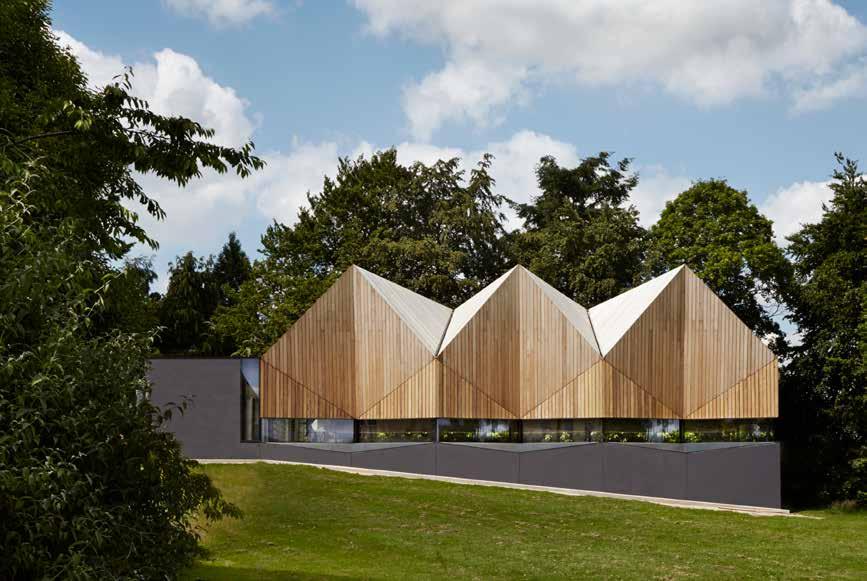
144
© Jack Hobhouse
LOCATION
Beaconsfield, Buckinghamshire
HEIGHT / STOREYS
20 ft (6 m) / 2.5 storeys
CONSTRUCTION COST
£1.8 million
ARCHITECT
Duggan Morris Architects
STRUCTURAL ENGINEER
Elliot Wood
TIMBER ENGINEER
Westmuckett Hawkes
TIMBER CONTRACTOR
Cowley Timber & Partners
TIMBER MANUFACTURER
Cowley Timber & Partners / Dold / Lilleheden
MAIN CONTRACTOR
Feltham Construction
TIMBER VOLUME
2,100 ft 3 (60 m 3)
TIMBER ASSEMBLY
5 weeks
OVERALL CONSTRUCTION
65 weeks
Sports & Leisure (Education)
School
This extension to a sports department within a special needs school provides a four lane pool, changing facilities, gym and fitness suites within a raised timber structure. Drawing on the geometry of the roof pitches of the rest of the school, it is designed as a timber hat articulated by three folded roof segments that open to the rear, inverting the pitch.
This expressive sculptural form, which is evocative of ripples within the pool, acts as an acoustic baffle preventing high reverberation of sound, one of the primary considerations of the brief.
The prefabricated roof structure was designed around the maximum size that could be delivered to site on a truck. Each of the 12 triangulated truss modules was manufactured off-site and delivered on a just-in-time basis complete with service routes, and pre-finished with waterproofing and coatings. As such no follow on trades were required to work over the swimming pool and the roof structure assembly was completed without the erection of internal or external scaffolding.
STRUCTURE TYPE
Hybrid
EMBODIED CARBON WITHIN TIMBER*
-32 tons (-29 tonnes) CO 2 e
CLT FACT
Sculptural CLT ceiling doubles as an acoustic baffle
The repetition of the structure exploited the efficiencies possible through off-site fabrication. Isonometric
145
Eye View
Worms
2014
Alfriston
ALFRISTON SCHOOL SWIMMING POOL
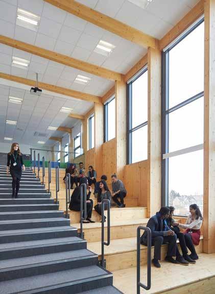
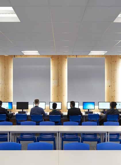
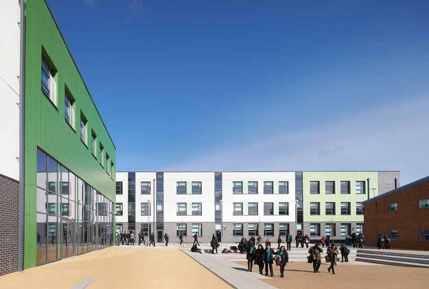
146
© Hufton
+
Crow
Education Redbridge Council MAYFIELD SCHOOL
London Borough of Barking and Dagenham
HEIGHT / STOREYS
39 ft (12 m) / 3 storeys
CONSTRUCTION COST ARCHITECT
£18.2 million
David Miller Architects
STRUCTURAL ENGINEER
Ramboll
TIMBER ENGINEER
Ramboll
TIMBER CONTRACTOR
KLH UK
TIMBER MANUFACTURER
KLH Massivholz
MAIN CONTRACTOR
TIMBER VOLUME
110,500 ft 3 (3,128 m 3)
With a 17-month program from design to completion this 91,000ft 2 school extension was only viable in CLT. Providing capacity to accommodate an additional 800 pupils and 80 staff, this new building delivers educational needs alongside their ambition to create a ‘culture of aspiration’. Uplifting and flexible teaching spaces, a new social heart around a Hellerup stair and extensive sports facilities bring new opportunities for students and the local community.
The aesthetic aim was to develop a new visual style for the school, which could be drawn upon for the redevelopment of other blocks within the larger site. A mix of robust brick with 3 shades of Trespa cladding and render was chosen, the vast sports hall differentiated by a staggered pattern.
A set of “rules” was applied to the early design in order to maximize the efficiency of the CLT by optimizing spans and widths. Glulam was incorporated where wider spans were needed. Where possible the timber was expressed as part of the design concept bringing lightness and warmth to the interiors. The off-site manufacturing allowed the frame of the building to be removed from the critical path, while the low weight eliminated the need for piled foundations. This ensured the program could be met and disruption to the existing school was minimized. Fit-out was able to commence on the lower floors while the upper floors were still being erected.
12 weeks
TIMBER ASSEMBLY OVERALL CONSTRUCTION
74 weeks
STRUCTURE TYPE LOCATION
EMBODIED CARBON WITHIN TIMBER*
CLT FACT
The use of BIM eased the translation of the design into CLT panels
147
Timber Bouygues UK
Pure
-1,961 tons (-1,778.6 tonnes) CO 2 e
2014
Sectional Axonometric of CLT

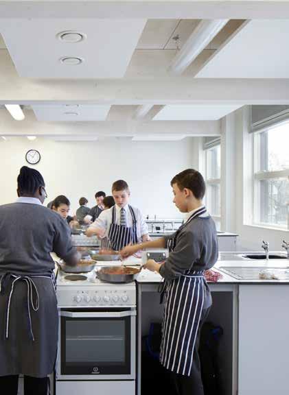
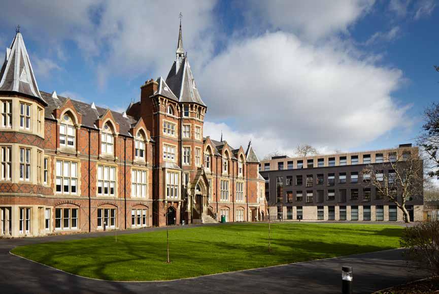
148
© Jack Hobhouse
LOCATION
London Borough of Hackney
HEIGHT / STOREYS
49 ft (15 m) / 4 storeys
CONSTRUCTION COST
£12 million
ARCHITECT
Jestico + Whiles
STRUCTURAL ENGINEER
Mouchel
TIMBER ENGINEER
Eurban
TIMBER CONTRACTOR
Eurban
TIMBER MANUFACTURER
Stora Enso
MAIN CONTRACTOR
HG Construction
TIMBER VOLUME
38,700 ft 3 (1,097 m 3)
TIMBER ASSEMBLY
Education
MOSSBOURNE VICTORIA PARK ACADEMY
Mossbourne Victoria Park Academy
This new school reworks the existing 19th century French hospital building adding a part single (double-height) and part four-storey block to create a high school for 800 students.
The new building houses all the specialist teaching spaces, including art, science, D&T and music, while the historic building accommodates general teaching and library space, and a drama space in the former chapel.
Developed in the shadow of the existing structure, the new four-storey building encroaches as little as possible either physically, on the open space around the listed building, or visually on views towards the building.
Timber was utilized throughout the new building. All floors, walls and roof slabs are 100% CLT in addition to the large span sports hall and staircases. Glulam beams were utilized on the corridor to enable maximum flexibility of internal layout. Internally the CLT is left exposed with the wood’s natural grain being subtly visible beneath the surface spread of flame white wash.
Timber is also seen in the windows and integrated acoustic ventilation louvres. An extensive green roof is planted with grasses and wild flowers, adding to the building’s sustainability credentials. The main roof of the building has an array of solar panels concealed by a timber veil of Siberian larch.
52 weeks 4 weeks
OVERALL CONSTRUCTION
STRUCTURE TYPE
Pure Timber
EMBODIED CARBON WITHIN TIMBER*
-671 tons (-609 tonnes) CO 2 e
CLT FACT
8 week program saving enabled delivery in time for term start
First Floor Plan
149
in Context
2014
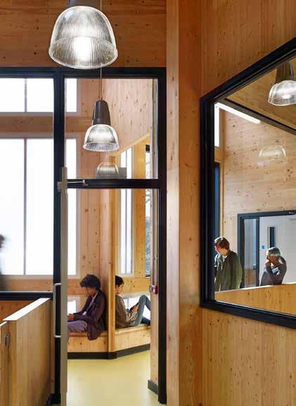
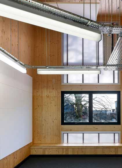
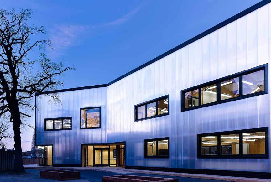
150
© Killian O’Sullivan
2014
London Borough of Wandsworth
33 ft (10 m) / 2 storeys
CONSTRUCTION COST
£ 976,000
ARCHITECT
Urban Projects Bureau
STRUCTURAL ENGINEER
Furness Partnership G-Frame
TIMBER ENGINEER
TIMBER CONTRACTOR
TIMBER MANUFACTURER
Stora Enso
MAIN CONTRACTOR
TIMBER VOLUME
8,200 ft 3 (232 m 3)
TIMBER ASSEMBLY
OVERALL CONSTRUCTION
52 weeks
STRUCTURE TYPE
EMBODIED CARBON WITHIN TIMBER*
CLT FACT
Exposing the CLT reduced the cost of expensive linings
GRAVENEY SIXTH FORM
Education Graveney School
With a budget of £1 million and a 12-month program to create a new senior school block, the architect reviewed the various prefabricated, modular and bespoke construction options for delivery within these constraints. CLT was selected for its rapid on-site construction, sustainability, feel and appearance. Through achieving maximum architectural output using minimal means, UPB have, through their design, set a realizable template for new school buildings in the current climate of short-termism and austerity.
The 8,600ft 2 building minimizes unnecessary floor area and maximizes daylight penetration and airflow. All the ground floor classrooms open directly onto sheltered external porches rather than corridors, and the first floor classrooms are all accessed directly via the two staircases. A doubleskin polycarbonate front façade opens to frame views across the surrounding campus and also regulates solar gain.
Designed to be naturally ventilated all classrooms, staircases and doubleheight spaces are double or triple aspect, with cross ventilation and stack ventilation through high-level rooflights. The spaces are naturally lit throughout the day, reducing the need for electric lighting. Exposed CLT omits the need for internal linings, reducing material use and cost. The CLT frame, with translucent panels, cladding and openings, shapes the building and gives it character.
151
LOCATION
e
HEIGHT / STOREYS Pure Timber Ashe Construction -144 tons (-131 tonnes) CO 2
G-Frame 6 weeks
Floor Plan
First
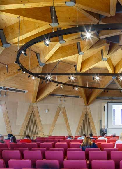
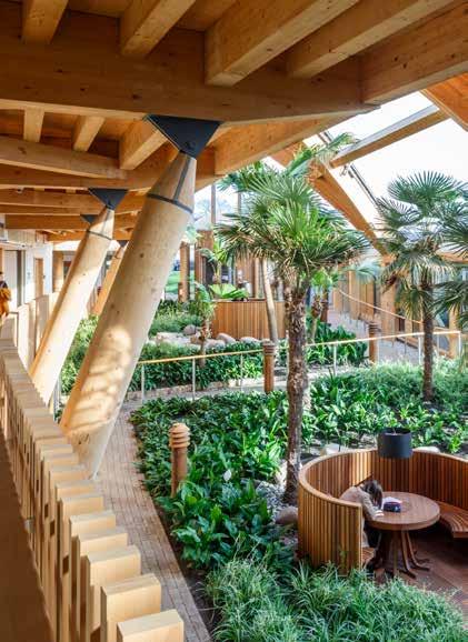

152
© Gareth Gardner
Colchester, Essex 2015
Education
ESSEX UNIVERSITY BUSINESS SCHOOL
University of Essex
LOCATION
46 ft (14 m) / 3 storeys
CONSTRUCTION COST
£14.7million
HEIGHT / STOREYS ARCHITECT
BDP
STRUCTURAL ENGINEER
BDP
TIMBER ENGINEER
Engenuiti
TIMBER CONTRACTOR
B & K Structures
TIMBER MANUFACTURER
Binderholz
MAIN CONTRACTOR
Morgan Sindall
TIMBER VOLUME
45,200 ft 3 (1,279 m 3)
TIMBER ASSEMBLY
28 weeks
Located in parkland on a hillside overlooking an estuary, this new business school forms an important link between the existing 1960s campus and the new knowledge gateway research park.
The three-storey building provides teaching space, a 250-seat lecture theatre and a winter garden that acts as an entrance and meeting space, with a café at one end and social spaces for students and staff at the other.
A zero carbon approach was at the forefront of the design resulting in a building which is visibly sustainable at every level: from its orientation on site; choice of structure and materials; to landscaping and passive engineering strategies. Shaped as a ‘sundial’ crescent the building is orientated with its centre point to the midday sun. The winter garden forms the inner ring to the crescent, running down the slope on the south side creating a major environmental buffer space that tempers the building, like a conservatory to a grand house.
The sustainably sourced curved timber frame and cladding were key aspects of the specification and thoughtfully integrate the building into a site surrounded by mature parkland. The hybrid frame incorporating substantial glulam beams alongside CLT allowed for the impressive volumes of the lecture theatres.
69 weeks
STRUCTURE TYPE
OVERALL CONSTRUCTION Hybrid
EMBODIED CARBON WITHIN TIMBER*
-769 tons (-698 tonnes) CO 2 e
CLT FACT
The first zero-carbon business school in the UK
153
Section
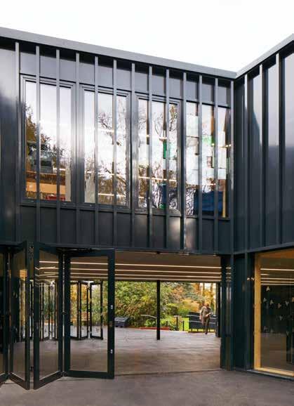
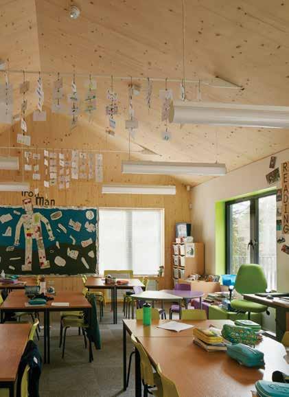
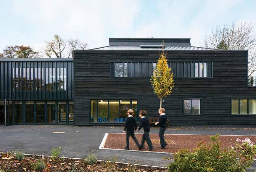
154
© Dennis Gilbert
LOCATION
Beaconsfield, Buckinghamshire
HEIGHT / STOREYS
31 ft (9.3 m) / 2 storeys
CONSTRUCTION COST
£4.6 million
ARCHITECT
DSDHA
STRUCTURAL ENGINEER
engineersHRW (formerly Jane Wernick Associates)
TIMBER ENGINEER
KLH UK
TIMBER CONTRACTOR
KLH UK
TIMBER MANUFACTURER
KLH Massivholz
MAIN CONTRACTOR
DAVENIES BOYS PREPATORY SCHOOL
Education Davenies Prepatory School
Davenies School is a collection of buildings set around historic formal gardens. This phase of the school’s evolution consists of a new library, hall and 10 classrooms.
The various elements echo the school’s agricultural past. The “link” provides a connection with the school’s listed structures: the reception; a smaller scale environment for younger children; and the main wing, set around a verdant dell for learning and playing. These components are organized around a ground-tempered space that connects the historic garden to the new outdoor spaces.
Black ‘wavey’ edged timber clads the structure providing a striking contrast to the surrounding greenery. Its dark color reduces the perceived scale of the new building and harmonizes it with the historic setting.
CLT is used as the primary structure, forming the floor slabs, walls and roof structure. Left exposed internally the CLT contributes to the controlled material and color palette and provides the pupils with the opportunity to see how the building has been made.
A series of passive design measures, along with the CLT structure allowed this school to exceed the energy performance requirements of the building regulations.
TIMBER VOLUME
13,100 ft 3 (370 m 3)
TIMBER ASSEMBLY
OVERALL CONSTRUCTION
65 weeks
Hybrid Beard Construction
STRUCTURE TYPE
EMBODIED CARBON WITHIN TIMBER*
7 weeks -230 tons (-208 tonnes) CO 2 e
CLT FACT
10% lower CO2 emissions than the notional building
155
2015
First Floor Plan in Context

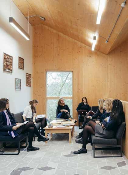
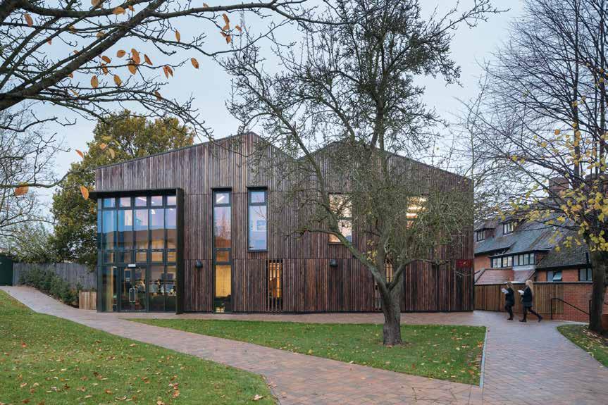
156
© Tim Crocker
Bishop’s Stortford, Hertfordshire
Education
WYNCH COTTAGE
Bishop’s Stortford College
The first phase in the site wide masterplan, this project relocated and enhanced one of the college’s day houses unlocking a site designated for further development.
26 ft (8 m) / 2 storeys
CONSTRUCTION COST HEIGHT / STOREYS
£1 million
ARCHITECT
Hawkins\Brown
STRUCTURAL ENGINEER
Smith and Wallwork
TIMBER ENGINEER
Smith and Wallwork
TIMBER CONTRACTOR
The existing day house was beyond its working life, and in need of an upgrade. The project re-purposed and enhanced the existing Arts & Crafts building with a new extension. This phase of the masterplan also established a visual language for the development with exposed CLT, charred timber cladding and folded plate and pitched roofs delivering flexible, light, open spaces whilst offering variations on the traditional character of the conservation area.
The proximity to existing mature trees and buildings required careful consideration of the footprints, heights, and buildability. The CLT extension provides structural support to the existing cottage, which facilitates the opening up of the rear façade to connect into the new double height spaces.
TIMBER MANUFACTURER
KLH Massivholz KLH UK
MAIN CONTRACTOR
TIMBER VOLUME
TIMBER ASSEMBLY
OVERALL CONSTRUCTION
The extension utilizes a CLT folded-plate roof to create large spans to the social spaces. CLT and services are exposed as features, minimizing costs, and providing a robust, contemporary finish to the new day house.
STRUCTURE TYPE
EMBODIED CARBON WITHIN TIMBER*
CLT FACT
Success here has ensured CLT’s use for the masterplan phases
157
LOCATION
Pure CLT Hutton
tons (-81 tonnes) CO 2 e
Construction -89
2
2,3&4 41 weeks
weeks 5,000 ft 3 (143 m 3)
2015 First Floor Plan
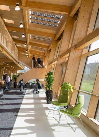
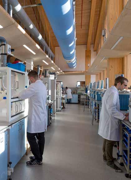
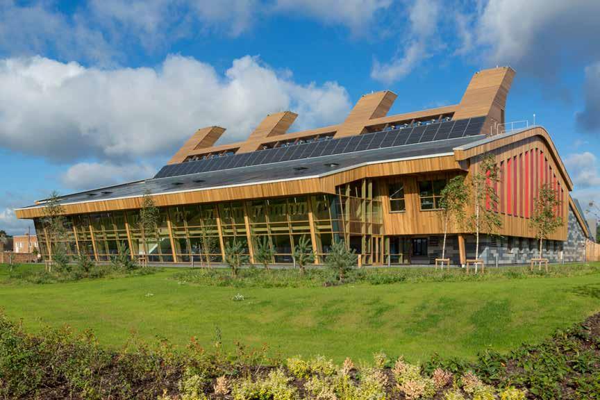
158
© Martine Hamilton-Knight
2016 Education
GSK CENTRE FOR SUSTAINABLE CHEMISTRY
GlaxoSmithKline / University of Nottingham
Nottingham, Nottinghamshire
72 ft (21.9 m) / 2 storeys
£15.8 million
Fairhursts Design Group
ENGINEER
The objective of this project was to create a laboratory that would make no overall contribution to greenhouse gases throughout its entire lifecycle: from off-site procurement, site construction, and occupation to eventual demolition.
The use of a timber frame, alongside passive ridge ventilation and photovoltaics for renewable energy production, was essential in assuring this target would be met.
Constructed with a glulam frame, CLT panels form the floors, roof deck, exterior walls, and a number of internal divisions. Exposed timber finishes internally ensured limited linings and a resulting carbon benefit.
The stability of the structure comes from the CLT with steel cross-bracing at roof level transferring the loads into the vibro-stone foundations – a solution which limits the use of concrete and is possible due to the lighter weight of the timber frame.
Built at the lowest possible carbon cost, the building’s renewable energy supply offsets the carbon associated with its energy efficient equipment, services and construction and sends surplus energy to the grid, while the CLT acts as a carbon sink. It has been calculated that all carbon associated with both the construction and operation of the building will be paid back within 25 years.
159 LOCATION
WITHIN TIMBER*
STRUCTURE TYPE HEIGHT / STOREYS
STRUCTURAL
TIMBER
TIMBER
EMBODIED CARBON
CLT FACT
CONSTRUCTION COST ARCHITECT
ENGINEER
MANUFACTURER
TIMBER VOLUME TIMBER ASSEMBLY OVERALL CONSTRUCTION Pure Timber Morgan Sindall -1,227 tons (-1,113 tonnes) CO 2 e 71,500 ft 3 (2,025 m 3) 18 weeks Completely carbon neutral laboratory B & K Structures TIMBER CONTRACTOR Section 78 weeks Binderholz / Derix AECOM / Engenuiti AECOM
MAIN CONTRACTOR
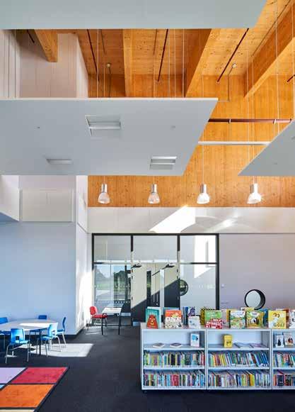
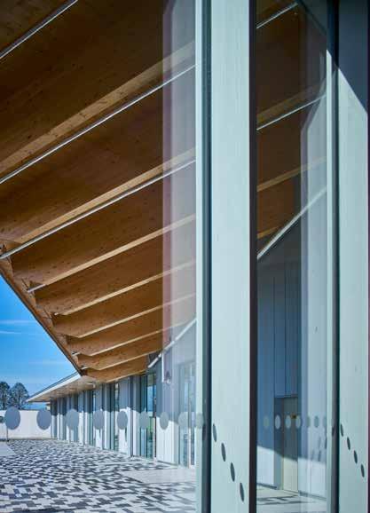
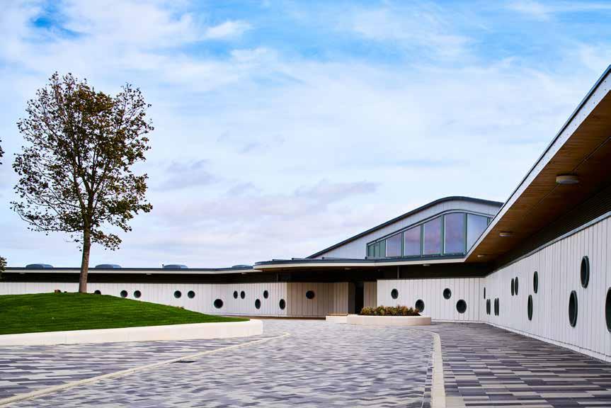
160
© Tim Soar
2016 Education
ALCONBURY WEALD PRIMARY SCHOOL
LOCATION
Huntingdon, Cambridgeshire
HEIGHT / STOREYS
13 - 33 ft (4 - 10 m) / 1-2 storeys
CONSTRUCTION COST
£7.8 million
ARCHITECT
Allford Hall Monaghan Morris
STRUCTURAL ENGINEER
Peter Dann Consulting Engineers
TIMBER ENGINEER
Ramboll
TIMBER CONTRACTOR
The three-winged plan of this new primary school echoes the site’s rich avionic history and provides classrooms that have direct access to generous external areas. A double-height space in the centre of the plan is a modern re-interpretation of the reinforced concrete hangars housing shared facilities that can be used by the local community when the school is closed.
As the first civic building on a larger masterplan the school sets the intent for design quality around which the community will be developed.
Designed from the outset to have a CLT superstructure the frame has been thoughtfully and pragmatically exposed throughout the development, providing a strong aesthetic language whilst also reducing the need for applied finishes, thereby reducing costs. Extensive acoustic studies were completed to ensure the areas with higher acoustic performance requirements were met, occasionally resulting in the depth of certain CLT walls being increased beyond their structural necessity.
TIMBER MANUFACTURER
KLH Massivholz
MAIN CONTRACTOR
Using CLT reduced on site works by 6-8 weeks which enabled the challenging construction program to be realized. The school opened only two years after design work had commenced.
TIMBER VOLUME
52,800 ft 3 (1,495 m 3)
TIMBER ASSEMBLY
10.5 weeks
OVERALL CONSTRUCTION
54 weeks
STRUCTURE TYPE
Morgan Sindall Pure Timber
EMBODIED CARBON WITHIN TIMBER*
KLH UK -924 tons (-838 tonnes) CO 2 e
CLT FACT
Cost reductions through leaving CLT exposed
161
Ground Floor Plan
Morgan Sindall for Cambridgeshire County Council / Urban & Civic
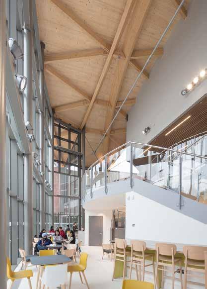


162
© Quintin Lake
Warwick, Warwickshire 2016
Education
OCULUS TEACHING BUILDING
The University of Warwick
LOCATION
HEIGHT / STOREYS
46 ft (14 m) / 3 storeys
CONSTRUCTION COST
£14.2 million
ARCHITECT
Berman Guesdes Stretton
STRUCTURAL ENGINEER
Copeland Wedge Associates (CWA)
TIMBER ENGINEER
B & K Structures
TIMBER CONTRACTOR
B & K Structures
TIMBER MANUFACTURER
Binderholz
MAIN CONTRACTOR
Willmott Dixon
TIMBER VOLUME
44,100 ft 3 (1,250 m 3)
TIMBER ASSEMBLY
10 weeks
OVERALL CONSTRUCTION
73 weeks
Located at the social centre of campus, the Oculus provides the University of Warwick with its first building dedicated purely to teaching and available to all academic departments. Just fewer than 1,400 new teaching seats are delivered within two raked lecture theatres and a range of flat-floored teaching rooms which accommodate groups ranging in size from 30 to 100.
The teaching spaces are located in two wings that support a dramatic arched timber roof, beneath which are the lecture theatres. This impressive glulam timber roof, and the curved three-storey glass façade beneath it, is the statement feature of the building – making it instantly recognisable, boosting the natural aesthetic, and improving sustainability by reducing embodied carbon.
The building responds to its central location, being legible and accessible from all directions, with ground floor teaching spaces opening out onto terraces. Generous circulation spaces flow around the lecture theatres within and create enclaves of space for social learning whilst the inclusion of a café further promotes the use of the building by students beyond formal teaching sessions. The building sets the architectural direction of the wider university campus masterplan using a warm palette of natural materials, expansive and generous geometry, and a high degree of transparency and openness.
STRUCTURE TYPE
Hybrid
EMBODIED CARBON WITHIN TIMBER*
CLT FACT
Timber roof as a statement regarding sustainability
163
-775 tons (-703 tonnes) CO 2 e
Diagram of Roof Structure
Exploded
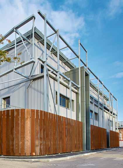
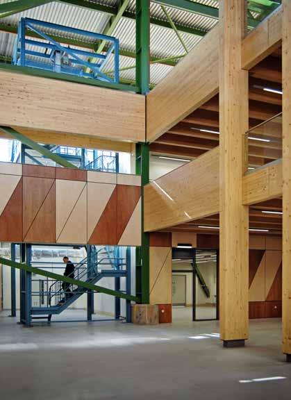
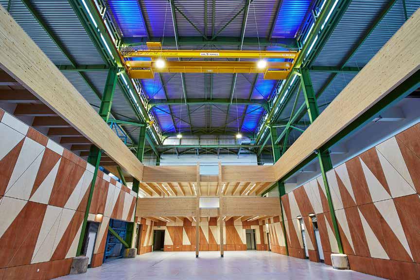
164
© Martin Cleveland
© Paul Younger © Martin Cleveland
Berkeley, Gloucestershire 2016
Education
SGS BERKELEY GREEN
South Gloucestershire and Stroud College
LOCATION
58 ft (17.7 m) / 3 storeys
CONSTRUCTION COST
£3.2 million
HEIGHT / STOREYS ARCHITECT
Hewitt Studios
STRUCTURAL ENGINEER
O’Brien & Price
TIMBER ENGINEER
O’Brien & Price
TIMBER CONTRACTOR
Hess Timber
TIMBER MANUFACTURER
Hess Timber / Pollmeier Massivholz
MAIN CONTRACTOR
The project is the first phase of the conversion and refurbishment of a former nuclear research and engineering centre to provide South Gloucestershire and Stroud College with a renewable energy and engineering skills hub. The building is designed to become an exemplar of regenerative investment and an educational tool in its own right with elements of the building fabric used to deliver specific areas of the curriculum (e.g. solar pv and timber construction).
Steel would have been the obvious choice for the alterations, but instead an innovative hybrid structure uses CLT floor slabs, supported on a network of LVL joists to keep floor depths to a minimum and co-ordinate with the existing building. The LVL used was made from Beech hardwood, the high strength (70N/mm2 vs. 48 N/mm2) of which allowed for a structure with significantly smaller dimensions compared to a laminated softwood solution. Limited construction space, due to the fact the prefabricated assembly had to take place within an existing building, necessitated the use of smaller sections and, where this was not possible, advanced crane and handling techniques.
The delivery of a reinvigorated, dynamic and sustainable facility re-using an existing building sets a low-carbon precedent for future developments.
TIMBER VOLUME
7,400 ft 3 (210 m 3)
TIMBER ASSEMBLY
52 weeks 3 weeks
OVERALL CONSTRUCTION
STRUCTURE TYPE
Pure Timber Kier
EMBODIED CARBON WITHIN TIMBER*
-135 tons (-122 tonnes) CO 2 e
CLT FACT
First use of hardwood LVL in the UK
165
Section

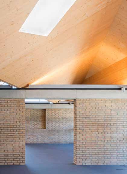
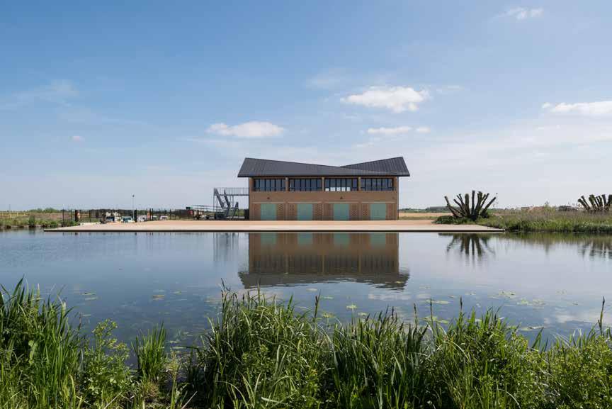
166
© Koen Van Damme
LOCATION
Ely, Cambridgeshire
HEIGHT / STOREYS
37 ft (11.4 m) / 2 storeys
CONSTRUCTION COST
£3 million
ARCHITECT
Jeremy Bailey Architects / Baynes and Mitchell
STRUCTURAL ENGINEER
Smith and Wallwork
TIMBER ENGINEER
Smith and Wallwork
TIMBER CONTRACTOR
KLH UK
TIMBER MANUFACTURER
KLH Massivholz
MAIN CONTRACTOR
Morgan Sindall
TIMBER VOLUME
6,900 ft 3 (194 m 3)
TIMBER ASSEMBLY
3 weeks
OVERALL CONSTRUCTION
65 weeks
Sports & Leisure (Education)
ELY BOATHOUSE
Cambridge University Boathouse
Built on a greenfield riverside site on a floodplain the design for the boathouse needed to be ecologically sensitive whilst also taking into consideration flood risk. The objective of the design was to create a building which would become an organic part of the riverbank, rooted in its setting.
The striking roof is formed of a folded CLT plate sitting on steel valley beams that span between concrete and reinforced brickwork cross walls. The twisted geometry of the folded roof creates an abstract silhouette, its shape mirroring the birds that fly over the adjacent waterways. The complex geometry of the roof required careful 3D modelling and the accurate CNC cutting possible with CLT, making for fast and easy assembly on site.
The timber, a natural material with low embodied carbon, ensures complicity between the building and the ecologically sensitive location. A new reed bed and lagoon created at the opposite end of the site provides an improved local habitat for wildlife.
STRUCTURE TYPE
Hybrid
EMBODIED CARBON WITHIN TIMBER*
-122 tons (-111 tonnes) CO 2 e
CLT FACT
Prefabrication enabled the complicated roof form
167
Section
2017
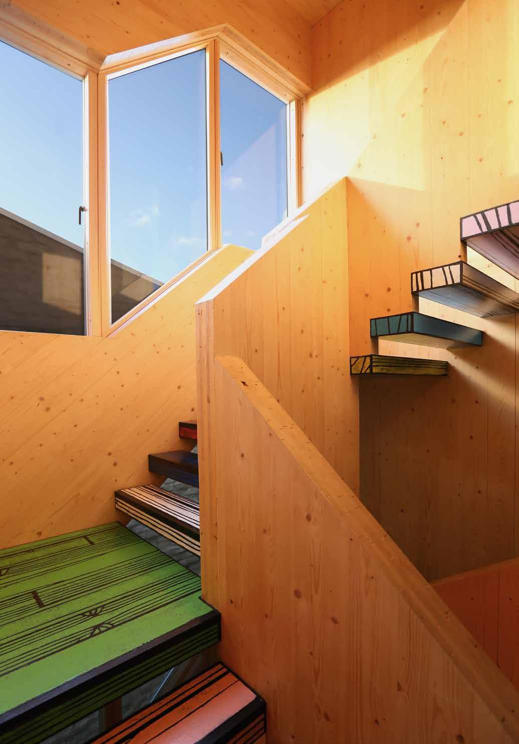
CLT as a product was initially developed to be aimed at the residential sector. Since then it has been consistently popular in these projects. The maximum span that can be achieved with CLT panels of average thickness is similar to the proportions of typical residential spaces. Due to this relationship, pure CLT structures, using little or no glulam/steel, are usually possible.
Residential projects constructed in CLT largely fall within one of two main categories. The first being individual one-off dwellings, typically where the client is building their own house. The use of CLT here is often driven by aesthetics, desire for exposed timber finishes and building sustainability. Time saving is usually less significant to clients of this type of scheme, whose primary focus tends to be on the creation of a high quality and beautiful home. For small low rise projects, where structural demands are less, CLT can provide a great deal of freedom in design which can lead to some interesting and impressive volumes. The natural robust walls are tactile, with an inherent ease of fixing to the structure. The lower requirements for fire and acoustics within individual dwellings mean exposing the timber is usually an easier process.
The second category is high-density, mid-to-high rise housing blocks. Here the key drivers for using CLT tend to be the ease and speed of construction. In such schemes the CLT is rarely exposed. This is primarily due to the fact that for these schemes the CLT itself is typically not capable of meeting the stringent requirements for fire and acoustics unless lined to at least one face. In addition to this, particularly for earlier schemes, issues with obtaining insurance and fears over the saleability of flats led to a client desire to conceal the structure's nature.
The potential to use CLT to create vast honeycomb structures delivering the many cellular volumes of a high-density housing scheme means that the program benefits offered by CLT can be truly optimized.
169
Image: Woodblock House, dRMM © Alex de Rijke
RESIDENTIAL
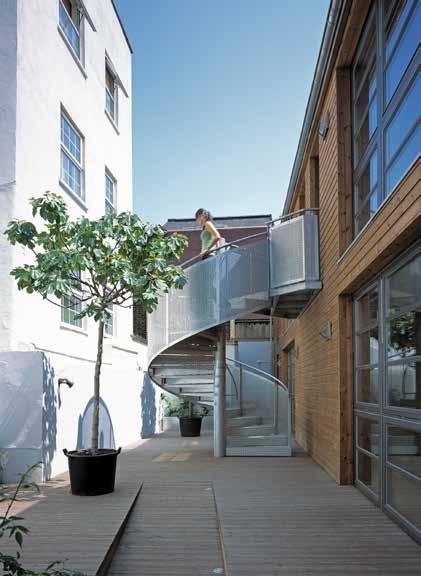

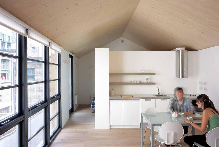
170
© Edmund Sumner
Residential Pringle & Richards LLP CARLISLE LANE
3 Carlisle Lane is a two-storey new-build residential scheme comprising four one-bedroom apartments on a tight urban site. Poor ground conditions combined with the site’s close proximity to a railway viaduct necessitated a lightweight structure with good acoustic properties. The solution was to construct the entire building envelope from prefabricated lightweight solid timber panels.
The site extends 65 foot back from Carlisle Lane but has a street frontage of just 23 foot. The concept was to split the site in two, with a long thin strip of built accommodation occupying the southern side and a private courtyard occupying the northern side. This approach was partly driven by the fact that three of the site boundaries are party walls and new window frontage could be created only within the site itself.
The new timber structure was built within the existing masonry perimeter walls which provide additional fire resistance, thermal mass and acoustic protection from the adjacent railway viaduct.
The lightweight nature of the CLT structure meant that the slab to the warehouse could also be retained with a new concrete raft cast over the top to spread the load. This obviated the need for more substantial foundations and piling on the poor quality ground, reducing costs.
171 LOCATION EMBODIED CARBON WITHIN TIMBER* CLT FACT STRUCTURE TYPE HEIGHT / STOREYS CONSTRUCTION COST ARCHITECT STRUCTURAL ENGINEER TIMBER ENGINEER TIMBER CONTRACTOR TIMBER MANUFACTURER
TIMBER VOLUME TIMBER ASSEMBLY OVERALL CONSTRUCTION Pure CLT DF Keane / Züblin Timber Lightweight CLT facilitated building on poor ground conditions Eurban -28 tons (-26 tonnes) CO 2 e 36 weeks 2 weeks 1,700 ft 3 (74 m 3) Züblin Timber (formerly Finnforest Merk) Eurban Alan Baxter Ltd. £350,000 Pringle Richards Sharratt 20 ft (6 m) / 2 storeys 2005 London Borough of Lambeth First Floor Plan
MAIN CONTRACTOR

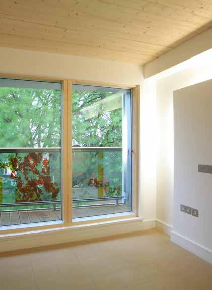
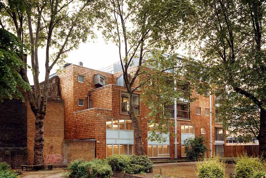
172
© Anthony Coleman
2006
Residential FAIRMULE HOUSE LINT Group
LOCATION
London Borough of Hackney
HEIGHT / STOREYS
45 ft (13.8 m) / 5 storeys
CONSTRUCTION COST
£1.6 million
ARCHITECT
Quay 2 c Architects
STRUCTURAL ENGINEER
Anders Associates
TIMBER ENGINEER
Eurban
TIMBER CONTRACTOR
Eurban
TIMBER MANUFACTURER
Züblin Timber (formerly Finnforest Merk)
MAIN CONTRACTOR
L I Construction
TIMBER VOLUME
15,000 ft 3 (425 m 3)
TIMBER ASSEMBLY
Thomas Fairchild, the first man to genetically modify plants to manufacture his famous “Fairchild Mule” hybrid, is buried in the pocket park to the rear of the site. The scheme was conceived with this in mind, and the desire to create a hybrid building ‘made from nature’ drove the concept. Originally designed for concrete and steel, a review of the scheme resulted in 11 dual aspect, cross-ventilated apartments, all but one of which have a private balcony or terrace. Apartments are accessed from two naturally lit common staircases which encourage horizontal circulation to take place in the street rather than the dark corridors of the original design. The ground and first floor provide seven commercial units of varying sizes to encourage a greater diversity of uses to compliment the flats above.
One of the first CLT buildings within the UK the timber sits on a concrete slab with a small steel portal to the ground floor of the 5 storey part of the building. Timber soffits are exposed throughout the apartments, a key requirement of the design.
The façades of the building are inspired by the Fairchild Mule including bespoke public art by Quay 2c’s Julia Manheim. The galvanized steel panels used on the elevation recall watering cans, while the garden elevation is covered with timber shingles.
65 weeks 5 weeks
OVERALL CONSTRUCTION
STRUCTURE TYPE
Pure CLT
EMBODIED CARBON WITHIN TIMBER*
-267 tons (-242 tonnes) CO 2 e
CLT FACT
Largest early mixed use building in the UK using CLT, including lift shaft
173
Section
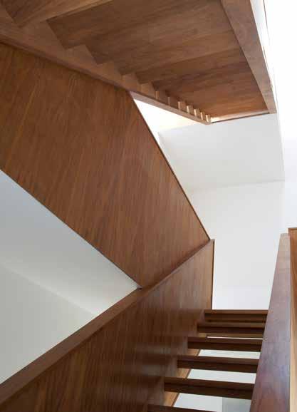

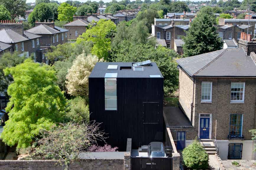
174
© Ed Reeve
Residential (Private)
SUNKEN HOUSE/ED’S SHED
Ed ReeveSunken House, known affectionately as ‘Ed’s shed’, is a three-storey family home in North Hackney designed for photographer Ed Reeves. The design of the home responds to its immediate context, drawing from the local architecture of Victorian terraced houses and warehouse workshops.
Viewed from the street, the house appears to have the same habitable volume as the adjacent semi-detached villa, and the flat roof of the cuboid structure aligns with the warehouse opposite. However Ed’s shed has been sunk an entire storey to maximize the interior space. Standing in an excavated courtyard, which is not overlooked by the adjacent buildings, the main living space is located at basement level. The bedrooms are on the first floor, and there is a large studio on the second floor which benefits from a view of other people’s gardens without intruding on their privacy.
All façades of the house and the horizontal surface of the concrete patio are clad in a timber rainscreen of dark stained cedar.
The CLT upper levels, which sit on the excavated concrete lower floor were erected in a single week, substantially reducing the overall construction program.
175 LOCATION EMBODIED CARBON WITHIN TIMBER* CLT FACT STRUCTURE TYPE OVERALL CONSTRUCTION TIMBER ASSEMBLY TIMBER VOLUME MAIN CONTRACTOR TIMBER MANUFACTURER TIMBER CONTRACTOR TIMBER ENGINEER
ENGINEER ARCHITECT CONSTRUCTION COST HEIGHT / STOREYS Pure CLT Ed Reeve Techniker Undisclosed CLT assembly in one week Züblin Timber (formerly Finnforest Merk) 2,600 ft 3 (74 m 3) Adjaye Associates 52 weeks 1 week Eurban Eurban 23 ft (6.9 m) / 3 storeys -46 tons (-42 tonnes) CO 2 e
London Borough of Hackney Section
STRUCTURAL
2007

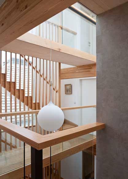
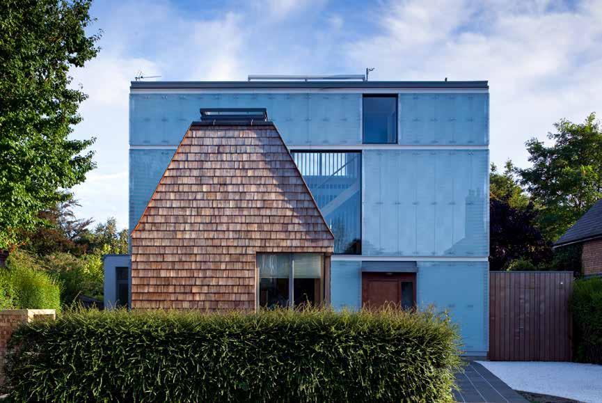
176
© David Butler
Residential (Private)
CAVENDISH AVENUE
Hugo Macey & Hajni Elias
Cavendish Avenue house re-interprets the suburban villa, replacing a 1930s detached home in a tree-lined suburban enclave of Victorian and Edwardian detached houses close to the centre of Cambridge.
The building is constructed of CLT panels, supported by glulam beams and columns. The north-facing front elevation is clad in a semi-reflective patterned glass rain-screen, with a pitch-roofed shingled structure extending into the front lawn from the first storey. Enclosed separately from the main house, this intimate, timber-lined music room references the surrounding architecture.
A skeleton of the glulam beam structure extends to the rear to form a solar shading portico in the garden. Roof-lights can be opened for ventilation, whilst large sail rigs hung across the portico beams on the rear façade provide shade and prevent the house from over-heating.
The solid floors act as a thermal heatsink, minimizing the need for additional heating. The dark basalt tiles on the internal ground floor absorb heat during the day, which is slowly released overnight. A ground-source heat pump provides hot water and the minimal heating required.
The building uses less than the target of 4,750 Btu/ft 2 (15 kWh/m 2) for space heating – equivalent to German Passivhaus standards.
EMBODIED CARBON WITHIN TIMBER*
-45 tons (-41 tonnes) CO 2 e
CLT FACT STRUCTURE TYPE
177 LOCATION HEIGHT / STOREYS ARCHITECT CONSTRUCTION COST STRUCTURAL ENGINEER TIMBER ENGINEER TIMBER MANUFACTURER TIMBER CONTRACTOR MAIN CONTRACTOR
OVERALL CONSTRUCTION TIMBER ASSEMBLY TIMBER VOLUME Pure Timber Cambridge Building Company Measured in-use energy efficiency meets Passivhaus standards KLH UK 43 weeks 1 week 2,600 ft 3 (74 m 3) KLH Massivholz Ramboll Ramboll / Whitbybird Undisclosed Mole Architects 28 ft (8.4 m) / 3 storeys Cambridge 2008 Section
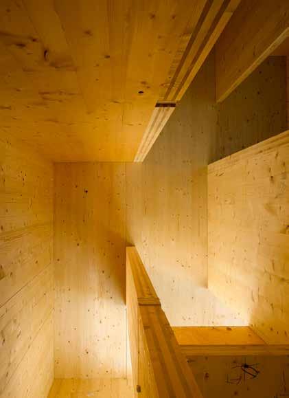
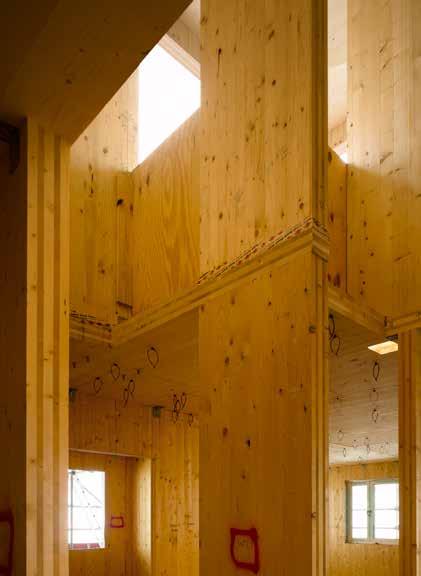
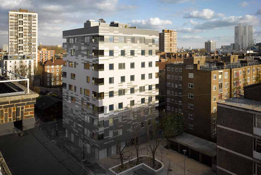
178
© Will Pryce
LOCATION
London Borough of Hackney
HEIGHT / STOREYS
95 ft (29 m) / 9 storeys
CONSTRUCTION COST
£3.86 million
ARCHITECT
Waugh Thistleton Architects
STRUCTURAL ENGINEER
Techniker / Jenkins & Potter
TIMBER ENGINEER
Techniker / KLH UK
TIMBER CONTRACTOR
Residential STADTHAUS/MURRAY GROVE
Metropolitan Housing Trust / Telford Homes PLC
This was first tall building using engineered timber, and was the tallest timber residential structure in the world at the time of completion. The entire structure above first floor slab is comprised of CLT panels, with all walls, floor slabs and lift cores formed in solid timber which act together, like a honeycomb, providing a very stable and efficient building.
The building form is an extrusion of the site footprint to 9 storeys, which was largely predetermined by planning constraints. The client required separate entrances for affordable and private apartments which resulted in a mirrored ground floor plan from east to west. Different layouts are used throughout the building to accommodate a mix of family units and smaller apartments. These are facilitated through the use of load-bearing CLT panels, which form party walls and some internal partitions.
The distinctive pixelated façade is made up of 2,500 individual panels in three hues, which are arranged to capture how shadows fall across the building. The lightweight wood-pulp cladding avoids adding unnecessary bulk to the tower.
TIMBER MANUFACTURER
KLH Massivholz
MAIN CONTRACTOR
Telford Homes
TIMBER VOLUME
31,800 ft 3 (901 m 3)
TIMBER ASSEMBLY
9 weeks
OVERALL CONSTRUCTION
49 weeks
In creating a world first, the design team, contractor and timber supplier had to collaborate closely and work together with the client to overcome regulatory hurdles and demonstrate the resilience and safety of the building. This exemplar project has spearheaded the introduction of CLT in the UK, and pioneered an international movement in tall timber construction.
STRUCTURE TYPE
Pure CLT
EMBODIED CARBON WITHIN TIMBER*
KLH UK -557 tons (-505 tonnes) CO 2 e
CLT FACT
If built today it could use 30% less timber due to modern analytical tools
179
Axonometric of CLT
2009


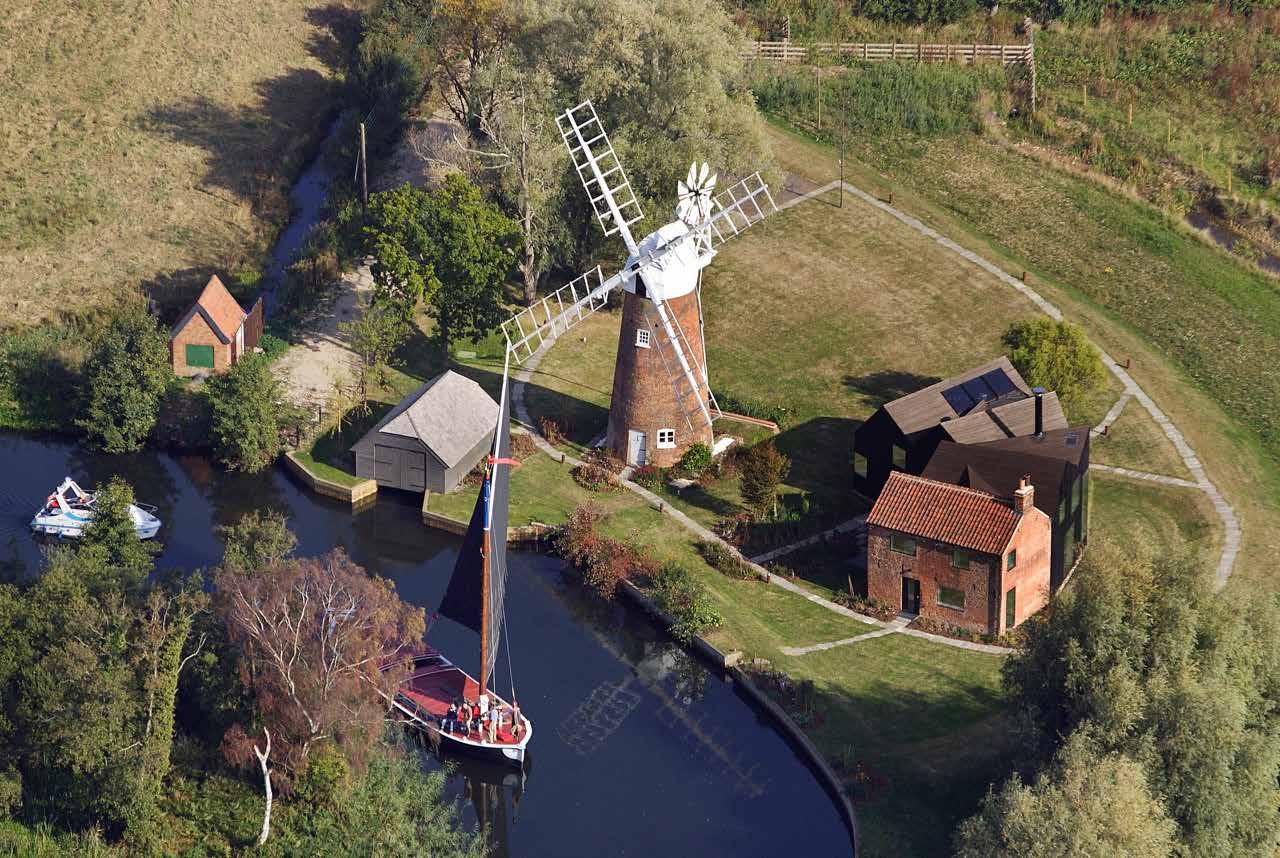
180
© ACME © ACME
Residential (Private) Private Client HUNSETT MILL
The extension to this 19th century mill keeper’s cottage sits adjacent to the Grade II listed mill. Since the end of its working life in 1900, the house has been a private residence, extended with a series of ill-conceived add-ons which had caused subsidence and repeated flooding. When further space was required it was decided to re-instate the house to its original proportions with only a single extension to one side.
The extension is designed as a shadow of the existing house which retreats behind the listed mill. Clad in dark charred cedar boards the geometry of the extension appears ambiguous from afar. A series of undulating pitched roofs mimic the local vernacular.
The extension is made entirely from CLT which is exposed as interior finish. The unique geometry of the roof forms a stiff plane from which the first floor is hung, allowing for a large, open-plan ground floor.
The design considered its embodied energy and method of construction alongside the efficiency during occupation. In addition to the timber structure, ground source heat pumps, passive solar heating and an independent water-well make the house almost completely self-sufficient, creating a home that is aesthetically innovative, responsive to contemporary needs and sensitive to its surroundings.
181 LOCATION HEIGHT / STOREYS ARCHITECT CONSTRUCTION COST STRUCTURAL ENGINEER TIMBER ENGINEER TIMBER MANUFACTURER TIMBER CONTRACTOR
CARBON WITHIN TIMBER* CLT FACT STRUCTURE TYPE
CONSTRUCTION TIMBER ASSEMBLY TIMBER VOLUME MAIN CONTRACTOR Pure CLT Willow Builders / Eurban / Nuttall Open ground floor space created by hanging first floor plate Eurban 43 weeks 2 weeks -51 tons (-46 tonnes) CO 2 e 2,900 ft 3 (82 m 3) Züblin Timber (formerly Finnforest Merk) Eurban / AKT II AKT II Undisclosed ACME 21 ft (6.5 m) / 2 storeys 2009 Stalham,Norfolk
CLT Panel Diagram
EMBODIED
OVERALL
Isonometric
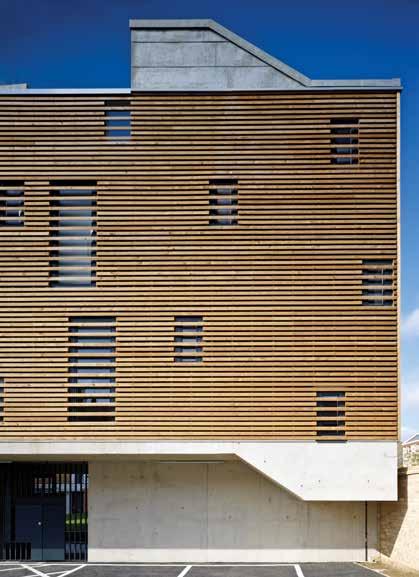

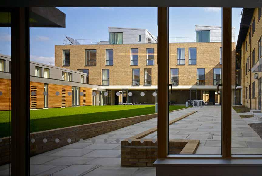
182
© Tim Soar
Residential (Education) St Catherines College Development Ltd RUSSELL STREET
Cambridge, Cambridgeshire
CONSTRUCTION COST HEIGHT
million
ARCHITECT
5th Studio 39 ft (12 m) / 1.5 - 4 storeys
STRUCTURAL ENGINEER
Michael Hadi Associates
TIMBER ENGINEER
Michael Hadi Associates / Eurban
TIMBER CONTRACTOR
TIMBER MANUFACTURER
MAIN CONTRACTOR
TIMBER VOLUME
TIMBER ASSEMBLY
OVERALL CONSTRUCTION
While the city fringe college site offers a generous garden space, the poor positioning of the original building and overlooking caused by adjacent plots had created awkward relationships between buildings. This project adds twenty-two rooms and capsule apartments, re-focusing the existing buildings around a green garden court to create an intimate college setting that politely screens adjacent sites.
Site constraints dictated it was necessary to build up to an irregular boundary on three sides. The choice of CLT for the structure meant that through the precision manufacturing process every dimension could be exactly specified. The relatively slender structural profiles of the floor, roof and wall panels (with no downstand beams or ribbed structures) maximized the useable volume of the new building.
Newly built rooms face the courtyard and are brought together by generous corridors, echoing the traditional architecture of Cambridge colleges. The ground floor duplex rooms that define the courtyard edges are ingeniously planned in cross section, allowing double height space, natural light sources and cross ventilation to each room. Selectively exposed CLT offers a warm and aesthetically pleasing finish; suitably robust and requiring minimal maintenance or decoration. The exposed timber buffers moisture and VOC’s, contributing to high air quality and comfort conditions throughout the building.
STRUCTURE TYPE
EMBODIED CARBON WITHIN TIMBER*
CLT FACT
183 LOCATION
Pure CLT SDC
of construction enabled tight program to be met Eurban Section 50 weeks 4 weeks -161 tons (-146 tonnes) CO 2 e
3
m 3)
/ STOREYS
Speed
8,800 ft
(250
Schilliger Holz
£2.6
2009
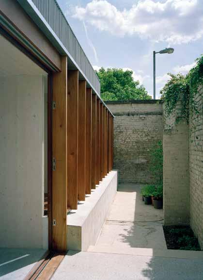
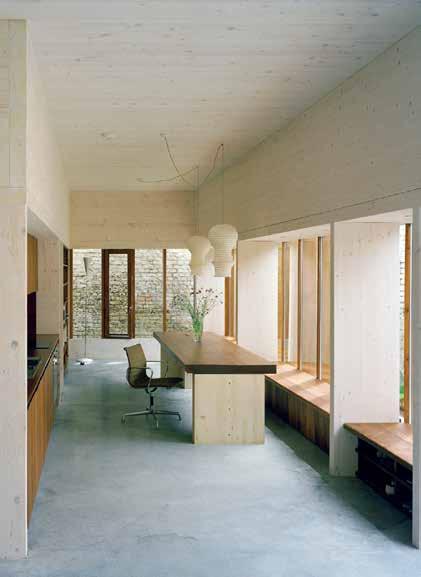

184
© David Grandorge
LOCATION
London Borough of Lewisham
HEIGHT / STOREYS
12 ft (3.7 m) / 1 storey
Residential (Private)
STRANGE HOUSE
Hugh Strange / Adriana FerlautaSituated within the brick walls of an old pub yard the two bedroom house and adjacent studio occupy the site extensively.
While only 830ft 2, the house feels deceptively large with spaces stretching 10ft high and, 36ft long, enfilade rooms, and framed views. A narrow space between the house and perimeter wall links the inside and outside spaces.
£170,000
CONSTRUCTION COST ARCHITECT
Hugh Strange Architects
STRUCTURAL ENGINEER
Price & Myers
TIMBER ENGINEER
Eurban
TIMBER CONTRACTOR
The structure is formed of CLT panels that were craned over the existing wall and fixed into place over the period of just one week. White-washed and left exposed internally, the primary structure has a strong relationship with the secondary timber fit-out. Glass is sandwiched between exposed structural timber and hardwood frames to form windows. Internal doors are face-fixed to structural openings, and the kitchen, cupboards, seating and shelving units sit within recesses formed in the structural frame.
TIMBER MANUFACTURER
Eurban Schilliger Holz
MAIN CONTRACTOR
Every space has the same palette of simple materials: concrete floors, white-washed CLT walls and ceilings; dark hardwood windows, doors and furniture.
OVERALL CONSTRUCTION
EMBODIED CARBON
CLT could be craned in over the existing walls -13 tons (-12 tonnes) CO

2010
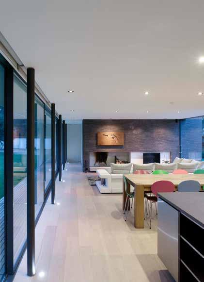
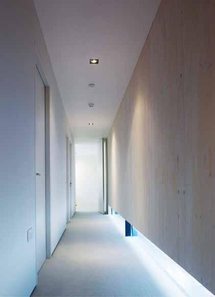
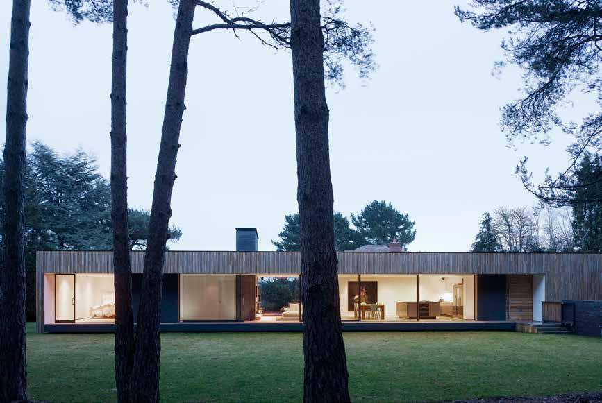
186
© James Morris
LOCATION
13 - 17 ft (3.9 - 5.3 m) / 2 storeys
CONSTRUCTION COST
HEIGHT / STOREYS ARCHITECT
The house replaces a large suburban style two-storey house in a rural site within the New Forest. The design responds to both the client’s desire to live in close contact with nature and the idea of making the house invisible from the public realm to deal with restrictive local planning policy.
John Pardey Architects
STRUCTURAL ENGINEER
Ramboll £640,000
TIMBER ENGINEER
KLH UK
TIMBER CONTRACTOR
KLH UK
TIMBER MANUFACTURER
KLH Massivholz
MAIN CONTRACTOR
NFTS
TIMBER VOLUME
3,500 ft 3 (99 m 3)
TIMBER ASSEMBLY
43 weeks 1 week
This has resulted in a long, low pavilion that ‘touches the earth lightly’. Orientated north-south the rectangular form provides three bedrooms that open up to the east and morning light. A large open-plan living-diningkitchen area, and a master bedroom suite and study, open to the west with views into a pine copse. A brick chimney and hearth, built in Danish brick, anchors this delicate pavilion to the site.
The low-impact design is extended to the materials and systems used in its construction. The superstructure of the house is CLT, clad in a sweet chestnut timber façade. A ground-source heat pump, rainwater recycling and high levels of insulation further reduce the impact of the house on the environment.
STRUCTURE TYPE
OVERALL CONSTRUCTION Hybrid
EMBODIED CARBON WITHIN TIMBER*
-63 tons (-58 tonnes) CO 2 e
CLT FACT
CLT used for continuation of low-impact design
187
Section
2010 Residential (Private) Private Client WATSON HOUSE
Boldre, Hampshire
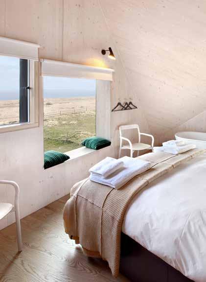
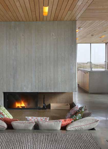
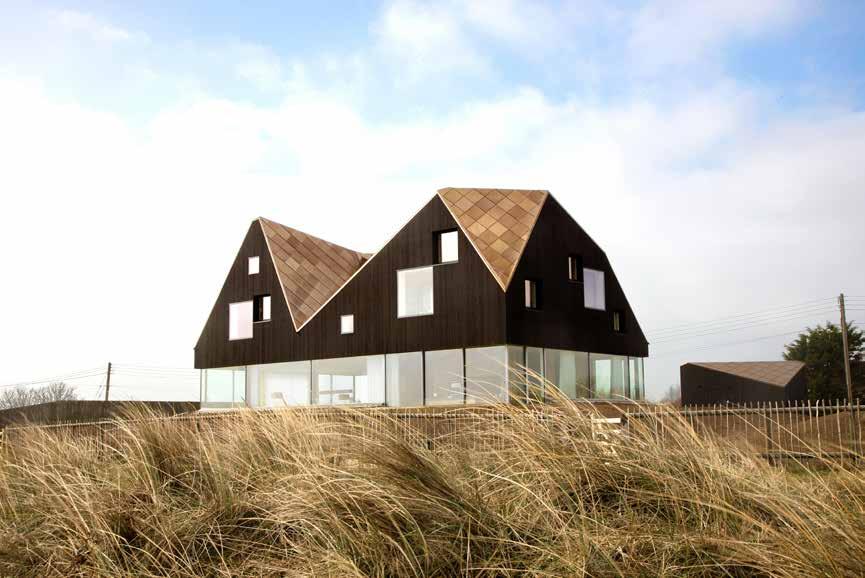
188
© Chris Wright for Living Architecture
Jarmund Vigsnaes / Mole Architects
Residential (Private) Living Architecture DUNE HOUSE
The house, designed for use as a holiday home, is situated on the Suffolk coast overlooking the sea. Relating to the typical British seaside strip of houses, the roofscape, with an eclectic range of pitches and dormer windows, brings to mind a romantic memory of holidays at bed and breakfasts while traveling through the UK.
TIMBER ENGINEER
TIMBER CONTRACTOR
TIMBER MANUFACTURER
MAIN CONTRACTOR
TIMBER VOLUME
TIMBER ASSEMBLY
OVERALL CONSTRUCTION
STRUCTURAL ENGINEER Hybrid Willow Builders
The building is designed to be both a refuge against the North Sea, and a beach-side house open to the sandy dunes. The architecture of the ground floor is quite distinct from that of the upper storey. At ground level the open plan living area and terraces are set into the dunes which provide protection from the strong winds. Sliding doors at the corners bring the outside in, and the glazed walls allow for wide views and emphasize the floating appearance of the top floor.
While the materiality of the ground floor; concrete, glass and aluminum, relates to the mass of the ground, the upper floor, which houses four bedrooms, is a CLT construction exposed internally with dark cladding externally reminiscent of existing gables and sheds found within the area. The use of CLT facilitated the construction of the elaborate roof.
A striking and structurally complex house, the load of the upper floor is supported by a reinforced cantilevered concrete slab.
STRUCTURE TYPE
EMBODIED CARBON WITHIN TIMBER*
CLT FACT
CLT construction was unaffected by the strong North Sea winds engineersHRW (formerly Jane Wernick Associates)
189 LOCATION
HEIGHT / STOREYS ARCHITECT CONSTRUCTION COST
Eurban Undisclosed
e Section 2010
Eurban
26 ft (7.8 m) / 2 storeys Thorpeness, Suffolk Schilliger Holz 2,100 ft 3 (60 m 3) 1 week 48 weeks -38 tons (-35 tonnes) CO 2
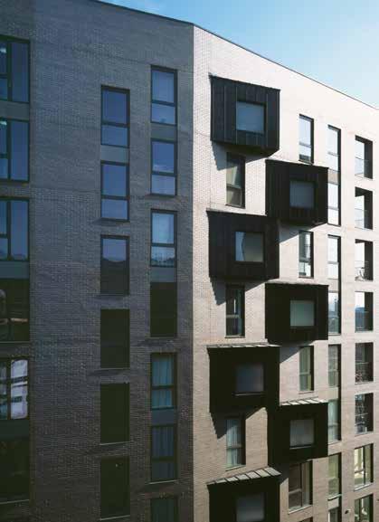
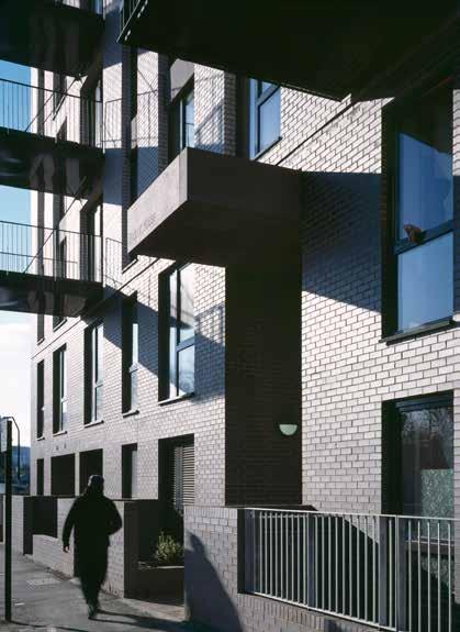
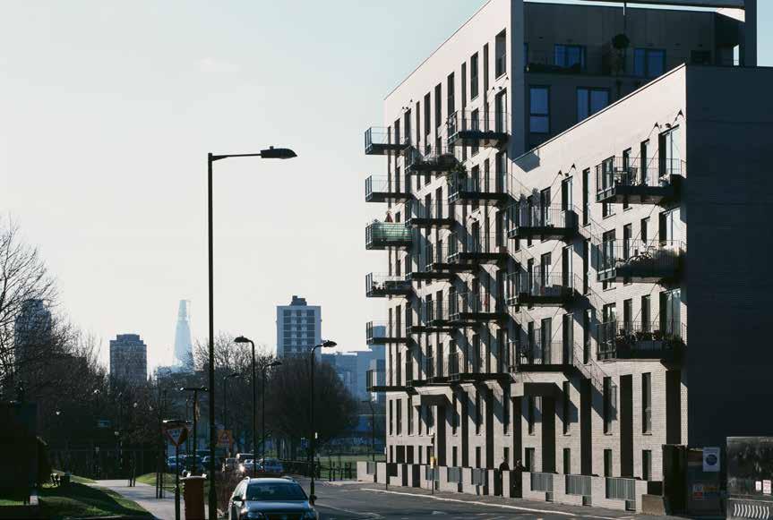
190
© Karakusevic Carson Architects
© Ioana Marinescu
© Ioana Marinescu
London Borough of Hackney LOCATION
HEIGHT / STOREYS
84 ft (25.6 m) / 5-8 storeys
CONSTRUCTION COST
£6 million
Residential Hackney Council BRIDPORT HOUSE
Bridport House is the first phase of the wider Colville Estate Regeneration program which will replace 438 existing homes with over 900 new residences over approximately 20 years.
Karakusevic Carson Architects
STRUCTURAL ENGINEER ARCHITECT
Peter Brett Associates
TIMBER ENGINEER
The building is designed as an eight and five storey urban block, on a narrow and constrained site, replacing a 1960s building that had turned its back on the street. The new Bridport House creates a street frontage onto the refurbished Shoreditch Park and starts to define the emerging street pattern of the masterplan.
TIMBER CONTRACTOR
TIMBER MANUFACTURER
Stora Enso
MAIN CONTRACTOR
Willmott Dixon Eurban Eurban
TIMBER VOLUME
55,700 ft 3 (1,576 m 3)
TIMBER ASSEMBLY
12 weeks
OVERALL CONSTRUCTION
56 weeks
One of London’s main drainage tunnels runs directly underneath the building meaning that little extra weight could be exerted while the capacity of the block had to be doubled from 21 to 41 new homes. CLT offered a solution, the lightweight quality of timber allowing for twice as many units as the previous block to be built over the large Victorian sewer below. The structure was designed so that the load-bearing CLT panels are placed in a variety of positions on each floor, spreading the load.
The use of CLT for the structure also guaranteed the speed of construction which was essential to achieve the ambitious hand-over date to meet the Homes and Communities Agency’s strict funding rules.
STRUCTURE TYPE
Pure CLT
EMBODIED CARBON WITHIN TIMBER*
First multi storey building to use CLT from the ground up -988 tons (-896 tonnes) CO 2 e
CLT FACT
191
2011 Section
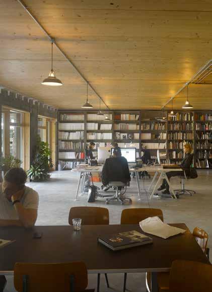
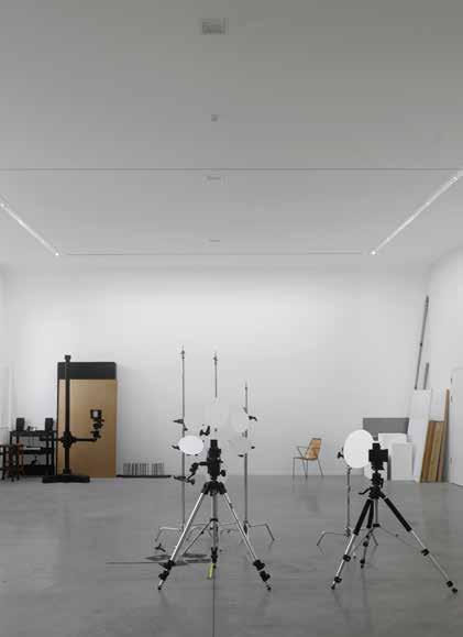
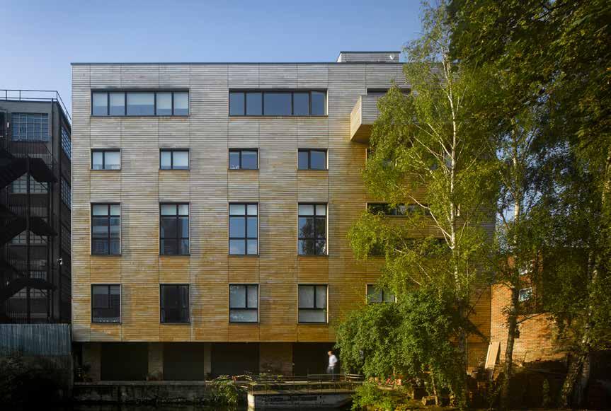
192
© Will Pryce
LOCATION
London Borough of Hackney
HEIGHT / STOREYS
67 ft (20.5 m) / 7 storeys
CONSTRUCTION COST
£2 million
ARCHITECT
Waugh Thistleton Architects
STRUCTURAL ENGINEER
TIMBER ENGINEER
KLH UK
TIMBER CONTRACTOR Akera Engineers
KLH UK
TIMBER MANUFACTURER
KLH Massivholz
MAIN CONTRACTOR
Jerram Falkus
TIMBER VOLUME
17,600 ft 3 (499 m 3)
TIMBER ASSEMBLY
5 weeks
OVERALL CONSTRUCTION
104 weeks
STRUCTURE TYPE
Pure Timber
EMBODIED CARBON WITHIN TIMBER*
-310 tons (-281 tonnes) CO 2 e
CLT FACT
Timber walls between the flats act as giant trusses above the studio
WHITMORE ROAD
Residential Whitmore Road LLP
This mixed use building is located adjacent to the Whitmore Road Bridge over Regent’s Canal. It provides the four-client co-operative with two floors of office space, a double-height photographic studio and three triplex apartments at the top of the building that open onto generous roof terraces overlooking the canal.
CLT was the obvious structural solution for this tight urban site. The building footprint extends over almost the entire site area, bounded on two sides by buildings, and a third by the canal. It was craned into place directly from the street in only 5 weeks.
The CLT structure sits on a concrete lower ground floor which acts as a plinth. At the centre of the building, the double height studio spans 30ft and stretches to 79ft of open column-free space. This was achieved using the party walls above the space as deep beams and the north and south façades as giant trusses. Glulam beams on the north façade help spread the loads down this elevation and minimize deflection.
The building is clad in British sweet chestnut, a material traditionally used to clad barns. It is a robust, stable timber which is lightweight, strong and durable. It is less prone to movement, distortion or splitting than other timber species. Similar in color to oak, it has weathered to a natural silver color over time.
193
2012
Section
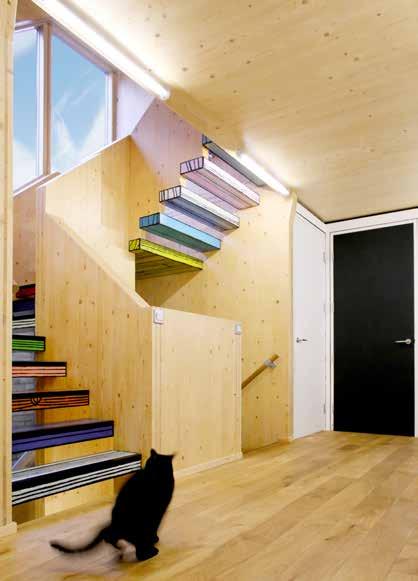

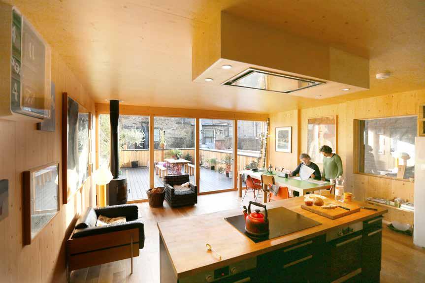
194
© Alex de Rijke / dRMM
LOCATION
London Borough of Tower Hamlets
HEIGHT / STOREYS
39 ft (12 m) / 3 storeys
CONSTRUCTION COST
Residential (Private)
WOODBLOCK HOUSE
Richard Woods & Jess Spanyol
Artist Richard Woods approached dRMM with the desire to create a studio, office and home for his family entirely out of wood. Collaboration between the architect and client has resulted in a simple design with both the aesthetic and structural materiality of the house defined by timber.
ARCHITECT
Undisclosed dRMM
STRUCTURAL ENGINEER
Timber First
TIMBER ENGINEER
Timber First/Züblin Timber
TIMBER CONTRACTOR
Züblin Timber (formerly Finnforest Merk)
TIMBER MANUFACTURER
Züblin Timber (formerly Finnforest Merk)
MAIN CONTRACTOR
Cape Construction
TIMBER VOLUME
The house is formed of two cuboid structures resting atop one another. A large workshop and printing studio space occupy the ground floor at a north-facing incline, with separate south-facing living accommodation stacked above. To demarcate the public and private spaces of the building, the studio is clad in unpainted, vertically aligned larch, whilst the southfacing home on the upper floors is identified by horizontal strips of painted plywood. Woods' signature cartoon-esque, brightly-painted wood textile print is used on the plywood façade, and to adorn the internal staircase that extends through the central elevation. These bright, primary hues create a striking contrast with the interior finish of exposed CLT.
Both client and architect were attracted to timber due to its environmental credentials and aesthetic characteristics. Nestled between its neighboring buildings of brick and concrete, Woodblock House demonstrates the potential of CLT infill within an urban residential setting.
TIMBER ASSEMBLY
2 weeks
OVERALL CONSTRUCTION
34 weeks
STRUCTURE TYPE
Pure CLT
EMBODIED CARBON WITHIN TIMBER*
-76 tons (-69 tonnes) CO 2 e 4,300 ft 3 (121 m 3)
CLT FACT
One of the first all timber houses built in central London since the 1666 Great Fire
195
2013
Section
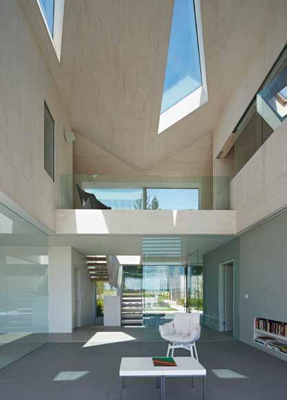
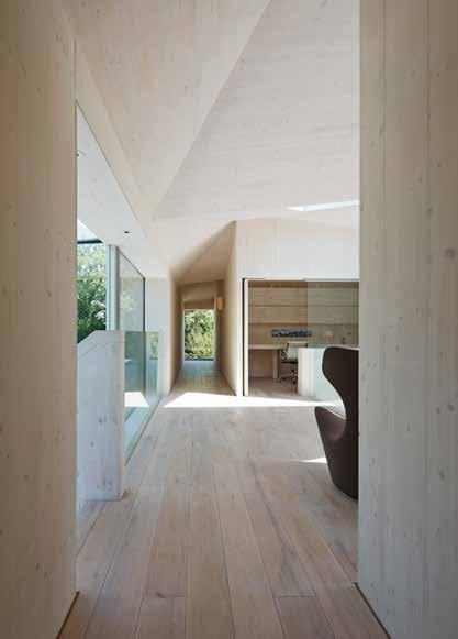
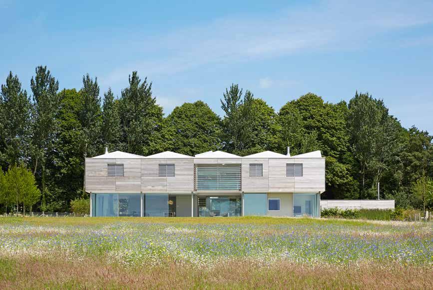
196
© Paul Riddle
2013 Residential (Private)
Private Client SUSSEX HOUSE
LOCATION
South Downs, Sussex
21 ft (6.5 m) / 2 storeys
CONSTRUCTION COST
Undisclosed
HEIGHT / STOREYS ARCHITECT
Wilkinson King
STRUCTURAL ENGINEER
Packman Lucas
TIMBER ENGINEER
Pryce & Myers / KLH UK
TIMBER CONTRACTOR
KLH UK
TIMBER MANUFACTURER
KLH Massivholz
MAIN CONTRACTOR
This house is inspired by its rural context and exceptional position overlooking the South Downs. The building is conceived as a series of layers, which echo the horizontality of the meadows and hills as they recede into the distance.
The ground floor is glazed giving panoramic views from the living spaces and can be fully opened up to access the external terraces. The first floor overhangs to provide summer shading. A double height reception space, with exposed CLT walls and ceiling, connects the two floors.
The first floor and roof are assembled from 143 CLT panels. The roof form is made from a series of tilted triangular planes, forming a folded, undulating surface mimicking the distant hills. CLT presented itself as the most structurally efficient and lowest cost option to achieve the spans required.
The internal timber surfaces are exposed bringing a warm, tactile quality to the bedrooms and circulation spaces and providing a harmony between the house and its environs.
The first floor is clad in cedar, weathering to match the color of the surrounding trees. Inline louvered shutters are concealed within the timber façade to prevent summer heat gain from the south facing windows.
TIMBER VOLUME
2,300 ft 3 (65 m 3)
TIMBER ASSEMBLY
2 weeks
OVERALL CONSTRUCTION
78 weeks
STRUCTURE TYPE
Westridge Construction Hybrid
EMBODIED CARBON WITHIN TIMBER*
-39 tons (-36 tonnes) CO 2 e
CLT FACT
CLT chosen for ease and low cost of forming complex geometric roof
197
Section
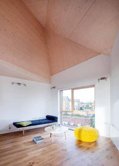

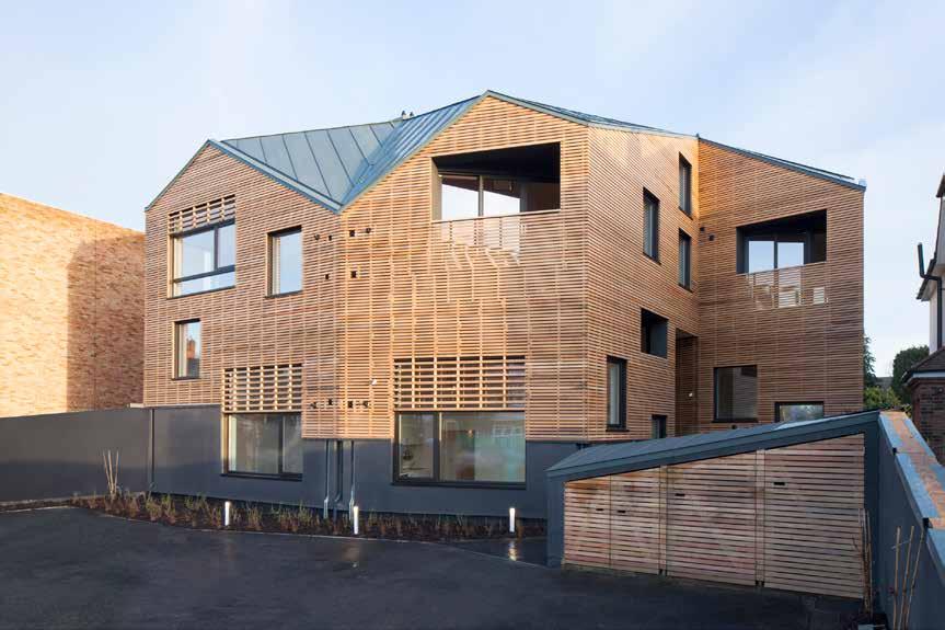
198
© Peter Guenzel
2014
Residential MAZARIN HOUSE
KTN Group
London Borough of Redbridge
HEIGHT / STOREYS
35 ft (10.8 m) / 4 storeys
CONSTRUCTION COST
ARCHITECT
Arboreal Architecture
STRUCTURAL ENGINEER
Structure Workshop Undisclosed
TIMBER ENGINEER
Mazarin House is a block of 6 two-bedroom flats in Woodford, East London. The local area comprises detached 1930s homes and 1970s blocks of flats. In response to this mixed urban setting the building was designed as a hybrid between a block of flats and a detached townhouse. This was achieved by combining the density of a block of flats with the massing and proportions of a detached house. The width of the front façade was matched to the adjacent houses and the roof profile echoed the double-bay fronted properties nearby. Four storeys of accommodation were built on a site where only three had previously been possible, whilst the mass of the building was sculpted to respond to allow light and views to reach neighbors.
TIMBER CONTRACTOR
KLH Massivholz KLH UK
To optimize the available space, light and views a non-orthogonal geometry was used. Without the restriction of designing only in right angles the building could respond more sensitively to its constraints. All 6 flats achieved southfacing, double-height living spaces and generous balconies.
TIMBER MANUFACTURER
MAIN CONTRACTOR
TIMBER VOLUME
8,500 ft 3 (242 m 3)
TIMBER ASSEMBLY
OVERALL CONSTRUCTION
The non-orthogonal design was made possible by the CLT construction system. The CLT panels form the walls, floors and roof and were cut by computer numerical control (CNC) directly from a 3D computer model. This digital fabrication allowed the many complex angles to be easily constructed on site from a precise kit of parts.
STRUCTURE TYPE
Pure CLT Hutton Group
EMBODIED CARBON WITHIN TIMBER*
CLT FACT
Digital fabrication allowed for nonorthogonal geometries KLH UK 53 weeks 5.5 weeks -149 tons (-135 tonnes) CO 2 e
199
LOCATION
Second Floor Plan

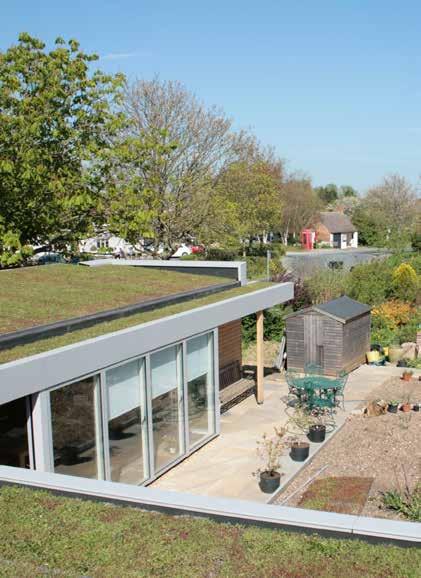
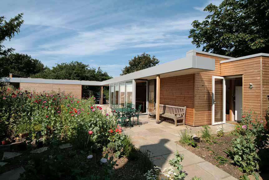
200
© David Grindley Architects
2014
Residential (Private)
NURSES COTTAGE
Jim Morrison & Jenny MeltonLOCATION
Milton Keynes, Buckinghamshire
HEIGHT / STOREYS
10 ft (3.2 m) / 1 storey
CONSTRUCTION COST
£150,000
ARCHITECT
David Grindley Architects
STRUCTURAL ENGINEER
KMG Tapsell Wade
TIMBER ENGINEER
KMG Tapsell Wade
TIMBER CONTRACTOR
KLH UK
TIMBER MANUFACTURER
KLH Massivholz
MAIN CONTRACTOR
Richard Lyons
TIMBER VOLUME
1,000 ft 3 (29 m 3)
TIMBER ASSEMBLY
3 days
OVERALL CONSTRUCTION
52 weeks
The scheme was conceived as an invisible building disguised as a site boundary adjacent to a listed thatched roof cottage. The new garden room and workshop is set in the curtilage of the Grade II listed Nurses Cottage in the Milton Keynes Village conservation area. Designed to respect the setting of the listed building, the new home was deliberately kept to a single storey with a low pitched green roof.
The building is comprised of two single-storey wings articulated in an ‘L’ shape courtyard arrangement. In conjunction with the existing cottage this plan forms a new private garden at its centre. The design is clearly articulated into its constituent elements: enclosure; floating roof and glazed colonnade.
The principal material used in the construction of the building is CLT, which is exposed internally and covered with a clear, white finish. The glazed clerestory between the roof and outer enclosing wall reflects light onto the exposed CLT roof panels.
Externally, the building is clad in heat-treated timber weather boarding with an aluminium coping. A planted sedum roof provides thermal mass and attenuation to storm water, while heat is provided via a ground-source pump.
STRUCTURE TYPE
Pure CLT
EMBODIED CARBON WITHIN TIMBER*
-17 tons (-16 tonnes) CO 2 e
CLT FACT
Client inspired to use CLT after seeing it at the architect’s offices
201
Ground Floor Plan
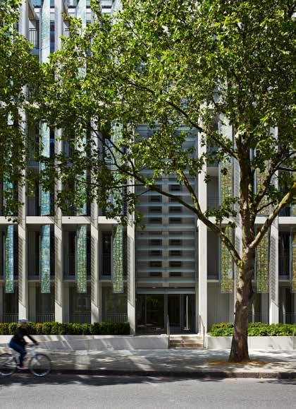
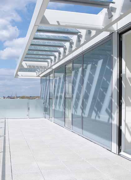

202
© Mark Polyblank © Dennis Gilbert
© Dennis Gilbert
Royal Borough of Kensington & Chelsea
75 ft (23 m) / 7 storeys
CONSTRUCTION
£9.6 million
ARCHITECT
Horden Cherry Lee Architects
STRUCTURAL ENGINEER
Price & Myers
TIMBER ENGINEER
TIMBER CONTRACTOR
TIMBER MANUFACTURER
MAIN CONTRACTOR
TIMBER VOLUME
TIMBER ASSEMBLY
OVERALL CONSTRUCTION
KINGSGATE HOUSE
Residential De Vere Gardens / Catalyst Housing
Kingsgate House is a modern design for affordable housing that integrates its sustainable and environmental responsibilities into the architecture. The building provides 43 new homes on a prominent site in Kensington.
The design form, proportions and column spacing were established from careful analysis of the local historic context, a conservation area made up largely of stuccoed Victorian estates.
The façade is formed of vertically integrated solar shutters that respond to orientation and provide privacy for residents. The multi-toned, phosphorescent green of the PVC cells recalls the colors of the surrounding trees. Behind the shutters each apartment has its own recessed balcony, which provide external space that is not exposed to the heavy traffic on the adjacent main road. Energy created by the PV panels is fed back into the grid.
Selected for its environmental credentials, the use of CLT in this project enabled the reuse of existing foundations on site due to the reduction in weight as compared to a traditional structure, saving time and money. Kingsgate House was the first major building project to be PEFC certified demonstrating that all the timber used was both sustainable and ethically sourced.
STRUCTURE TYPE
CLT FACT
203
LOCATION
EMBODIED CARBON WITHIN TIMBER*
Pure CLT
major building to be PEFC certified KLH UK Typical Floor Plan in Context 2014 78 weeks 12 weeks 679 tons (-616 tonnes) CO 2 e
m 3)
COST HEIGHT / STOREYS
Willmott Dixon First
38,600 ft 3 (1,092
KLH Massivholz KLH UK
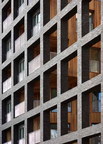
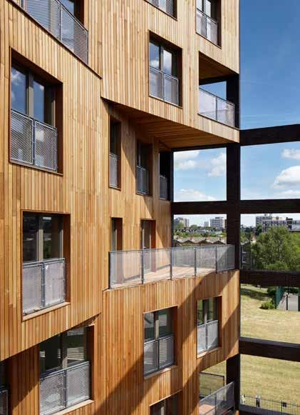
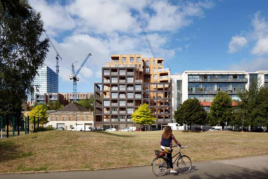
204
© Jack Hobhouse
LOCATION
London Borough of Hackney
HEIGHT / STOREYS
110 ft (33.5 m) / 10 storeys
CONSTRUCTION COST
£10.5 million
ARCHITECT
Residential Regal Homes WENLOCK CROSS
Wenlock Cross alters the traditional housing block to provide each apartment with daylight, beautiful views and external space on a tight urban site.
STRUCTURAL ENGINEER
Pringuer-James
TIMBER ENGINEER Hawkins\Brown
The twisted cruciform plan creates four elevations with direct visual connections to the City of London. The irregular, skewed cruciform ensures that all apartments have dual or triple aspect views with generous terraces, good natural ventilation, and avoids views to interior courtyards or lightwells. The angular plan also reduces residents’ perception of density from within the apartments. Surrounding the street-facing side of the block is a skeletal brick grid that gives the large external terraces a sense of privacy, and creates a striking silhouette when viewed from the street.
TIMBER CONTRACTOR
B & K Structures
TIMBER MANUFACTURER
Binderholz Engenuiti
MAIN CONTRACTOR
Eurobuild Properties
TIMBER VOLUME
46,400 ft 3 (1,313 m 3)
TIMBER ASSEMBLY
30 weeks
OVERALL CONSTRUCTION
108 weeks
A hybrid CLT and steel structure proved to be the most efficient way to realize this unique 10-storey building and uses the inherent strengths of each material to rationalize the main superstructure. The CLT elevations are clad in slatted western red cedar, whilst along the Wenlock Road elevation, a dark brick screen completes the street elevation making reference to the light industrial character of the conservation area.
Hackney Councils’s Timber First agenda encouraged the choice of CLT as the structural solution for this scheme. Upon its completion, Wenlock Cross was the tallest hybrid CLT building in the UK.
STRUCTURE TYPE
Hybrid
EMBODIED CARBON WITHIN TIMBER*
-788 tons (-715 tonnes) CO 2 e
CLT FACT
Hackney’s timber first initiative encouraged investigation into CLT
205
Second Floor Plan
2015
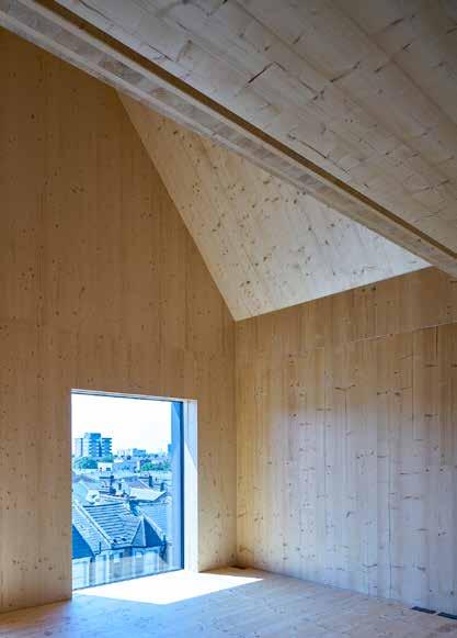
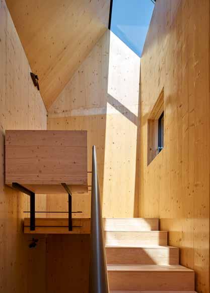
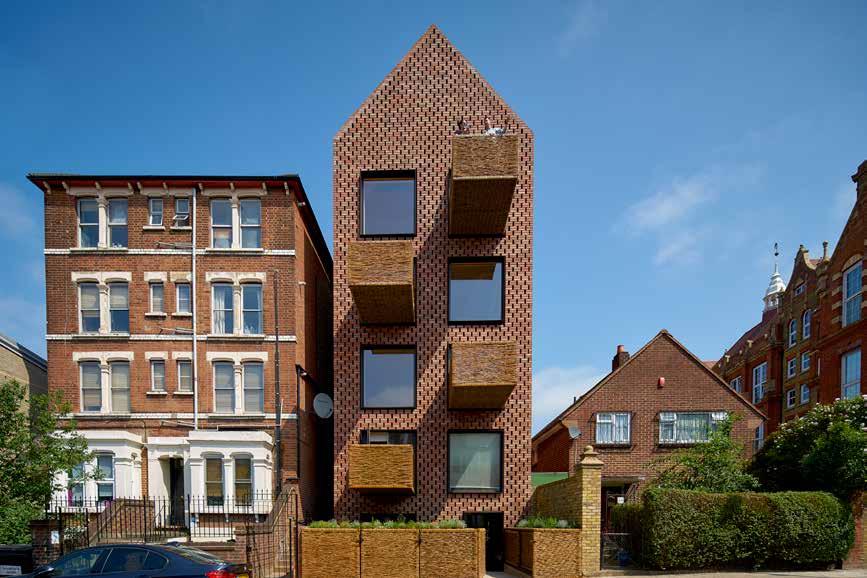
206
© Tim Soar
Residential Nick Grant BARRETTS GROVE
HEIGHT / STOREYS
CONSTRUCTION COST ARCHITECT
Groupwork + Amin Taha 59 ft (18 m) / 5 storeys London Borough of Hackney
STRUCTURAL ENGINEER
Webb Yates Engineers £1.27 million
TIMBER ENGINEER
TIMBER CONTRACTOR
TIMBER MANUFACTURER
MAIN CONTRACTOR
VOLUME
Accommodating six flats on a site between a Victorian Terrace and Edwardian School, the scheme echoes both the tall gables of the school and standalone villa typology of the terrace. The six-storey structure is made of load-bearing CLT panels, spanning up to 20ft. The roof is also solid CLT panels, carefully balanced against each other to create an open loft space within a traditionally pitched roof.
By positioning all services and build-ups on top of the floor slab, it has been possible to expose the CLT structure on all internal walls and ceilings allowing the material finish to provide the domestic character of the spaces. In addition to exposing its planar surface the cut edge is also left visible in order to describe its own make-up, structural depth and to reinforce if not reassure that the timber wall and ceiling finishes are not an effect.
Insulation with vapour barrier and protecting sheeting are applied to the outside face before a self-supporting brick rain-screen completes the exterior thermal and protective overcoat.
Using CLT as structure and finish removed the need for plasterboarded walls, suspended ceilings, cornices, skirtings, tiling and paint; reducing by 15% the embodied carbon of the building, and saving approximately £30,000 per flat.
EMBODIED CARBON WITHIN TIMBER*
-158 tons (-144 tonnes) CO 2 e
CLT FACT STRUCTURE TYPE
207 LOCATION
TIMBER
TIMBER
OVERALL
Pure CLT Ecore
Egoin
2
Section and Detail 52
Egoin Egoin
ASSEMBLY
CONSTRUCTION
Construction
£30,000 saving per flat
weeks
weeks 8,800 ft 3 (250 m 3)
2016

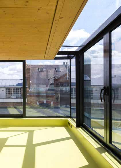
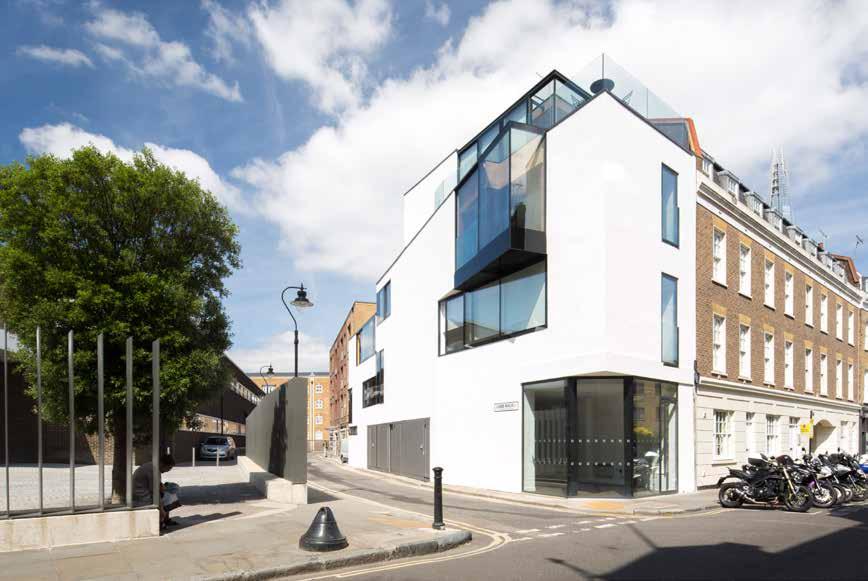
208
© Agnese Sanvito
Hampson Williams were commissioned to refurbish and extend the client’s existing home: a post-war building located in the Bermondsey Street Conservation area, providing a mix of residential, commercial and mixed use units. The concept was to create a bookend to the adjacent Georgian terrace, wrapping the form around the corner. Using the existing building as a starting point, large windows were introduced giving open views across the White Cube courtyard and providing south-facing sunlight.
Externally there is a simple, industrial-style box formed of planes with robust materials and clean lines retaining the white rendered aesthetic of the existing building as a base material. Large windows, placed at irregular intervals across the exterior, are defined by thick, black borders creating a striking street front façade.
These clean lines and industrial materials are continued internally with the exposed CLT timber structure bringing a softer residential feel and adding warmth to the spaces.
CLT was selected primarily to reduce costs – the lightweight material not requiring additional foundations. The speed of construction also lent itself to this tight urban site, limiting road closures and storage of materials on site.
209 LOCATION EMBODIED CARBON WITHIN TIMBER* CLT FACT STRUCTURE TYPE HEIGHT / STOREYS CONSTRUCTION
ARCHITECT TIMBER
COST
ENGINEER
TIMBER VOLUME TIMBER ASSEMBLY OVERALL CONSTRUCTION Pure CLT Cityline Construction Lightweight material eliminated need for additional foundations Eurban -35 tons (-31 tonnes) CO 2 e 52 weeks 2 weeks 1,900 ft 3 (55 m 3) Stora Enso Eurban Webb Yates Undisclosed Hampson Williams 39 ft (12 m) /4 storeys London Borough of Southwark 2015
STRUCTURAL ENGINEER TIMBER CONTRACTOR TIMBER MANUFACTURER MAIN CONTRACTOR
Section
(Private)
Client 142
Residential
Private
BERMONDSEY STREET
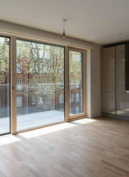
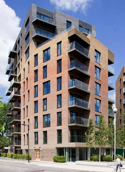
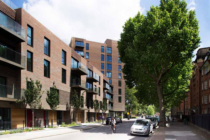
210
Alex de Rijke / dRMM
©
CONSTRUCTION COST HEIGHT
ARCHITECT
STRUCTURAL ENGINEER
TIMBER ENGINEER
TIMBER CONTRACTOR
TIMBER MANUFACTURER
MAIN CONTRACTOR
Residential Lendlease TRAFALGAR PLACE
Elephant and Castle suffered huge damage during WWII. The buildings that went up in the 1960s were often of poor quality; their huge structures created a place that found it hard to adapt and grow. The masterplan for the redevelopment of the Heygate Estate aims to restore this area to its former glory as a thriving, desirable place to live and visit.
Trafalgar Place is the first phase of this redevelopment and comprises 235 homes. Steering away from the alienating size of previous buildings the scheme provides variety through scale, with a mixture of mini-towers, apartment blocks and townhouses. Each apartment has been designed from the inside out, maximizing light and space, and all have either a garden, balcony or roof terrace.
Conceived as an opportunity for the client to test CLT as a long-term solution to building housing within the UK market, the two timber blocks are constructed principally of CLT, comprising CLT stair and lift shafts for stability and load-bearing façade and internal party walls. Load-bearing partition walls within apartments were avoided, with 21ft spans typically achieved allowing for future flexibility.
Whilst the quantum of timber is not the most significant, this project is a step-change in the delivery of large residential housing schemes.
EMBODIED CARBON WITHIN TIMBER*
CLT FACT
211 LOCATION
STRUCTURE TYPE OVERALL CONSTRUCTION TIMBER ASSEMBLY TIMBER VOLUME
Pure CLT Lendlease
Eurban Section 78 weeks 6 weeks -467 tons (-424 tonnes) CO 2 e 26,500 ft 3 (750 m 3) Stora Enso Eurban 2015 Robert
Group Undisclosed dRMM
ft (36 m) / 4 - 10 storeys
/ STOREYS
Building CLT alongside traditional methods can reduce the benefits
Bird
118
London Borough of Southwark
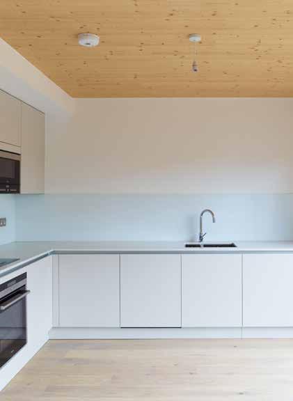
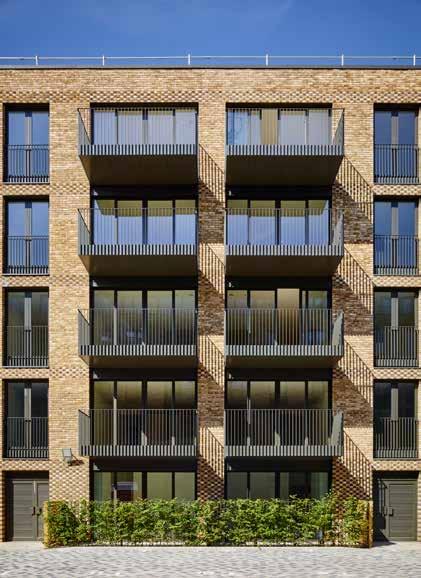
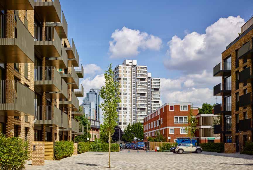
212
© Tim Soar
Residential Lendlease COBALT PLACE
63 ft (19.3 m) / 6 storeys London Borough of Wandsworth
CONSTRUCTION COST ARCHITECT
million
Allford Hall Monaghan Morris
STRUCTURAL ENGINEER
TIMBER ENGINEER
TIMBER CONTRACTOR
TIMBER MANUFACTURER
Cobalt Place is an enabling scheme, part funding a new school on the wider masterplan on the former Salesian College site. The scheme comprises 102 apartments split across two 5-6 storey buildings and two separate townhouses. The buildings are arranged to form a residential quarter with a central courtyard, opening up new views to the neighboring Sacred Heart church and increasing both visual and physical permeability.
The blocks are faced with two types of brick which recalls the Victorian houses of the surrounding area. Each storey is expressed with stack bond banding to add both a finer grain and improved legibility to the elevations. Internally, communal areas are defined by expanses of exposed fair-faced timber panels, revealing the structure as an aesthetic element, bringing natural warmth to the contemporary design of the new homes.
Initially designed as a concrete framed scheme, the decision to change the scheme to CLT was driven by the client. Chosen for its sound structural properties, construction efficiency and low environmental impact, the CLT structure is one part of the client’s wider sustainability agenda.
EMBODIED CARBON WITHIN TIMBER*
CLT FACT STRUCTURE TYPE HEIGHT / STOREYS
213 LOCATION
Pure Timber Lendlease
MAIN CONTRACTOR TIMBER VOLUME TIMBER ASSEMBLY OVERALL CONSTRUCTION
from concrete to CLT Eurban -1,607
CO 2 e First Floor Plan in Context 69
12
Client request to change
tons (-1,458 tonnes)
weeks
weeks 90,900 ft 3 (2,575 m 3) Stora Enso Eurban Walsh Associates £13
2015

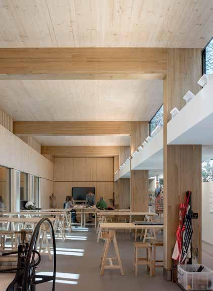
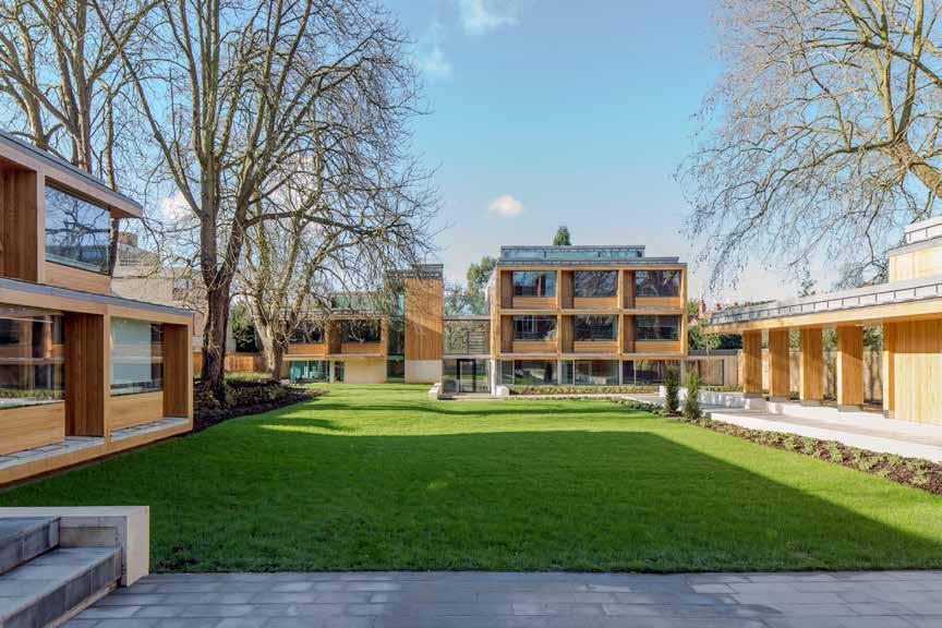
214
© Peter Cook
LOCATION
Oxford, Oxfordshire
HEIGHT / STOREYS
42 ft (12.8 m) / 3 storeys
CONSTRUCTION COST
£4.5 million
ARCHITECT
Hodder + Partners
STRUCTURAL ENGINEER
Thornton Tomasetti
TIMBER ENGINEER
Eurban
TIMBER CONTRACTOR
Eurban
TIMBER MANUFACTURER
Hasslacher
MAIN CONTRACTOR
Benfield and Loxley
TIMBER VOLUME
11,400 ft 3 (323 m 3)
TIMBER ASSEMBLY
12 weeks
OVERALL CONSTRUCTION
66 weeks
Residential (Education)
ST CLARE’S COLLEGE
St Clare’s College
This project comprises five individual buildings woven between existing mature trees, with a restored Grade II listed villa at its head. Linked by walkways the buildings create a quadrangle reminiscent of the traditional Oxford college layout.
The villa is flanked by a new warden’s house, and a single storey timber lined arts studio. Opposite the villa is a pair of linked two and three storey buildings housing student accommodation. The quadrangle is completed to the south by another ‘pavilion’ of single and double study rooms.
All five buildings have a CLT structure and are clad with a rainscreen of vertical oak boards. The use of CLT lent itself to the cellular nature of study rooms which is expressed on the façades. The material language seeks to reinforce the notion of pavilions in a garden.
The naturally-ventilated art studio has an oak glulam portal frame which supports the CLT roof and wall panels. Glazed panels and doors between the glulam columns on the south side are protected from the strong sunlight by doors and an oak-clad CLT canopy cantilevers over the walkway, supported by the glulam columns. Continuing beyond the wall of the studio the canopy and the glulam columns create a cloister-like loggia which defines the north side of the quadrangle.
STRUCTURE TYPE
Pure CLT
EMBODIED CARBON WITHIN TIMBER*
-198 tons (-179 tonnes) CO 2 e 2015
CLT FACT
Proportions of the study rooms suited CLT perfectly
215
First
Plan
Floor
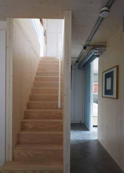

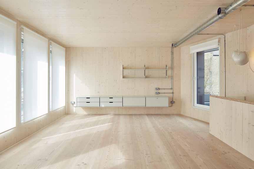
216
© Adrian Wolfson
© Alex Sarginson
© Alex Sarginson
CLT helped towards achieving Passivhaus status
Residential (Private)
LANSDOWNE DRIVE PASSIVHAUS
Bernard Tulkens
The building is located in a conservation area in East London on an infill garden site amidst four storey Victorian terraced houses. Sitting behind a garden wall along the street, the house is half sunken to remain discreet, a suggestion from the local planning department. From the street the house appears as a low, zinc-clad chamfered volume.
Responding to the context, the objective was to create a building with the generic simplicity, flexibility, light and character found in industrial spaces. The main construction components have been left exposed internally. The structural concrete of the lower ground floor roots the building, while the CLT panels which form the living spaces on the upper level sit alongside the conduits and ducts, providing a simple palette of materials and a very direct sense of the construction.
A modern space made using natural materials, with ultra-low energy requirements, the building was awarded Passivhaus status. It is the first certified Passivhaus in the UK to use CLT and woodfibre insulation construction.
217 LOCATION
WITHIN TIMBER*
STRUCTURE TYPE HEIGHT / STOREYS
ARCHITECT STRUCTURAL
TIMBER
TIMBER
TIMBER MANUFACTURER
TIMBER VOLUME TIMBER ASSEMBLY OVERALL CONSTRUCTION Pure CLT N/A
EMBODIED CARBON
CLT FACT
CONSTRUCTION COST
ENGINEER
ENGINEER
CONTRACTOR
MAIN CONTRACTOR
Eurban Eurban Michael Hadi Associates 16 ft (4.9 m) / 2 storeys TECTONICS Architects £350,000 London Borough of Hackney -15 tons (-14 tonnes) CO 2 e 46 weeks 2 days Hasslacher 900 ft 3 (25 m 3)
2015
First Floor Plan

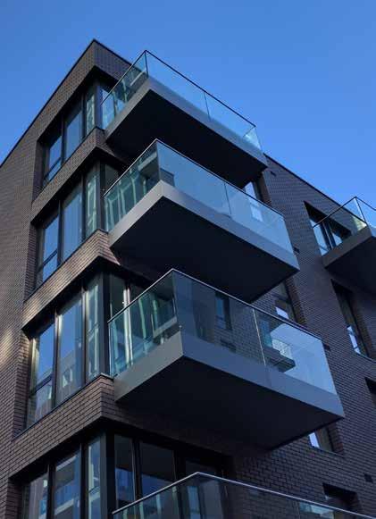
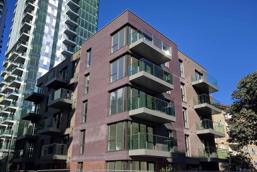
218
© Waugh Thistleton Architects
STRUCTURAL ENGINEER TIMBER ENGINEER TIMBER CONTRACTOR
TIMBER MANUFACTURER
MAIN CONTRACTOR TIMBER VOLUME TIMBER ASSEMBLY OVERALL CONSTRUCTION
DOWN
The Woodberry Down Estate spans a total of 64 acres, next to the New River and West and East Reservoirs, which total 42 acres of open water, in an area of north-east London which is undergoing significant re-development. The process of demolishing 1,980 homes and rebuilding over 5,500 is scheduled across eight phases over a period of 20 years.
As the first CLT building within the estate development, this is the first venture into CLT construction for Berkeley Homes, one of the UK’s largest house builders. The objective was to encourage the wider adoption of CLT construction in both the coming phases of the regeneration, and throughout Berkeley Homes’ development portfolio.
Originally designed to be built using a reinforced concrete frame, the decision to change to a CLT structure came at a relatively late stage. Despite this, the layout of this five-storey building was able to remain largely unchanged with internal steel columns replacing the concrete columns to achieve the large openings for the corner windows. The thinner floor build up reduced the height by 3 inches per storey which in turn reduced the quantity of building materials used. The 19 homes were delivered ahead of schedule and achieved higher than anticipated thermal and air tightness performance.
219 LOCATION
STRUCTURE
HEIGHT
EMBODIED CARBON WITHIN TIMBER* CLT FACT
TYPE
/ STOREYS CONSTRUCTION COST ARCHITECT
Pure
Berkeley
Undisclosed Eurban
Eurban
ft
m) / 5
CO 2 e 39 weeks 5.5 weeks
17,800
3 (503 m 3) 2016 London
Residential
Section
CLT
Homes
Eurban
CLT erected 6.5 weeks quicker than the originally planned concrete frame Waugh Thistleton Architects 51
(15.4
storeys -313 tons (-284 tonnes)
Stora Enso
ft
Borough of Hackney
WOODBERRY
Berkeley Homes
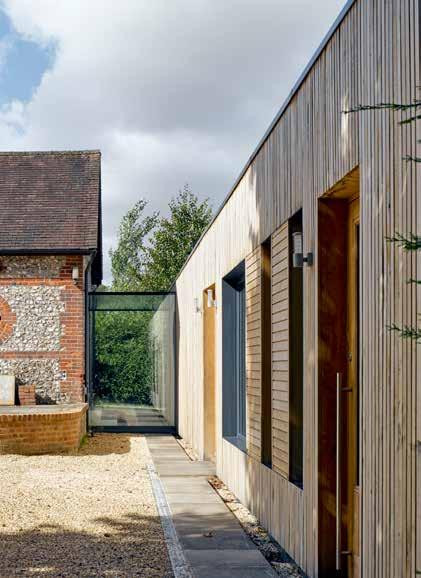
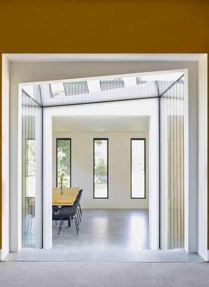
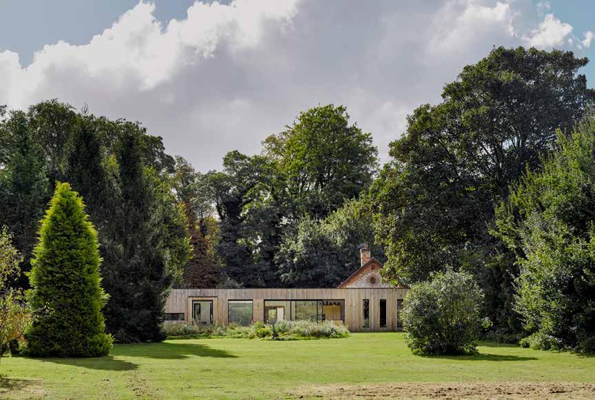
220
© James Morris
2016 Residential (Private)
HURDLE HOUSE
Private Client
LOCATION
Alresford, Hampshire
11 ft (3.5 m) / 1 storeys
CONSTRUCTION COST
£250,000
HEIGHT / STOREYS ARCHITECT
Adam Knibb Architects
STRUCTURAL ENGINEER
Eckersley O’Callaghan
TIMBER ENGINEER
KLH UK
TIMBER CONTRACTOR
KLH UK
TIMBER MANUFACTURER
KLH Massivholz
MAIN CONTRACTOR
Gregory Collins
TIMBER VOLUME
1,100 ft 3 (31 m 3)
TIMBER ASSEMBLY
4 days
OVERALL CONSTRUCTION
20 weeks
Hurdle House is a Grade II listed barn, constructed in the mid eighteenthcentury. The house has a north-south axis with an extensive rear garden and expansive views to the north. The building receives sunlight throughout the day and is overlooked only by the surrounding trees and fields. The contemporary extension aims to provide a social heart to the house harnessing the fantastic views not allowed by the original building.
Set at a 90-degree angle to the original house, a frameless glass space lightly connects the old with the new. Rethinking the movement from public to private areas, the extension uses visual barriers rather than physical blockades to demarcate the spaces that comprise large open plan kitchen, dining area, casual seating and study. Large glass apertures blur the boundaries between the natural surroundings of the property and the interior spaces and the new entrance arrives in the heart of this space, providing direct views into the garden.
Timber was the central component of the project, determining the scale, form and openings and tying the materiality of the building to the expansive landscape that surrounded the existing property. Vertical timber cladding mimics the surrounding trees and provides a contemporary contrast to the existing building.
STRUCTURE TYPE
Pure Timber
EMBODIED CARBON WITHIN TIMBER*
-19 tons (-17 tonnes) CO 2 e
CLT FACT
Timber chosen to tie in with landscape and reduce waste on site
221
Ground Floor Plan
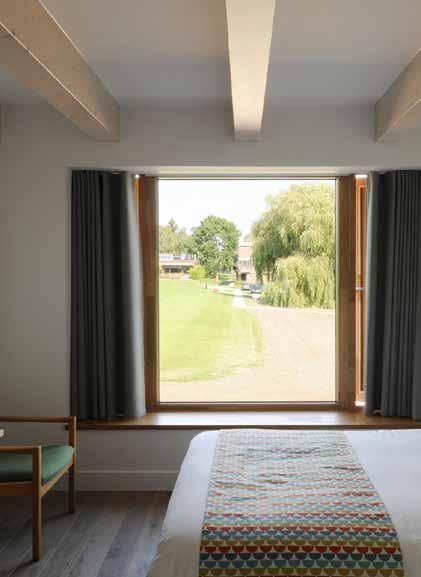
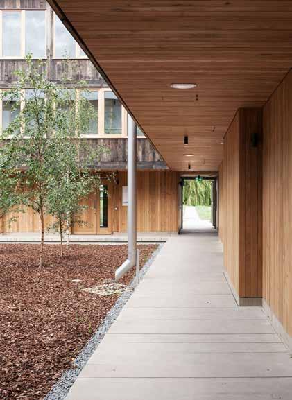
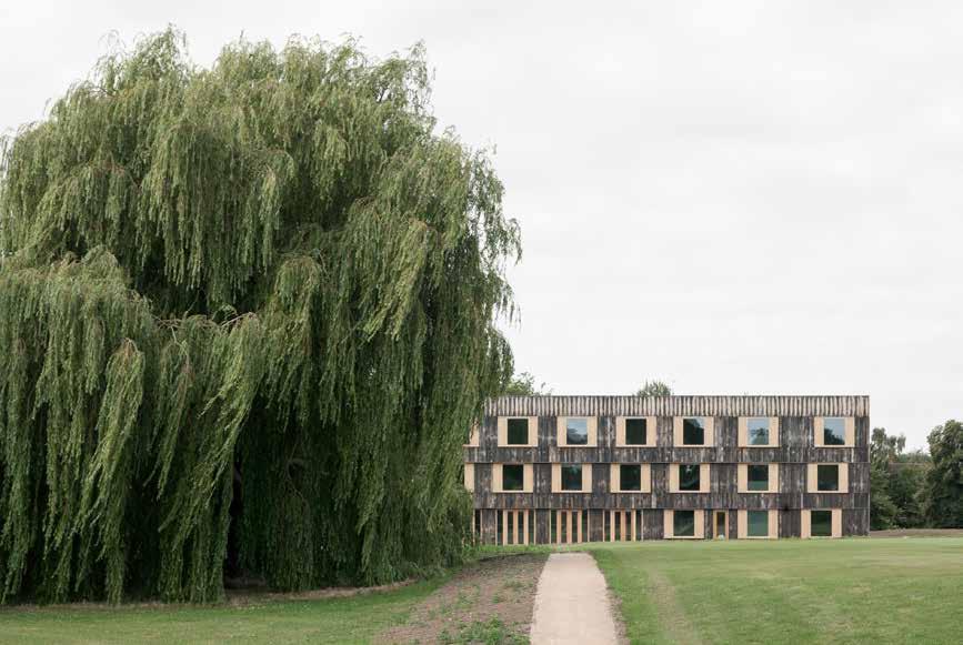
222
© Johan Dehlin
Residential (Education) Churchill College COWAN COURT
Cambridge, Cambridgeshire
HEIGHT / STOREYS
33 ft (10 m) / 3 storeys
CONSTRUCTION COST ARCHITECT
£9.22 million
Cowan Court is a 68-room hall of residence and the first completely new court since the college was founded as a memorial to Sir Winston Churchill in the early 1960s. This new court, adjacent to the existing accommodation courts, turns the Brutalism of the original buildings towards the 21st century bringing sustainability, accessibility, landscape and a new approach to communal and private space to the heart of the design.
STRUCTURAL ENGINEER
Pryce & Myers
TIMBER ENGINEER
TIMBER CONTRACTOR
TIMBER MANUFACTURER
Binderholz / Rubner Holzbau
MAIN CONTRACTOR
Cowan Court responds to the original in a contemporary timber construction. In three overhanging floors, the jettying timber cuts recall the concrete bands across the façades of the existing courts. Each of the façades is curved like the entasis of a classical column, and the square windows of the student rooms spiral up and across.
The structure of the building consists of a glulam post and beam frame with CLT floor panels. Each wing is braced by full height CLT or concrete shear walls, with the concrete walls restricted to the two cores. The glulam beams remain exposed in most areas, giving a rhythm and natural depth to the interior. The materiality forms part of an ambitious environmental strategy; passive ventilation, triple glazing and super insulation reduced the amount of energy consumed in construction and in use. Solar electricity and rainwater collection reduce the energy requirements yet further.
11,100 ft 3 (314 m 3)
TIMBER VOLUME TIMBER ASSEMBLY
OVERALL CONSTRUCTION
6a Architects 77 weeks 14 weeks B & K Structures Engenuiti
STRUCTURE TYPE
EMBODIED CARBON WITHIN TIMBER*
CLT FACT
Engineered timber structure chosen for sustainability credentials
223
LOCATION
Pure
SDC
CO 2 e
Timber
-191 tons (-173 tonnes)
First Floor Plan
2016
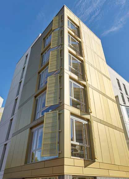
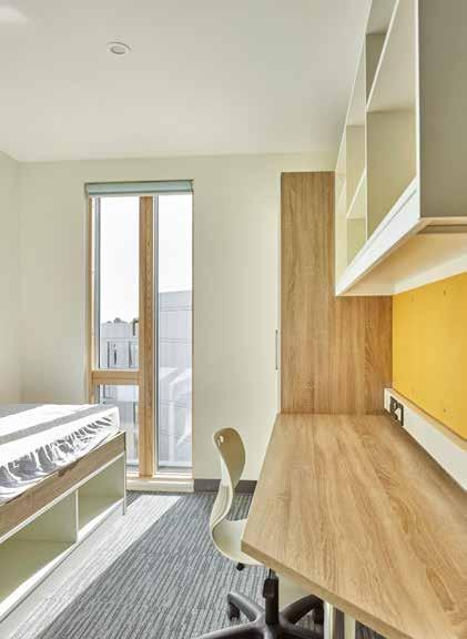
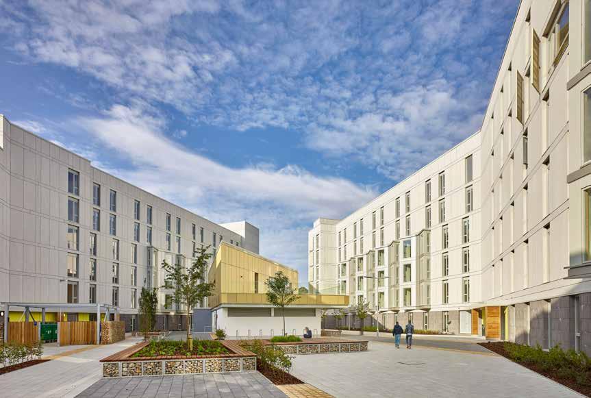
224
© Richard Osbourne
2016
Residential (Education)
UEA BLACKDALE
University of East Anglia
Set over two blocks this new residential quarter for the university provides 514 new student rooms. The design for both student accommodation blocks, named Hickling House and Barton House, takes inspiration from the distinctive shapes of the 1960s Denys Lasdun Teaching Wall.
COST
Norfolk 71 ft (21.7 m) / 5 storeys £27.5 million
ENGINEER
The Blackdale student accommodation is a gateway into the university campus. Blocks are clad with pale grey panels, chosen to complement the concrete structures of the original campus, with gold accent cladding on key views. Angled windows project from the façade to obscure views from outside, adding visual interest and a means to channelling light into the building.
The use of CLT was key in supporting the university’s environmental policies and reduced the embodied carbon of the construction. It also enabled the tight program to be met with students moving in for the autumn semester.
MANUFACTURER
MAIN CONTRACTOR
Architects KLH Massivholz 128,200 ft 3 (3,930 m 3) 17 weeks 62 weeks
VOLUME
OVERALL CONSTRUCTION
CLT R G Carter
STRUCTURE TYPE
-2,242 tons (-2,034 tonnes) CO 2 e
EMBODIED CARBON WITHIN TIMBER* CLT FACT TIMBER ASSEMBLY
Use of CLT was in line with the University’s environmental policy KLH UK TIMBER CONTRACTOR
225 LOCATION
ARCHITECT
TIMBER
HEIGHT / STOREYS
CONSTRUCTION
STRUCTURAL
TIMBER ENGINEER
TIMBER
Pure
Ramboll
LSI
Ramboll Norwich,
First Floor Plan in Context
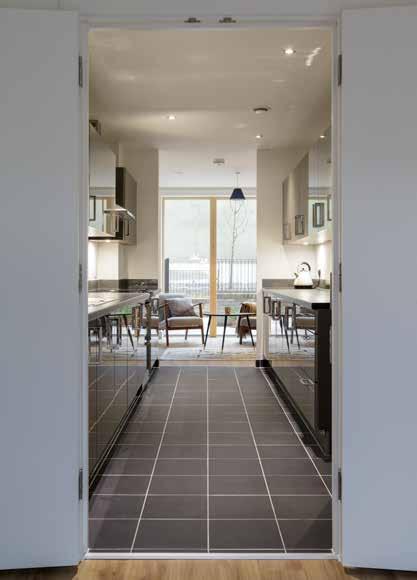


226
© Tim Crocker
CONSTRUCTION COST ARCHITECT
STRUCTURAL ENGINEER
Residential Camden Council BACTON LOW RISE (PHASE 1)
This community-led regeneration project focuses on the transformation of a 1960s estate into a new community of homes for new and existing residents; reconnecting the new neighborhood with the local community.
The 294 unit masterplan achieved planning in March 2013. The first phase started construction in March 2014 and by November 2015 all existing residents had moved into their new homes.
The first phase provided a decant site: a narrow triangle of land next to a high-speed trainline with severe noise and vibration constraints. To counteract this a physical buffer of townhouses and stacked maisonettes was built along the railway. The use of CLT enabled the construction to mitigate the acoustic and vibration impact from the trains, which was very efficient compared to traditional RC frame construction.
CONTRACTOR TIMBER MANUFACTURER MAIN CONTRACTOR
The light weight reduced number of piles and enabled a complex site Stora Enso
Initially concerned that specifying CLT would narrow the field of contractors and reduce the competitive tender, the client’s perception was swiftly overcome by the benefits of using CLT on a tight urban site. The frame was quick to install and was slotted and bolted together with very low levels of noise and dust. Fewer piles were required, resulting in less noise and lowering costs. Reduced deliveries meant that the site could run more efficiently and had less impact on the local community.
EMBODIED CARBON WITHIN TIMBER* CLT FACT STRUCTURE TYPE
227
LOCATION HEIGHT
/ STOREYS
TIMBER
TIMBER ASSEMBLY
Hybrid Rydon -1,077 tons (-977 tonnes) CO 2 e Eurban 90 weeks
TIMBER
VOLUME
OVERALL CONSTRUCTION
Block
60,800
Eurban TIMBER
Roltons £18
57
London
2017
Block A - 8 weeks
B - 10 weeks
ft 3 (1,72 m 3)
ENGINEER
million Karakusevic Carson Architects
ft (17.5 m) / 5 storeys
Borough of Camden
Townhouse Sectional Axonometric
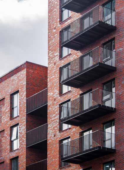

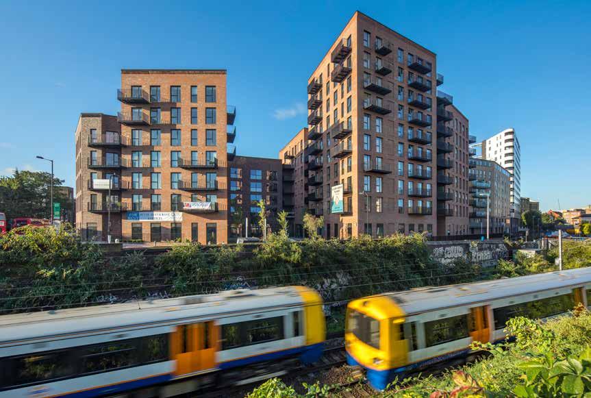
228
© Daniel Shearling
© Daniel Shearling © Waugh Thistleton
STRUCTURAL ENGINEER TIMBER ENGINEER TIMBER CONTRACTOR
TIMBER MANUFACTURER
Residential
DALSTON WORKS
Regal London
Dalston Works is the world’s largest CLT building, delivering 121 new affordable and private (for rent) homes alongside 38,000ft 2 of commercial space.
Designed as a village within a city, the plan is modulated to break down the large site into discernible volumes, orientated to maximize daylight to courtyards and living spaces. A public courtyard activates the existing streetscape, while a second courtyard offers a private, secluded space for residents. The building’s intricate brickwork references the surrounding Victorian and Edwardian housing and the detailing of local warehouses, providing a contemporary addition to the local streetscape.
Conceived of and built in solid timber, Dalston Works showcases how CLT can help deliver high-quality, high-density housing without compromising the environment. Constrained by the future Crossrail 2 train line that runs under the site, the CLT weighs a fifth of a comparable concrete structure. This reduced weight combined with the minimal raft foundation enabled the creation of 35 additional homes than would have been otherwise possible in concrete frame.
Rising to 10 storeys at its highest, the CLT structure uses the equivalent of 2,325 trees - around three trees per person living or working in the building.
229 LOCATION
EMBODIED CARBON WITHIN TIMBER* CLT FACT STRUCTURE TYPE HEIGHT / STOREYS
CONSTRUCTION COST ARCHITECT
MAIN CONTRACTOR TIMBER VOLUME TIMBER ASSEMBLY
CLT Regal
OVERALL CONSTRUCTION Pure
Homes
& K
CO 2 e
ft 3 (4,649 m 3)
Ramboll PJCE Undisclosed
ft (33.8 m) / 10
2017
Delivers 35 more homes than would be possible with a concrete frame B
Structures 130 weeks 52 weeks -2,878 tons (-2,611 tonnes)
164,200
Binderholz
Waugh Thistleton Architects 111
storeys
London Borough of Hackney
Sectional Axonometric of CLT
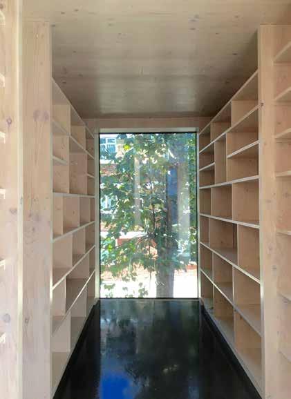

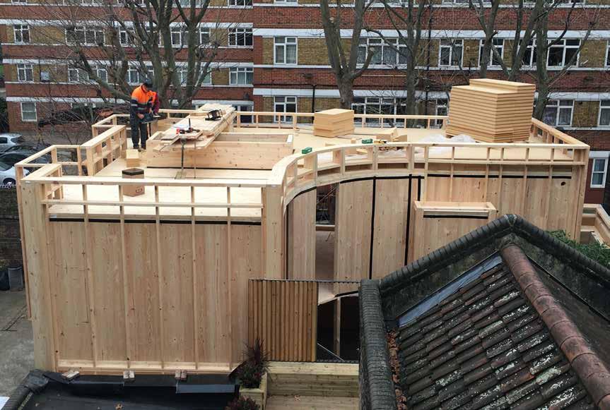
230
© Mosley and Mann
2017 Residential (Private)
CARMARTHEN HOUSE
Amanda & Robert Mosley
London Borough of Southwark
HEIGHT / STOREYS
21 ft (6.5 m) / 2 storeys
Located at the boundary of the Bermondsey Street Conservation Area, the density was key to the decision to design a “flat pack” house which could be craned and assembled in minimal time.
£310,000
CONSTRUCTION COST ARCHITECT
Mosley and Mann
STRUCTURAL ENGINEER
Built Engineers / Egoin
TIMBER ENGINEER
Egoin
TIMBER CONTRACTOR
TIMBER MANUFACTURER
Egoin
Prior to this project in 2006, at a time when CLT was very much in its infancy in the UK, the practice had built two award-winning solid timber buildings adjacent to the site. The panels for these two schemes were not CLT but more akin to exceptionally deep glulam beams. At the time the architects worked to overcome local resident’s and building control’s concerns about mass timber construction.
Permission was granted for the new project and access through the neighboring private estate agreed on the basis that a quick and quiet build time could be ensured; the success of the previous schemes acting as precedent to this.
The CLT structure of Carmarthen House took just 2 days to secure in place. All exposed internally, the timber provides a natural breathable environment with a beautiful finish. The selection of CLT for the structure enabled the interesting design features of the house to be executed easily.
2,800 ft 3 (80 m 3)
2 days
56 weeks
STRUCTURE TYPE
EMBODIED CARBON WITHIN TIMBER*
CLT FACT
231
LOCATION
Pure CLT Build-Met
MAIN CONTRACTOR TIMBER VOLUME TIMBER ASSEMBLY OVERALL CONSTRUCTION
-49 tons
CO 2 e First Floor Plan
CLT chosen due to access constraints Egoin
(-45 tonnes)
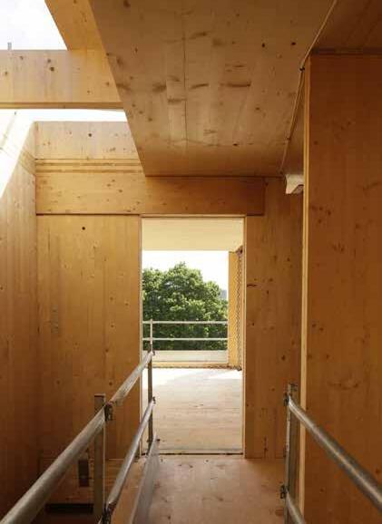
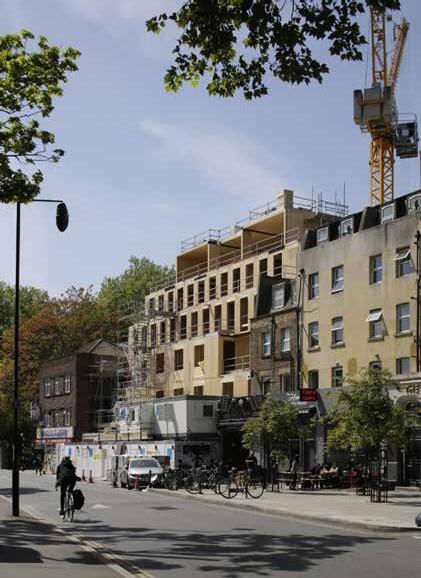
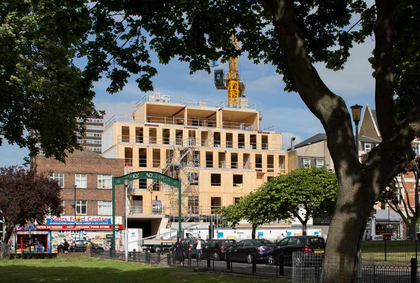
232
© Lewis Kahn
2018 Residential (Cinema)
PITFIELD STREET
Garfwish Ltd
LOCATION
London Borough of Hackney
HEIGHT / STOREYS
61 ft (18.5 m) / 6 storeys
CONSTRUCTION COST
£9.4 million
ARCHITECT
Waugh Thistleton Architects
STRUCTURAL ENGINEER
Elliott Wood
TIMBER ENGINEER
Pryce & Myers./ KLH UK
TIMBER CONTRACTOR
KLH UK
TIMBER MANUFACTURER
KLH Massivholz
MAIN CONTRACTOR
Simply Construct
TIMBER VOLUME
18,800 ft 3 (533 m 3)
TIMBER ASSEMBLY
12 weeks
OVERALL CONSTRUCTION
96 weeks
Pitfield Cinema combines the restoration of a derelict, turn of the 20th century neighborhood cinema with the development of new commercial and residential accommodation, comprising 18 luxury apartments.
The design consists of two distinct elements, a solid concrete basement and ground level, which accommodates the three-screen cinema, and a CLT element from first floor podium level to form the apartments. The timber element is stepped back from the street to provide balconies behind the historic façade. A single penthouse occupies the top floor enjoying panoramic urban views, with open plan living achieved through the use of wide spanning CLT members.
The challenge of building a cinema directly below living accommodation was achieved using ‘box within-a-box’ construction. The cinema is effectively isolated from the remainder of the structure. In this way, the CLT structure above is fixed onto a slab which is entirely independent of the cinema ceilings, and load paths are transferred to the foundations independently.
Constraints on the permissible height of the building were met through the use of CLT without compromising the internal room heights. The floor buildup, including underfloor heating, service voids and acoustic separation was under 16 inches thick, which is not achievable with other forms of construction.
STRUCTURE TYPE
Hybrid
EMBODIED CARBON WITHIN TIMBER*
-332 tons (-301 tonnes) CO 2 e
CLT FACT
Using CLT allowed an extra storey due to savings in floor to floor heights
233
Section

COMMERCIAL
The commercial sector is currently an emerging market for CLT, its relative infancy indicated by the far fewer number of commercial projects included within this study. The use of CLT by companies such as Sky and more recently Google, for their new European headquarters currently starting on site in Kings Cross, illustrates the acceptance of CLT by influential leaders of the sector. It is expected that the breakthrough with these companies will lead to accelerated uptake within this sector.
Most commercial schemes require large open uninterrupted spaces that are flexible and adaptable. Hybrid structures, where CLT is used in combination with glulam, LVL or steel beams to create wider spans without excessively thick panels of CLT, are therefore common in commercial buildings.
In addition to these conventionally planned open offices, the case studies within this sector include several examples of renovations to existing offices where a rooftop extension in CLT has been possible. The potential for CLT to be used on top of existing schemes, often without the need for additional reinforcements to the existing foundations, can facilitate an increase in net internall area.
At least part of the timber structure is exposed in each of the commercial buildings included, as such it is clear to see that the aesthetic and environmental benefits of CLT are highly valued within this sector. The reasons for exposing the timber in these schemes are varied but include the first monolithic CLT project built in the UK, where the primary driver for exposing the CLT was its ability to regulate the internal humidity levels, essential for preservation of the artefacts stored within.
235
Image: Sky Believe in Better Building, Arup Associates © Simon Kennedy

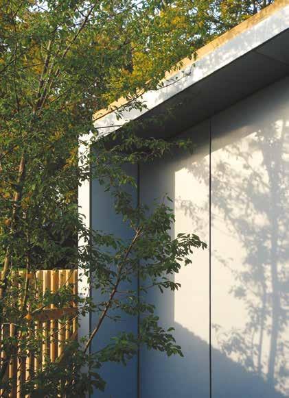

236
© David Grindley Architects
Keynes, Buckinghamshire
In the redesign and extension of their existing studio, David Grindley took the opportunity to place an emphasis on the use of sustainable materials and prefabrication. The building is constructed almost entirely of CLT which provides not only the structure but also the aesthetic language of the building.
Tapsell Wade and Partners
MANUFACTURER TIMBER CONTRACTOR TIMBER ENGINEER STRUCTURAL ENGINEER
CONTRACTOR
The new studio is a linear, single storey, open-plan space with north facing, clerestory windows that bring natural light into the building. The interior is an open plan space divided into four distinct zones by solid timber panels cut to half the width of the room. The timber has been left exposed internally, diffusing the light from the north facing clerestory windows to create a serene and healthy working environment.
The façade is articulated by vertical timber boarding which continues onto the adjacent side of the pitched roof, and acts to obscure the horizontality of the building within its wooded context. This side of the building faces onto the neighboring green, its materiality sympathetic to and cohesive with the landscape. The lightweight timber lessens the impact on the roots of the mature trees which surround the site.
ASSEMBLY
237 LOCATION
WITHIN TIMBER* CLT FACT STRUCTURE
TIMBER
ARCHITECT
COST HEIGHT / STOREYS N/A Pure CLT 26 weeks Lightweight CLT reduces impact on the roots of surrounding trees 2 days KLH UK -7 tons (-7 tonnes) CO 2 e 11 ft (3.5 m) / 1 storey 500 ft 3 (14 m 3) TIMBER VOLUME KLH Massivholz
KLH UK David
£75,000 Milton
EMBODIED CARBON
TYPE OVERALL CONSTRUCTION
MAIN
TIMBER
CONSTRUCTION
Grindley Architects
2006 Axonometric Commercial
David Grindley Architects THE OFFICE


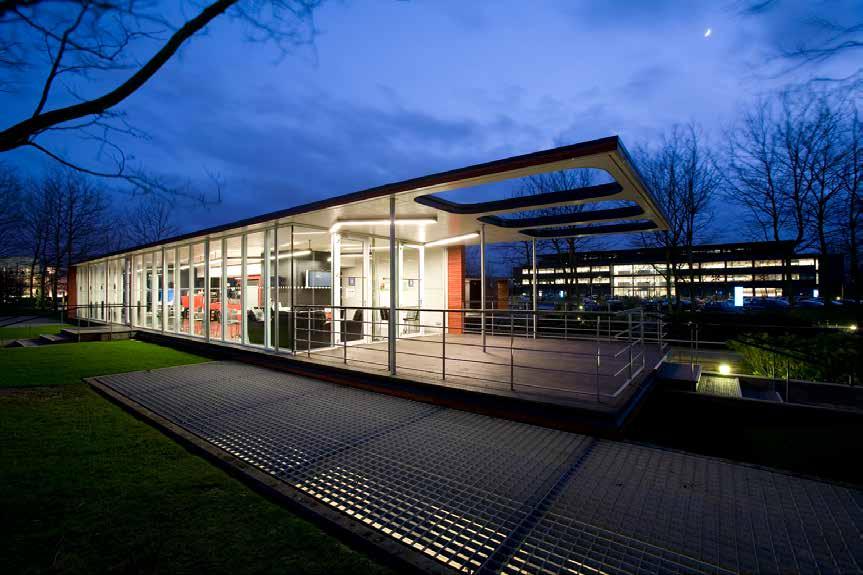
238
© David Grandorge
2006
Commercial
BEDFONT LAKES PAVILION
Scottish Widows Investment Partnership
LOCATION
Feltham, Middlesex
14 ft (4.3 m) / 1 storey
CONSTRUCTION COST
£400,000
HEIGHT / STOREYS ARCHITECT
Archer Architects
STRUCTURAL ENGINEER
Akera Engineers
TIMBER ENGINEER
Akera Engineers
TIMBER CONTRACTOR
KLH UK
TIMBER MANUFACTURER
The Bedfont Lakes Pavilion was designed as a new social hub, café and management centre for the occupants of the neighboring buildings. The plot, located above an active car park and amidst occupied offices, required a solution which would have minimal impact on the site and the surrounding area.
A prefabricated building was the obvious answer. The simple single storey rectangular space was constructed using cross laminated timber. The complete panelized system was delivered to site pre-finished and erected within a short five day period. Being largely self-supporting, an essential feature for construction above the existing car park, the need for additional structure was minimized with the whole build taking only 12 weeks to complete.
One of the first CLT projects in the UK, this building demonstrated some of the benefits of CLT that are now considered common knowledge, with cost modelling of the project demonstrating that the unit cost of this form of construction was lower than conventional construction.
MAIN CONTRACTOR
Bryan and Langley
TIMBER VOLUME
3,500 ft 3 (100 m 3)
TIMBER ASSEMBLY
1 week
12 weeks
STRUCTURE TYPE
OVERALL CONSTRUCTION Hybrid
EMBODIED CARBON WITHIN TIMBER*
KLH Massivholz -62 tons (-57 tonnes) CO 2 e
CLT FACT
The use of CLT enabled construction on top of an existing car park
239
Exploded Axonometric
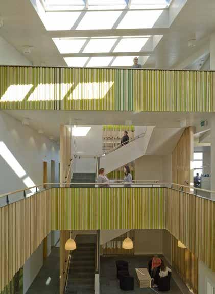
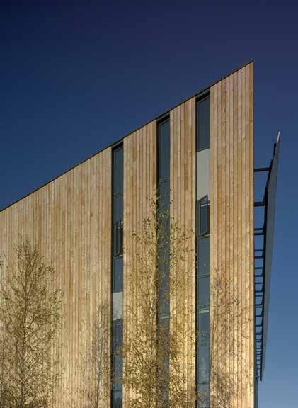
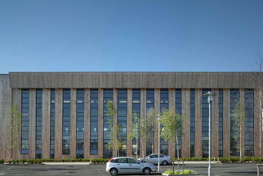
240
© Peter Cook / VIEW
LOCATION
Grantham, Lincolnshire
HEIGHT / STOREYS
49 ft (15 m) / 3 storeys
CONSTRUCTION COST
£5 million
ARCHITECT
Feilden Clegg Bradley Studios
STRUCTURAL ENGINEER
Atelier One
TIMBER ENGINEER
Atelier One
TIMBER CONTRACTOR
B & K Structures
TIMBER MANUFACTURER
KLH Massivholz
MAIN CONTRACTOR
Bowmer & Kirkland
TIMBER VOLUME
24,100 ft 3 (682 m 3)
TIMBER ASSEMBLY
12 weeks
OVERALL CONSTRUCTION
56 weeks
Commercial
WOODLAND TRUST HEADQUARTERS
The Woodland Trust
Located on a greenfield site, the brief for the new headquarters was to create a woodland experience from the moment people arrive. Staff and visitors are welcomed through a central garden planted with birch trees, and the façade of the building is clad in larch giving a feeling of being amongst trees.
The building ascends in a spiral, creating a dynamic transition between the landscape and the building. The internal spaces are grouped around a top-lit atrium, which acts as both a reception area and a congregation space for the staff. Three storey vertical windows on the north and south elevations flood the interior with natural light and ventilation. CLT provides the structure, creating an incredibly light, breathable building that reflects the ethos of the charity through its very materiality.
To regulate the temperature of the building a series of 81 ‘concrete radiators’ – concrete boxes fixed to the CLT soffits - work structurally in composite with the timber and were designed to provide sufficient thermal mass, absorbing and re-emitting heat from the offices through the night to create a naturally regulated comfortable internal temperature.
As a charity the Woodland Trust was keen to demonstrate value for money. A thorough cost comparison demonstrated that CLT offered a frugal solution whilst also meeting sustainability objectives.
STRUCTURE TYPE
Hybrid
EMBODIED CARBON WITHIN TIMBER*
Combination of CLT with ‘concrete radiators’ optimized thermal mass -424 tons (-385 tonnes) CO 2 e
CLT FACT
241
2010
Section
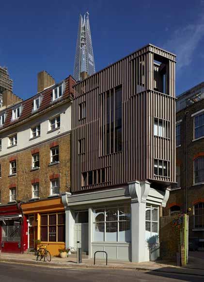
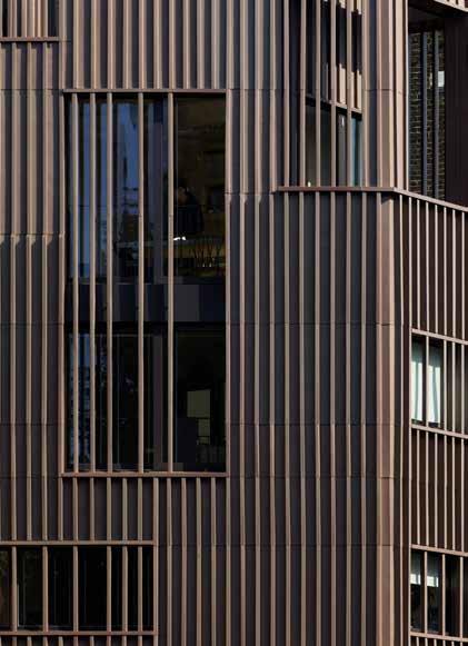
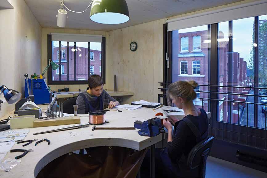
242
© Dennis Gilbert
LOCATION
London Borough of Southwark
HEIGHT / STOREYS
48 ft (14.5 m) / 5 storeys
CONSTRUCTION COST
£439,000
ARCHITECT
DSDHA
STRUCTURAL ENGINEER
Structure Workshop
TIMBER ENGINEER
Structure Workshop
TIMBER CONTRACTOR
KLH UK
TIMBER MANUFACTURER
KLH Massivholz
Commercial
ALEX MONROE STUDIO
Alex Monroe
The building provides workshop and studio space, alongside a boutique store, a meeting space and a roof terrace. Large sliding doors in the workshop allow for generous engagement with the street, providing a place to extend one’s view as a counterpoint to the intimate work on the jewellery bench, whilst the third floor balcony extends the outdoor into the interior. Activities on each floor are connected by a spacious staircase that doubles as an exhibition space.
Situated within a conservation area, the modern zinc façade compliments the quality of the surrounding context. Site based fabrication ensured refined details throughout the key junctions of the façades, resulting in a high quality building that mirrors the fine craftsmanship within. The façade ‘fins’ shift selectively in front of windows to animate the elevation and control views in and out of the building, introducing dynamism in the street. The horizontal details subtly relate to the context of the neighboring terraces.
The building consists of a CLT timber panel structure that sits on a combination of steel beams and masonry load-bearing walls at the ground
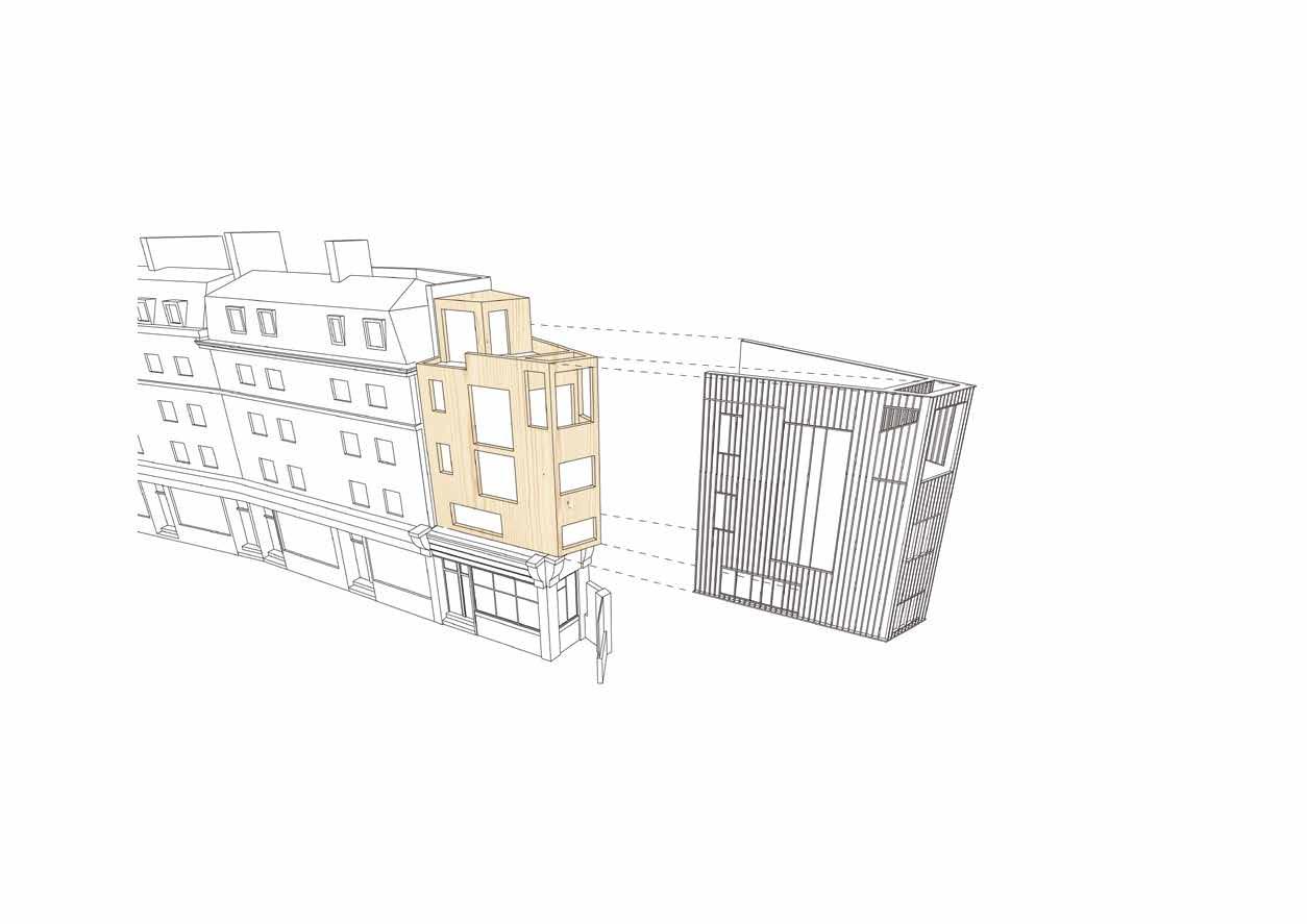
2012

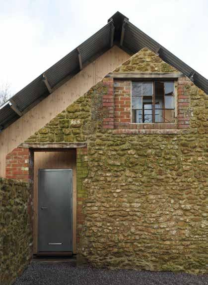
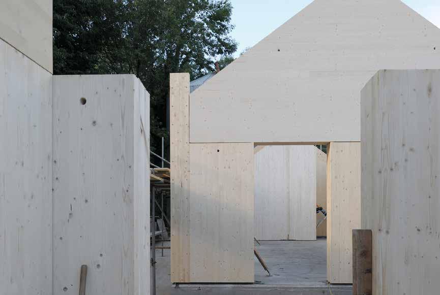
244
© David Grandorge
2014
Commercial Drawing Matter ARCHITECTURE ARCHIVE
LOCATION
Somerset
15 ft (4.5 m )/ 1 storeys
CONSTRUCTION COST
£250,000
HEIGHT / STOREYS ARCHITECT
Hugh Strange Architects
STRUCTURAL ENGINEER
Price & Myers
TIMBER ENGINEER
Eurban
TIMBER CONTRACTOR
Eurban
TIMBER MANUFACTURER
Stora Enso
MAIN CONTRACTOR
N/A
TIMBER VOLUME
5,500 ft 3 (155 m 3)
TIMBER ASSEMBLY
3 weeks
OVERALL CONSTRUCTION
39 weeks
This building integrates a monolithic CLT structure within an existing rural setting. The dilapidated walls and roof of an old stone and brick barn have been removed and the remaining walls carefully stabilized and repaired. Within these walls two timber structures have been inserted with a single new roof over-sailing the whole composition and providing a covered entrance. The two new timber buildings are identical in their volumes but subtly differentiated in their fenestration and fit-out. The south building provides a drawing archive and display space and is predominantly top lit by a generous roof light.
The CLT panels, ranging in thickness from 12 - 17 inches simultaneously provide structure, insulation and thermal mass, creating a stable internal environment in terms of both temperature and relative humidity. Taking advantage of the natural properties of timber, this simple but bold solution provides the ideal climate for storing the client’s collection of historic and contemporary drawings, models and books.
As the first monolithic CLT building in the UK, the Architecture Archive has been an important step in illustrating the true potential of exposed mass timber construction. The building is currently being environmentally monitored to record its performance, serving as a useful prototype for this unique style of construction.
STRUCTURE TYPE
Pure CLT
EMBODIED CARBON WITHIN TIMBER*
-94 tons (-86 tonnes) CO 2 e
CLT FACT
First monolithic CLT building in the UK
245
Section

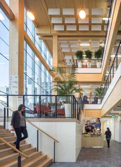
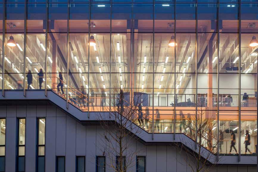
246
© Simon Kennedy / Arup Associates
2014
Commercial Sky UK SKY BELIEVE IN BETTER BUILDING
LOCATION
London Borough of Hounslow
HEIGHT / STOREYS
69 ft (21 m) / 4 storeys
CONSTRUCTION COST
£15 million
ARCHITECT
Arup Associates
STRUCTURAL ENGINEER
Arup
TIMBER ENGINEER
Arup
TIMBER CONTRACTOR
B & K Structures
TIMBER MANUFACTURER
Binderholz / Rubner / KLH Massivholz
MAIN CONTRACTOR
Mace
TIMBER VOLUME
68,300 ft 3 (1,934 m 3)
TIMBER ASSEMBLY
11 weeks
OVERALL CONSTRUCTION
43 weeks
Conceived as a home for Sky’s outreach and academy training programs, the building is intended to be used mainly by visitors. As such the layout is intuitive with a staircase, suspended along the entire side elevation, unifying the four storeys. Designed to be reconfigurable over the long term with no fixed uses, partitions slide and unfold to interconnect a shifting landscape of rooms and spaces.
To provide an open-plan floor plate, structural walls are limited to the stair cores, lifts and divisions between plant and public spaces. Stability is provided by the diaphragm action of the CLT floor plates transferring horizontal forces to the cores. Within the cores, the CLT walls work compositely with the glulam columns to form cantilevered ‘I-beams’ that transfer the stability forces to the ground. The resulting push-pull is transferred to the foundations by the columns, and shear forces resisted by the connection of the walls to the concrete ground floor slab.
The specification of a natural wood structure was key as the first building in the UK to be designed in accordance with emerging Wellness Certification. A fabric first, mixed mode energy strategy, PV’s and site wide CCHP ensured a sustainable approach to occupation as well as construction. This project demonstrates that off-site prefabrication and timber construction can achieve a unique workplace in half the normal time-frame.
STRUCTURE TYPE
Pure Timber
EMBODIED CARBON WITHIN TIMBER*
-1,165 tons (-1,057 tonnes) CO 2 e
CLT FACT
First multi-storey timber commercial office in the UK
247
Section
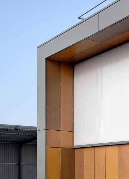
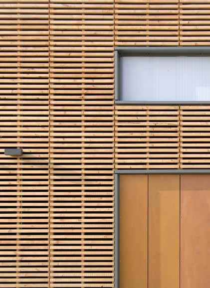

248
© Paul Younger
2015 Commercial CROSSLAM
LOCATION
Hereford, Herefordshire
WORKSHOPS
20 ft (6 m) / 1 storeys
CONSTRUCTION COST
£800,000
HEIGHT / STOREYS ARCHITECT
Hewitt Studios
STRUCTURAL ENGINEER
Integral Engineering Design
TIMBER ENGINEER
Integral Engineering Design
TIMBER CONTRACTOR
KLH UK
TIMBER MANUFACTURER
KLH Massivholz
MAIN CONTRACTOR
C J Bayliss
TIMBER VOLUME
5,300 ft 3 (150 m 3)
TIMBER ASSEMBLY
4 days
OVERALL CONSTRUCTION
26 weeks
STRUCTURE TYPE
Pure CLT
EMBODIED CARBON WITHIN TIMBER*
-95 tons (-86 tonnes) CO 2 e
CLT FACT
Designed to utilize a single thickness of CLT panel throughout
The project was envisaged as a model of how to build a ‘b-class’ building in a sustainable, innovative and flexible way. The College had a number of existing asbestos clad workshops no longer suitable for teaching purposes. The challenge was to demolish an existing workshop and construct a replacement whilst educational activities continued uninterrupted.
Designed to be as efficient as possible the whole building was cut from a single CLT panel type in one operation - a true flat-pack fabrication. Effectively exploiting the omni-directional loading capability of CLT all beams, columns, walls and roof were fabricated from the 8 inch board.
The square-cut sections were fixed together using simple connection details, and services are surface fixed and modular in format to allow for future reconfiguration, if required, as the curriculum evolves. The building is effectively self-finished with no lining or applied finishes.
Externally the building is clad in western red cedar forested from the college’s 150 acres of woodland and cut to size on site by college contractors. Variegated panels of FSC-certified marine plywood soften the building at low-level, whilst extensive use of polycarbonate glazing at high-level allows light deep into the pale timber interior.
Herefordshire and Ludlow College Section
249
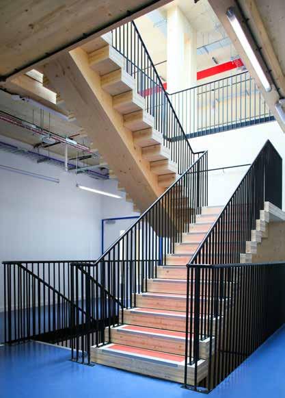
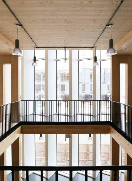

250
© Paul Carstairs / Arup
© Alex de Rijke / dRMM
© Alex de Rijke / dRMM
48 ft (14.5 m) / 3 storeys London Borough of Hounslow
CONSTRUCTION COST
£7 million
ARCHITECT
STRUCTURAL ENGINEER
TIMBER ENGINEER
TIMBER CONTRACTOR
TIMBER MANUFACTURER
Rubner Holzbau / Binderholz
MAIN CONTRACTOR
TIMBER ASSEMBLY TIMBER VOLUME
OVERALL CONSTRUCTION
Sports & Leisure (Commercial)
Sky UK SKY HEALTH AND FITNESS CENTRE
Embodying corporate sustainability policies, this new health and fitness centre on the Sky campus was built using a unique structural arrangement of glulam bifurcated timber columns and glulam beams. The result is close to a flat-slab construction, with CLT perimeter walls, cores and floors.
Developed especially for the project, reinforced glue-laminated ‘superbeams’ span from the front-to-back of the building in a shallow profile. These superbeams utilize flatwise orientations of the timber grain and steel reinforcement to efficiently reduce the depth of the timber beam and overall height of the building compared to traditional glulam beam arrangements. The superbeams are supported by glulam columns that are bifurcated into two vertical elements to provide stiffness and temporary support to the wide beams. CLT floor plates span between the beams to complete the structural system. It is the first engineered timber gymnasium in the UK.
Internally, the gym spaces are connected through a stacked timber stair that links the three floors, void spaces providing visual connection and allowing daylight deep into the plan. A limited material palette was developed of natural, durable materials, while all of the structural timber was left exposed to add a richness of natural texture. The timber structure links this new fitness centre to the adjacent Believe in Better offices finished the previous year.
STRUCTURE TYPE
EMBODIED CARBON WITHIN TIMBER*
CLT FACT
251 LOCATION
Timber Mace
& K
HEIGHT / STOREYS Pure
B
Structures
CO 2 e
2.5 week shorter program than a steel alternative 2015 20 weeks 4.5 weeks -386 tons (-350 tonnes)
22,400 ft 3 (634 m 3)
Arup
B & K Structures
dRMM
First Floor Plan
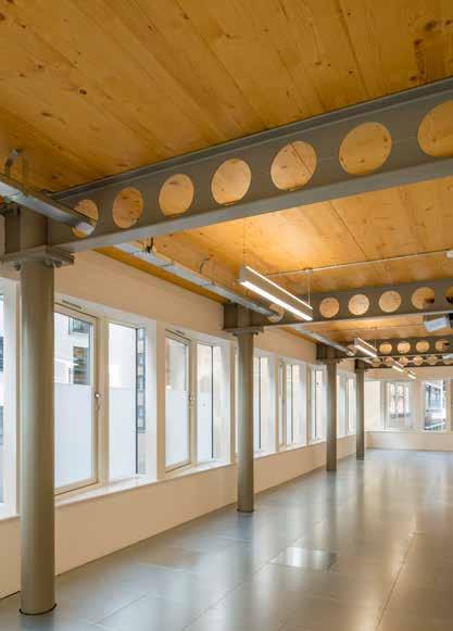
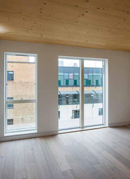

252
© Ben Clarkson
LOCATION
London Borough of Hackney
HEIGHT / STOREYS
66 ft (20 m) / 6 storeys
CONSTRUCTION COST
£4.1 million
ARCHITECT
Waugh Thistleton Architects
STRUCTURAL ENGINEER
Richard Jackson Engineering
TIMBER ENGINEER
B & K Structures / Engenuiti
TIMBER CONTRACTOR
B & K Structures
TIMBER MANUFACTURER
Binderholz
MAIN CONTRACTOR
Gold Section Homes
TIMBER VOLUME
21,600 ft 3 (611 m 3)
TIMBER ASSEMBLY
13 weeks
OVERALL CONSTRUCTION
65 weeks
Commercial / Residential CURTAIN PLACE
Gold Section Homes
Curtain Place is a mixed-use six storey building, plus basement, accessed from a small yard in the heart of Shoreditch, London. The first three storeys are clad in dark brickwork and zinc, and house offices which project into a planted courtyard. Stepped back in line with neighboring buildings are three further residential floors, demarcated with white brick.
The building has a concrete basement, with a hybrid CLT and steel structure from ground floor upwards. All floor slabs, roof slabs, stairs, core walls and external walls are CLT, with cellform beams and columns in steel to facilitate the open-plan office spaces. The timber and services are exposed throughout the office spaces giving a contemporary, stripped-down feel, while sawtooth glazing maximizes views back onto Curtain Road.
The flats are almost entirely formed from CLT, including party walls and partitions. CLT soffits are also exposed in the top floor flats where acoustic requirements were less onerous, bringing warmth to the interior of these inner-city apartments.
Chosen primarily to overcome planning restrictions on building heights, and to assist with access to this backland site, the speed of erection of the CLT was a pleasant surprise for the contractor-developer client. Once the roof membranes and windows were installed, a watertight building was achieved allowing both internal and external works to continue in tandem.
STRUCTURE TYPE
Hybrid
EMBODIED CARBON WITHIN TIMBER*
-372 tons (-338 tonnes) CO 2 e
CLT FACT
CLT interiors drove higher than average sales values
253
2015
Section
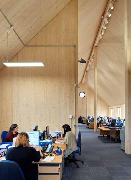
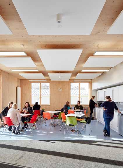
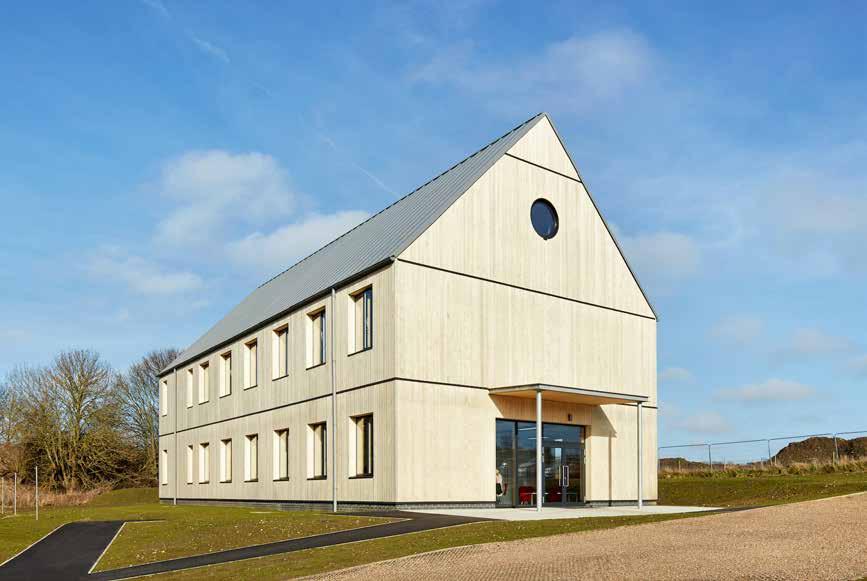
254
© Alan Williams Photography
Commercial Christies Care CHRISTIES CARE OFFICE BUILDING
LOCATION
Saxmundham, Suffolk
43 ft (13 m) / 2 storeys
CONSTRUCTION COST
£1.1 million
HEIGHT / STOREYS ARCHITECT
Nicholas Hare Architects
STRUCTURAL ENGINEER
Integral Engineering Design (IED)
TIMBER ENGINEER
Integral Engineering Design (IED)
TIMBER CONTRACTOR
Eurban
TIMBER MANUFACTURER
Stora Enso
MAIN CONTRACTOR
SEH French
TIMBER VOLUME
7,800 ft 3 (220 m 3)
TIMBER ASSEMBLY
3 weeks
OVERALL CONSTRUCTION
40 weeks
Christies Care is a major employer in the local area. Their new headquarters provides space for around 60 staff. Standing on a sloping site at the edge of town, the building form and external materials were selected to be sympathetic to their context.
The building is a simple two-storey box with a pitched roof running along a north-south axis allowing the primary office windows to face east or west. The ground floor consists of cellular offices and a café, whilst the first floor consists of a single open plan office which extends into the roof space.
The design of the office targeted sustainability both through its material selection and by following Passivhaus principles in its approach to energy efficiency. Chosen for its low embodied energy, speed of construction and appearance within the finished building, the entire superstructure is made of CLT supported on a slender frame of glulam beams and glulam columns.
While the CLT is exposed throughout, basic industrial quality was chosen. The surface was given a dilute white spray, to prevent the timber darkening over time.
The external cladding is of vertical Accoya tongue-and-groove strips. Deliberately left untreated, it will grey over time, in a reference to the traditional local timber barns.
STRUCTURE TYPE
Pure Timber
EMBODIED CARBON WITHIN TIMBER*
-136 tons (-123 tonnes) CO 2 e
CLT FACT
White wash used to reduce effect of the exposed CLT darkening
255
Section
2016
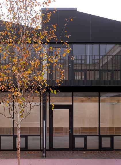
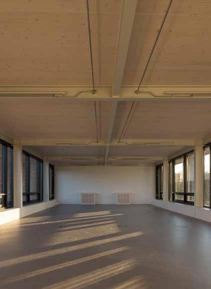
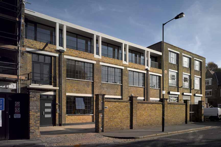
256
© Nick Kane
© Henley Halebrown Architects
© Henley Halebrown Architects
Commercial DE BEAUVOIR
Benyon Estates
CONSTRUCTION COST
ARCHITECT
STRUCTURAL ENGINEER
TIMBER ENGINEER
TIMBER CONTRACTOR
TIMBER MANUFACTURER
MAIN CONTRACTOR
TIMBER VOLUME
TIMBER ASSEMBLY
OVERALL CONSTRUCTION
90-100 De Beauvoir Road consists of 6 Victorian warehouses used primarily as commercial space. They offer well proportioned spaces which have a strong character derived from their simple industrial past. The top floors have high levels of natural light achieved using skylights and generous ceiling heights. The extensions retain these attributes whilst adding their own distinct character.
The roof extension is conceived as a series of identical 320ft 2 units each of which can be linked to the next to create larger spaces. Asymmetric pitched roofs rising to meet roof lights create a gently undulating skyline.
At number 92 and 98 a precast white concrete façade reflects the existing concrete lintels, and the rhythm of the new columns matches that of the brick piers below. At 94 the glass roof and outbuildings were removed to create a central external courtyard. Restoring the ground floor openings on the courtyard side to both the front and back buildings brings light into the ground floor and activity into the courtyard.
The use of CLT throughout the extension allowed for economical construction. Primary elements could be easily manoeuvred into place on the tight site. Manufactured off-site, the precision allowed the extension to accurately interface with the existing structure and building fabric.
STRUCTURE TYPE
HEIGHT / STOREYS Hybrid Sullivan Brothers Construction London Borough of Hackney
EMBODIED CARBON WITHIN TIMBER*
CLT FACT
Using
allowed for easy installation on a tight constrained site
257
LOCATION
39
2
Section
CLT
Eurban Eurban MMP Design 48 ft (14.5 m) / 4 storeys Henley Halebrown Architects £5 million -29 tons (-26 tonnes) CO 2 e
weeks
weeks 1,700 ft 3 (49 m 3) Hasslacher 2017
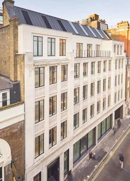
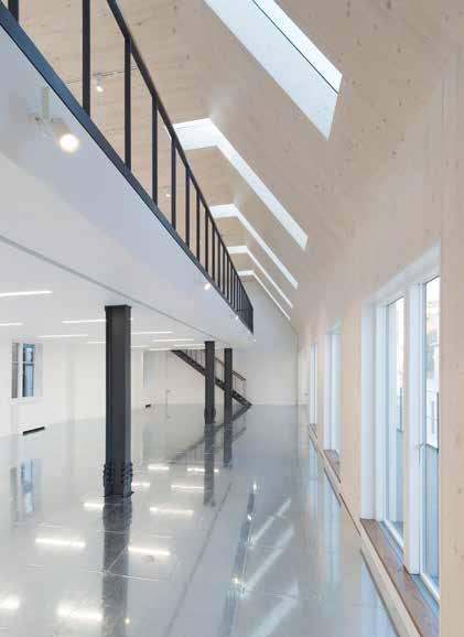

258
© Richard Leeny
© Image Works © Richard Leeny
2017 Commercial
LOWER JAMES STREET
Knight Frank Investment Management
LOCATION
London Borough of Westminster
HEIGHT / STOREYS
66 ft (20 m) / 6 storeys
CONSTRUCTION COST
£3.3 million
ARCHITECT
Hale Brown Architects
STRUCTURAL ENGINEER
Heyne Tillett Steel
TIMBER ENGINEER
Eurban
TIMBER CONTRACTOR
Eurban
TIMBER MANUFACTURER
Stora Enso
MAIN CONTRACTOR
Collins Construction
TIMBER VOLUME
800 ft 3 (22 m 3)
TIMBER ASSEMBLY
5 days
OVERALL CONSTRUCTION
52 weeks
This retrofitting and refurbishment of an existing office added an additional floor to an historic 1930s building creating a light and open double-height office space with mezzanine and angled rooflights.
Inspired by galleries in the local area, CLT was used to construct the additional floor, creating a space which has a different feel to the rest of this otherwise classic steel frame and masonry building. The slope of the roof, dictated by rights to light requirements was easily executed through the prefabrication and accuracy of CLT construction.
Selected due to the restricted nature of the site, difficulty in storing materials and complexity of deliveries to this central London location, the aesthetic of the CLT became an integral part of the interior feel, not only within the new build floors, but throughout the entire building.
The CLT is left exposed within the extension creating a feature space with minimal servicing and a clean, crisp aesthetic. White-washed timber is continued down through the common parts of the building and expressed through spruce veneer to doors and timber cladding used in these areas.
The project successfully integrates the old and new aesthetic, respecting the history of the original features and complementing them with a simple palette of materials.
STRUCTURE TYPE
Pure CLT
EMBODIED CARBON WITHIN TIMBER*
-11 tons (-10 tonnes) CO 2 e
CLT FACT
CLT facilitated a rooftop office extension on a tight, central London site
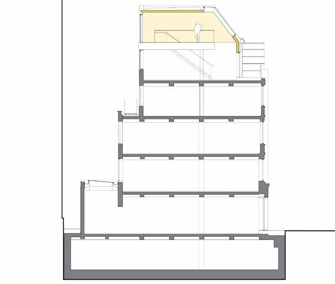
259
Section
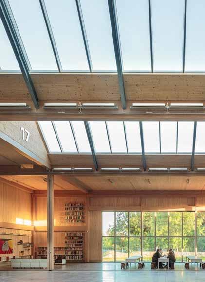
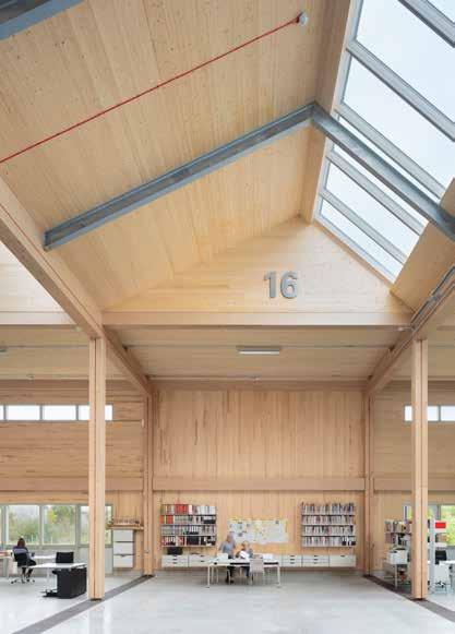
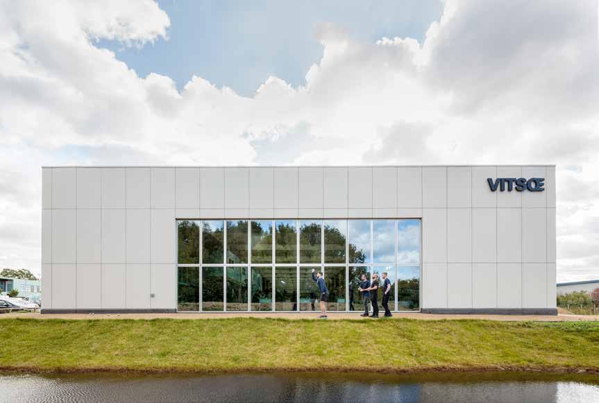
260
© Dirk Lindner
Commercial
VITSOE HEADQUARTERS
Vitsoe
LOCATION
Royal Leamington Spa
30 ft (9.2 m) / 1 storey
CONSTRUCTION COST
Undisclosed
HEIGHT / STOREYS ARCHITECT
Waugh Thistleton Architects
STRUCTURAL ENGINEER
Eckersley O’Callaghan
TIMBER ENGINEER
Hess Timber
TIMBER CONTRACTOR
Hess Timber
TIMBER MANUFACTURER
Hess Timber / Hasslacher / Pollmeier
MAIN CONTRACTOR
Inspired by the master builders working at the high point of Victorian engineering, Vitsœ’s new home brings together a rigorous and diverse group of over 30 specialists in their fields.
Built as a kit of parts the building is an extension of Vitsœ’s system-thinking which is integral to its furniture design. The building can be refined and adapted in response to the changing needs of all it serves – company, people and environment.
The first building in the UK to be made entirely of LVL, the high performance engineered hardwood structure permits beams and columns to have smaller cross sections than softwood glulam, thereby providing greater elegance to the timber structure
Spanning 445ft in length, 82ft in width and 30ft in height, the new HQ and production building is naturally ventilated and naturally lit via its northfacing saw-tooth roof-lights. Prevailing wind provides cross ventilation, while the high ceiling height allows heat to rise for comfort in summer.
TIMBER VOLUME
36,100 ft 3 (1,021 m 3)
TIMBER ASSEMBLY
6 weeks
OVERALL CONSTRUCTION
39 weeks
Windows bring the outside in, connecting employees to the surrounding landscape, while passers-by may glimpse activities within. The kitchen and dining area face directly north offering a panoramic view of the silver birch trees in the adjacent urban community woodland.
STRUCTURE TYPE
Pure Timber JCA
EMBODIED CARBON WITHIN TIMBER*
-632 tons (-574 tonnes) CO 2 e
CLT FACT
The Baubuche beams are as slender as an equivalent in steel
261
Section
2017
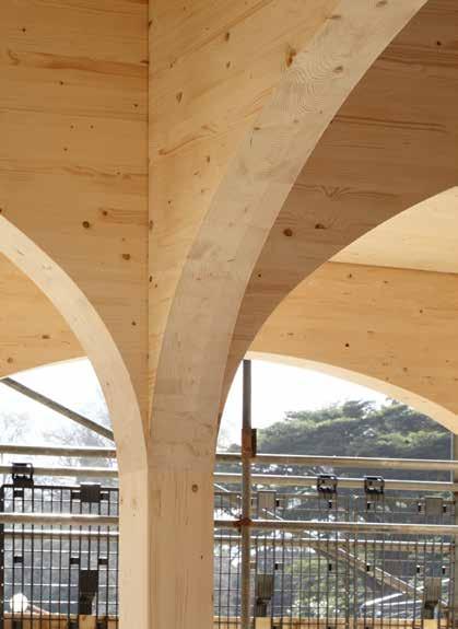
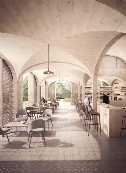

262
© Jack Hobhouse
© Forbes Massie © Jack Hobhouse
WILDERNESSE RESTAURANT
LOCATION
Sevenoaks, Kent
21 ft (6.5 m) / 1 storey
CONSTRUCTION COST
£1.9 million
HEIGHT / STOREYS ARCHITECT
Duggan Morris Architects
STRUCTURAL ENGINEER
Peter Brett Associates
TIMBER ENGINEER
Eurban
TIMBER CONTRACTOR
Eurban
TIMBER MANUFACTURER
Schilliger Holz
MAIN CONTRACTOR
Shaylor Group
TIMBER VOLUME
3,000 ft 3 (84 m 3)
TIMBER ASSEMBLY
2 weeks
The Wildernesse Restaurant is situated within a contemporary housing scheme designed as part of a holistic retirement community. The new restaurant pavilion is adjacent to the Grade II listed Wildernesse House, the origins of which can be traced back to the 13th century. The new restaurant aims to reinstate the pavilion typology of the conservatory that sat within the kitchen garden in the 19th century. Thereby creating an exquisite dining space with the transparency of a traditional glasshouse.
The design melds classical forms manufactured with the efficiency of modern methods of construction. The result is a contemporary and easy to read pavilion within a landscape steeped in heritage. CLT arches sit atop a grid of glulam columns; the timber vaults were formed of a CNC lattice structure with layers of ply overlaid. The accuracy offered by prefabrication ensured these vaults could be precisely fitted to each opening, concealing all services and joints.
The rhythm of the arches defines large glazed openings, while a central elevated lantern houses the open kitchen, creating a permeable space filled with light and expansive views across the estate. The use of minimal repeated elements is a key concept for the construction of the restaurantfrom the structural components and interior lining, to the modulation of the cladding.
50 weeks
STRUCTURE TYPE
OVERALL CONSTRUCTION Pure Timber
EMBODIED CARBON WITHIN TIMBER*
-53 tons (-48 tonnes) CO 2 e
CLT FACT
Accuracy of MMC used to create classical arched/vaulted forms
Axonometric
263
2017
Structural Diagram
Commercial Pegasus Life
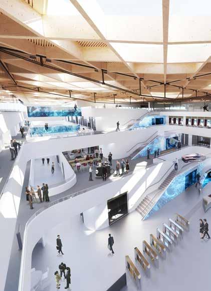
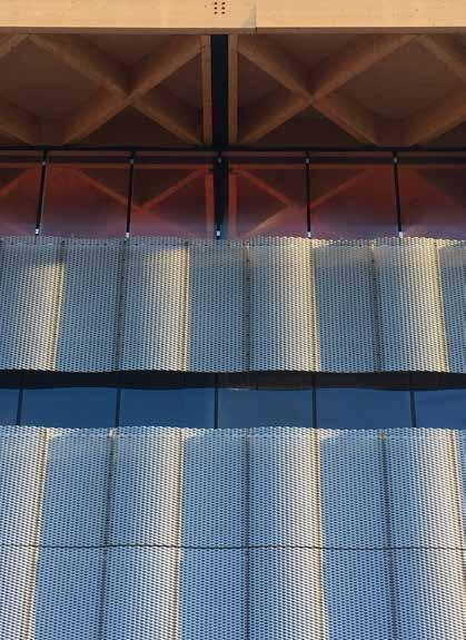
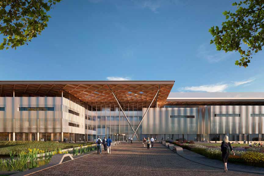
264
© Cullinan Studio / Hayes Davidson
© Cullinan Studio
© Cullinan Studio / Hayes Davidson
2018 Commercial (Education)
NATIONAL AUTOMOTIVE INNOVATION CENTRE
Jaguar Land Rover / Tata Motors European Technical Centre / WMG / University of Warwick
LOCATION
Coventry, West Midlands
HEIGHT / STOREYS
66 ft (20 m) / 4 storeys
CONSTRUCTION COST
£80 million
ARCHITECT
Cullinan Studio
STRUCTURAL ENGINEER
Arup
TIMBER ENGINEER
Arup / Engenuiti
TIMBER CONTRACTOR
B & K Structures
TIMBER MANUFACTURER
Rubner Holzbau
MAIN CONTRACTOR
Balfour Beatty
TIMBER VOLUME
84,800 ft 3 (2,400 m 3)
TIMBER ASSEMBLY
24 weeks
The NAIC brings together many elements of industrial design: commercial and academic engineering research and testing; undergraduate teaching and social functions with the objective of developing the technologies and products of the future. Designed to encourage collaboration and crossfertilisation of ideas, the building is located on a university campus and has two distinct parts: an inner sanctum and a shop window. Flexible research spaces over four storeys surround an equally flexible atrium space where people can come together. A distinctive timber roof structure acts to unify the spaces, visually tying together the closed confidential and open spaces.
The roof is a complex grid of steel, glulam and CLT. The primary grid is made of steel box-sections with additional truss elements added where greater spans are needed. A grid of glulam beams is set at 45 degrees to the primary structure and sits within the steels. The glulam is shaped on the underside to vary the depth in relation to the forces present along their length and so optimize material, made possible by the ease and accuracy of prefabrication. To facilitate the construction each beam has a tag identifying its position within the structure. The CLT roof deck gives stiffness to the roof plate while lateral support is via the stair cores. The external walls are offsite manufactured timber cassettes, combining CLT, glulam and OSB with mineral wool insulation.
150 weeks
STRUCTURE TYPE
OVERALL CONSTRUCTION Hybrid
EMBODIED CARBON WITHIN TIMBER*
-1,379 tons (-1,251 tonnes) CO 2 e
CLT FACT
Timber ‘umbrella’ roof is to be adopted across JLR projects as brand identity
265
Detail & Section
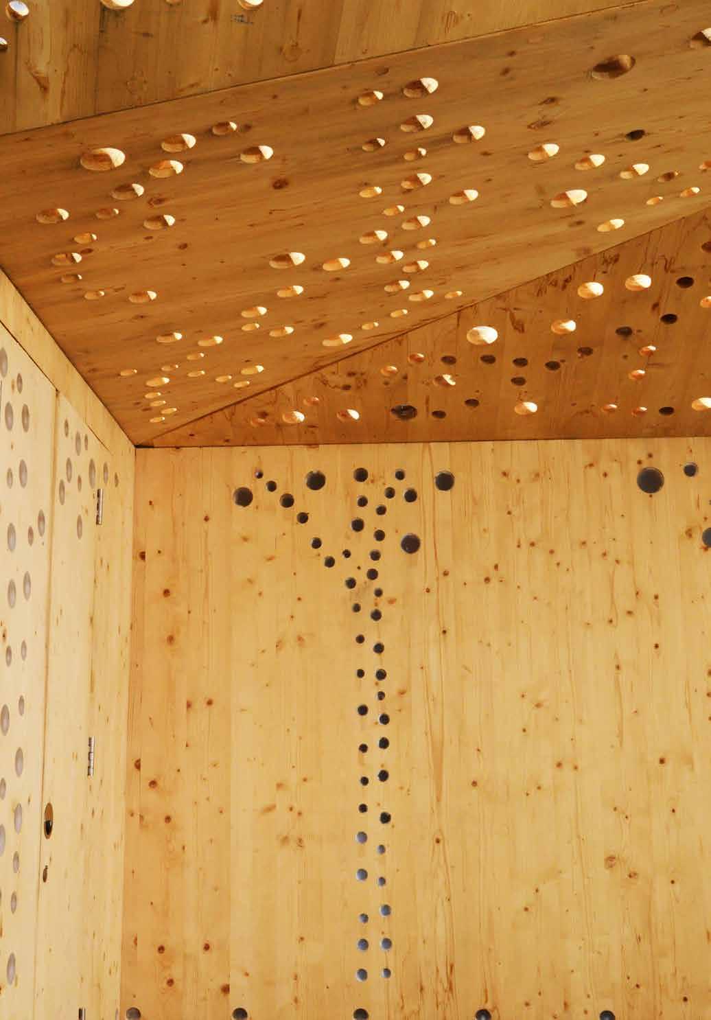
PUBLIC & CIVIC
A vast range of building uses has been grouped within this category from healthcare, sports and leisure buildings to libraries, museums and religious buildings. As such the 21 schemes within this sector are difficult to compare.
What this disparate grouping of buildings does illustrate is the flexibility that can be achieved by building with CLT and hybrid solutions, and the complexity and breadth of constraints the use of timber can help to overcome.
From construction within an existing church, where the panels had to be sized for delivery through the church door, to construction on a renovated pier 500 feet from the coast and exposed to coastal weather. CLT has proved itself to be a suitable material to address the most challenging of sites.
Some of the projects within this sector had a level of freedom that allowed for more experimentation into the possibilities of using timber. Included within this category are various installation/temporary projects that successfully worked through potential applications of CLT that had not yet been proved as viable to be used within a permanent building.
Now that CLT has proved its competitiveness, it is through the freedom of design of these schemes that architects and engineers can begin to demonstrate the full capability of CLT. Image: Glowing Orchards, Tonkin Liu © Anthony Hurren
267
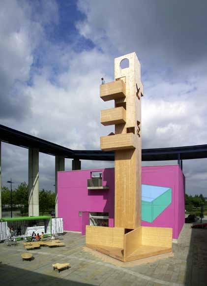
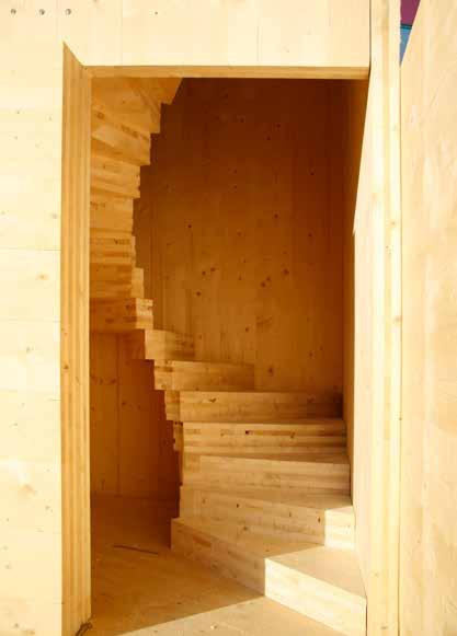
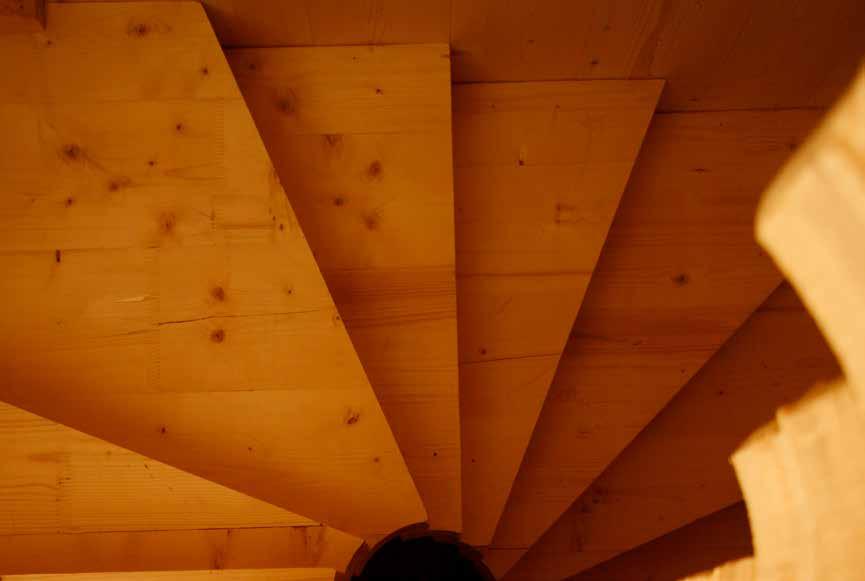
268
© Alex de Rijke / dRMM
LOCATION
Milton Keynes, Buckinghamshire
HEIGHT / STOREYS
69 ft (21 m) / 7 storeys
CONSTRUCTION COST
£25,000
ARCHITECT
dRMM
STRUCTURAL ENGINEER
Pryce & Myers
TIMBER ENGINEER
KLH UK
TIMBER CONTRACTOR
KLH UK
TIMBER MANUFACTURER
KLH Massivholz
MAIN CONTRACTOR
Steve Coleman
TIMBER VOLUME
1,400 ft 3 (39 m 3)
TIMBER ASSEMBLY
5 days
OVERALL CONSTRUCTION
7 days
Public & Civic
MK40 TOWER
Milton Keynes Gallery
Commissioned to mark the 40th anniversary of the city of Milton Keynes, this temporary installation doubled as a dynamic sculpture and an experiment in the structural capabilities of CLT.
The artwork conceptually contrasts with the predominant steel/concrete horizontality of the city, offering an opportunity for visitors to the site to climb the tower and discover views across the city. In addition it demonstrates the capacity of engineered timber to serve as building core.
MK40 is a 70ft, 7-storey freestanding vertical cantilever stair tower composed entirely of 6 inch thick CLT panels. Built on a public plaza in front of the city gallery and theatre buildings, no ground foundations were possible. Instead, the timber tower had an integral braced timber base that rests directly on paving pads on sand. No glue was used. The structure is held together by hundreds of screws, carefully positioned to deal with the transfer of wind-load from the tower to the base.
Originally intended to be shown for only two months, the prototype sculpture was in place for one year, visibly demonstrating the structural capacity of CLT to form the core stair/lift shaft for tall buildings above 4 storeys, which was the maximum to have been built at the time.
STRUCTURE TYPE
Pure CLT
EMBODIED CARBON WITHIN TIMBER*
Temporary installation proved feasibility of tall timber cores -24 tons (-22 tonnes) CO
CLT FACT
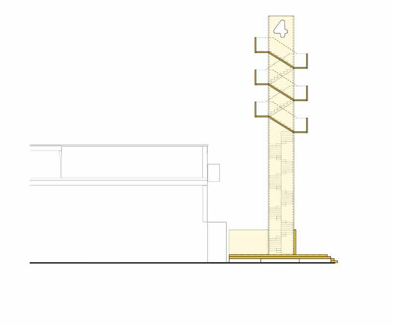
2007
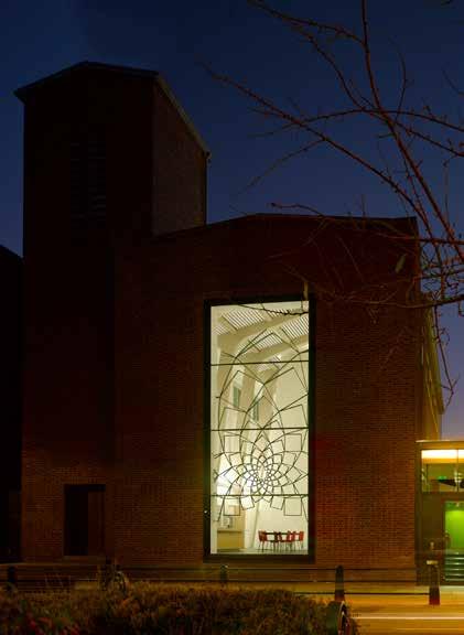

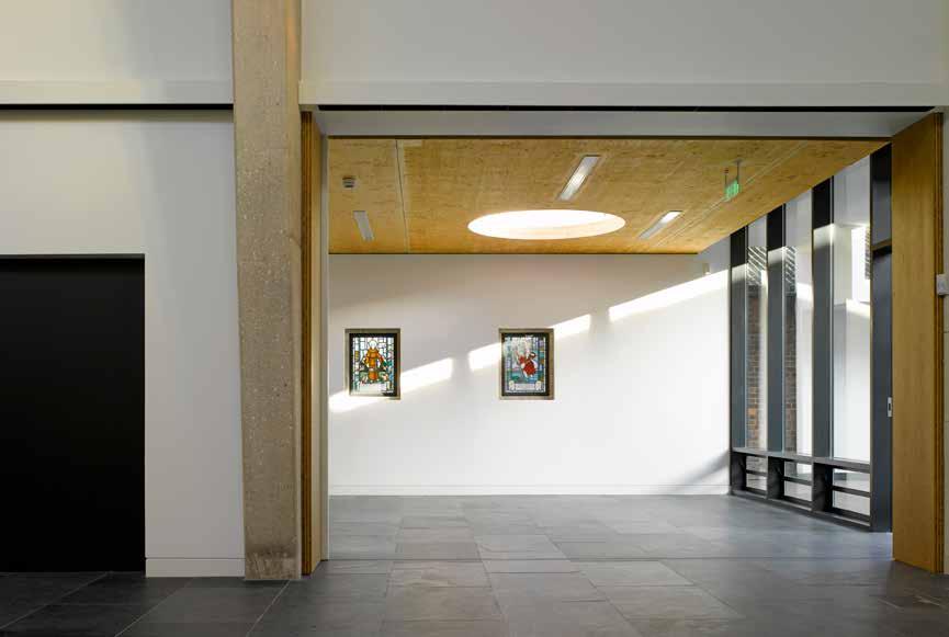
270
© Nick Kane
LOCATION
London Borough of Camden
HEIGHT / STOREYS
63 ft (19.2 m) / 1 storey
CONSTRUCTION COST
£1.8 million
ARCHITECT
Theis and Khan Architects
STRUCTURAL ENGINEER
FJ Samuely and Partners
TIMBER ENGINEER
KLH UK
TIMBER CONTRACTOR
KLH UK
TIMBER MANUFACTURER
KLH Massivholz
MAIN CONTRACTOR
Dollman Ralston
TIMBER VOLUME
2,900 ft 3 (83 m 3) 2008
TIMBER ASSEMBLY
52 weeks 3 days
OVERALL CONSTRUCTION
STRUCTURE TYPE
Pure CLT
EMBODIED CARBON WITHIN TIMBER*
-49 tons (-45 tonnes) CO 2 e
CLT FACT
CLT overcame issues of delivery and installation from a very busy road
LUMEN REFORM CHURCH
Public & Civic United Reform Church
This renovation of a 1960s church involved adding an accessible entrance, community spaces and ancillary accommodation, and creating a new courtyard garden out of the existing car park.
Using the existing concrete and brick structure as the starting point, the concept was to create a new conical 'sacred space' in the centre of the church to subdivide the area into a café and church with worship at its centre.
The 'sacred space' is the pivotal space within the church. Lit by a single source of light 36ft above floor level, the light penetrates through the roof and draws the gaze upwards towards the sky. The white render and changing light gives the space a pure and elemental feel and imbues it with a peaceful, religious aura.
To bring the church into the 21st century and open it up to the local, multifaith community, a series of single storey CLT spaces were created around the new courtyard.
CLT, selected primarily for it’s sustainable qualities, helped to overcome site access issues being lifted over the existing structures and craned directly into place. The CLT panels used for the roof of the single storey extensions are left exposed adding to the natural palette of materials.
271
Ground Floor Plan

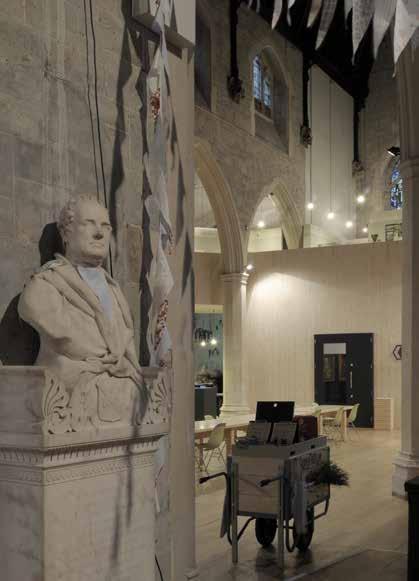
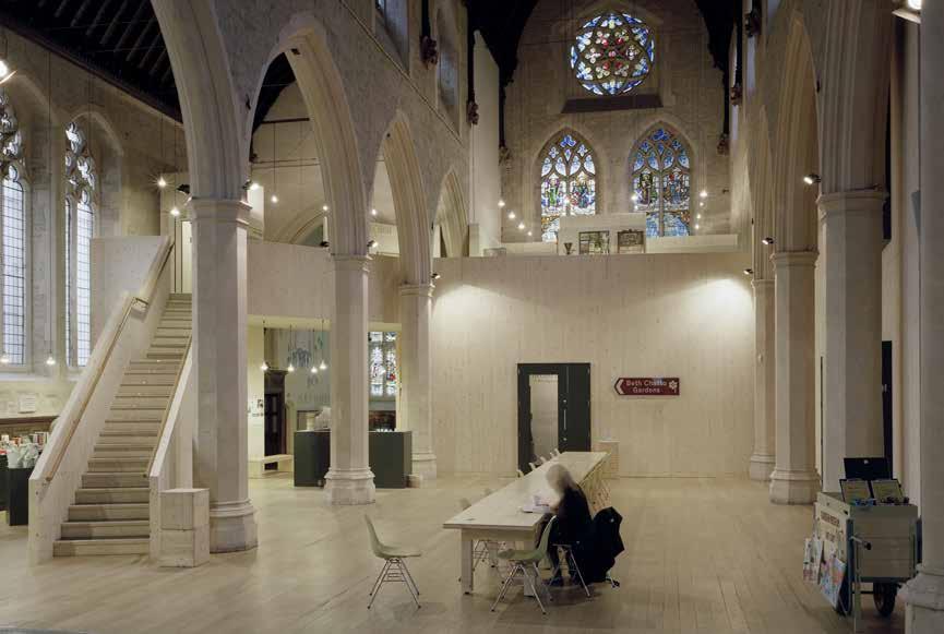
272
© David Grandorge
London Borough of Lambeth
22 ft (6.6 m) / 2 storeys
CONSTRUCTION COST
£300,000
ARCHITECT
Dow Jones Architects
STRUCTURAL ENGINEER
TIMBER ENGINEER
TIMBER CONTRACTOR
TIMBER MANUFACTURER
MAIN CONTRACTOR
TIMBER VOLUME
TIMBER ASSEMBLY
OVERALL CONSTRUCTION
STRUCTURE TYPE
EMBODIED CARBON WITHIN TIMBER*
CLT FACT
Adaptability
Public & Civic The Garden Museum
THE GARDEN MUSEUM
The architectural concept was to create a lightweight belvedere that could sit independently within the nave of a Grade II* listed church. The belvedere structure enables the placement of the temporary gallery at ground floor level, moving the permanent collection, from its former location in the nave, up to the new first floor level and providing additional space for the museum’s cultural programs.
The natural finish of the timber shares a close tonal similarity with the existing limestone walls, complimenting the original decorative accents, such as the stained glass windows, mahogany and vaulted ceilings.
The architects were drawn towards CLT due to the constraints of the existing fabric and archeology of the church. The structural components of the design were limited by what could be brought into the church, and how they could be maneuvered once inside the space. The designed was tailored to these dimensional constraints with widths limited to 20ft to allow the prefabricated panels to be brought in through the existing doors of the church. The structure was then assembled within the nave, the dry environment of which was particularly well suited to the physical characteristics of timber.
Due to the weight of CLT no additional foundations were required which ensured any archeology beneath the church could remain undisturbed.
273
LOCATION
CLT Redwing
HEIGHT / STOREYS Pure
Eurban -57
tonnes) CO 2 e 13 weeks 2 weeks 3,200 ft 3 (90 m 3)
2009
of panel dimensions allowed for construction inside nave
tons (-52
Schilliger Holz Eurban Momentum Consulting Engineers
Sectional Axonometric
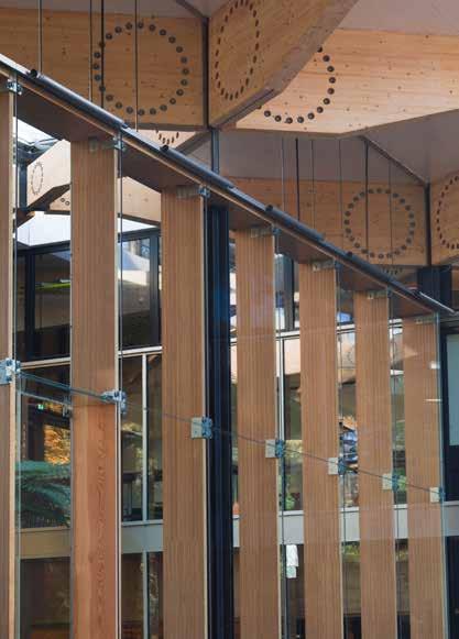
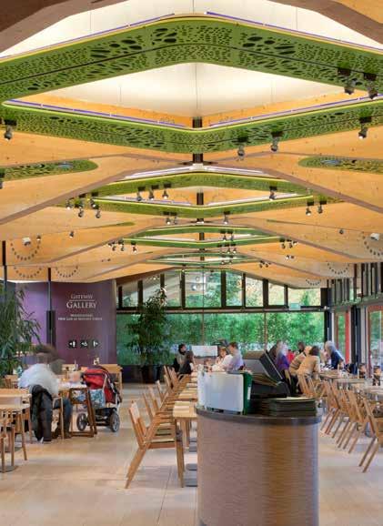
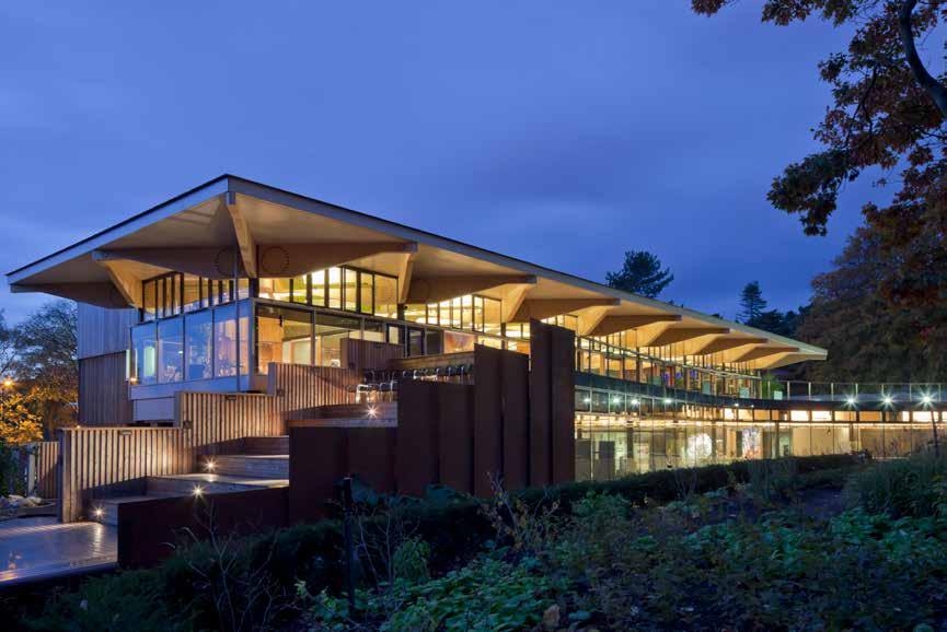
274
© Paul Raftery
2009 Public & Civic
JOHN HOPE GATEWAY
Royal Botanic Garden Edinburgh
LOCATION
Edinburgh, Lothian
34 ft (10.5 m) / 2 storeys
CONSTRUCTION COST
£10.7 million
HEIGHT / STOREYS ARCHITECT
Cullinan Studio
STRUCTURAL ENGINEER
BuroHappold Engineering
TIMBER ENGINEER
BuroHappold Engineering / Techniker
TIMBER CONTRACTOR
Donaldson & McConnell
TIMBER MANUFACTURER
KLH Massivholz
MAIN CONTRACTOR
As the ‘front door’ to one of the world’s leading botanical institutions, the building captures the spirit of the Royal Botanic Garden Edinburgh, communicating the energy and enthusiasm for the world of plants that drives the scientists and researchers.
Respecting the pre-eminence of the Garden, the architecture frames views and is woven into the contours and routes of the landscape, defining the threshold of a compelling journey to come. A striking ‘floating’ timber canopy celebrates the concept of a gateway and the desire for a demonstrably timber building.
This timber canopy is designed to create coffered roof spaces that give an individual identity to the restaurant and other areas. Floating over the entire building as a single horizontal timber plane it is formed from CLT panels supported by a diagonal lattice of 117 exposed tapered glulam beams.
TIMBER VOLUME
23,800 ft 3 (674 m 3)
TIMBER ASSEMBLY
23 weeks
OVERALL CONSTRUCTION
95 weeks
The roof beams are bolted to steel flitch plates with the bolts in a circular pattern connecting to the most slender columns possible, composed of four steel angles. Columns of this nature have been used historically to create compression elements of minimum material, yet here they are expressed and celebrated, allowing glimpses through the column and portraying a fluted form to emphasize their verticality.
STRUCTURE TYPE
Hybrid Xircon
EMBODIED CARBON WITHIN TIMBER*
-403 tons (-366 tonnes) CO 2 e
CLT FACT
This project was the first use of CLT for a public building in Scotland
275
Section


276
© Joseph Burns
2009 Public & Civic Pestival
THE TERMITE PAVILION
LOCATION
Temporary installation
HEIGHT / STOREYS
20 ft (6.1 m) / 1 storey
CONSTRUCTION COST
Undisclosed
ARCHITECT
Softroom Limited
STRUCTURAL ENGINEER
Atelier One
TIMBER ENGINEER
Atelier One
TIMBER CONTRACTOR
KLH UK
TIMBER MANUFACTURER
KLH Massivholz
MAIN CONTRACTOR
KLH UK
TIMBER VOLUME
6,800 ft 3 (192 m 3)
TIMBER ASSEMBLY
2 days
OVERALL CONSTRUCTION
2 days
Built for the insect inspired festival, Pestival, the Termite Pavilion is a 20 foot cube, walk-in structure based on a three dimensional scan of an actual termite mound in Namibia. Scaled up fifteen times to allow humans to move through it, the installation features sound recordings from inside a termite mound and lighting that dims and brightens to emulate breathing.
The scan was created by pouring gypsum into the termite mound, then physically slicing the mound in 1mm horizontal increments for digital capture. To optimize the panel use, the computer model was sliced horizontally into 51 layers, each of which became the template for the CNC routing of the complex internal profiles of the termite mound onto the CLT.
Formed in blocks of six layers of maximum size of 8 foot, due to transport constraints, the pieces were lifted into place, bearing on top of each other and aligned in place with vertical threaded bars and horizontally with bolted connections. The overall structure is stable under its own weight, nevertheless some vertical ties were required to counteract local overturning of some blocks cantilevering at the top of the pavilion.
A CLT and plywood plinth forms a base for the structure transferring loads to the existing pavement and providing level access for visitors into the pavilion.
STRUCTURE TYPE
Pure CLT
EMBODIED CARBON WITHIN TIMBER*
-120 tons (-109 tonnes) CO 2 e
CLT FACT
CNC routing facilitated replication of complex organic form
277
Section
50 1000 1500 2000 mm
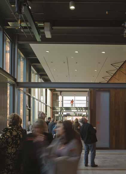
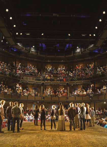
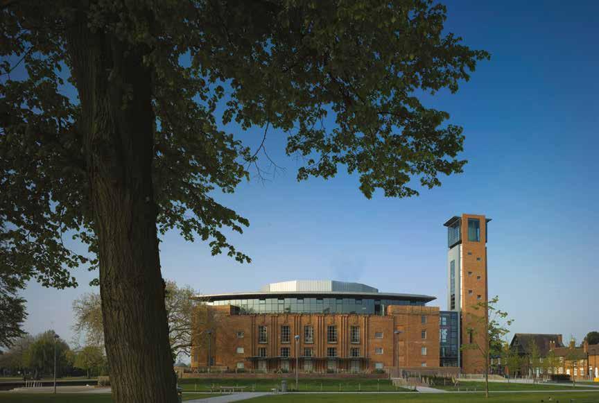
278
© Peter Cook
© Bennetts Associates © Bennetts Associates
2010
Public & Civic
ROYAL SHAKESPEARE THEATRE
The Royal Shakespeare Company
LOCATION
Stratford-upon-Avon, Warwickshire
HEIGHT / STOREYS
118 ft (36 m) / 3 storeys
CONSTRUCTION COST
£57.7 million
ARCHITECT
Purpose-built in the 1930s the Royal Shakespeare Theatre has a picturesque riverside site in Stratford-upon-Avon. For 70 years the building’s lack of foyer space hampered the work of the theatre. This project involved rebuilding and transforming the existing, Grade II* listed, theatre buildings and incorporating a brand new auditorium.
STRUCTURAL ENGINEER
BuroHappold Engineering
TIMBER ENGINEER Bennetts Associates
BuroHappold Engineering
TIMBER CONTRACTOR
KLH UK
TIMBER MANUFACTURER
KLH Massivholz
MAIN CONTRACTOR
The design focused on creating stronger connections between actors, audiences, building, and town with significant changes to the theatre required to re-organize the public spaces. A new auditorium was conceived where nobody would sit more than 50ft from the stage. The building was opened on all four sides, creating additional foyers and linking them to a wider masterplan which positively connected the theatre to the town.
A lightweight solution was required to allow for the insertion of a new auditorium space to be partially carried on existing walls. A hybrid steel and CLT frame, connecting in some places to the retained historic masonry, was designed for some of the key new-build elements including the four storey dressing room block and new foyer spaces.
TIMBER VOLUME
23,200 ft 3 (658 m 3)
TIMBER ASSEMBLY
6 weeks
OVERALL CONSTRUCTION
159 weeks
The lighter weight of the timber allowed the use of mini-piles removing the requirement for significant temporary works associated with creating a piling platform over the river.
STRUCTURE TYPE
Hybrid Mace
EMBODIED CARBON WITHIN TIMBER*
-404 tons (-367 tonnes) CO 2 e
CLT FACT
A significant cost saving was made by reduced mini pile foundations
279
Section
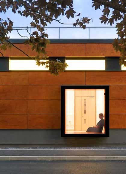

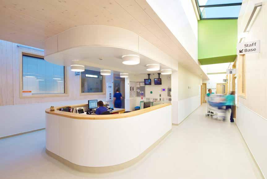
280
© Craig Auckland Fotohaus
Bath, Somerset LOCATION
HEIGHT / STOREYS
21 ft (6.3 m) / 1 storey
CONSTRUCTION COST
£3 million
ARCHITECT
Feilden Clegg Bradley Studios
STRUCTURAL ENGINEER
BuroHappold Engineering
TIMBER ENGINEER
BuroHappold Engineering /KLH UK
TIMBER CONTRACTOR
Public & Civic (Healthcare)
DYSON
CENTRE FOR NEONATAL CARE
Royal United Hospital
The Dyson neo-natal care centre was the first use of solid laminated timber in a tertiary healthcare environment. This single storey extension was designed to support the ‘developmental care’ model, providing space and privacy for parents to engage with their babies. The layout is intended to be legible to users with a clear, spiral progression around the central staff base, from intensive care through to special care.
The unit has been designed to provide the spaces with a visual connection to the outside, the changing day and seasons whilst minimizing reliance on artificial light. This controlled daylight provides an excellent working environment whilst allowing babies to develop an awareness of the diurnal cycle.
The timber solution provided a quick, clean and quiet form of construction; essential in an acute healthcare environment. It also provided an opportunity to challenge healthcare construction, and look at a more sustainable material with a low embodied energy.
TIMBER MANUFACTURER
KLH Massivholz
MAIN CONTRACTOR
Vinci Construction
TIMBER VOLUME
11,600 ft 3 (329 m 3)
TIMBER ASSEMBLEY
3.5 weeks
OVERALL CONSTRUCTION
52 weeks
A palette of natural materials alongside the exposed CLT creates a sense of calm bringing warmth and tactility to the clinical facility. Combined with the quality of daylight and sunlight, this helps lower stress levels and lifts the spirits of the parents, staff and infants being treated.
STRUCTURE TYPE
Pure CLT
EMBODIED CARBON WITHIN TIMBER*
KLH UK -203 tons (-184 tonnes) CO 2 e
CLT FACT
First use of CLT in tertiary healthcare environment
281
2011 Section
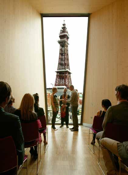
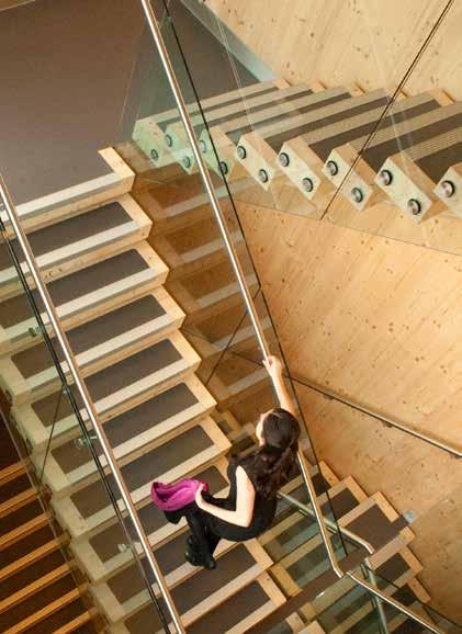
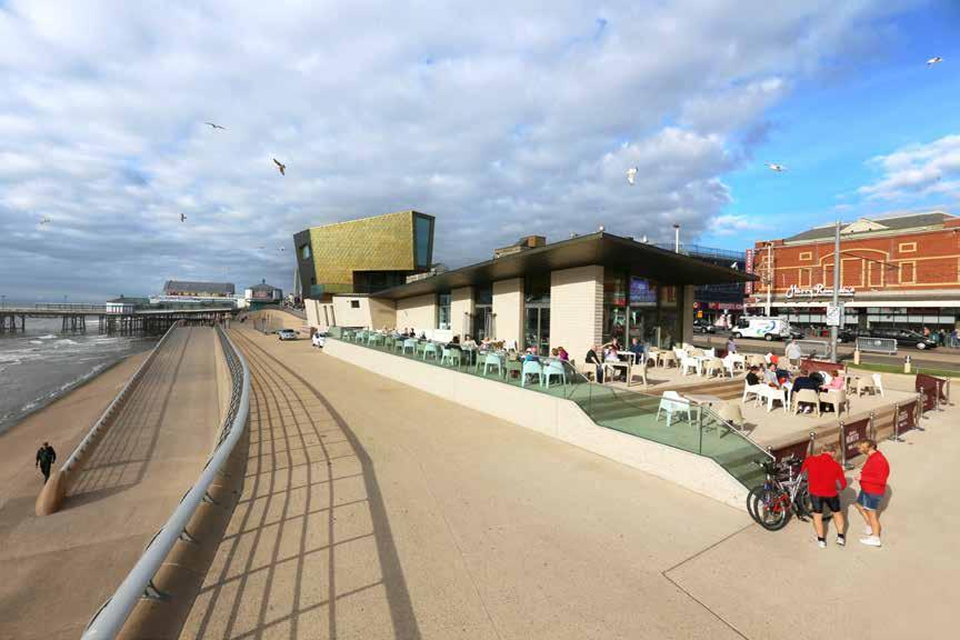
282
/
© Alex de Rijke
dRMM
Public & Civic
TOWER OF LOVE
Blackpool Council
LOCATION
47 ft (14.4 m) / 3 storeys
CONSTRUCTION COST
Undisclosed
HEIGHT / STOREYS ARCHITECT
Blackpool, Lancashire dRMM
STRUCTURAL ENGINEER
Michael Hadi Associates
TIMBER ENGINEER
Michael Hadi Associates
TIMBER CONTRACTOR
Züblin Timber (formerly Finnforest Merk)
Commissioned as a new landmark that would celebrate Blackpool’s confidence as a traditional seaside resort, the ‘Tower of Love’ pavilion was the first building built on the Golden Mile for a great many years. It provides a focal point for visitors; a large restaurant and local information office at promenade level, with registry offices and ceremony hall above.
Designed as a ‘useful sculpture,’ the structure is a ‘telescopic’ wedding tower. A vertical view of Blackpool Tower frames the space in which couples exchange vows, while horizontal views of the Irish Sea are created in the Registry, reception, roof terrace and restaurant.
Blackpool is an extremely demanding marine environment. High wind speeds, constant driven rain and sand, extreme weather patterns, high humidity and extreme general exposure all contribute to one of the most robust environmental contexts in the UK. The architectural content of the Tower Festival Headland responds in an equally robust manner.
Züblin Timber (formerly Finnforest Merk)
MAIN CONTRACTOR
TIMBER VOLUME
12,700 ft 3 (360 m 3)
TIMBER ASSEMBLY
4.5 weeks
OVERALL CONSTRUCTION
Standing on a stepped concrete plinth containing recycled and phosphorescent glass, the CLT building is deliberately eye-catching. Clad in golden stainless steel shingles the form and detailing is a celebration of Blackpool’s renowned exuberance, combining the bracing coastal weather with sustainable construction and a sensual, wooden interior.
TIMBER MANUFACTURER Pure Timber Parkinson Building Contractor
STRUCTURE TYPE
EMBODIED CARBON WITHIN TIMBER*
65 weeks -221 tons (-200 tonnes) CO 2 e
CLT FACT
The first public registry office in the UK to be built from CLT
283
2012 Section
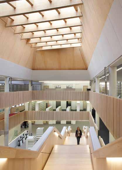

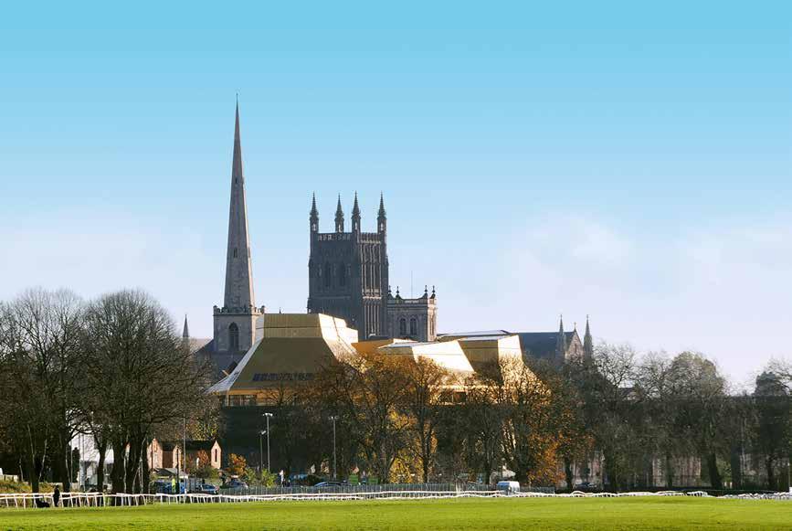
284
© Feilden Clegg Bradley Studios
© Hufton + Crow © Hufton + Crow
LOCATION
HEIGHT / STOREYS
88 ft (26.8 m) / 5 storeys
CONSTRUCTION COST
£35.8 million Worcester, Worcestershire
The Hive is the first fully integrated public and university library in the UK. This cultural centre is home to an academic library for students, a public library, the county archives, and a local history centre.
Feilden Clegg Bradley Studios
STRUCTURAL ENGINEER ARCHITECT
Hyder Consulting (UK) Ltd / Atelier One Atelier One
Positioned on the riverbank, the building is designed as a counterpoint to the city cathedral and a beacon for learning. An extruded roof is formed of a series of irregular laminated timber cones that echo the undulating ridgeline of the Malverns and the historic kilns of the Royal Worcester Pottery. The cones divide the building into a series of conjoined blocks reflecting the arrangement of rooms within. Parametric software was developed during the project to manage the fine tuning of the complex roof geometries to optimize natural lighting and ventilation throughout the building.
TIMBER ENGINEER
TIMBER CONTRACTOR
KLH UK
TIMBER MANUFACTURER
KLH Massivholz
MAIN CONTRACTOR
The interior is conceived as a ‘social landscape’. A series of balconies, staircases and ramps allow users to move around the building freely. The central atrium’s double height, ash-lined interior brings the timber of the roof into the heart of the building.
Sustainability was a high priority throughout. The CLT roof generated a saving of more than 2,200 tons of CO 2 compared to the initial design in steel. Water from the river Severn provides peak cooling and locally sourced biomass provides heating.
TIMBER VOLUME
55,100 ft 3 (1,559 m 3)
TIMBER ASSEMBLY
17 weeks
OVERALL CONSTRUCTION
104 weeks
STRUCTURE TYPE
Hybrid Galliford Try
EMBODIED CARBON WITHIN TIMBER*
-950 tons (-862 tonnes) CO 2 e
CLT FACT
Compatability with software allowed fine tuning of the roof form
285
Section 2012 Public & Civic
of Worcester
HIVE
University
THE
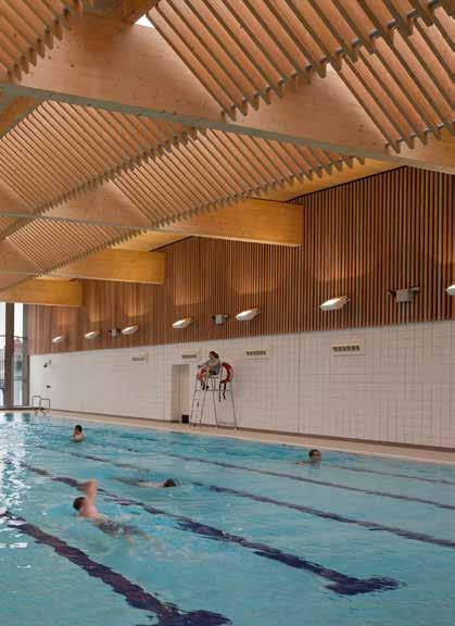
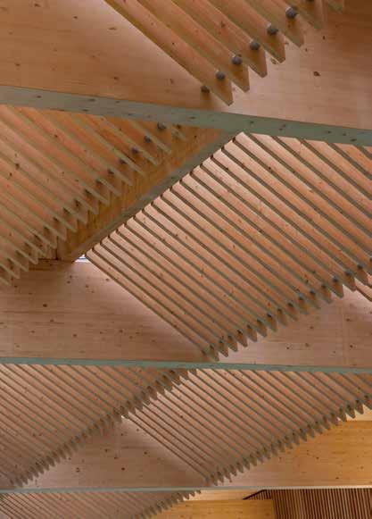
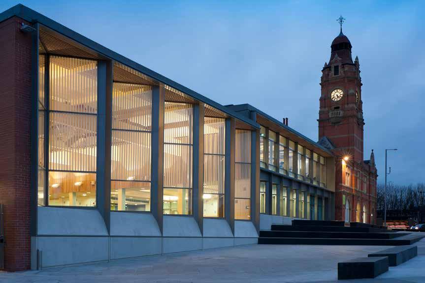
286
© Martine Hamilton Knight
23 ft (7 m) / 3 storeys Nottingham, Nottinghamshire
VICTORIA LEISURE CENTRE
Unable to restore the original Victorian bath house to contemporary standards, the decision was made to pursue a hybrid option that retained the 1890s clock tower as the entrance to a new state of the art facility, with a community pool, fitness suite and café.
CONSTRUCTION COST
£5.5 million Levitate
ARCHITECT
STRUCTURAL ENGINEER
Furness Partnership
TIMBER ENGINEER
TIMBER CONTRACTOR
TIMBER MANUFACTURER
MAIN CONTRACTOR
TIMBER VOLUME
TIMBER ASSEMBLY
OVERALL CONSTRUCTION
The new façade is designed to sit in harmony with the clock tower, while resolving level changes and edge conditions relating to the newly pedestrianized market square outside. Key to this is the concertina screen façade that exploits opacity and orientation, not only in response to key functional requirements such as the need to reduce glare for the lifeguards, but also in creating a balance between engagement and privacy.
The pool hall is designed to have a calm warmth. This is achieved by generous proportions, the use of natural materials for the roof structure, an abundance of controlled natural light, and an absence of ventilation paraphernalia. The roof structure is formed of glulam beams with CLT panels and, despite the high humidity of the space, timber offered a low maintenance solution.
Extensive physical and computer models were used to generate the concepts for the building and to ensure that they were delivered in a cost effective and efficient manner during the construction stage, which contributed to the project being completed several months ahead of schedule.
STRUCTURE TYPE
HEIGHT / STOREYS Hybrid Carillion Building
EMBODIED CARBON WITHIN TIMBER*
CLT FACT
CLT and glulam roof used in high humidity environment
287
LOCATION
& K
Section
B
Structures -31 tons (-28 tonnes) CO 2 e 1,800 ft 3 (50 m 3)
& K
70 weeks 1 week Binderholz B
Structures
2012 Sports & Leisure (Public & Civic) Nottingham City Council
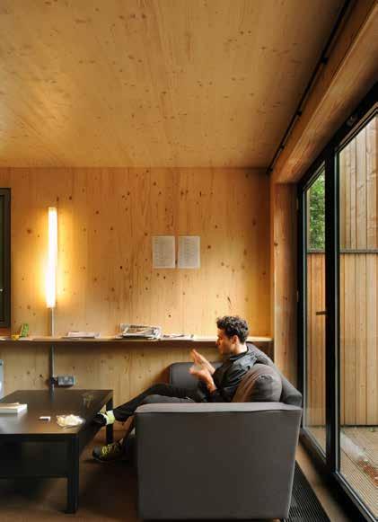
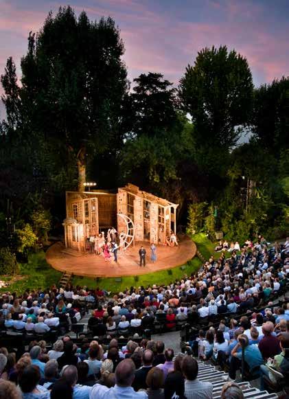
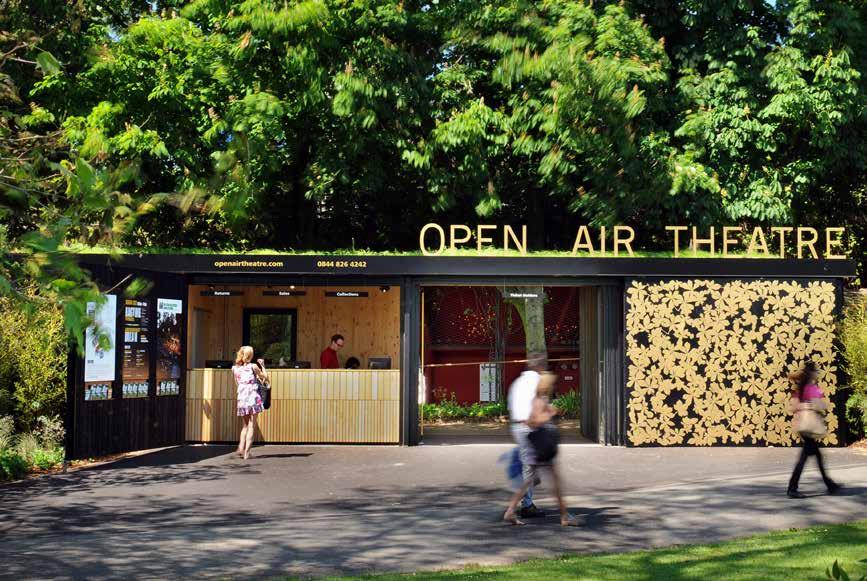
288
© Philip Vile
REGENTS PARK OPEN AIR THEATRE
The Open Air Theatre
London Borough of Camden
HEIGHT / STOREYS
18 ft (5.6 m) / 1-2 storeys
CONSTRUCTION COST
£1.9 million
ARCHITECT
Haworth Tompkins
STRUCTURAL ENGINEER
Eurban Price & Myers
TIMBER ENGINEER
TIMBER CONTRACTOR
TIMBER MANUFACTURER
Stora Enso
MAIN CONTRACTOR
The series of new timber buildings are designed to read as a coherent ensemble within Regent’s Park. A black stained larch outer perimeter houses the backstage facilities and box office and forms a protective layer. Inside the perimeter the smaller structures are clad in natural timber. This combination of timbers being complimentary to the mature landscape setting, echoing the repetitive verticality of the trees they sit amongst.
On the backstage building the rough sawn dark larch cladding is cut back at window openings revealing vertical bands of finer, untreated timber. Along the north-west façade the windows are narrow but extend from desk height to soffit to maximize daylight penetration. Whilst their articulation may appear random, their positioning relates to the internal configuration. The window slots animate the façade and help to reduce the effects of light spillage after daylight hours, while the stage side elevations have limited fenestration to avoid potential light spillage towards the stage.
TIMBER VOLUME
CLT was used as both a direct contextual reference to the surrounding trees, and for its environmental and practical advantages. The use of CLT panels allowed for construction within the 6-month window between theatre seasons and the lightweight structure required relatively small foundations, preserving the mature tree roots of the historic park. Exposed internally the use of CLT reduced wet trades on site, key for its natural setting. 2012
TIMBER ASSEMBLY
OVERALL CONSTRUCTION
STRUCTURE TYPE
EMBODIED CARBON WITHIN TIMBER*
CLT FACT
Ashe Construction Hybrid Weight
289
LOCATION
of CLT reduced foundations protecting the roots of mature trees
Ground Floor Plan
3
-118 tons (-107 tonnes) CO 2 e
Eurban
30 weeks
weeks
6,600 ft 3 (186 m 3)
Civic
Public &

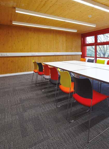
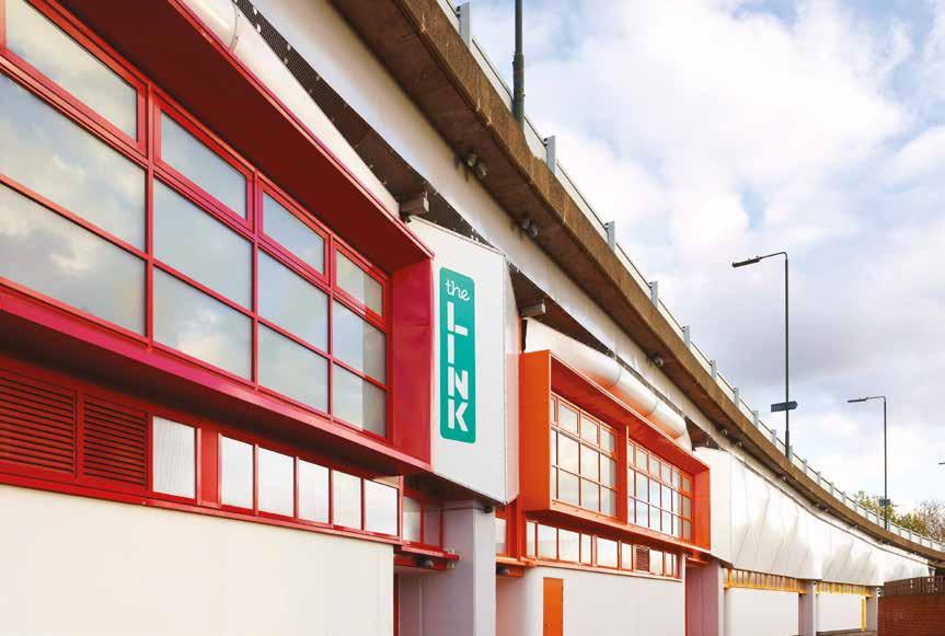
290
© Saville Jones Architects
/ Alphabetical
LOCATION
London Borough of Bexley
HEIGHT / STOREYS
21 ft (6.3 m) / 2 storeys
CONSTRUCTION COST
£5.7 million
ARCHITECT
Saville Jones Architects
STRUCTURAL ENGINEER
Furness Partnership
TIMBER ENGINEER
KLH UK
TIMBER CONTRACTOR
KLH UK
TIMBER MANUFACTURER
KLH Massivholz
MAIN CONTRACTOR
Grehan Contractors
TIMBER VOLUME
10,600 ft 3 (300 m 3)
TIMBER ASSEMBLY
2 weeks
OVERALL CONSTRUCTION
104 weeks
Public & Civic YOUTH LEISURE ZONE
Trust Thamesmead
The Link is a world class youth facility, offering an exciting range of activities for the young people of Thamesmead. The facilities are ingeniously provided beneath a highway, the site being defined by a series of concrete arches supporting the fly-over above.
This previously undeveloped land that had been neglected and abused, presented a unique opportunity. To maximize the use of such an area and utilize the structure for shelter is a beautifully simple concept. The design explored how to turn this physical, ‘hard’ space into a carefully defined, tangible building focused on youth facilities providing a diversity of functions including a dance/drama studio, recording studio, climbing wall, fitness gym and a workshop for teaching motorcycle maintenance.
Due to the constraints imposed by the highway authorities, no structural loads could be asserted on the existing highway structure. As a result of this and the context, the method of construction was required to be light, prefabricated and easy to assemble. CLT pods are supported directly on glulam ‘V’ supports with no loads affecting the highway structure.
The building is bold and colorful, while materials chosen are ‘softer’ than the concrete that encloses them. Freestanding CLT pods and tensile fabric completes the spaces, and act as a curtain pulled across its façade.
STRUCTURE TYPE
Pure Timber
EMBODIED CARBON WITHIN TIMBER*
-195 tons (-177 tonnes) CO 2 e
CLT FACT
Timber offered a cost and time saving over an equivalent steel structure
291
2013 Section
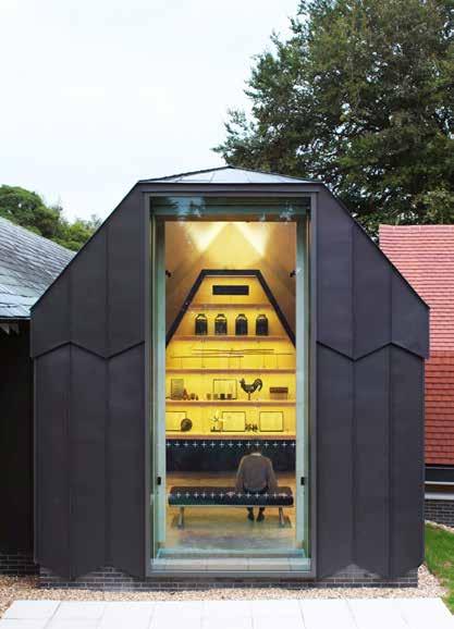


292
© Brotherton-Lock
LOCATION
Ditchling, East Sussex
HEIGHT / STOREYS
23 ft (7 m) / 1 storey
CONSTRUCTION COST
£1.2 million
ARCHITECT
Adam Richards Architects
STRUCTURAL ENGINEER
Price & Myers
TIMBER ENGINEER
KLH UK
TIMBER CONTRACTOR
KLH UK
TIMBER MANUFACTURER
KLH Massivholz
MAIN CONTRACTOR
Westridge Construction
TIMBER VOLUME
2,500 ft 3 (72 m 3)
TIMBER ASSEMBLY
1.5 weeks
OVERALL CONSTRUCTION
60 weeks
Public & Civic
DITCHLING MUSUEM OF ART AND CRAFT
Ditchling Museum of Art & Craft
This project combines a disparate collection of existing buildings: a cottage, a Victorian school building, and a derelict cart lodge, to form a new museum of the Arts and Crafts Movement, within a historic village setting.
Sitting on the borders of the village green, and surrounded by listed buildings the new elements were designed to be sympathetic to the context without resorting to pastiche. Two new buildings were inserted between the cart lodge and the main galleries providing new facilities and connecting spaces. Internally the museum’s orientation has been reversed with the cart lodge becoming a new entrance and cafe/shop. The first gallery space encountered within the musuem is constructed in CLT. Chosen for its environmental credentials the use of CLT ensured the swift assembly of this new build element on site. Exposed within, the timber creates a warm welcoming atmosphere for the spaces of the museum, and speaks to the principles of ‘truth to materials’ that inspired the Arts & Crafts Movement.
The sustainability agenda for the scheme is evident in the refurbishment and reuse of the existing structures and the choice of low embodied carbon materials for the new elements. The new building is clad in high performance insulation and black zinc panels with serrated detailing. Both unusual and beautiful, this material has a long life-span, requires no maintenance and can be easily recycled at the end of its life.
STRUCTURE TYPE
Pure CLT
EMBODIED CARBON WITHIN TIMBER*
-44 tons (-40 tonnes) CO 2 e
CLT FACT
CLT enabled creation of a large open volume without any cross-bracing
293
2013 Ground Floor Plan
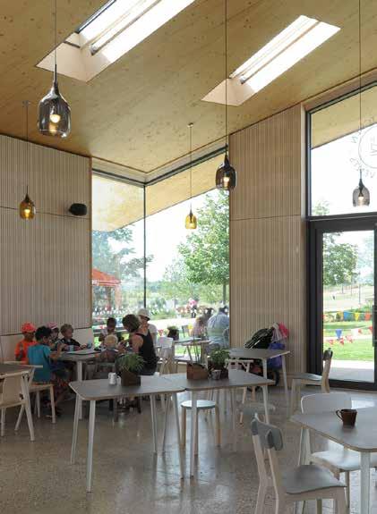
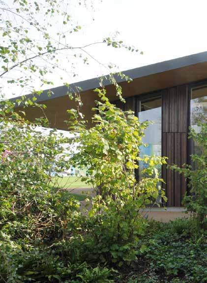
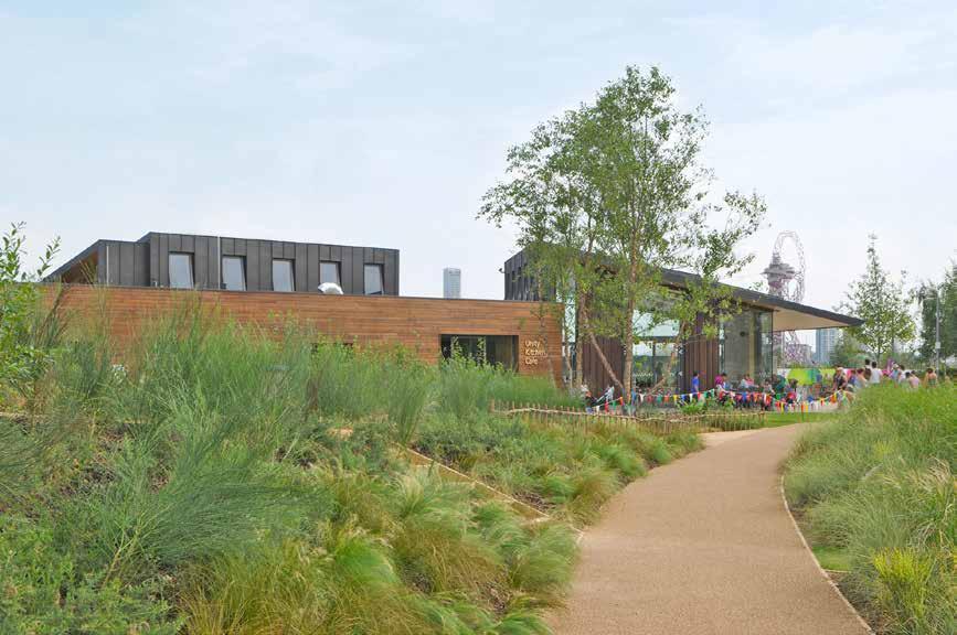
294
© David Grandorge
LOCATION
London Borough of Newham
HEIGHT / STOREYS
18 ft (5.5 m) / 1 storey
CONSTRUCTION COST
Undisclosed
ARCHITECT
Erect Architecture
STRUCTURAL ENGINEER
Entuitive (formerly TALL)
TIMBER ENGINEER
Entuitive (formerly TALL)
TIMBER CONTRACTOR
Zublin Timber (formerly Finnforest Merk)
TIMBER MANUFACTURER
Zublin Timber (formerly Finnforest Merk)
MAIN CONTRACTOR
BAM Nuttall
TIMBER VOLUME
7,400 ft 3 (210 m 3)
TIMBER ASSEMBLY
2.5 weeks
OVERALL CONSTRUCTION
28 weeks
Public & Civic
OLYMPIC PARK TIMBER LODGE
London Legacy Development Corporation
Designed as a community hub the timber lodge and surrounding play area are a continuation of the landscaped Olympic Park with its large-scale buildings, powerful and fluid landforms, sweeps of planting and its focus on connectivity, movement and ecology.
The lodge contains a café, community space and public toilet provision for the north park. Located at the intersection of main pedestrian and cycle pathways, the café enjoys views in three directions with the community room opening on to the intimate grass lawn enclosed by hazel woodlands. Designed as integral to the landscape, landforms and planting conceal and reveal the lodge building as visitors move through the park. The boundary between internal and external spaces is merged, the spaces relating to each other and the wider context of the park.
The structure is CLT with the panels used to their full structural capacity to provide covered external space underneath slender cantilevering roof overhangs, that would otherwise have required downstand beams. The rhythm of the façade reads as natural extension of the multi-stem hazel woodland. Whilst inside the exposed CLT is complemented by pale timber furnishings and large windows provides a light, airy space which retains a connection to the park outside.
STRUCTURE TYPE
Pure Timber
EMBODIED CARBON WITHIN TIMBER*
-132 tons (-120 tonnes) CO 2 e
CLT FACT
CLT allowed roof overhang without downstand beams
295
2013
Ground Floor Plan
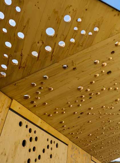


296
© Anthony Hurren
© Mike Tonkin © Anthony Hurren
2014 Public & Civic
GLOWING ORCHARD
Kingston upon Thames Council
LOCATION
Royal Borough of Kingston upon Thames
HEIGHT / STOREYS
9 ft (2.8 m) / 1 storey
CONSTRUCTION COST
£320,000
ARCHITECT
Tonkin Liu
STRUCTURAL ENGINEER
Rodrigues Associates
TIMBER ENGINEER
Rodrigues Associates
TIMBER CONTRACTOR
KLH UK
TIMBER MANUFACTURER
KLH Massivholz
MAIN CONTRACTOR
Balfour Beatty
TIMBER VOLUME
Consisting of 75,000 square feet of public space and 26 market stalls ranging from fishmongers, butchers and greengrocers, to bread-makers and lunchtime food stalls, the market in Kingston upon Thames is one of the oldest in the UK with surviving records that date back to the early thirteenth century. The insertion of a series of new timber structures have diversified the ancient market place, which can now be used in the evening for dining, and performances, breathing new life into an area which had been largely abandoned by the local community.
The configuration and layout of these new market stalls adhere to the strict mechanics and psychology of markets, and the stalls themselves are adaptable for different displays and produces as the nature of markets dictates that proprietors will change over time.
Chosen for its visual reference to Tudor timber structures as well as its durability, adaptability, and tactility, the texture and color of the untreated CLT is visually harmonious with the architectural heritage of the Market House at the centre of the ancient Market Place.
The CNC routed perforation across the roof and wall panels becomes a light artwork when dusk falls transforming the stalls into lanterns, and creating a new sense of place, a “Glowing Orchard”.
TIMBER ASSEMBLY
6 weeks
OVERALL CONSTRUCTION
24 weeks 1,200 ft 3 (34 m 3)
STRUCTURE TYPE
Hybrid
EMBODIED CARBON WITHIN TIMBER*
-19 tons (-17 tonnes) CO 2 e
CLT FACT
CNC routing allowed the design of ‘orchards’ through perforations
297
Section
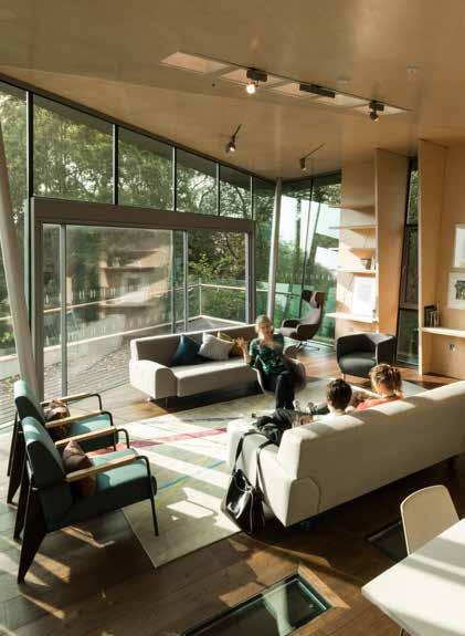
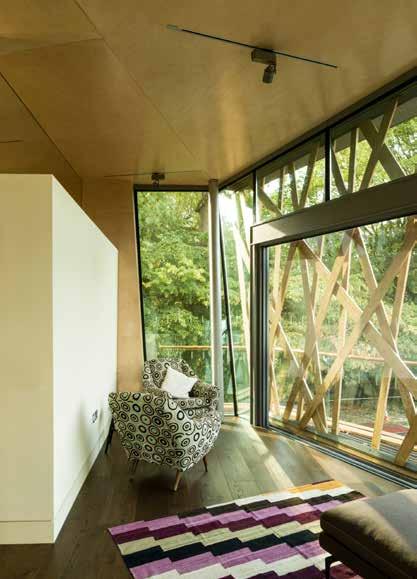
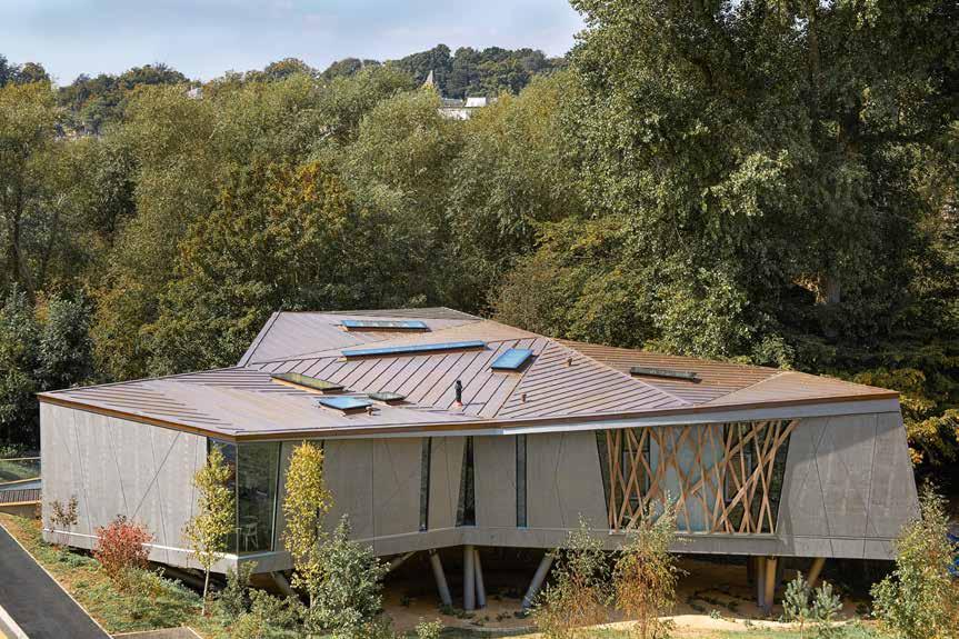
298 © WilkinsonEyre
LOCATION
Oxford, Oxfordshire
HEIGHT / STOREYS
26 ft (8 m) / 1 storey
CONSTRUCTION COST
Undisclosed
ARCHITECT
WilkinsonEyre
STRUCTURAL ENGINEER
Alan Baxter Integrated Design
TIMBER ENGINEER
Zublin Timber (formerly Finnforest Merk)
TIMBER CONTRACTOR
Zublin Timber (formerly Finnforest Merk)
TIMBER MANUFACTURER
Zublin Timber (formerly Finnforest Merk)
MAIN CONTRACTOR
Jacksons Contracting
TIMBER VOLUME
7,100 ft 3 (200 m 3)
TIMBER ASSEMBLY
5 weeks
OVERALL CONSTRUCTION
61 weeks
Healthcare (Public & Civic)
MAGGIE’S CENTRE
Maggie’s
Inspired by the concept of a tree house, this Maggie’s Centre floats amongst the trees adjacent to the oncology unit of the Churchill Hospital in Oxford.
13 feet above the ground in a small copse of mature trees, the building interacts with and embraces nature.
The angular geometry of the architectural form brings movement and life to the spaces, creating a building that feels warm, friendly and tranquil, rather than corporate or clinical. Consciously domestic in scale, the spaces within the centre are inviting, offering quiet places to retreat and reflect.
In keeping with the woodland setting the structure and cladding of the building is primarily timber. The building utilizes the strengths of the individual timber products to best serve the structural requirement. This combination of components enables the building to cantilever and float above the ground towards the tree canopies.
Raised from the ground on solid glulam columns, grouped in informal clusters to echo the surrounding woodland, the CLT panel floor creates a solid platform and a robust perimeter edge for the connection of level access balconies and the timber clad pedestrian bridge to the road. A folding three-dimensional LVL roof extends seamlessly throughout the building, sailing over the external balconies providing shelter and shading.
STRUCTURE TYPE
Pure Timber
EMBODIED CARBON WITHIN TIMBER*
-125 tons (-113 tonnes) CO 2 e
CLT FACT
Different timber products used in hybrid to their individual advantages
299
Floor Plan in Context
First
2014
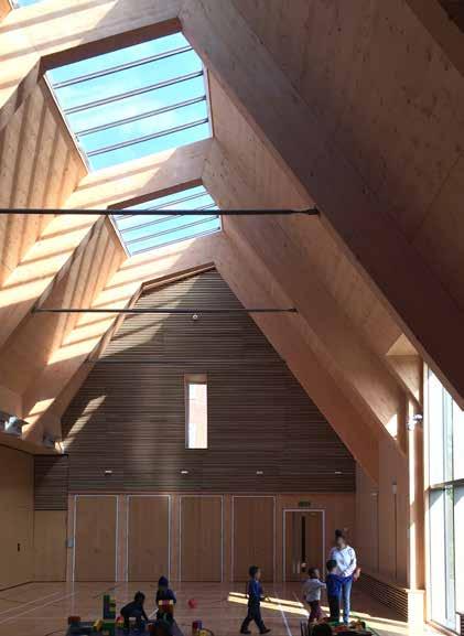
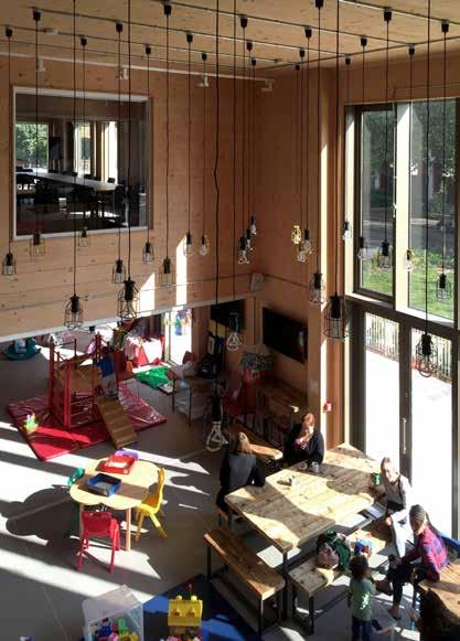
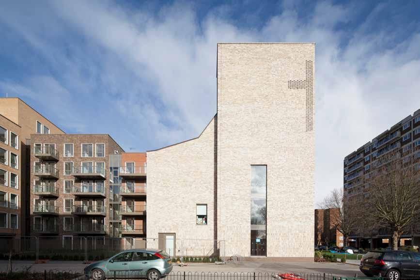
300
© Ben Luxmoore
© Matthew Lloyd Architects © Matthew Lloyd Architects
2015
Public & Civic
FRAMPTON PARK BAPTIST CHURCH
Frampton Park Baptist Church / Telford Homes
LOCATION
London Borough of Hackney
HEIGHT / STOREYS
67 ft (20.5 m) / 3 storeys
CONSTRUCTION COST
£2.5 million
ARCHITECT
Matthew Lloyd Architects
STRUCTURAL ENGINEER
RCA Structural Engineers / Price & Myers
TIMBER ENGINEER
Price & Myers
TIMBER CONTRACTOR
KLH UK
TIMBER MANUFACTURER
KLH Massivholz
MAIN CONTRACTOR
Telford Homes
TIMBER VOLUME
17,000 ft 3 (482 m 3)
TIMBER ASSEMBLY
6 weeks
OVERALL CONSTRUCTION
69 weeks
Frampton Park Baptist Church and apartments occupy the former site of a 1950s church. The new church, café and community facilities have been funded through the sale of the 47 apartments. The church and community facilities occupy a prominent position on Frampton Park Road, satisfying the need to be visible and welcoming. The entrance is marked by a soaring tower, a cross etched into the corner which is illuminated at night.
Sitting alongside the church entrance is a light-filled two-storey cafe with glazed openings onto the green space.
The café acts as the primary hub of the building and offers visual connections to much of the interior, including the youth club, project rooms, kitchen and offices. The worship space occupies the lofty, pitched-roof third storey. Daylight flows through skylights cut into the apex of the main roof and a smaller, asymmetrically appended side aisle with a raised stage. The aisle and hall can be subdivided into two separate rooms, while sports-pitch markings on the floor hint at the flexible use of this space.
The Church and community facilities are constructed in CLT. The CLT is left exposed internally providing warmth and a robust finish, of particular importance in a building used extensively by children and young people.
STRUCTURE TYPE
Hybrid
EMBODIED CARBON WITHIN TIMBER*
Developer’s previous experience with CLT led to its proposal -315 tons (-286 tonnes) CO 2 e
CLT FACT
301
Section
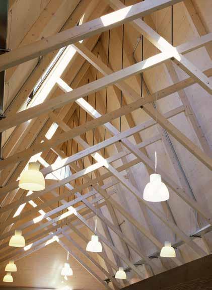
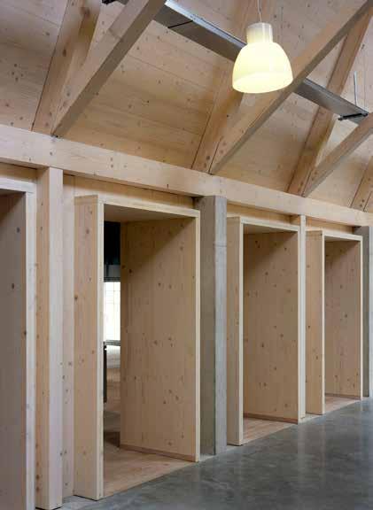

302
© Hélene Binet
2016
Public & Civic
CHATHAM COMMAND OF THE OCEANS
Chatham Historic Dockyard Trust
LOCATION
Chatham, Kent
39 ft (12 m) / 1 storey
CONSTRUCTION COST
£8 million
HEIGHT / STOREYS ARCHITECT
Baynes and Mitchell
STRUCTURAL ENGINEER
Price & Myers
TIMBER ENGINEER
Egoin
TIMBER CONTRACTOR
Egoin
TIMBER MANUFACTURER
Egoin
MAIN CONTRACTOR
WW Martin
TIMBER VOLUME
2,400 ft 3 (67 m 3)
TIMBER ASSEMBLY
2 weeks
Bringing a new lease of life to the historic buildings whilst retaining the character of the Chatham’s Historic Dockyard this new build element provides an entrance to the former workshops, repurposed as galleries telling the story of the expansion of the British Empire during the Age of Sail.
The cathedral like entrance hall completes a range of irregular sheds with its slender, pitched roof. A palette of black metal, blue limestone, boardmarked concrete and composite timber respond to the industrial language of the historic surroundings but also contrasts with the whitewashed sheds. Always intended to be timber, the new building’s entirely exposed structure is a modern interpretation of the surrounding timber framed buildings. CLT roof panels span between glulam scissor trusses supported on glulam tie beams and columns on a concrete base. The structural grid is twice that of the adjacent Wheelwrights Shop, allowing simple repetition of elements to create a rich spatial experience that echoes this nearby volume.
The 20 foot wide, 98 foot long gap between the Wheelwrights Shop and Grade I listed Mast House was 3D scanned to create a highly accurate computer model of the site. This combined with the accuracy of prefabrication of the timber structure ensured the success of this ‘infill’ project.
78 weeks
STRUCTURE TYPE
OVERALL CONSTRUCTION Pure Timber
EMBODIED CARBON WITHIN TIMBER*
-41 tons (-37 tonnes) CO 2 e
CLT FACT
Timber solution as a modern interpretation of surrounding structures
303
Section

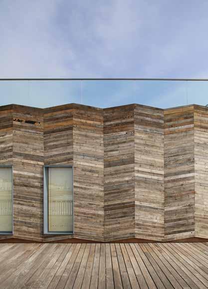
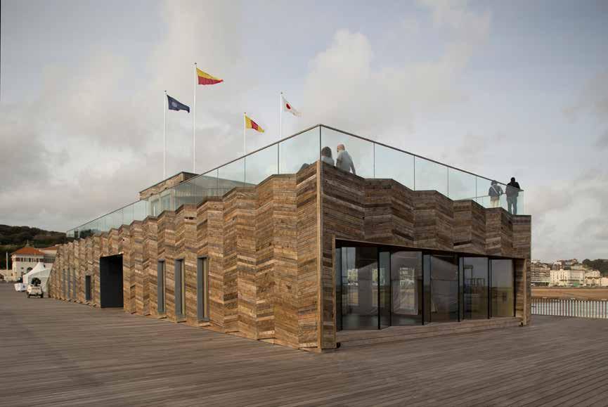
304
/
© Alex de Rijke
dRMM
Hastings & St Leonards, Sussex 2016
Public & Civic
VISITOR CENTRE, HASTINGS PIER
Hasings Pier Charity
LOCATION
HEIGHT / STOREYS
23 ft (6.9 m) / 1 storey
CONSTRUCTION COST
£1.2 million (+£700,000 support structure)
ARCHITECT
dRMM
STRUCTURAL ENGINEER
Ramboll
TIMBER ENGINEER
KLH UK
TIMBER CONTRACTOR
KLH UK
TIMBER MANUFACTURER
KLH Massivholz
MAIN CONTRACTOR
Hastings Pier Charity
TIMBER VOLUME
6,200 ft 3 (176 m 3)
TIMBER ASSEMBLY
With the original pier destroyed by fire in 2010, the redesign was an opportunity to redefine what a pier could be in 21st century. The visitor centre replaces the weakest, central section of the damaged pier and offers adaptable space for events, exhibitions and education, with an elevated panoramic lookout point.
A timber structural solution leant itself to this complex site where the physical constraints to construction were multiple: severe wind and rain, limited loadbearing capacity of the pier and access from the tidal sea.
The walls, stairs, lift and roof panels are CLT while glulam beams span the width of the centre and take loading for the roof terrace over the whole building.
CLT provided a relatively light alternative to steel and concrete which meant there could be a reduced thickness, weight and cost of the raft slab. This was important given that the building is supported on a steel structure projected out into the sea. CLT panels were easier to manoeuvre on the pier being lighter than other materials, a concern given the restrictions on loadings.
The first use of CLT in this kind of marine environment, the project demonstrates the material’s ability to deal with extremes of humidity levels, salt and UV.
48 weeks 3 weeks
OVERALL CONSTRUCTION
STRUCTURE TYPE
Pure Timber
EMBODIED CARBON WITHIN TIMBER*
-109 tons (-99 tonnes) CO 2 e
CLT FACT
First CLT structure to win the RIBA Stirling Prize (2017)
305
Section

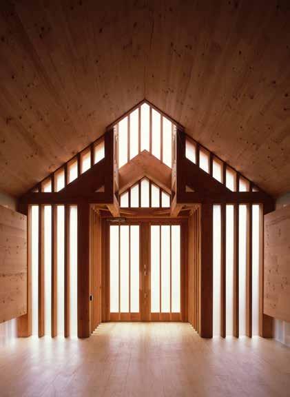
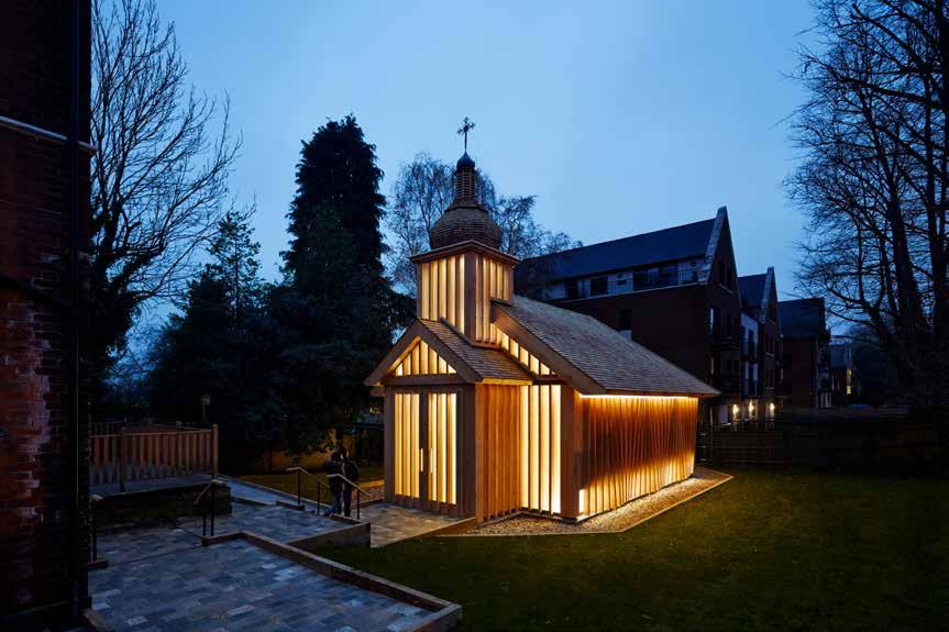
306
© Joakim Boren
© Hélene Binet
© Hélene Binet
London Borough of Barnet
HEIGHT / STOREYS
39 ft (12 m) / 1 storeys
CONSTRUCTION COST
ARCHITECT
Spheron Architects
STRUCTURAL ENGINEER
TIMBER ENGINEER
TIMBER CONTRACTOR
TIMBER MANUFACTURER
MAIN CONTRACTOR
Public & Civic
BELARUSIAN MEMORIAL CHAPEL
The Holy See of Rome co. Diocese of Westminster
The church in Woodside Park has been built for the Belarusian diaspora community in the UK, and is dedicated to the memory of victims of the 1986 Chernobyl nuclear disaster. Inspired by Belarus’ wooden church tradition the domed spire and timber shingle roof are common features of hundreds of traditional churches in Belarus.
A series of contemporary twists to the traditional form, such as the undulating timber frill of the flank wall enlivens the exterior. Natural light enters through low-level and concealed clerestory windows running the length of the chapel, and through tall frosted windows on the front elevation.
There are no additional finishes to the walls and structural frame, and the floor planks are made of Douglas Fir, all of which gives a distinctive smell to the interior. Externally, weather boards clad the CLT with vertical capping fins running along their joints. These fins are cut at slightly different angles to give an undulating profile, made up of only five simple variations without any use of computer generated algorithm.
The carefully coordinated, hidden location of the services, means that there is minimal impact on the beautiful clean lines of the interior structure and architecture.
TIMBER VOLUME
TIMBER ASSEMBLY
52 weeks 2 days
OVERALL CONSTRUCTION
STRUCTURE TYPE
Pure Timber Timberwright
EMBODIED CARBON WITHIN TIMBER*
CLT FACT
307
LOCATION
Ground Floor Plan
Light weight CLT avoided damage to the roots of adjacent protected trees Timberwright -32 tons (-29 tonnes) CO 2 e 1,900 ft 3 (53 m 3)
Egoin Timberwright Timberwright Undisclosed
2017
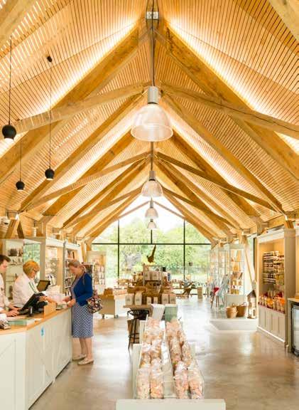
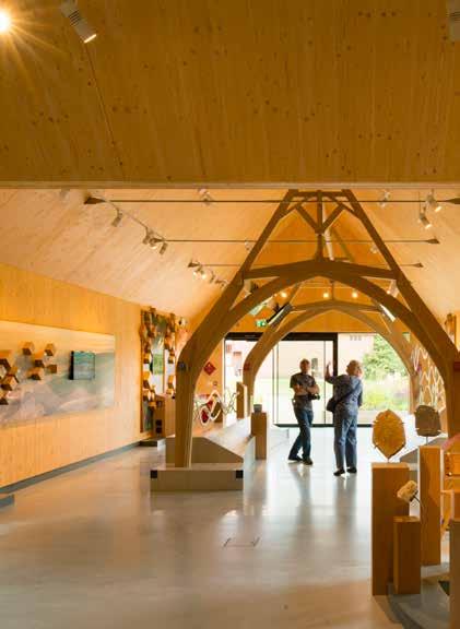
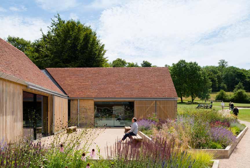
308
© Jim Stephenson
2017 Public & Civic
THE GATEWAY BUILDINGS
Weald and Downland Living Museum
LOCATION
Chichester, West Sussex
HEIGHT / STOREYS
24 ft (7.2 m) / 1 storeys
CONSTRUCTION COST
£2.9 million
ARCHITECT
ABIR Architects
STRUCTURAL ENGINEER
Cooper and Withycombe
TIMBER ENGINEER
KLH UK
TIMBER CONTRACTOR
KLH UK
TIMBER MANUFACTURER
KLH Massivholz
MAIN CONTRACTOR
A&F Pilbeam Construction
TIMBER VOLUME
12,700 ft 3 (359 m 3)
TIMBER ASSEMBLY
5 weeks
OVERALL CONSTRUCTION
60 weeks
The new visitor centre is designed around the idea of a farmstead village cluster and opens views and connections into the museum. Two new building clusters set either side of an entrance court provide a transitional threshold or ‘gateway’ between the new facilities (retail, café, community spaces) and the museum which consists of a collection of preserved historic vernacular buildings from South East England. To replicate any one style or period from the exhibits would have been innapropriate however a common theme of timber frame and materiality was established.
The new buildings combine traditional building materials with modern timber structures, detailing and construction techniques, sympathetic to and appropriate for their setting, they reflect and transcend some of the qualities of the collection. The timber frame references its historic counterparts whilst marrying the traditional with modern technology. Sizable sections of Green Oak connected through exposed stainless steel components express the materials and provide a clear understanding of the structural composition with flying structural members and kite ceilings.
The galleries and café spaces are constructed from CLT panels while externally 60,000 locally sourced hand-cleft timber shakes to the roofs are aligned with sweet chestnut cladding, Keymer Tiles and black-seamed zinc.
STRUCTURE TYPE
Pure Timber
EMBODIED CARBON WITHIN TIMBER*
-224 tons (-203 tonnes) CO 2 e Sections
CLT FACT
CLT used in modern interpretetion of historic timber structures
309
TIMELINE
310 2010 2005
p.277 The Termite Pavilion
p.269 MK40 Tower
p.271 Lumen Reform Church p.275 John Hope Gateway
p.273 The Garden Museum
p.279 Royal Shakespeare
p.119 Lauriston Primary School
p.113 West Buckland School
p.117 Tring Park School p.111 City of London Academy
p.115 The Open Academy
p.241 Woodland Trust HQ
p.237 The Office
p.239 Bedfont Lakes Pavilion
p.187 Watson House
p.175 Sunken House p.185 Strange House
p.183 Russell Street
p.179 Murray Grove
p.181 Hunsett Mill
p.189 Dune House
p.177 Cavendish Avenue
p.171 Carlisle Lane p.173 Fairmule House
p.121 Sandal Magna School
p.107 Kingsdale School p.123 Holy Trinity Primary School
p.109 Cranleigh School
p.105 Archway Early Years
311 2018 p.161 Alconbury Weald School p.165 SGS Berkeley Green p.157 Wynch Cottage p.287 Victoria Leisure Centre p.283 Tower of Love p.285 The Hive p.289 Regents Park Theatre p.295 Olympic Park Lodge p.299 Maggie’s Centre p.305 Hastings Pier p.297 Glowing Orchard p.301 Frampton Park Church p.281 Dyson Neonatal p.291 Youth Leisure Zone p.293 Ditchling Museum p.303 Chatham Command p.309 Gateway Buildings p.307 Belarusian Chapel p.145 Alfriston School Pool p.129 Hereford College of Arts p.131 Hayes Primary School p.141 William Perkin School p.143 Ark Brunel Primary Academy p.127 Waingels College p.135 The Lee Centre p.209 142 Bermondsey St. p.227 Bacton Low Rise p.263 Wildernesse p.251 Sky Health & Fitness Centre p.257 De Beauvoir p.249 Crosslam Workshops p.255 Christies Care Office p.245 Architecture Archive p.243 Alex Monroe Studio p.195 Woodblock House p.193 Whitmore Road p.205 Wenlock Cross p.211 Trafalgar Place p.221 Hurdle House p.259 Lower James Street p.197 Sussex House p.215 St Clare’s College p.225 UEA Blackdale p.261 Vitsoe HQ p.265 NAIC p.201 Nurses Cottage
Mazarin House p.247 Sky Believe in Better
Lansdowne Drive
Kingsgate House
Bridport House
Carmarthen House
Dalston Works
Curtain Place p.223 Cowan Court p.213 Cobalt Place
Barretts Grove p.219 Woodberry Down p.233 Pitfield Street
Passmores Academy
Oculus Building
Mossbourne
Mayfield School p.159 Centre for Chemistry p.137 Ickburgh School p.133 Hilden Grange School
Graveney Sixth Form p.167 Ely Boathouse
Essex Business School
Davenies Boys School
Arcadia Nursery 2015
p.199
p.217
p.203
p.191
p.231
p.229
p.253
p.207
p.125
p.163
p.149
p.147
p.151
p.153
p.155
p.139
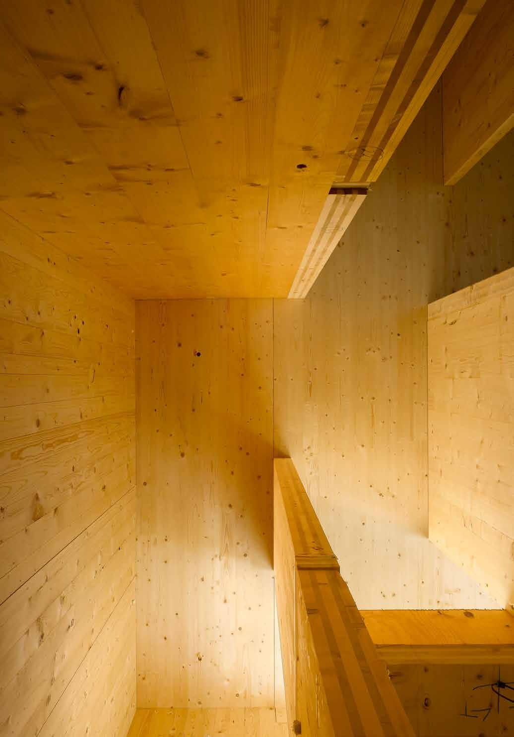
CONCLUSION
The one hundred projects featured in this book were selected from over 500 completed CLT projects in the UK. The scale and variety of buildings in CLT demonstrates that the era of engineered timber is now upon us.
We often refer to human civilisations by the principal materials they employ, such as the Bronze Age, Iron Age etc. In this vein, the 20th century can be very much called the Concrete Age and it seems very likely that the 21st century will be the Timber Age.
The adoption of engineered timber technology in construction mirrors the emergence of concrete a hundred years ago. An ancient building material, brought into modern use through enhanced engineering, the first practitioners of which chose to mimic the forms from the existing building technologies. As the use of this new material became more widespread and the capabilities became better understood, a new architecture emerged expanding the engineering possibilities concrete offered. Ultimately, a new urbanism developed, that had its impact on most cities of the world.
The hundred projects featured in this book already chart an emergence of a new architecture that owes its form to the possibilities offered by engineered timber. With the technology still in its infancy, one can only speculate as to the new forms that will emerge as the use of CLT becomes mainstream. The tectonic expression of mass timber is still developing. New technologies demand new forms. For centuries, material innovation has been a means with which to revitalize the traditions of architecture.
As the greater use of timber in construction mirrors a changing attitude towards our planet and our living environment, the new urbanism of timber should offer us new ways of working and living together.
313
Image: Murray Grove, Waugh Thistleton Architects © Will Pryce
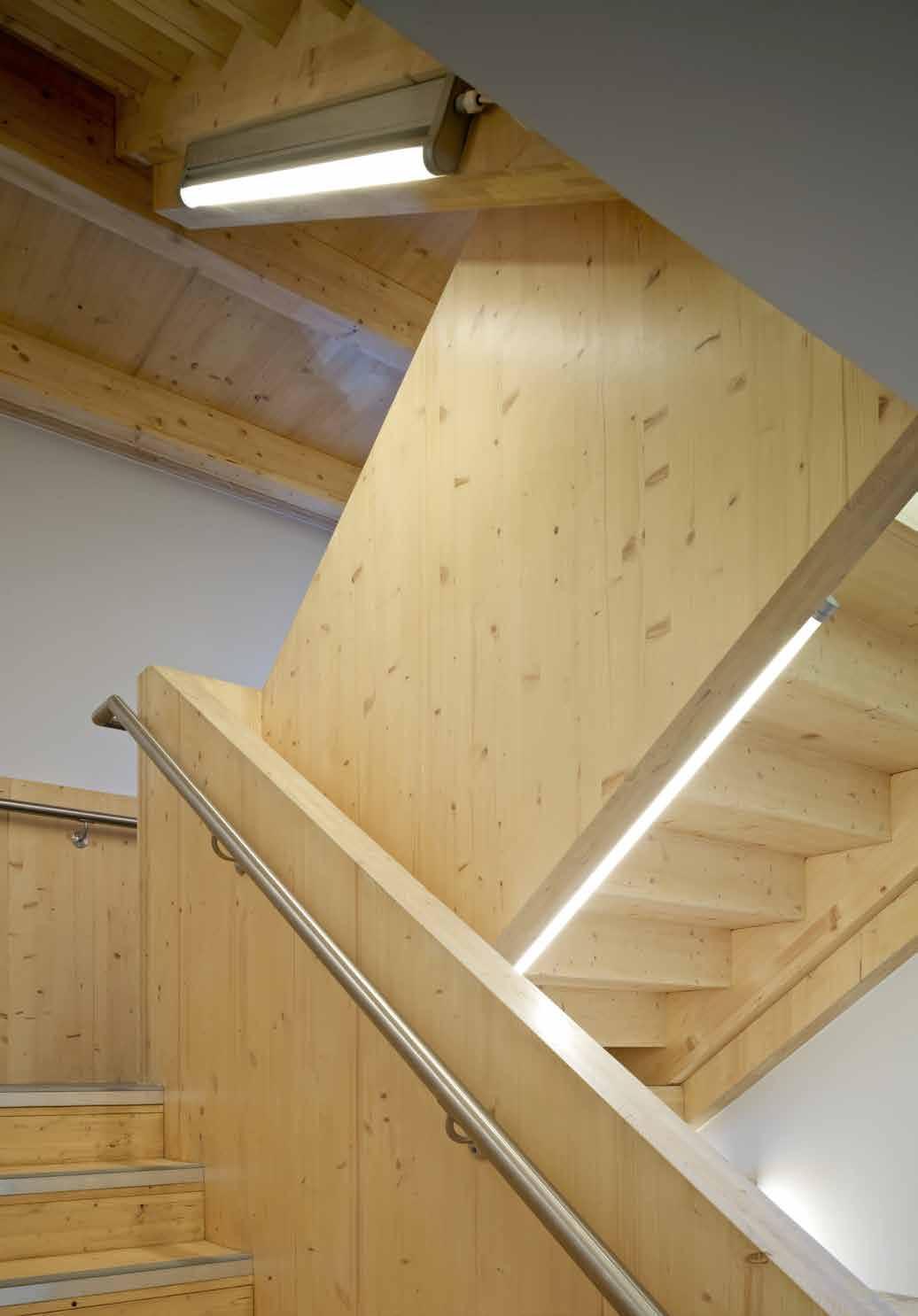
Air Tightness Line - a notional line completely enclosing a building defining the point at which airtightness measures are employed.
BIM - Building Information Modelling is a digital representation of the physical and functional characteristics of a building.
BREEAM - Building Research Establishment Environmental Assessment Method, UK certification program.
Carbon Cycle - processes such as photosynthesis, decomposition, and respiration, by which carbon, as a component of various compounds, cycles between its major reservoirs.
Carbon Reservoir / Sink - eg. the atmosphere, oceans, and living organisms which absorb and store large amounts of carbon dioxide from the earth's atmosphere.
Cascade principle - a method of increasing the efficient use of a raw material by giving priority to higher value uses that enables reuse and recycling and promotes energy use only when other options are starting to run out.
CLT - Cross Laminated Timber
CML - Council for Mortgage Lenders
CNC - Computerized Numerical Control, drilling and machining tool controlled via digital input.
Co-ordinated Drawings - a stage of building design where the structure, finishes and services are completely integrated.
Collaborative Design - the close working and partnership of all consultants and contractors in the design and construction of a building, often facilitated by BIM.
Critical path - The longest sequence of activities in a project plan which must be completed on time for the project to complete on due date.
De-lamination - for CLT, where glued layers separate, either through the action of moisture or fire.
Design Freeze - at key stages of a project the design is signed off and is fixed from that point.
Dew Point - the temperature at which water vapor in the air condenses into liquid water.
EFA - Education Funding Agency Image: Russell Street, 5th Studio
315
GLOSSARY
© Tim Soar
Embodied Carbon - carbon dioxide emitted during the manufacture, transport and construction of a building materials, together with end of life emissions.
Encapsulation - the approach of protecting building elements by the application of fire lining.
End grain - the grain of wood seen when it is cut across the growth rings.
Engineered Timber/Mass Timber - a generic name incorporating CLT, glulam, LVL and others.
EPD - Environmental Product Declaration
Finger Jointed - in CLT manufacture, method by which boards are joined end to end by cutting an extended sawtooth to both boards and then gluing.
Fire Integrity - the duration for which a building element or system can withstand a standard fire resistance test.
Flanking Sound - sound transmitted between spaces indirectly, going over or around, rather than directly through a floor or wall.
Follow-on-trades - refers to the activities that follow erection of a structural frame such as running services or lining out.
FSC - Forest Stewardship Council
Operational Carbon - carbon dioxide emitted during the life of a building, through heating, cooling, lighting, and power.
Glulam - Glue Laminated Timber
Heat degradation - deterioration of a material as a result of excessive heat.
Hydraulic press - more common method of CLT production, utilizing hydraulic rams for the gluing of the timber laminas.
Impact Sound - sound arising from the impact of an object on a building element, such as footsteps.
Just-in-time delivery - strategy of receiving materials on site only as they are required, reducing requirements for storage.
LCA - Life Cycle Assessment
Lead-in Period - the time required between placing an order for an item and delivery to site.
LEED - Leadership in Energy and Environmental Design, US certification system run by the U.S. Green Building Council.
Listed Building - one that is deemed of historic interest and is legally protected. Special permission from the local planning authority is required for any work to be carried out. They range from Grade II: special interest, Grade II* ("grade two star"): more than special interest and Grade I: exceptional interest.
LVL - Laminated Veneer Lumber
Mitigated Carbon - savings in carbon dioxide emissions from active measures aimed at reduction or prevention.
Moisture content - ratio of the mass of water in a material to the mass of solid.
316
MUF - Melamine urea formaldehyde resin is an adhesive thermosetting resin.
NHBC - National House Building Council, provides construction inspection services and 10 year warranties to UK housing developments.
NIA - net internal area.
PEFC - Program for the Endorsement of Forest Certification
Phase change material - a substance capable of storing and releasing large amounts of energy through melting and solidifying at a certain temperature.
Progressive Collapse - also known as Disproportionate Collapse, refers to when a primary structural element fails that results in the failure of adjoining structural elements, which in turn causes further structural failure.
PUR - polyurethane is type of hot melt glue that polymerizes when applied so that they form much stronger bonds than traditional hot melts.
Sequestered Carbon - the process of capture and the long-term storage of atmospheric carbon dioxide to mitigate global warming.
Service use class - a rating of 1 to 5 that identifies the recommended exposure of timber to water in use based on the characteristics of the timber itself and treatments applied.
SIPs - Structural insulated panels are a high performance building system for residential and light commercial construction.
Smoke modelling - method of simulating the behavior and temperature of smoke in the event of a fire.
Strength to weight ratio - a material's strength (force per unit area at failure) divided by its density.
Thermal Conductivity - the rate at which heat passes through a specified material, expressed as the amount of heat that flows per unit time through a unit area with a temperature gradient of one degree per unit distance.
Thermal storage capacity / Thermal Mass - the ability of a material to absorb and store heat energy. Dense materials such as brick and concrete have a high thermal mass, whereas timber has a low thermal mass.
Timber frame - traditional construction method creating framed structures from solid timber members.
UN - United Nations
Vacuum press - an alternative method of producing CLT panels by evacuating the air under a rubber based sheet.
Vapor Control Layer - a vapor tight membrane installed to a roof or wall on the inside face.
Vapor Permeable Membrane - restricts the amount of water that can pass through but does not block it, helping reduce the build-up of condensation within a structural element.
VOC - Volatile Organic Compound
317
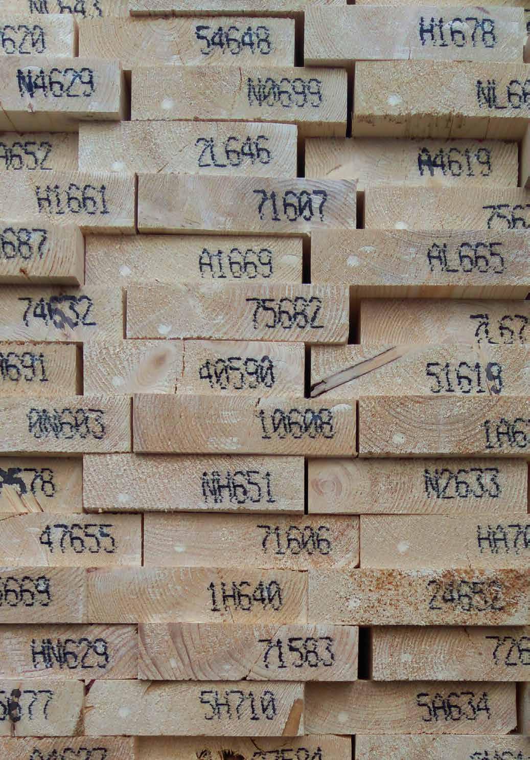
METHODOLOGY
* EMBODIED CARBON METHODOLOGY
The embodied carbon (cradle to site) figures for each case study were calculated via the below methodology, using the sources listed. The timber volumes and delivery numbers were sourced from the architects or timber suppliers/manufacturers and the distances between the factories and sites calculated on https://www.distancecalculator.net as via road transport.
Sequestered carbon and CLT production embodied carbon:
Input = Timber Volume (m 3) = X
A = Sequestered carbon = X x -790kg CO 2 (ASBP)
B = Processing embodied carbon = X x 190kg CO 2 (ASBP)
A + B = Cradle-to-Gate embodied carbon = X x -600kg CO 2 (ASBP) = -600X kg CO 2
Transportation of CLT:
Input = Number of Deliveries = Y
Average Distance = Zkm
Fuel Consumption = 0.44 L/km (DEFRA)
Carbon impact of fuel = 2.63kg CO 2/L (Department of the Environment, Food and Rural Affairs, 2007)
0.44Z x 2.63 = 1.157Z kg CO 2 per delivery
Y x 1.157Z kg CO 2 = 1.157YZ kg CO 2
Overall Embodied Carbon:
-600X kg CO 2 + 1.157YZ kg CO 2 = Embodied Carbon (cradle-to-site)
Image: Sawmill, Austria © Waugh Thistleton Architects
319
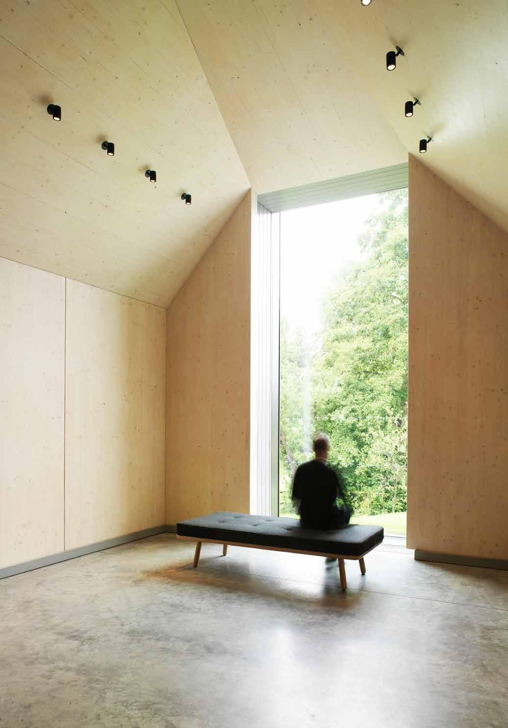
BIBLIOGRAPHY
While there is already a considerable amount of literature on cross-laminated timber, the range of references is growing constantly. A regularly updated and comprehensive list of books, press articles and technical guidance can be found at www.wt-x.net/publications.
The list below is a selection of the principal reference documents on CLT and building in mass timber.
Michael Green, The Case for Tall Wood Buildings , Blurb, 2018
Sylvian Gagnon and Ciprian Pirvu (ed.), CLT handbook: cross-laminated timber , FP Innovations and Binational Softwood Lumber Council,2011
Ireneusz Bejtka, Cross (CLT) and diagonal (DLT) laminated timber as innovative material for beam elements , KIT Scientific Publishing, 2011
Andy Sutton and Daniel Black, Cross-Laminated Timber, An introduction to low-impact building materials , BRE Press, 2011
Various, Cross-laminated timber, Design and Performance , Exova BM TRADA, 2017
Virginia McLeod, Detail in Contemporary Timber Architectur e, Laurence King Publishing, 2010
Johannes Hummel, Displacement-based seismic design for multistorey cross laminated timber buildings , Kassel University Press, 2017
Simone Jeska, Emergent Timber Technologies - Materials, Structures, Engineering Projects , Birkhauser, 2015
Petter Bergerud, Experimental Wooden Structures , Bergen Academy of Art and Design, 2015
Image: Ditchling Museum of Art and Craft, Adam Richards Architects © Brotherton Lock
321
Jim Birkemeier, Home Made Timer Panels - How We Make Cross Laminated Timber Panels From Our Trees at Timbergreen Farm , Amazon, 2107
Peter Wilson, The Modern Timber House in the UK , Wood for Good, 2018
Robert Hairstans, Mass Timber - an Introduction to Solid Laminate Timber Systems , Arcamedia, 2018
Susan Jones, Mass Timber: Design and Research , Oro Editions, 2018
Lars Mytting, Norwegian Wood - Chopping, Stacking and Drying Wood the Scandinavian Way , Maclehose Press, 2015
Andrew Waugh, Karl Heinz Weiss, Matthew Wells, A Process Revealed / Auf Dem Holzweg , Murray & Sorrell FUEL, 2009
Joseph Mayo, Solid Wood: Case Studies in Mass Timber Architecture, Technology and Design , Routledge ,2015
Jack Porteous and Andy Kermani, Structural Timber Design to Eurocode 5 , Wiley-Blackwell, 2nd Edition, 2013
James Norman, Structural timber elements, a pre-scheme guide , Exova BM TRADA, 2016
Andrew Bernheimer (ed.), Timber in the City: Design and Construction in Mass Timber , Oro Editions ,2015
Michael Dickson, Sustainable Timber Design , Routledge ,2015
Josef Kolb, Systems in Timber Engineering , Birkhäuser, 2018
Michael Green, Jim Taggart, Tall Wood Buildings - Design Construction and Performance , Birkhäuser, 2017
Ulrich Daniel, Turning Point in Timber Construction - A New Economy , Birkhäuser, 2016
United Nations, World Urbanization Prospects , The 2014 Revision, Highlights (New York, United Nations, 2014)
322
323
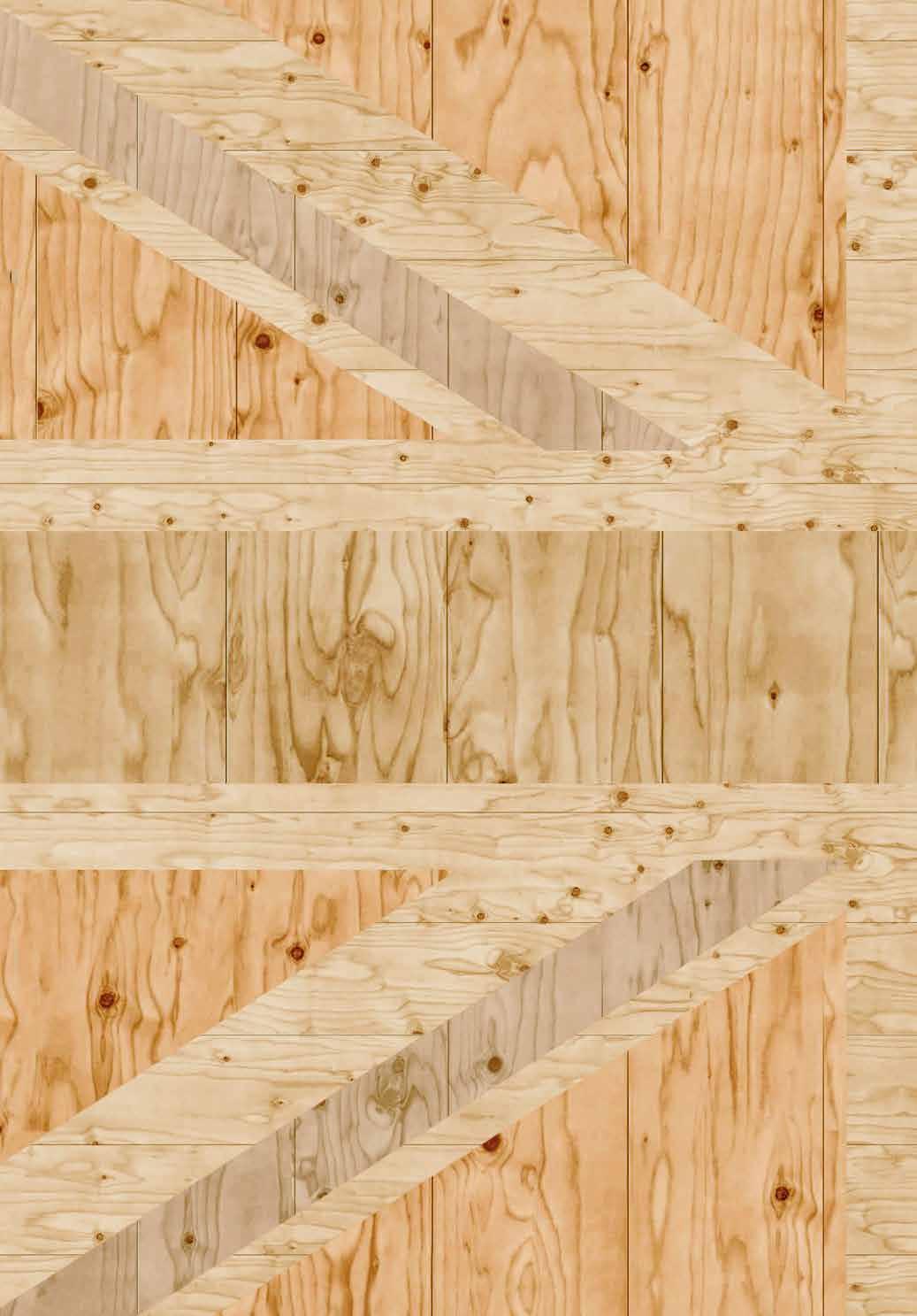
Over the last 15 years the UK has experienced a quiet revolution in construction. Since the modest efforts of the first small buildings in the early 2000s a blossoming array of CLT projects has emerged across a range of building types and scales. In 2017, three out of the five buildings nominated for the Stirling Prize, the UK’s top architecture award, were constructed from CLT. Engineered timber buildings are now firmly part of our construction landscape.
This book presents the case for using engineered timber with one hundered studies encompassing a wide range of scales, styles and types.
Also included is a compendium outlining the benefits of CLT along with the considerations for designing and building in this revolutionary material.