TIMBER TYPOLOGIES Waugh Thistleton Architects Published by Timber Development UK Understanding options for timber construction
1
Editor Jane Collier Waugh Thistleton Architects
Waugh Thistleton Architects Illustrations Waugh Thistleton Architects Contributors
Nick Boulton, Head of Technical & Trade Policy, TDUK
Matt Caldwell, Associate Structural Engineer, Buro Happold
Sam Hart, Head of MMC, BE-ST
Charlie Law, Sustainability Director, TDUK
Mark Milne, Impact Manager, BE-ST
Louise Rogers, Impact Manager, BE-ST
Text ©
All rights reserved No part of this publication may be reproduced without the written permission of the publisher or the copyright owner. Printed in the UK
Published 2023
Waugh Thistleton Architects
Authors
TIMBER TYPOLOGIES
Understanding options for timber construction
1 TIMBER BENEFITS 9 1.1 Carbon in construction 10 1.2 Why build in timber? 12 1.3 Forestry 14 1.4 Off-site construction 16 1.5 Health and well-being 18 2 TIMBER COMPONENTS 21 2.1 Overview 22 2.2 Lightweight timber frame components 24 2.3 Glued laminated timber 26 2.4 Laminated veneer lumber 28 2.5 Cross-laminated timber 30 3 TIMBER SYSTEMS 33 3.1 Overview 34 3.2 Lightweight timber frame 36 3.3 Volumetric modular 40 3.4 Panellised mass timber 44 3.5 Post and beam 48 3.6 Hybrid systems 52
CONTENTS
4 APPLICATION 55 4.1 Overview 56 4.2 Low-rise residential 58 4.3 Mid-rise residential 60 4.4 Commercial 62 5 OTHER CONSIDERATIONS 65 5.1 Fire 66 5.2 Moisture 68 5.3 Acoustics 70 6 FURTHER READING 73
PREFACE
Timber is the single most important material when it comes to decarbonising construction. But if timber is to realise its potential, we need to be specific about what we mean when we say timber.
There is a lot of misconception and misinformation out there – and even within the timber supply chain. We might think we know exactly what we mean when we refer to ‘timber frame’, ‘mass timber’ or ‘stick build’. But others might have slightly different definitions. We can’t make progress if designers, clients, specifiers and engineers are talking at cross-purposes. The industry needs better information about the variety of timber systems and options which exist. That starts with using the right language to describe the system or the building approach. And that’s why we’ve written this book.
It is intended as a primer – a ‘beginner’s guide’ – to all the different timber solutions. We hope that developers, policy makers, designers and stakeholders will use it to inform their discussions. It will help them understand the choices available to them - so they make the right decisions and deliver the best buildings possible.
Timber Typologies is the first in a trio of essential books. It will be accompanied by Timber Policy, which outlines different ways countries can promote timber use, and Timber LCA, demystifying lifetime carbon analysis for timber buildings.
Lowering the carbon footprint of our built environment is no longer a choice it is a necessity if we want to maintain a habitable living environment. Timber can achieve this in many varied and beautiful ways. This book helps to show people how.
Visit timberdevelopment.uk to learn more about building with timber.
1
TIMBER BENEFITS
1.1 CARBON IN CONSTRUCTION
In 2018 the IPCC stated that the world needs to reach net zero carbon emissions by 2050 if it is to meet the Paris Agreement target of limiting global warming to 1.5°C. This deadline was part of the Glasgow Climate Pact agreed at COP26 in 2021. The Pact stresses that “limiting global warming to 1.5°C requires rapid, deep and sustained reductions in global greenhouse gas emissions.”
According to the International Energy Agency (IEA), the built environment generates 40% of annual global CO 2e emissions. Building operations are responsible for 27%, while embodied carbon - emissions generated through building materials and construction processes - is responsible for the remaining 13%.
Embodied carbon emissions
The reduction of embodied carbon emissions is key to meeting statutory targets on carbon reduction within the construction industry. Until recently, sustainable building guidance has tended to focus on reducing operational energy - carbon emissions associated with heating, hot water, cooling, ventilation, and lighting systems.
Increasingly, buildings are becoming more energy efficient, with better thermal properties. This improvement, coupled with the ongoing decarbonisation of the national electriciy grid, means embodied carbon is responsible for a bigger share of a building’s carbon footprint.
It could represent up to 70% of the whole life carbon emissions of a new building (LETI, 2020).
Timber and embodied carbon reduction
Circularity and the use of bio-based materials are two key strategies to reduce embodied carbon in the construction sector. The use of wood in buildings offers four primary benefits:
1. Carbon is sequestered as trees grow.
2. Timber replaces high-carbon building materials such as concrete and steel - mitigating their associated emissions.
3. By reducing the weight of the superstructure and therefore the size of foundations, less material is used and fewer related emissions released. By using timber, embodied carbon could be reduced by a third.
4. The timber in the structure also acts as a ‘carbon store’, locking the carbon away for the life of the structure, which could be hundreds of years.
A decarbonising construction industry
Legislative and advisory bodies such as the GLA, LETI, RICS and RIBA have set benchmarks and targets to reduce embodied carbon in construction and these are increasingly becoming incorporated into planning guidance for new developments.
Lowering the embodied carbon of construction will require a fundamental shift: to building with sustainable, low embodied carbon materials. Focussing on building elements such as the structure, which typically accounts for about 50% of a building’s embodied carbon will be key.
Within this context, and in light of the climate challenge we face, timber construction systems offer a familiar, viable, and scalable solution for decarbonising the construction industry.
10
1.2
WHY BUILD IN TIMBER?
Timber and MMC
Timber is acknowledged as an ideal material for modern methods of construction (MMC)as defined in ‘Modernise or Die’, a report by the Construction Leadership Council (2016), and categorised in the UK Government’s ‘MMC Definition Framework’.
The world is in the midst of a housing crisis, with an overall mass migration to cities. The UN predicts that 66% of the world’s population will be resident in urban areas by 2050. In order to deal with this flow of people, we need to address the way new buildings are delivered in our cities. Higher density, lower carbon, mid-to-high-rise developments provide a solution. If urban structures continue to be predominately built in steel and concrete, the climate change implications are considerable. The production and use of cement is responsible for approximately 8% of the world’s total CO2 e emissions (Chatham House International Think Tank), a figure that will increase if urban construction trends continue.
At the same time, a gradual decline in construction productivity over the past 50 years presents further challenges in meeting the growing demand for homes. Whereas cement and steel production uses finite materials, timber from managed forests is replenishable and sustainable and stores carbon within its fabric. Building in timber rather than with concrete and steel could save an average of 40 tonnes of CO 2 per home (Berners-Lee, 2010).
The rise of mass timber
Traditionally, timber has not been used for high density buildings. But the development of mass timber products (such as CLT and glulam) has enabled timber to compete structurally at scale. Highly engineered products that overcome many of the limitations associated with lightweight timber frame have made wood construction a viable alternative to traditional construction methods.
However, different timber construction methods often get lumped together under the phrase “timber frame”. In reality, there is a range of products and systems, including lightweight timber frame, mass timber and hybrid solutions, which all have their own advantages.
Explaining the different timber systems
This publication is designed to highlight the benefits of each system, the differences between them and their suitability for delivering housing and commercial office space. Although the application of timber systems to other sectors, including education, health and industrial, falls outside of the scope of this document, these markets also provide increasingly fertile ground for timber construction.
12
1.3 FORESTRY
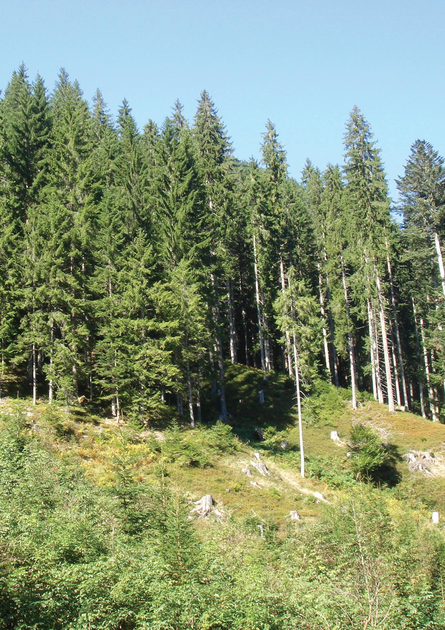
Currently, one third of the Earth’s land area is covered by forest, which equates to around 4 billion hectares. An individual forest’s characteristics and make-up are determined by the latitudinal location and climate. The three distinct types of forest include: boreal, temperate further south, and tropical and subtropical near to the equator.
In order to keep global warming within safe limits, the world needs to develop effective strategies for atmospheric carbon dioxide removal (CDR). Most climate scientists recognise that the only current viable method of CDR at scale is to grow more sustainably managed forests.
How can forestry help CDR?
Trees absorb CO 2 rapidly during growth with the rate declining as the tree reaches maturity. At that point the amount of CO 2 absorbed through photosynthesis is equal to that lost through respiration and decay.
In order to reliably and efficiently use trees and forestry for CDR, a sustainable and long-term use for the timber is required - so that mature trees are felled and new trees are planted. This maintains the overall carbon pool of the forest and yields new material.
Harvesting timber from sustainably managed forests, where replanting maintains or increases timber numbers, increases their capacity as a carbon sink.
Timber buildings as carbon stores
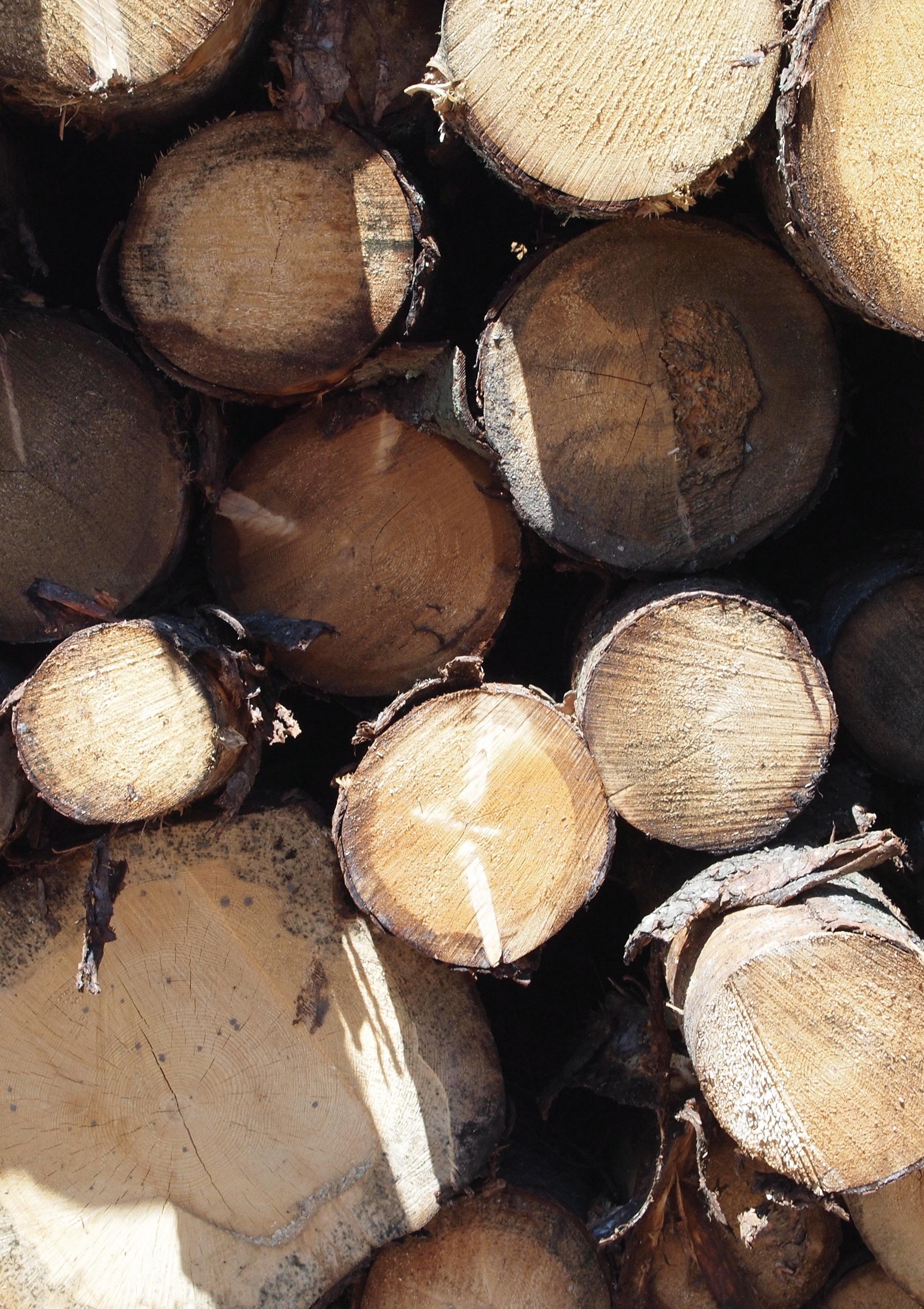
The products made from the felled timber store carbon within their fabric while they are in use.
So using timber as a structural material not only reduces the direct emissions related to construction, reducing the need for carbon intensive materials such as steel and concrete, but the buildings themselves become a new carbon store, with carbon sequestered within their structures.
Ensuring responsible forestry
Certification bodies regulating the legal harvest of timber include The Forest Stewardship Council (FSC) and Programme for the Endorsement of Forest Certification (PEFC).
This third-party certification confirms that forests are managed in a responsible and sustainable way, ensuring diversity, biodiversity, supply, and good conditions for workers.
14
1.4 OFF-SITE CONSTRUCTION
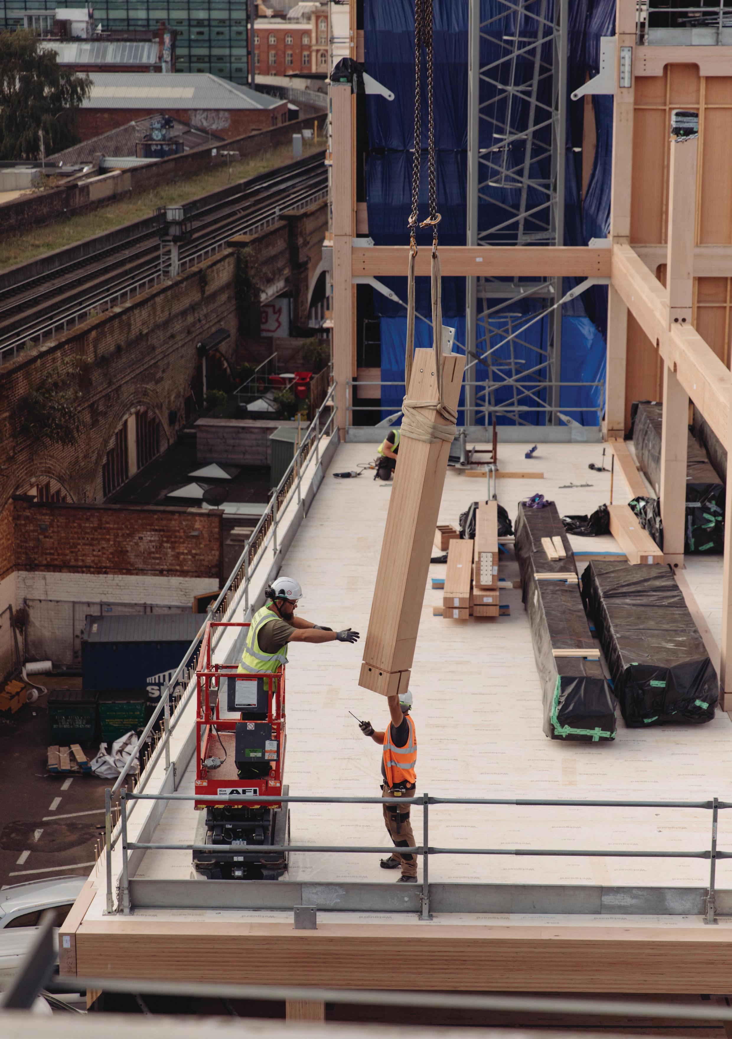
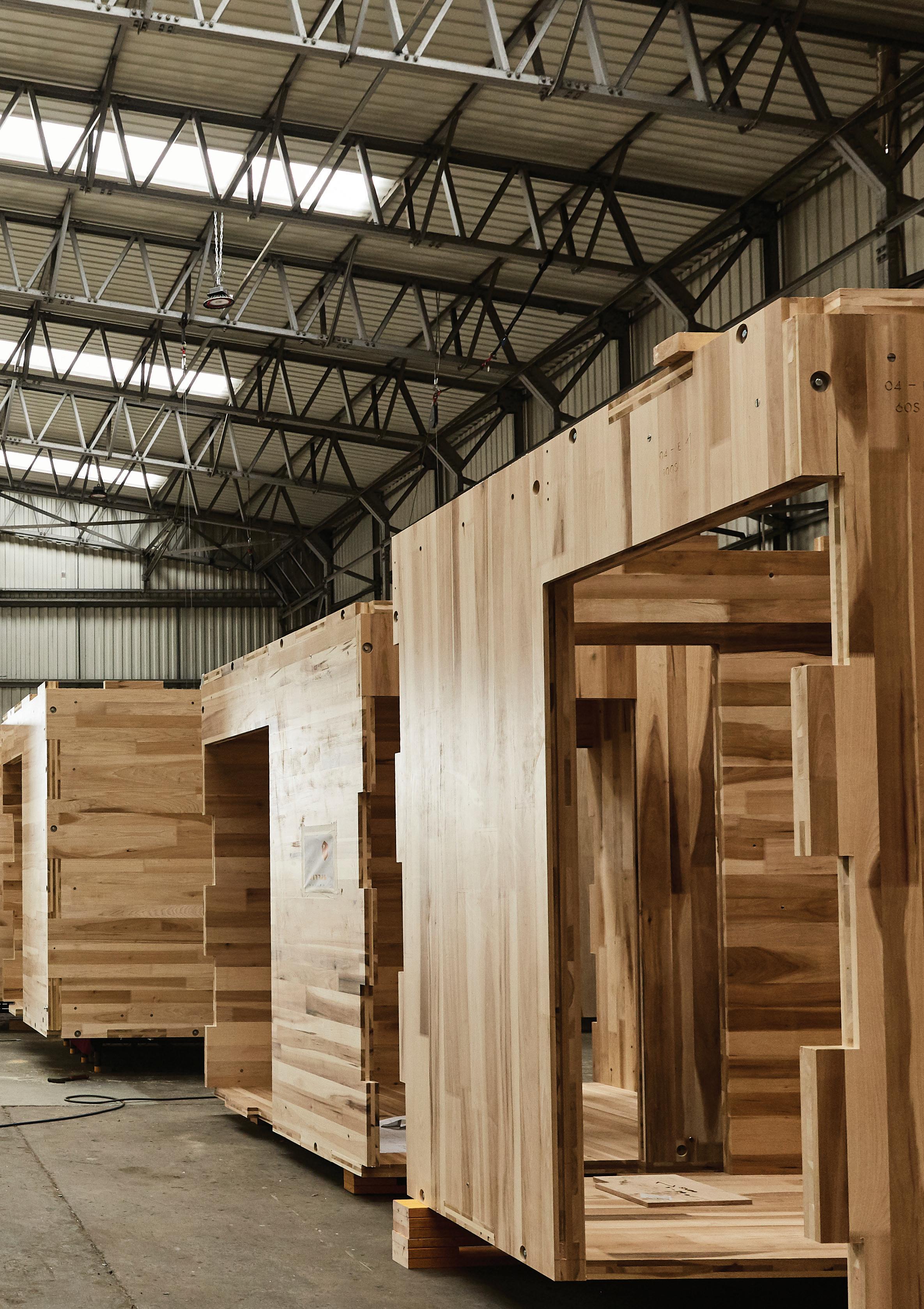
Off-site construction draws on the efficient production and quality assurance processes developed by ship, aircraft and car manufacturers. It is able to improve on many inefficiencies associated with traditional construction methods. Innovations in manufacturing and assembly have enabled timber components, sections and even entire volumetric units to be fully fabricated off-site.
All timber construction systems detailed in this guide are defined within the Modern Methods of Construction (MMC) Definition Framework:
1. Pre-manufacturing (3D primary systems)
2. Pre-manufacturing (2D primary systems)
3. Pre-manufacturing components (non-systemised primary structure)
4. Additive manufacturing (3D printing, structural and nonstructural)
5. Pre-manufacturing (non structural assemblies and sub-assemblies)
6. Traditional building product led site labour reduction/productivity improvements
7. Site process led site labour reduction/ productivity/assurance improvements
Benefits of off-site construction
The many benefits associated with off-site construction include:
– shorter on-site build times
– increased accuracy and quality
– reduced waste
– improved site working conditions
Time on-site can be significantly reduced, depending on the level of prefabrication, with the potential for turnkey homes to be assembled within a day. The manufacturing and assembly times of elements produced in the factory are also reduced compared to a traditional on-site build.
With factory-led manufacturing, it is much easier to maintain the quality, standardisation and accuracy of components. Off-site constructed timber elements are produced by several manufacturers across Europe, ensuring that procurement is competitive for clients.
BIM and the digital twin
Information generated by Building Information Modelling (BIM) allows the factory to order products ‘just in time’ with the benefit of a consistent material and labour supply chain. Digital twins can provide a long-term record of components within the building, streamlining repair and maintenance.
How off-site benefits onsite
The onsite experience is also improved when compared to traditional construction. The controlled factory environment means that short days and bad weather do not interfere with production.
The labour requirements to construct a prefabricated system and the health and safety considerations onsite can be simplified, as fewer trades and materials are present simultaneously.
The completion of entire solid walls concurrently with floors and roofs means the building becomes watertight more quickly, providing a dry working environment.
16
1.5 HEALTH AND WELL-BEING
In a post pandemic world, environments for people to work and live that promote health and well-being has never been more important to developers and building users. A healthy environment that prioritises daylight, space, ventilation, comfort, acoustics, and biophilia can boost productivity and levels of user satisfaction within residential and office spaces.
In 2015, Planet Ark Environmental Foundation, an Australian not-for-profit environmental organisation, published a review of studies analysing the health and well-being benefits of wooden interiors in homes, businesses, schools and hospitals.
“We know that workers are less stressed and more productive, students learn better, patients heal faster, and people are generally happier and calmer in indoor areas which contain wooden elements,” states David Rowlinson, Make It Wood Programme Manager at Planet Ark.
The review identified that the increased use of wood has measurable physiological and psychological health benefits. Exposing timber in interiors could lead to reducing the blood pressure, heart rate and stress levels of inhabitants.
Studies also show that living and working in a wooden interior can improve a person’s emotional state.
The review identified studies that show that the presence of wood in offices can dramatically improve a visitor’s response to the company by conveying the impression of innovation, sustainability, energy and comfort.
Companies with timber interiors report higher levels of staff retention, greater levels of productivity and lower levels of sickness.
The use of wood has a beneficial effect on air quality through moderating levels of humidity. The timber absorbs moisture in humid conditions and releases moisture in dry conditions, through a process known as Hygric Buffering.
Wood does not become electrically charged, which inhibits the raising of dust, reducing allergens and increasing the quality of life for those suffering with respiratory problems.
Timber surfaces and massive timber panels have an acoustic benefit, absorbing sound and so improving comfort, particularly in more public environments (see Section 5.3: Acoustics).
18
2 TIMBER
COMPONENTS
2.1 OVERVIEW
The term timber is used to refer to wood at any stage after the tree has been felled. This includes the raw material and the processed material. Timber used in construction can be divided into standardised two categories, lightweight timber frame and mass timber systems. These have different performance capabilities that make them suitable for different applications.
What are lightweight timber frame components?
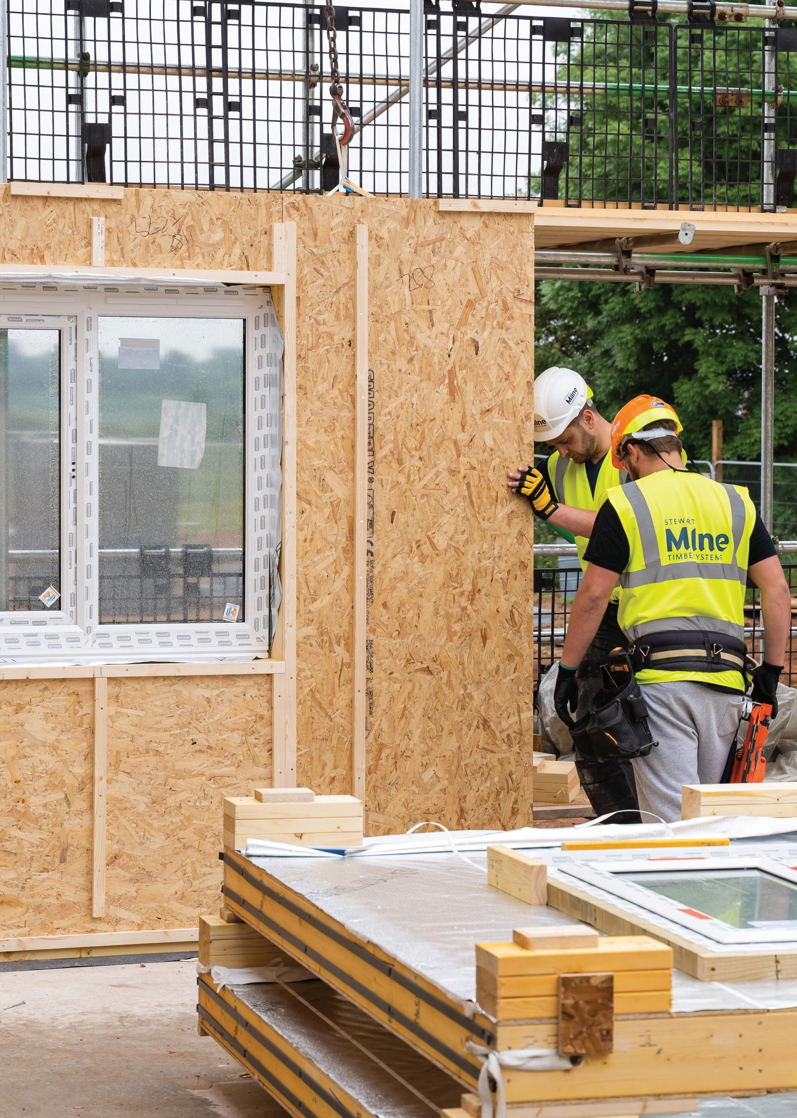
Lightweight timber frame components are manufactured from standardised structural sawn timber products together with structural wood-based sheathing panels (e.g. OSB, plywood) to form an efficient and adaptable building system.
Lightweight timber frame construction is popular due to the cost and availability of standardised structural timber products and the speed and quality of building that can be achieved.
Lightweight timber frame components can be prefabricated off-site into open or closed timber frame wall, floor and roof panels to create MMC that expedites on site construction.
What are mass timber components?
Mass timber is the name given to types of engineered timber that can be used as structural building materials. Mass timber components are made from small planks or layers of timber bonded together to increase their strength and form load-bearing components such as panels, beams and columns. Components are made in factories to precise specifications.
Mass timber components include CLT panels, LVL and glulam products suited to post and beam construction which can be combined to create a range of structural systems.
Over the last two decades, mass timber has grown in popularity globally as an alternative to carbon intensive concrete and steel. Due to its increased load-bearing capabilities, it can be used to construct larger buildings than lightweight timber frame.
22
Mass Timber Components
Lightweight Timber
Made from 3mm thick veneers bonded together under pressure using water resistant adhesive
Structural timber boards stacked in perpendicular layers and glued together under high pressure
Manufactured by bonding together layers of parallel timber lamellae, with ends finger jointed
Manufactured from structural sawn timber and structural sheathing to form prefabricated open / closed panels.
Production
Medium/high rise residential and commercial
Medium/high rise residential and commercial
Medium/high rise residential and commercial
Typical structural strength
Dimensional Tolerances Low
Low-rise residential
Typical applications
23 Timber Components
Studs and joists Glulam CLT LVL
Low
High Medium High
High
Medium
High
2.2 LIGHTWEIGHT TIMBER FRAME COMPONENTS
Lightweight timber frame construction uses timber studs and rails, together with a structural sheathing board, to form a structural frame which transmits all vertical and horizontal loads to the foundations. Floor wall and roof cassettes as well as prefabricated roof trusses are readily available within the UK market and can be manufactured from UK species.
Key information
Dimensions:
Wall studs are typically 38 x 89/140mm deep and 2.4m long (max. 5.4m) to coordinate with sheathing boards1. Solid sections between 38 x 95mm and 72 x 220mm are typically used as well as I-joists and open web joists in domestic floor construction2 Section sizes and lengths will vary depending on the span and structural requirements.
Production:
Individual structural components used in conventional timber frame construction are typically ‘dry-graded’ (moisture content <20%). Strength grading of solid sections is required to mitigate the variability of the timber before it can be used in a structural application.
Strength:
Load-bearing softwood timber members are strength graded to one of twelve strength classes, with C16 and C24 recognised as the most common.
Structural elements:
Studs I/Metal web Beams
Joists OSB / Plywood
Appearance:
Visual appearance is not a critical factor as structural elements are usually hidden between internal linings and either structural sheathing on walls or structural panels in floors.
Manufacturing standards:
BS EN14081 (BS EN338) - machine strength grading
BS EN13986 - Wood based panels, conformity and marking
BS EN15228 and BS 8417 - preservation of wood
Species:
Species include sitka spruce, larch, Douglas fir and corsican/scots pine from the UK, or spruce, pine and fir from the EU.
Carbon (A1-A3 excluding sequestration) 3 :
126 kgCO²e/m³
24 LIGHTWEIGHT TIMBER FRAME
1 Timber Frame Construction (TRADA, 5th edition); 2 www.timberbeamcalculator.co.uk (C16 floor joists); 3 see page 75
2.3 GLUED LAMINATED TIMBER
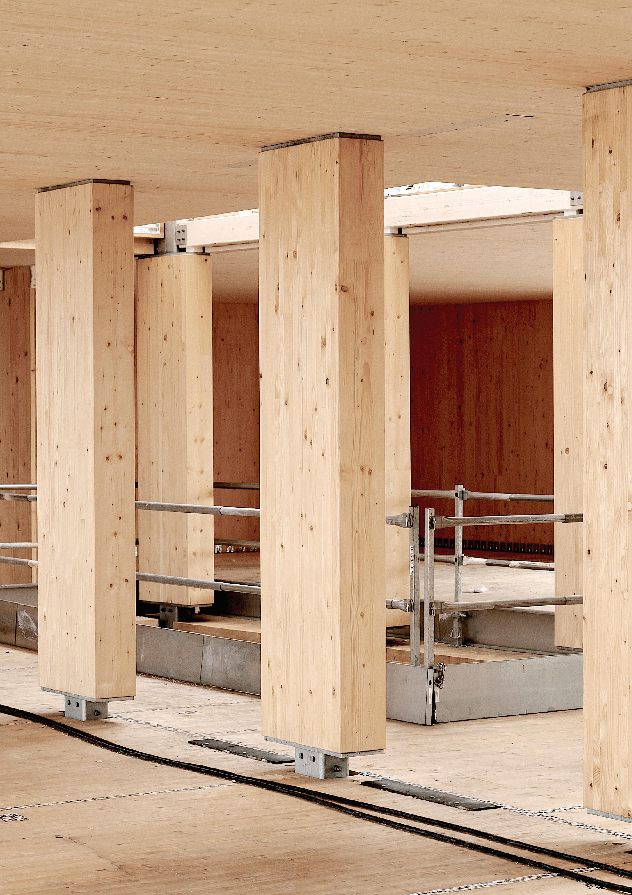
Glued laminated timber (Glulam/GLT) is made from gluing layers of timber planks to create beams and columns of various sizes. It is often used in long-span designs, where it can replace steel and concrete. It can be made in straight lengths or in curved pieces that can be used to form arched structures.
Key information
Dimensions:
Standard sizes of 80–280mm wide in 40mm increments, up to 1280mm high and maximum 18m long1. Custom sizes and shapes are available.
Production:
Produced using high strength adhesive to bond multiple finger-jointed layers of strength graded timber planks together in parallel.
Structural strength:
Glulam has a high strength to weight ratio in a uniform direction that follows the grain along the timber. Four strength classesGL24, GL28, GL32 and GL36 - are available.
Structural elements:
Beams Columns
Appearance:
Glulam is categorised into two surface qualities:
– Visual quality (VI), typically used for permanently visible surfaces in residential buildings, private homes, and public buildings.
– Industrial visual quality (IVI), typically used in buildings with lower requirements for surface quality, such as factories and warehouses.
Manufacturing standards:
BS EN 14080. All glulam components should be CE marked.
Species:
Spruce, pine, fir, larch for internal use. Pressure preservative treatment or another more durable species such as oak or sweet chestnut.
Carbon (A1-A3 excluding sequestration) 2 : 132 kgCO²e/m³
26 MASS TIMBER
1 Maximum sizes of Binderholz GLT Standard; 2 See page 75.
2.4 LAMINATED VENEER LUMBER
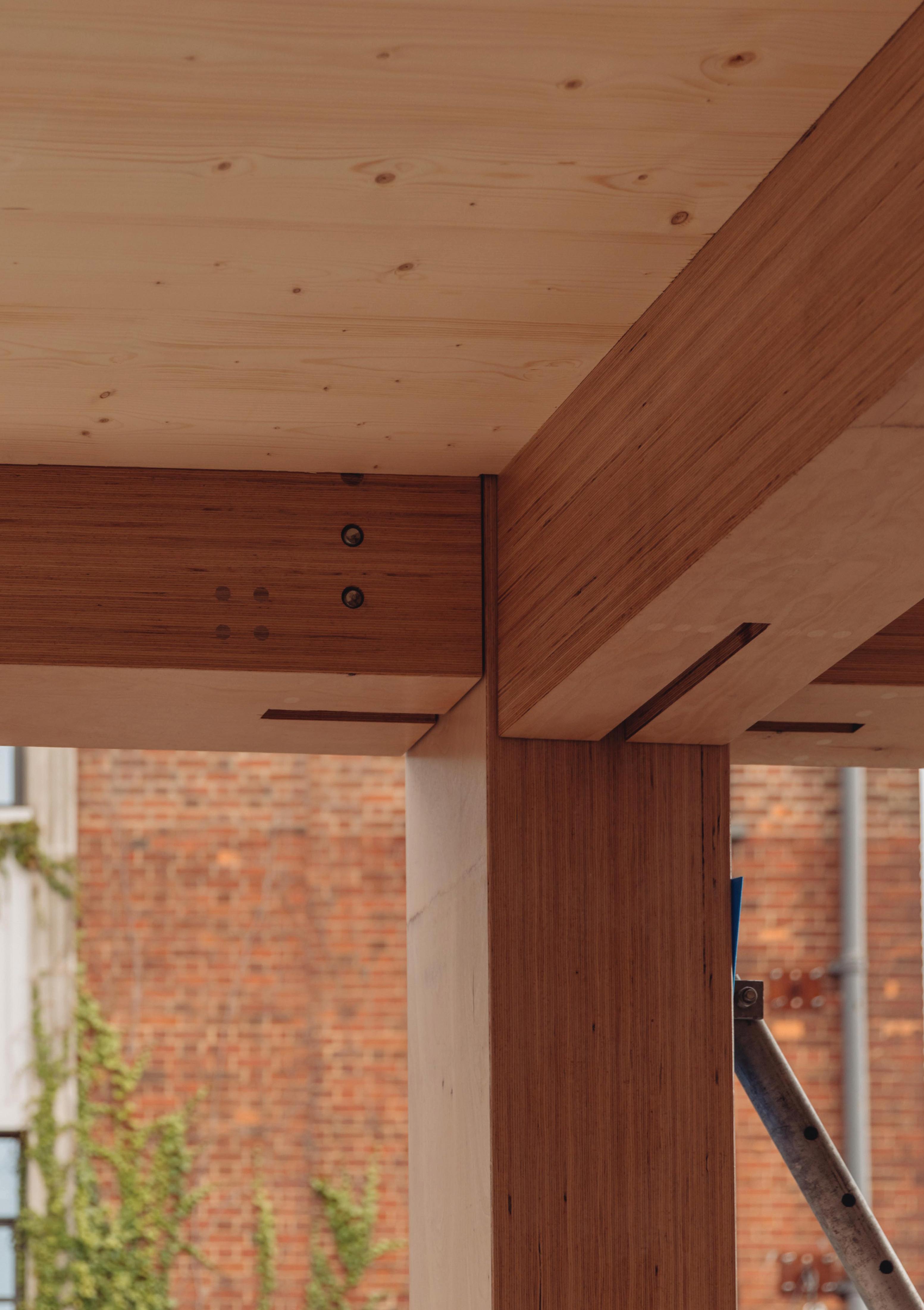
Laminated veneer lumber (LVL) is made from thin layers, or veneers, of softwood or hardwood timber bonded together. The veneers, which are created by thinly ‘peeling’ a log under heat and pressure, are mostly oriented in the same direction to create a straight and uniform material although some LVL layups incorporate a proportion of cross veneers. LVL is one of the strongest mass timber components and is twice as strong as steel in proportion to weight.
Key information
Structural strength:
Hardwood or softwood veneers can be used. They are graded during manufacture to create components with a range of strengths, with close to defect-free wood used for components with the highest performance requirements.
Structural elements: Beams
Columns
Stressed skin cassette panels
Dimensions:
Hardwood LVL can be manufactured to max. 18m long x 300mm wide x 1360mm high1. Softwood LVL can be manufactured to the same lengths; max 24.5m long x 75mm wide x 2400mm high2. Block gluing of smaller 75mm sections can enable nonstandard widths / depths to be achieved, at which point transport and machining capability becomes the limitation.
Production:
Typically made from 3mm thick veneers of strength-graded, kiln-dried timber bonded together under heat and pressure in either banded or cross banded grain direction.
Appearance:
As the sorting of veneers for LVL production is based on strength rather than visual quality, LVL is not typically categorised by visual appearance.
Manufacturing standards:
BS EN 14374 and BS EN 14279
Species:
Softwoods including spruce, pine, fir and larch. Hardwoods include beech and birch.
Carbon (A1-A3 excluding sequestration) 3: 191 kgCO²e/m³
28 MASS TIMBER
1 Pollmeier Baubuche GL75 LVL dimensions; 2 Stora Enso LVL-S and LVL-X dimensions, via James Jones & Sons Ltd; 3 See page 74.
2.5 CROSS-LAMINATED TIMBER
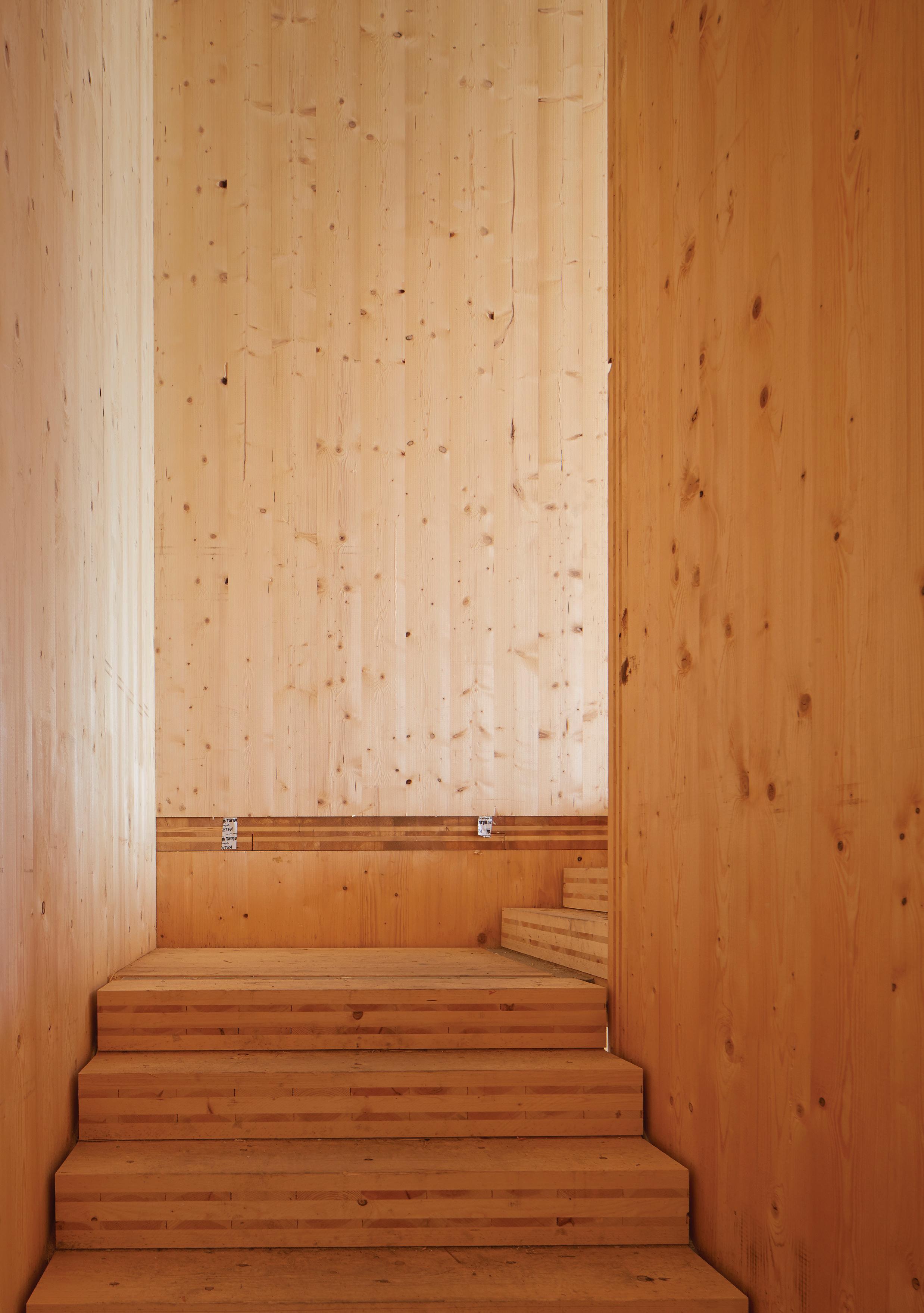
Cross-laminated timber (CLT) is a panellised product consisting of timber boards stacked in perpendicular layers and glued together under high pressure. Alternating the orientation of the layers of wood increases the stability and structural capacity of the material and provides structural rigidity in two directions. CLT panels can be used to create structural walls, floors and stairs, and can be used in composite with other materials to create prefinished facade elements.
Key information
Structural elements:
Dimensions:
Panel sizes up to 16.5m x 3.5m, with a maximum thickness of 500mm1
Production:
CLT is made from timber boards approx. 20-40mm thick finger jointed, glued and pressed to form panels of 3, 5 or 7 layers. Each layer is at 90 degrees to the one before, forming cross-lamination. Dowel and nail laminated timber are available.
Structural strength:
Similar to reinforced concrete, CLT is strong in two directions, its enhanced dimensional stability makes it suitable for wall and slab panels.
Appearance:
CLT is usually categorised into three surface qualities:
– Visual quality (VI), used for permanently visible surfaces in residential and public buildings.
– Industrial visual quality (IVI), used in buildings with lower requirements for surface quality, such as factories and warehouses.
– Non-visual quality (NVI)
Manufacturing standards:
BS EN 16351. NB this standard is recently introduced and is being adopted by manufacturers. In the meantime existing Technical Approvals facilitate CE marking.
Species:
Spruce, pine, fir, larch
Carbon A1-A3 (excluding sequestration) 3: 118 kgCO²e/m³
30 MASS TIMBER
1 Maximum sizes as quoted by KLH. Suppliers including Binderholz and Stora Enso provide panels of similar dimension, 3 See page 75.
Walls Floors
Roofs Stairs
3 TIMBER SYSTEMS
3.1 OVERVIEW
Timber components can be combined to create different structural systems. The right system for a project is determined by a number of factors including building use, height and layout alongside any construction constraints such as load bearing capacity, site conditions, time, cost, transportation and the desired level of prefabrication.
What are lightweight timber systems?
Lightweight timber systems are characterised by the use of sawn timber components regularly spaced and fastened together with nails to create floor, wall, stair and roof assemblies which form a ‘skeleton’ type structure. These systems incorporate prefabricated ‘open panel’ components that require site finishing, and ‘closed panel’ systems that are prefabricated with insulation, linings, and windows, increasing their premanufactured value. Lightweight timber systems are recognised as an efficient, safe and sustainable means of construction for low-rise buildings.
What are mass timber systems?
Mass timber systems are built using a range of mass timber components manufactured off-site to form load-bearing building structures. Mass timber can be comparable to concrete and steel in strength, however it is significantly lighter and is an environmentally friendly substitute for those traditional carbon intensive building materials. There is an evolving number of options and systems when it comes to mass timber, this study provides an overview of the three most commonly used for mid-rise buildings: panellised, volumetric modular and post and beam.
34
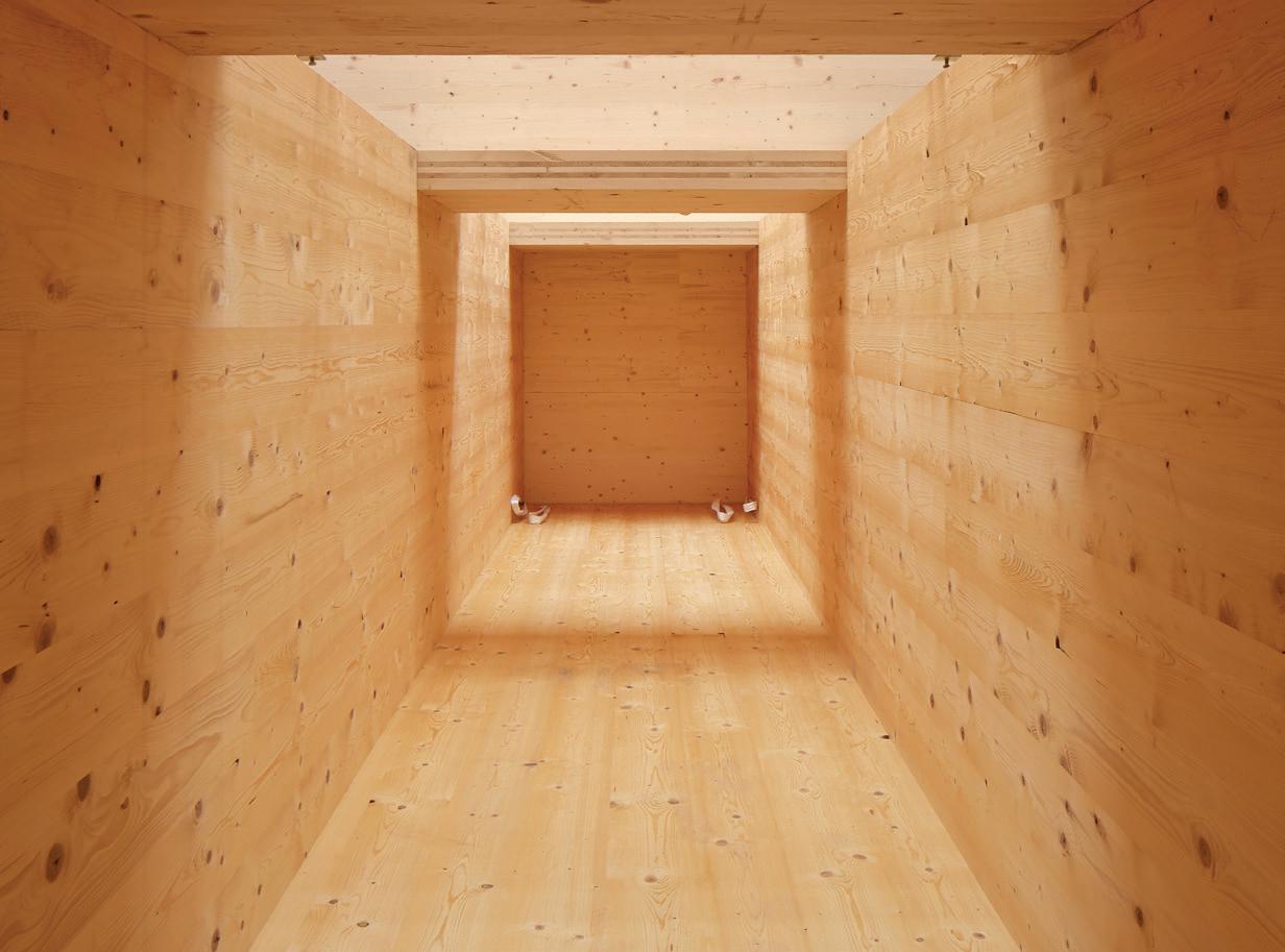
Mass timber core, Curtain Place
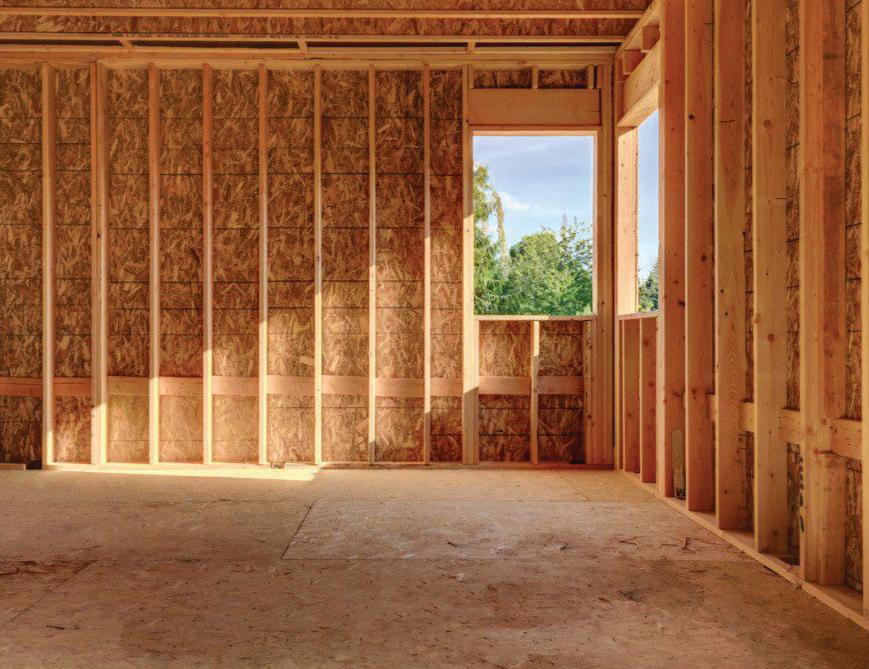
Lightweight timber frame with OSB sheathing
Most advantages
Fewest advantages
Commonly used
Less commonly used
Timber products
Low-rise residential
Mid-rise residential Commercial
Prefabrication

Construction time
Ease of transportation Layout flexibility Demountability


Timber Systems 35
Key
Lightweight timber
Mass Timber Systems
Timber frame Modular Panellised Post and beam
Typical Application
3.2 LIGHTWEIGHT TIMBER FRAME
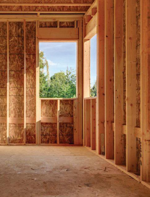
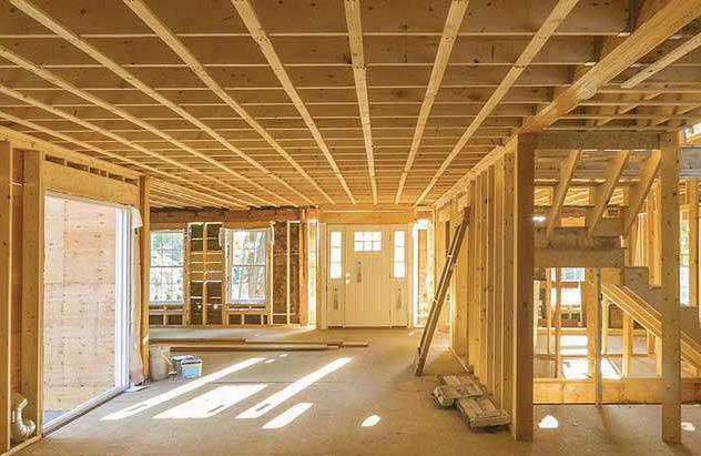
Coming to prevalence during the first half of the 19th century, lightweight timber frame construction is a particularly popular construction method for low-rise residential developments. The building methodology allows for the standardisation of components and a degree of prefabrication, without compromising flexibility of the architectural form. The components are widely available from a large number of sources including UK grown studs joists and OSB board.
Construction components
NOTE: Lightweight timber frame systems are suited to the construction of low-risebuildings
1. Floor panels
2. Internal walls
3. External walls
36 LIGHTWEIGHT TIMBER FRAME
1 3 2
Timber frame system structural components
Material Choices
Solid timber frame studs and rails can be made from several types of timber, the most common examples being spruce, pine and fir.
This is due to their low cost, availability and ease of working. Timber studs can be combined with OSB or plywood boards to form prefabricated panels.
Solid section timber can also be combined with OSB to form composite joists for floors and roofs.
Structural Systems
There are two main approaches for lightweight timber framing:
1. balloon frame
2. platform frame
LIGHTWEIGHT TIMBER FRAME 37
Timber Systems
Open panel wall components in-situ
Timber frame system: stud internal and external walls with joisted floor
Platform frame
This is the most commonly used method in the UK. Each storey is framed with floor-toceiling height stud walls and the floor deck of one floor becomes the erection platform of the next, simplifying construction.
Wall, floor and roof panels are typically prefabricated: either as open panels ( i.e. timber stud frame with sheathing typically applied to one face) or closed panels (i.e. timber stud frame pre-finished with insulation, linings, membranes and windows). Both approaches are classified as MMC Category 2 solutions, and can significantly expedite construction.
Balloon frame
In this method, similarly prefabricated panels, incorporating vertical timber studs, insulation and membranes, often span two or more floors. Intermediate floors are suspended from the face of the wall panels which become load-bearing.
Balloon frame panels require longer timber studs to construct and necessitates the installation of fire barriers at compartment lines. As a result, platform frame is the more common UK timber frame methodology.
Prefabricated lightweight panels are often combined with components like webbed joists, and mass timber beams (e.g. glulam beams, I-joists) to create hybrid solutions for open plan and nonresidential applications.
38 LIGHTWEIGHT TIMBER FRAME
Parameters of lightweight timber frame structural systems Minimum panel height 2.4m Set out to 600mm grid Joists at 400600mm grid
KEY INFORMATION: TIMBER FRAME Components
Open panels
Studs / joists, sheathing.
Closed panels
Open panels with additional linings, membranes, finishes
Engineered joists
Solid section timber or LVL, with OSB or steel webbing
Key considerations

Level of prefabrication
Applications
Timber frame system is best suited to low-rise residential applications.

Prefabricated timber frame MMC typically fall within Category 2 and are supplemented with Category 3 components like beams and trusses. Panels can be fully prefabricated to incorporate insulation, membranes, linings and cladding (closed panels).
Construction time
This method of construction can deliver significant programme savings versus traditional means, particularly where closed panels of a high premanufactured value are used. Prefabrication enables just in time delivery and minimises follow on trades.
Ease of transportation
Timber frame components are commonly 2400mm high (platform) or wide (balloon) making them easy to transport upright, ready for craning. Supplementary joists and beams are also easily transported making this an effective system for construction.
Layout flexibility
Components can be customised to address varied configurations and building types, making this a flexible method of construction, particularly for low-rise applications.
Demountability
Larger format prefabricated panels could be demounted and reused elsewhere. Individual elements including studs and joists could be removed and recycled.
LIGHTWEIGHT TIMBER FRAME 39 Timber Systems
3.3 VOLUMETRIC MODULAR
Volumetric timber construction is an effective means of construction due to the accuracy and quality that can be achieved using prefabricated timber components. Classified as a MMC Category 1 solution, timber volumetric systems use CLT or closed timber panels for walls and slabs to minimise junctions and defects, increasing quality and in-use performance. Turnkey solutions incorporating finishes and services are possible. However, the supply chain is less mature than for other systems.
NOTE: Volumetric modular systems offer the highest level of prefabrication
40 MASS TIMBER
elements Volumetric system structural components 1 2 1. Volumetric modules 2. Façade panels
Construction
Components
Volumetric modules can be made using several timber components: e.g. CLT panels, glulam beams and lightweight timber frame panels. They can also be combined with steel to create hybrid assemblies.
Modules are suited to large scale applications where repetition, structural capacity, and building performance - i.e. acoustics, airtightness and moisture control - is demanding. Care needs to be taken to design out fire spread and moisture ingress between modules.
Turnkey solutions enable client customisation of the final product and expedites construction. External elements such as membranes, cladding or windows can be installed on or off-site.
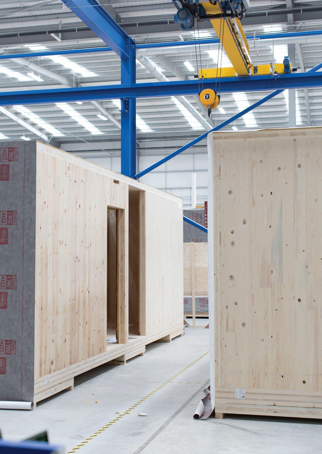
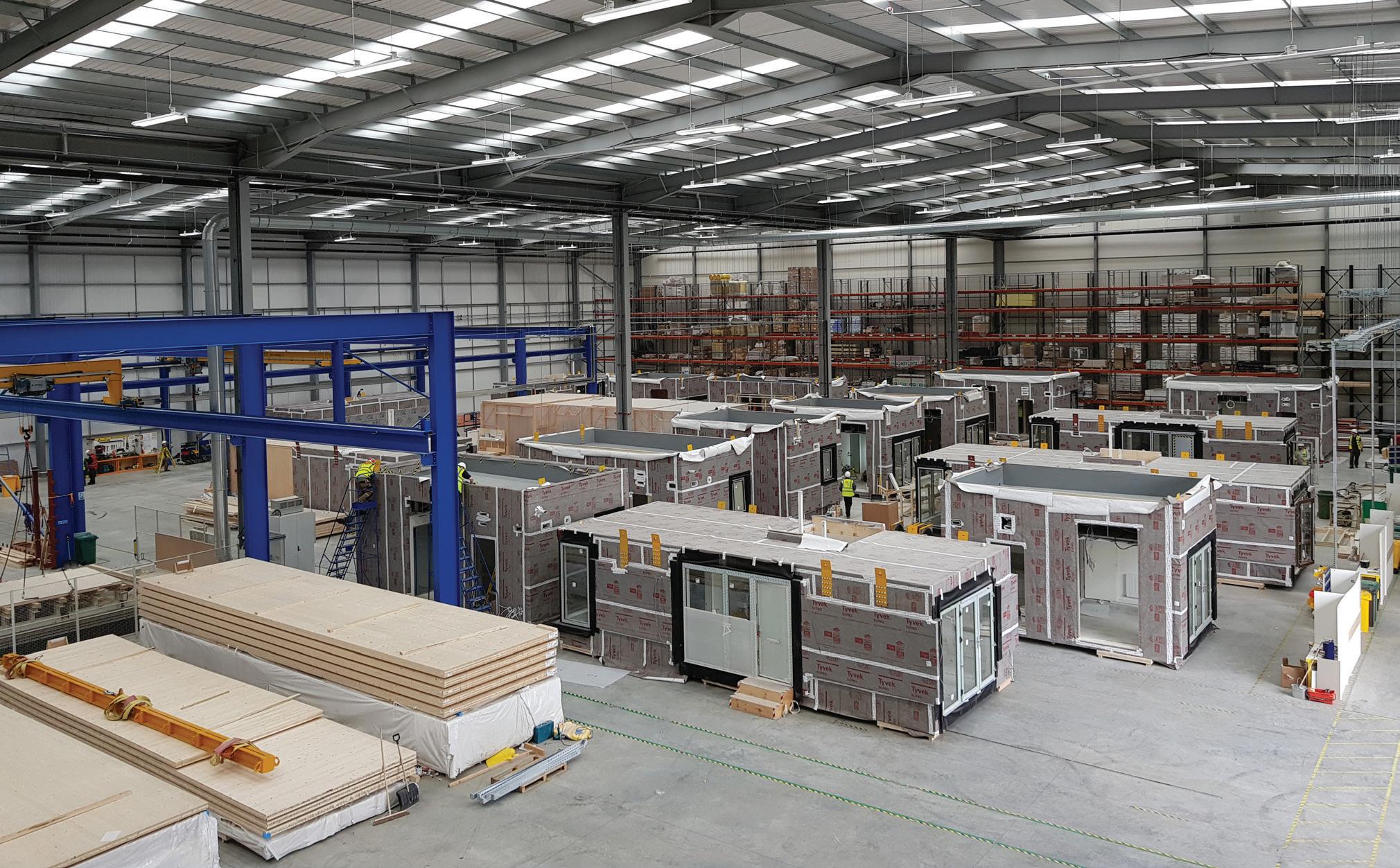
MASS TIMBER 41 Timber Systems
Volumetric modular factory showing the timber based units being finished with external membranes and windows
CLT modular units in a factory environment
Structural systems
The optimal dimensions of a volumetric module are determined by the size of the lorry and the restrictions associated with the route to the site, such as road widths and obstructions. Units larger than the optimal dimensions can result in increased transportation costs.
Although timber is a lightweight material, modules can become heavy and weigh up to 20 tonnes.
Early consideration should be given to how the modules will be stacked and lifted; as this has a bearing on the structural design of the unit and its component parts, unit connections, and the construction sequencing.
The repetitive nature of volumetric construction makes it ideal for student housing projects, hotels and residential developments that do not require large flexible layouts. If volumetric construction is used in buildings of more than five storeys, solid supporting elements must be used for stability such as supporting walls, bracing or a concrete core. This will have an impact on cost.
42 MASS TIMBER
Parameters of post and beam structural system Maximum module height 2 3.45m or 4.05m Maximum module width 1 3m (2.5m ideal) Maximum module length 2 15m or 20m 1 UK single road lanes are 3.65m, two-lane carriageways are 7.3m; 2 UK motorway bridges have a clear height of 5m.
KEY INFORMATION: VOLUMETRIC MODULAR
Components
LVL
Used for columns and beamswhere large spans are required.
Glulam
Used for columns and beamswhere height is not a constraint.
CLT
Used primarily for the floor slabs and walls in some cases.
Key considerations


Level of prefabrication
Applications
Volumetric modular is best suited to low and midrise residential applications.
Volumetric construction is considered Category 1 MMC with the three-dimensional units being manufactured in a controlled factory environment. Modules can be delivered to site fully prefabricated, with internal and external finishes applied, or provided as structural modules that require the application of on-site finishes.
Construction time
The use of volumetric modules can significantly reduce the site construction programme. Fully finished modules deliver the greatest time savings with only foundations, assembly and connections between units being required on site.
Ease of transportation
Module dimensions should be carefully planned to ensure that they take into account highway restrictions and can be delivered to site.


Layout flexibility
Various configurations are possible where CLT forms modules, as internal spaces can be liberated of load-bearing walls. Constraints apply when modules don’t align vertically.
Demountability
Independent units could be reused elsewhere if sequencing and connection design is well considered, but the modular nature of this system makes this less likely.
MASS TIMBER 43 Timber Systems
3.4 PANELLISED MASS TIMBER
Panellised construction uses off-site prefabricated mass timber panels that are assembled on site. Categorised as an MMC Category 2 solution, this system utilises the two-way spanning capability of CLT panels to form a honeycomb structure that transfers vertical and lateral loads. In this system, mass timber panels are used for both floors and walls, with the walls bearing the structural load and enhancing airtightness. In low and mid-rise buildings, panels can be used for the core of a building, replacing concrete.
Construction elements
NOTE: Typically CLT panels create floors and walls to form a structure.honeycomb
44 MASS TIMBER
1 2 3
Panellised system structural components 1. Floors 2. Internal walls 3. External walls (restrictions apply under Ap Doc Part B).
Components
Although other single span solid timber panel products are available (e.g. DLT, NLT), CLT is the typical choice for a panellised system in the UK.
Load-bearing CLT construction becomes more cost effective and structurally efficient above four storeys in height; below which lightweight timber frame systems may be appropriate.
In solid panel construction, CLT wall and floor slabs at upper levels can become thinner as structural loads reduce. This helps to minimise the volume of material required, reduce costs, and reduce loadings on the foundations.
Panels can be easily and quickly erected, reducing time on site and improving health and safety.
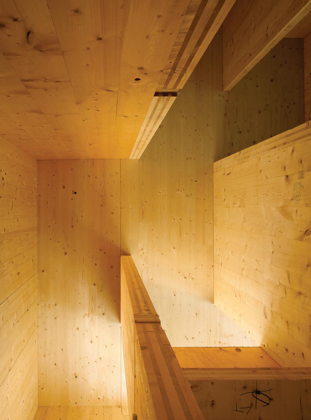
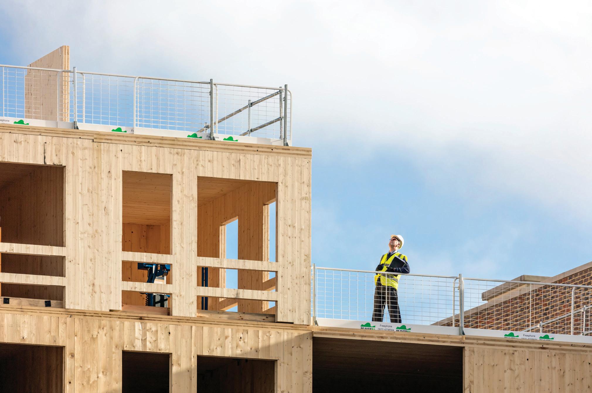
MASS TIMBER 45 Timber Systems
CLT external walls with pre-formed fall protection and window openings, Dalston Works
CLT walls and floors in Murray Grove
Structural systems
Panellised CLT construction has been widely adopted in residential buildings, where the number of internal walls and the cellular arrangement of spaces, shorter structural spans, and acoustic requirements makes it advantageous.
The connections between the panels can establish a honeycomb like structure, ensuring that walls and floors act together providing a stable, robust and structurally efficient building. CLT achieves high airtightness performance because the structure is in compression and there are few interfaces.
The structural timber can be left exposed as an aesthetic finish, resulting in cost and time savings associated with the application of secondary wall and ceiling linings. While it is possible to expose timber in residential buildings, it is more prevalent in the education and commercial sectors where fire requirements are less demanding, and well-being benefits are more keenly valued.
The lightweight properties of a panellised system makes it ideal for use on existing structures, with CLT roof extensions becoming increasingly popular. For buildings over ten storeys, the application of a hybrid approach using mass timber alongside other materials such as concrete and steel could be required in order to keep member sizes practical and to use each material to its advantage.
46 MASS TIMBER
Parameters of panellised structural system Typical height 2 3m Recommended span 6m Minimum span 1 3m Height 3 3.45 - 4.05m 1 Minimum span for material efficiency. 2 Typical floor to floor for a residential building. 3 5m in total when including the lorry bed.
Components
KEY INFORMATION: PANELLISED Applications
CLT
CLT panels can be used for all structural elements.
Panellised is best suited to mid-rise residential applications above four storeys.
Key considerations


Level of prefabrication
Panellised construction is considered Category 2 MMC with structural elements prefabricated off-site enhanced dimensional stability before services, insulation, external cladding and internal finishes are installed on-site.
Construction time
Panels are cut to size and precision manufactured. Just in time deliveries and the use of self drilling screws and proprietary brackets facilitate rapid on-site erection, while the accuracy and ease of fixing reduces follow on trades.
Ease of transportation
Panels are stacked regularly and compactly with no wasted space and no requirements for wide or long loads, offering a reduction in the number of deliveries to site compared with a traditional concrete frame.

Layout flexibility
Panellised construction is most efficient in buildings such as apartment blocks where layouts are cellular and repetitive, since internal load-bearing walls limit the flexibility of the internal layout.
Demountability
It is possible for structural panels to be dismantled and reutilised in future. Design for disassembly enables the panels to be reused as a structural product at the end of the building’s life. Mass timber can be repurposed or recycled for use in other products.
MASS TIMBER 47 Timber Systems
3.5 POST AND BEAM
Combining MMC Category 2 and 3 products, and evolving from lightweight timber frame construction, post and beam systems rely upon the load-bearing capabilities of a skeletal framework composed of slabs, beams, and posts. Utilising the enhanced strength of mass timber components means that taller, longer span structures can be built compared to a lightweight frame.
Construction elements
NOTE:
Post and beam can be divided into the primary and secondarystructure.
Primary structure
1. Beams
2. Columns
3. Suspended floors
Secondary structure
4. Façade panels
5. Internal walls.
48 MASS TIMBER
Post and beam construction components
Components
Glued laminated timber and laminated veneer lumber are the preferred materials for columns and beams due to their strength over long spans; floor slabs in this system tend to be made of solid CLT panels.
The vertical posts and horizontal beams are usually connected using hidden steel components, however visible steel bolts, large screws and even wooden fasteners can also be used.
As the building increases in height, the total load distributed down the columns is reduced and therefore column sizes can be smaller which optimises material efficiency and reduces cost.
MASS TIMBER 49 Timber Systems
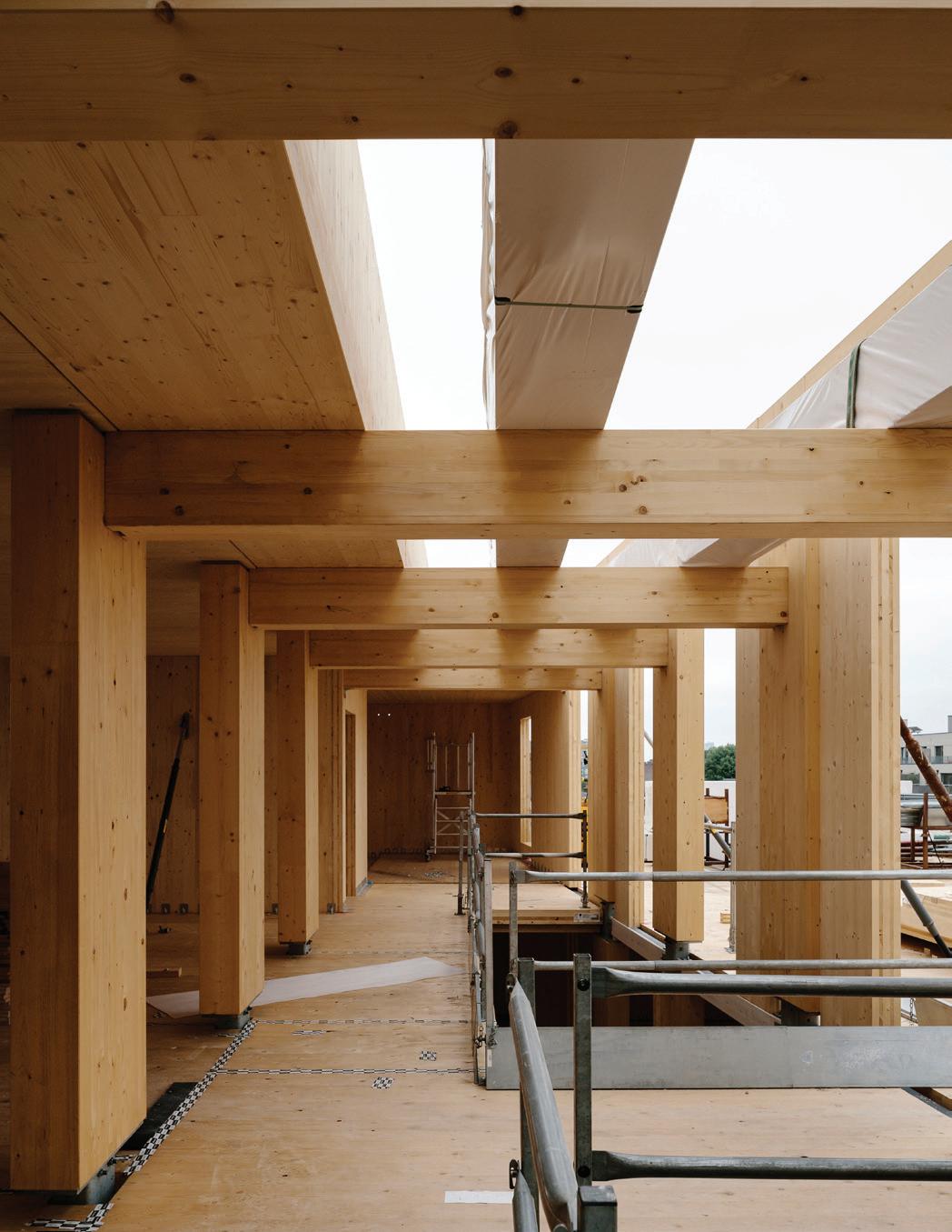
Glulam post and beam in The Greenhouse
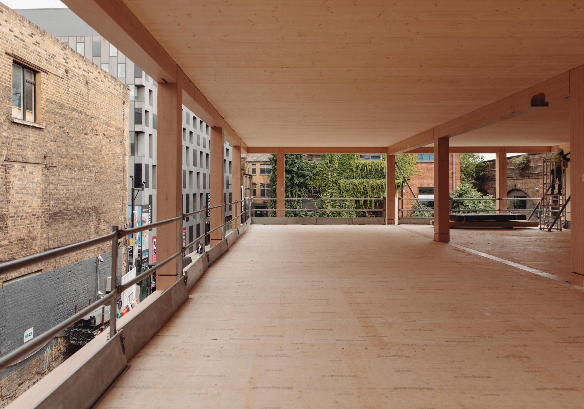
LVL post and beam frame in The Black & White building
Structural systems
The most cost-effective and materially efficient grid is approximately 6m x 6m, although larger spans are typically used in commercial applications.
Bigger spans necessitate larger components and deeper beams can have a substantial impact on floor to ceiling heights. Reductions in component sizes can be achieved using different configurations - e.g. by using two shallow beams at each column line rather than a single, deep beam or the introduction of service corridors with shorter spans.
Columns should be specified to span no more than three storeys vertically due to constraints on transportation and installation.
The post and beam system facilitates larger spans which increases the flexibility of the internal layout. As such, it is ideal for open plan applications like office buildings.
Since only the posts and beams provide the loadbearing structure, the system allows for the future adaptability of the building’s interior by facilitating reconfiguration of internal partition walls and allowing vertical connections to be made between floors through voids in the floor slabs.
50 MASS TIMBER
Typical height residential 3m Typical height commercial 4m Optimum span 1 7.5m x 6m Minimum span 2 2.25m x 4.5m 1 Ideal minimum span for material efficiency; 2 Minimum, reduced spans and beam depth used in service runs. Parameters of post and beam structural systems
NOTE: Post and beam can be used as a way of replicating steel frame construction
KEY INFORMATION: POST AND BEAM
Components
LVL
Used for columns and beamswhere large spans are required.
Glulam
Used for columns and beams
CLT
Used for the floor and roof slabs.
Key considerations


Level of prefabrication
Applications
The flexibility offered by post and beam means it can be used in buildings of all types and scales. It is most commonly used in commercial buildings.
Post and beam construction is considered Category 3 MMC with structural elements prefabricated off-site before internal partitions, services, insulation, external cladding and internal finishes are installed on-site.
Construction time
Can offer significant savings due to the prefabricated nature of the structural elements. Additional savings are achieved during construction due to the ease of erection and the accuracy of the finished structure.
Ease of transportation
Beams, columns and floors can be stacked compactly with no wasted space, offering a reduction in the number of deliveries to site compared with concrete frame.


Layout flexibility
Post and beam systems are ideal for applications where flexible layouts are a priority as internal walls aren’t load-bearing, allowing the creation of large open spaces.
Demountability
The detailing of post and beam structures can enable structural elements to be disassembled and then reutilised or reused in alternative applications.
MASS TIMBER 51 Timber Systems
TIMBER
3.6 HYBRID SYSTEMS
Hybrid mass timber systems use mass timber components in conjunction with other materials including steel and concrete. Hybrid systems capitalise on the performance and structural properties of each building material to maximise structural efficiency, minimise the amount of material used and drive cost down.
Components
A hybrid system can range from a full timber solution combining lightweight timber frame with mass timber components to a timber-steel or timber-concrete approach. A hybrid construction can also exist when a mass timber building requires concrete to be used in the core for lateral stability.
Hybrid systems can be more challenging to procure and construct, as prefabricated steel and concrete components will need to be sourced from different suppliers to the mass timber.
However, the overall benefits are similar in terms of precision, quality and construction expediency.
Floor slabs account for the majority of structural material used in a building. To reduce the carbon impact, hybrid systems should therefore prioritise the use of timber in horizontal elements.
Steel and concrete components have a higher embodied carbon profile compared with timber.
Structural systems
Due to their structural performance characteristics, steel and concrete are most commonly used as beams and columns in hybrid systems.
Castellated steel beams can be used to facilitate highlevel services distribution, providing flexibility for the installation and future adaptation of MEP services. Steel beams are typically used where larger spans or height constraints become an influencing factor on design decisions.
Precast concrete elements offer the possibility of wider spans, while concrete columns can be installed at ground level where flood risk is a consideration.
Although not as lightweight as timber-based solutions, the use of hybrid systems reduces loads on foundations. This makes hybrid systems advantageous in situations where ground conditions, easements, or adjacencies with other properties and infrastructure may be challenging to overcome traditionally, while still being materially efficient and reducing carbon emissions...
52 MASS TIMBER
Timber-steel hybrids
These are often used in commercial buildings where large spans are required to achieve open plan spaces and maintain a high floor to floor height.
Steel castellated beams allow services to run within the beams’ depth, reducing the overall floor buildup and corresponding building height, facilitating future adaptation of services and enabling timber soffits to remain exposed as an internal finish.
Timber-concrete hybrids
Combining CLT slabs with precast concrete columns and beams, smaller-section concrete columns and larger spans helps to maximise net internal floor area in, typically, commercial developments.
The transport and installation requirements are similar to those of a full timber structure, as components are prefabricated. Additional consideration must be given to the weight of concrete components and the interface between materials.
Concrete-timber hybrid
Generally used in commercial buildings, this system combines mass timber columns with prefabricated composite timber slabs - e.g. CLT with a concrete topping.
The use of composite slabs helps to mitigate vibration, minimise floor thickness and increases building mass, making it an effective solution in taller buildings.
However, it has more onerous lifting and transport requirements, and can be more difficult to procure than a 100% timber structure.
MASS TIMBER 53 Timber Systems
4
APPLICATIONS
4.1 OVERVIEW
The structural performance of mass timber means that wood construction is no longer limited to small scale projects constructed from lightweight timber components. While lightweight timber remains preferable for the construction of low-rise developments, mass timber is now a viable structural option for taller buildings in both the commercial and residential sectors.
Lightweight timber frame applications
Material availability, universally understood construction methodologies and proven rate of success has resulted in lightweight timber being widely used in the UK for constructing low-rise residential buildings. Advances in off-site manufacturing have increased the efficiency of lightweight timber construction by reducing onsite fabrication times and increasing construction accuracy. Structurally, lightweight timber systems are best suited to buildings up to four storeys in height with relatively small structural spans.
In Scotland, lightweight timber frame homes already account for around 80% of all new housing, compared to 23% in England: the market is expected to grow 1. FTSE 100 developers such as Barratt Developments are prioritising the use of timber frame over traditional building methods and are investing in lightweight timber frame prefabrication facilities.
Mass timber frame applications
The UK has one of the most diverse ranges of mass timber buildings in the world, with examples across most sectors including residential, commercial and education. Mass timber systems are most suited to taller buildings where the structural requirements become more onerous, and therefore more difficult to achieve using lightweight timber frame. Above four storeys, mass timber components can be optimised for material efficiency, making it a cost-effective solution.
Mass timber is prevalent in low-rise schools and warehouses where large spans, speed of construction and exposed finishes are desirable, delivering a low-carbon alternative to concrete and steel construction. Benefits such as the improvements to health and well-being associated with inhabiting timber buildings give further incentive for developers to prioritise mass timber over traditional construction methods.
56
¹ MTW research report, ’Timber Frame Construction Market 2022’
Commercial
5+ storey commercial developments
Mid-rise residential
5-10 storey residential developments
Low-rise residential
Lightweight Timber Applications Mass Timber Applications
1-4 storey residential developments, including terraces and low-rise apartment buildings
Timber frame Volumetric Panellised Post and beam
Timber typologies
57 Applications
4.2 LOW-RISE RESIDENTIAL
Low-rise residential housing accounts for 94% 1 of all residential buildings within the UK. This highlights the expansive market for typologies that lend themselves to construction within this category. Lightweight timber frame is the most common typology found in this application, as it is familiar to contractors and easy to procure making it a cost effective solution.
Suitable typologies
Timber Frame
The most common form of low-rise residential housing.
Volumetric
The fastest installation times for residential housing.
Layout considerations
The regular spacing of studs, joists and roof members in lightweight timber frame systems are coordinated to the corresponding dimensions of board materials (2400mm x 1200mm), dictating a typical structural grid of 400mm or 600mm.
Wall thickness varies in response to applicable structural, thermal and fire resistance performance requirements, influencing setting out. Volumetric modular solutions can be an effective solution for developments where there a lots of homes of the same layout and scale.
To ensure the efficient application of this system, layouts should be coordinated for efficient services layouts, designed to reflect site access and transport restrictions, and the manufacturing constraints of the modular components.
Building height considerations
Low-rise buildings are considered to be buildings below four storeys high. In lightweight timber frame systems, prefabricated panels will typically be manufactured to heights of 2400mm, reflecting dimensional constraints of proprietary products. Volumetric modular components will be taller, to incorporate ceilings and services and must be coordinated with site access and transport limits.
Fire safety considerations
There are fewer regulatory restrictions on the use of timber in low-rise buildings, making it easier to use. Lightweight timber frame components are typically lined with non-combustible boards to provide the required fire resistance, as dictated by the location and function of the relevant component.
Lightweight timber frame systems are more vulnerable to fire than mass timber volumetric systems during construction, so care should be taken to ensure that robust fire prevention strategies are implemented to mitigate risk2
58 LIGHTWEIGHT TIMBER FRAME
1 English Housing Survey 2017-2018; 2 The Structural Timber Association ‘16 Steps to Fire Safety’ provides guidance.
CASE STUDY PROJECTS: LOW-RISE RESIDENTIAL
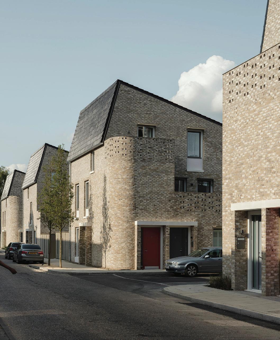
Goldsmith Street
Typology:
Lightweight timber frame
Height: 2 to 3 storeys
Size:
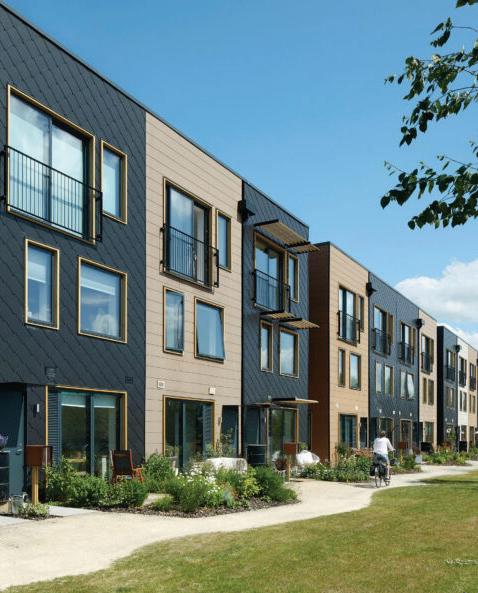
45 houses, 60 flats
Completed in 2018, this awardwinning development utilises prefabricated closed panel timber frame components, and floor and roof cassettes incorporating engineered timber joists, to deliver 105 affordable PassivHaus certified homes.
Citu homes, Leeds
Typology:
Lightweight timber frame
Height: 3-storey
Size:
516 homes (houses and apartments)
This regeneration project in Leeds uses prefabricated closed panels manufactured on site by clientdeveloper Citu to deliver carbon negative homes that sequester 23 tonnes of CO 2 e within their timber structure.
LIGHTWEIGHT TIMBER FRAME 59 Applications
Climate Innovation District Leeds, Citu
Goldsmith Street Mikhail Riches
4.3 MID-RISE RESIDENTIAL
Due to the demand for housing in urban areas, mid-rise residential buildings account for a large proportion of development in the UK. The structural properties of mass timber systems mean they are particularly suitable for buildings of 5-10 storeys, and the prefabrication of mass timber components enables buildings on constrained sites to be more easily constructed, more quickly.
Suitable systems
Volumetric
Utilises the highest level of prefabrication.
Panellised
Fewer follow on trades as more walls are prefabricated.
Post and Beam
Improved level of internal layout flexibility.
Building height considerations
Mass timber systems have been used to construct residential buildings of up to ten storeys in the UK, and taller buildings internationally, demonstrating their viability and capability.
In England, building regulations prejudice against using timber in the external walls of residential buildings above 18m.
A solution for developments above this threshold can be hybrid systems where an internal mass timber structure is combined with a non-combustible façade (e.g. light steel frame) and structural core of mass timber or, more commonly, in-situ concrete.
Structural grid considerations
The repetitive and cellular layout of residential buildings lends itself to the use of panellised and volumetric systems; as vertical load paths are consistent. It is important to work to system parameters to maximise efficiency and minimise costs.
For panellised, a 6m grid is recommended and works well with most apartment typologies. The grid for volumetric modular will be influenced by transport restrictions on delivery to site.
Post and beam, and hybrid systems, are typically the most flexible as spans can be larger, although a 6m span in one direction is desirable to enable the efficient use of CLT slabs.
Fire safety considerations
Timber buildings are subject to the same statutory regulations as traditionally constructed buildings, with the requirements for external walls in tall residential buildings being a key consideration.
The risk of fire in a timber building is highest during construction, so it is important that a fire risk assessment and robust site management plan is in place to protect the timber system at all times.
60 MASS TIMBER
EXAMPLE PROJECTS: MID-RISE RESIDENTIAL
Dalston works
System:
Panellised CLT
Height:
5-10 storeys
Size:
121 apartments, 3,500 m2 commercial
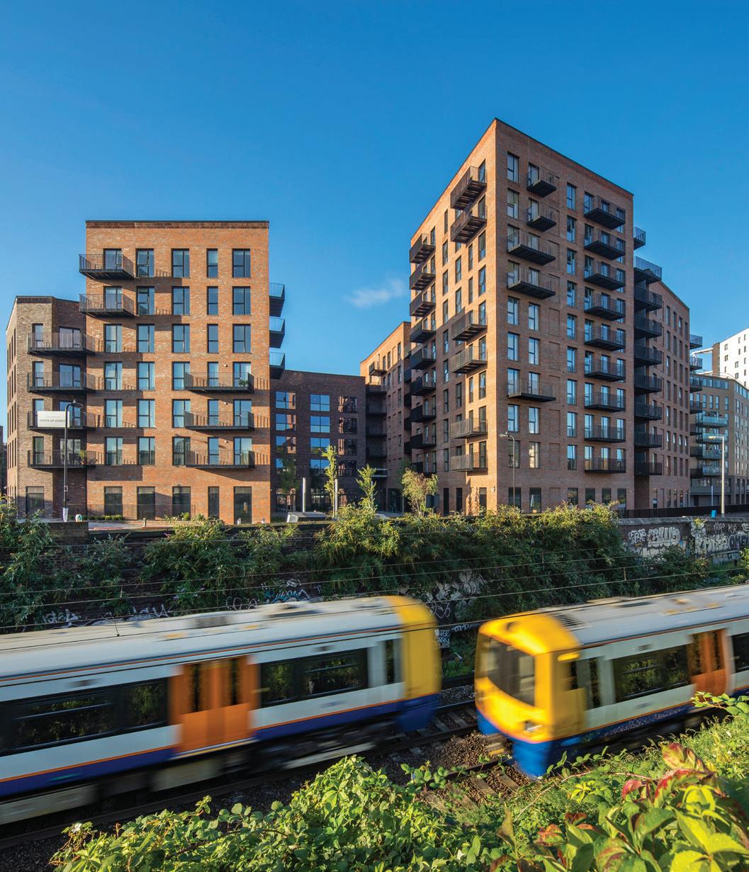
Built using 4649m 3 of CLT, the timber structure sequesters 3,576 TCO 2e to become a long-term carbon sink. The use of lightweight CLT mitigated piling and helped maximise density. Delivered in 111 lorry loads, CLT expedited construction.
Lewes Road
System:
Panellised timber hybrid
Height:
5 storeys
Size:
48 student studios and communal space
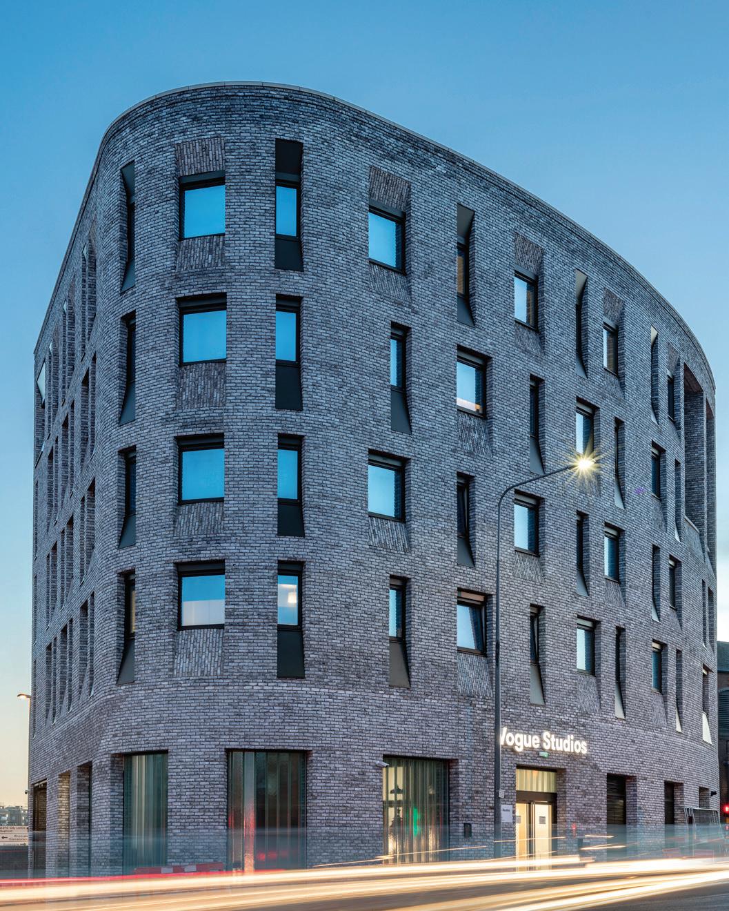
Offsite technologies are often adopted for large-scale projects. Lewes Road demonstrates how modern methods of construction can be successfully and efficiently utilised for small, inaccessible and complex sites.
MASS TIMBER 61 Applications
Dalston Works
Lewes Road
4.4 COMMERCIAL
Mass timber is an increasingly popular choice for commercial applications due to its low embodied carbon, material efficiency and demonstrable sustainability. The demands associated with commercial buildings can be cost effectively achieved using post and beam systems, and employers are investing in timber buildings to create well-being focussed workspaces for new and existing staff.
Suitable systems
Post and beam
Large flexible office spaces are easily achieved. Hybrid
Where flexibility is essential.
Building height considerations
While there is no limit on building height for post and beam systems in commercial applications, considerations when building over 18m include:
– Non-combustible material for stair/lift cores and/or external wall
– Provision of sprinklers
– Providing an additional escape staircase
If a building is over 30m, specialist thermo-setting glues should be used in the manufacture of timber products.
Structural grid considerations
An optimal structural grid of around 6-9m x 6m provides an efficient and flexible layout
for most commercial applications. The lack of loadbearing internal walls means internal partitions can be rearranged depending on tenant needs.
A structural core is needed to increase the stability of the building, this can be constructed from panellised mass timber or another material depending on project requirements.
Fire safety considerations
Compartmentation is required in mass timber commercial buildings in order to retain the fire and associated damage within the floor of origin. Firefighters will encounter a one-floor fire, as in any conventional commercial building.
Nevertheless, given the potential longer duration of fires in commercial spaces, firefighters may encounter a burning structure. Firefighters will not be required to intervene until the structure self-extinguishes.
In a mass timber building firefighters will be required to suppress smouldering fires and to identify the occurrence of self-extinction. The former is not an unusual practice, nevertheless specific training associated to timber structures should be provided. The risk of fire in a timber building is highest during construction, so it is key that a fire risk assessment and robust site management plan is put in place.
62 MASS TIMBER
EXAMPLE PROJECTS: COMMERCIAL
6 Orsman Road
System:
Hybrid
Height:
6 storeys
Size:
4,680 m²
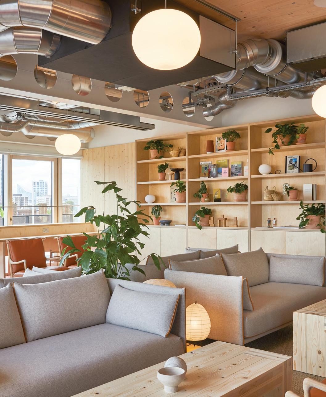
This office building uses a hybrid CLT and steel structure to reduce its whole life carbon impact. The services are exposed, running through the castellated beams, maximising the floor to ceiling heights.
Black & White Building
System:
Post and beam
Height:
6 storeys
Size:
4,480 m²
This flexible office building uses LVL posts and beams with CLT slabs to create open floor plates devoid of load-bearing internal partition walls. MEP is carefully coordinated to minimise visual intrusion, and the layout can be easily adapted as future demands change.
MASS TIMBER 63 Applications
6 Orsman Road
Black & White Building
5 OTHER CONSIDERATIONS
5.1 FIRE
As wood is combustible it leads to an inevitable concern about the fire performance of timber buildings. However, it is important to understand that all materials have their limitations when exposed to a fire. No construction method or material is immune to fire so this should not be a constraint particular to building in timber, but an important design parameter for all construction.
Performance requirements
During a fire, there are three performance requirements of a building’s structure:
– Compartmentation
– Structural stability
– Serviceability
These have to be maintained until the complete consumption (burn-out) of the fuel available - typically combustible furnishings.
In timber buildings, failure to meet any of the three functional requirements has the potential for much more severe consequences than for non-combustible materials as it could result in the total loss of the structure. Therefore design quality control, detailing and maintenance must be to a high standard.
Fire resistance of timber
Buildings constructed from noncombustible structural materials, such as concrete, are designed to retain their structural functionality in a fire until the complete consumption (burn-out) of the
fuel available - typically combustible furnishings, as previously mentioned.
When calculating the structural performance of a concrete building, engineers include a thermal load on the structure to ensure the building will retain its structural functionality during a fire. This is known as fire resistance.
Wood is a combustible material, and will eventually ignite as a fire grows. Once it ignites, timber will only retain its structural functionality until the complete consumption of the available fuel if the timber stops burning unassisted (i.e. self-extinction).
Fire resistance itself is therefore not a methodology that can be directly used for the purpose of establishing that a timber structure fulfils its functionality in the event of a fire. Alternative approaches, such as protection of the timber structure, can be used to ensure fire performance requirements are met.
Protecting the timber structure
To ensure compartmentation and structural stability different approaches can be used to protect the timber structure, depending on the structural typology and timber products used. Two approaches are detailed in the table opposite.
66
Mass timber systems
Demonstrate the following to ensure the performance of the mass timber elements:
1. Encapsulation must show adequate thermal and mechanical performance to guarantee the timber structure will not reach a conservatively low pyrolysis temperature (ex. 250 o C) until burn-out of the combustible furnishings.
2. As the structural timber will not participate in the fire, the principle of fire resistance can be used. However, the failure criterion must include the prevention of pyrolysis of the structural timber.
3. Adequate performance in all three functionality requirements: compartmentation, structural stability and serviceability.
Demonstrate the following to ensure the performance of the mass timber elements:
1. The presence of exposed timber in walls and other structural elements will not alter the early progression of the fire disabling the separation of risks strategy.
2. All structural timber will self-extinguish upon the consumption of a worst-case combustible furnishings load plus the feedback loop of the pyrolysing timber itself.
3. Delamination will not occur. The structure will retain the three functionality requirements: compartmentation, structural stability and serviceability
Lightweight timber systems
Demonstrate the following to ensure the performance of the lightweight timber elements:
Encapsulation must show adequate thermal and mechanical performance to guarantee the timber structure will not reach a conservatively low pyrolysis temperature (ex. 250 o C) until burn-out of the combustible furnishings. As the structural timber will not participate in the fire, the principle of fire resistance can be used. However, the failure criterion must include the prevention of pyrolysis of the structural timber.
Adequate performance in all three functionality requirements: compartmentation, structural stability and serviceability.
Full Encapsulation Timber is prevented from igniting or pyrolysing by being covered in protective material, e.g. plasterboard certified to perform until the fire self extinguishes.
Lightweight timber studs and joists are typically too small to allow for charring to enable self-extinction. Therefore, exposed timber is not generally a suitable protection strategy.
Exposure Timber is oversized so that a char layer is created, acting as a thermal barrier that prevents the timber from degrading until the fire self extinguishes
Protection strategy
67 Other considerations
5.2 MOISTURE
It is essential that moisture management is considered in all construction types, however it is particularly important in timber buildings since the hygroscopic properties of wood allow it to absorb and retain water. These same properties allow timber to dry, however if moisture becomes trapped, fungal decay can develop compromising the timber’s structural performance.
General approach
There are many moisture ingress sources from plumbing leaks to membrane failures. Reducing the risk of damage from moisture should be considered at all project stages to ensure the building is designed effectively for moisture durability. This can be split into stages:
1. Moisture management through design
2. Moisture management during construction
3. Moisture management post completion
Moisture management plan
A project-specific moisture management plan should be established at the start of a project. There are a number of resources available to refer to in writing a moisture management plan:
– STA Advice Note 14 - Robustness of CLT Structures - Part 1
Key principles for moisture durability, providing good practice guidance for the design, concept detailing and installation of CLT. Applicable from design stages through to construction.
– STA Technical Note 24
Moisture protection during construction provides a checklist of best practice water management/ moisture control measures for construction, however it is not a substitute for project specific moisture management controls.
– The National Structural Timber Specification for Building Construction
Provides guidance for compiling bespoke project specifications using the TRADA NSTS template, including a detailed moisture management plan (chapter 4.7). This document is applicable from design stages through to construction.
– TRADA Timber 2021 Industry Yearbook ‘Moisture Management’ chapter’
Provides general tips and considerations for best practice moisture management strategies from design stages through to construction.
– TRADA Cross-laminated Timber Design and Performance
Provides an in-depth guide to the design and performance of CLT at all stages of design and construction.
68
Mass timber systems
Demonstrate robust detailing of areas at highest risk of leaks/moisture damage, such as:
–roofs –‘wet’ areas with active plumbing fixtures
–areas in contact with the ground floor slab
–connections and fixings
–openings and (service) penetrations
Protection from moisture can be provided through careful detailing, ventilation zones, applying layers of protection and leak detection such as automatic cut-off valves see STA Guidance.
Provide moisture management control plan (MMCP) that demonstrates protection from sources such as:
Lightweight timber systems
Demonstrate robust detailing of areas at highest risk of leaks/moisture damage listed under mass timber systems and also considering
Moisture management through design
–utilising damp proof membranes where appropriate –ensuring cavities are drained and ventilated.
–where vapour check plasterboard linings are used joints must be appropriately filled, taped and finished.

Same as mass timber, plus:
–precipitation,
–humidity –ambient sources,
–MEP and fire protection trades. MMCPs should be specific to the project, and form part of the construction management plan submitted as part of any tender return.
Regular inspections should be carried out. If timber has been exposed to moisture, it should be assessed to determine the best method to remediate, considering factors such as:
–cavities should be kept clean and free of obstructions
Moisture management during construction

Protection strategy
Same as mass timber, plus:
–Total area of timber exposed to moisture
–Duration of the exposure to moisture.
–Depth of moisture exposure
–Presence of mould or decay
–gather moisture data measured from areas most at risk of wetting e.g. sole plates and flat or pitched roof edges
Moisture management post- completion
If found early, remediation might be as simple as allowing the timber to dry.
–If high moisture content is identified, use in-situ drying before closing panels with insulation/membranes which restrict drying pathways. If factory-insulated closed panels become wet, remove internal VCL and wet insulation to aid the drying process.

69 Other considerations
5.3 ACOUSTICS
Using performance data
As with any material, delivering high acoustic performance in timber buildings requires careful considerations to reduce vibrations and sound transmission. However, with considered design, occupants can enjoy the same privacy and acoustic performance in timber structures as they have come to expect from steel and concrete buildings. Primary methods of improving this are to add additional layers of mass, insulation and separation (voids) ref The CLT Handbook 1 for more detail on mitigating measures.
Most acoustic design relies on data from similar historical installations. This allows acoustic engineers to design efficiently and be certain their designs will perform at the level required.
There is a wealth of knowledge of the performance of lightweight timber construction details, including accredited robust details. While there is less test data currently available for mass timber, studies have found the acoustic performance of completed schemes often exceeds expected design levels.
Airborne sound
Due to its increased density; mass timber, particularly CLT, offers noticeable improvements over its lightframed counterpart for airborne sound transmission.
Impact sound
The density of mass timber is an acoustic asset, however the connection between walls and floors provides acoustic pathways, known as flanking transmission, that can transmit impact sound over large distances if the building is not properly insulated and isolated. 1
Vibration
While timber offers benefits in terms of strength to weight ratio, the relatively lightweight nature and stiffness of the material can make it more susceptible to vibration particularly with long spans.
The principal source of vibration is footfall, with acceptable levels depending on the use of the space. Permitting lower vibration performance for material efficiency should be discussed in the context of user’s ability to ‘feel’ vibrations caused by other occupants, which are typically less problematic in offices as opposed to residential.
Installation
As with any acoustic design, performance relies on correct installation. The solidity and accuracy of mass timber construction and the workability of the material helps to limit the scope for failure of acoustic measures.
70
Sylvian Gagnon and Ciprian Pirvu (ed.), CLT handbook: cross-laminated timber, FP
Mass timber systems
To reduce the transmission of impact sound separation is required between the interior spaces and the mass timber structure. This can be provided using layers of compressible insulation or additional mass or voids. Alternatively, acoustic breaks between the joints of walls and floors can be used. There is an increasing pool of suppliers of supplementary materials that have tested accredited details for mass timber.
To help prevent transmission of airborne sound, it is possible to create high levels of insulation by using one or two layers of plasterboard on either side of the mass timber panel.
Mounting plasterboard on acoustically insulating brackets and adding acoustic insulation will further increase performance. Alternatively, use two mass timber panels separated by an air gap.
Lightweight timber systems
A wealth of information on acoustic performance in lightweight timber buildings is available, including:
E Robust Details 2022
–Part
NHBC Standards 2022
–
Impact sound mitigation
Additionally, many suppliers of products and systems used to manage acoustic performance e.g. insulation and plasterboard, have accredited details for lightweight timber frame construction.
Airborne sound mitigation
Protection strategy
Response factor analysis should be carried out early in the design to identify areas that may be susceptible. Reduction of large spans is generally a key first principle. Adding mass such as screeds and/or soffit boards can be included but the carbon and end of life impact must also be considered.
Design solutions for light-frame wood construction focus on ways to minimize sound from airborne sources and movement by people within the building. For walls in light-frame wood structures, sound isolation can be accomplished by using partitions with a high mass or using low mass systems separated by air spaces. For floors and ceilings, noise control can be improved by increasing its mass.
Soft floor finishes or floating engineered hardwood can further mitigate sound transmission..
Structural Vibration
71 Other considerations
6 FURTHER READING
While there is already a considerable amount of literature on timber structures, the range of references is growing constantly. The list below is a selection of the principal reference documents on building in lightweight and mass timber.
Alsmarker T, Moisture-proof CLT construction without a full temporary shelter, Swedish Wood, 2022
Andrew Bernheimer (ed.), Timber in the City: Design and Construction in Mass Timber, Oro Editions, 2015
CAST, Modern Methods of Construction , 2019
Hermann Kaufmann, Stefan Krötsch, Stefan Winter, Manual of Multi-storey Timber Construction, Detail, 2022
James Norman, Structural timber elements, a pre-scheme guide , Exova BM TRADA, 2016
Josef Kolb, Systems in Timber Engineering , Birkhäuser, 2018
Joseph Mayo, Solid Wood: Case Studies in Mass Timber Architecture, Technology and Design, Routledge, 2015
London Energy Transformation Initiative, LETI Climate Emergency Design Guide. How new buildings can meet UK climate change targets. LETI, 2020
Milner, M. PRPA 4 Design guide to separating distances during construction for timber frame buildings. STA 2019
Michael Dickson, Sustainable Timber Design , Routledge ,2015
Mike Berners-Lee, How Bad Are Bananas? The carbon footprint of everything , Profile Books Ltd, 2010
Pablo Van Der Lugt, Tomorrow’s timber. Towards the next building revolution , Material District, 2020
Petter Bergerud, Experimental Wooden Structures , Bergen Academy of Art and Design, 2015
Robin Lancashire and Lewis Taylor, Timber Frame Construction 5th edition , TRADA 2011
Robert Hairstans, Mass Timber - an Introduction to Solid Laminate Timber Systems , Arcamedia, 2018
Simone Jeska, Emergent Timber Technologies - Materials, Structures, Engineering Project s, Birkhauser, 2015
Susan Jones, Mass Timber: Design and Research , Oro Editions, 2018
Sylvian Gagnon and Ciprian Pirvu (ed.), CLT handbook: cross-laminated timber , FP Innovations and Binational Softwood Lumber Council,2011
Ulrich Daniel, Turning Point in Timber Construction - A New Economy , Birkhäuser, 2016
Various, Cross-laminated timber, Design and Performance , Exova BM TRADA, 2017
Virginia McLeod, Detail in Contemporary Timber Architecture , Laurence King Publishing, 2010
Further Reading 74
Photographs
p11 Waldverband Österreich © Confederation of European Forest Owners (CEPF)
p13 The Black & White Building © The Office Group (TOG) Daniel Tucker
p15 Logs © Waugh Thistleton Architects 100 Projects UK CLT
p17 Multiply-clt © American Hardwood Export Council Petr Krejci
p19 The Black & White Building © The Office Group (TOG) Jake Curtis
p25 Timber Frame and Offsite Construction © Donaldson Timber Systems
p26 Cambridge Heath Site © Waugh Thistleton Architects Tim Crocker
p29 The Black & White Building © The Office Group (TOG)
p31 Curtain Place © Waugh Thistleton Architects Will Pryce
p34 House Under Construction Image 1 © David Papazian Photography
p34 Curtain Place © Waugh Thistleton Architects Will Pryce
p37 House under construction Image 2 © David Papazian Photography
p37 Timber Frame System © Ducere Construction Services
p41 NU Build Factory Image 1 © Swan Housing Agnese Sanvito
p41 NU Build Factory Image 2 © Swan Housing Agnese Sanvito
p45 Muray Grove © Waugh Thistleton Architects Will Pryce
p45 Dalston Works © Waugh Thistleton Architects Daniel Shearing
p49 The Greenhouse © Waugh Thistleton Architects Tim Crocker
p49 The Black & White Building © The Office Group (TOG) Daniel Tucker
p59 Goldsmith Street © Mikhail Riches Tim Crocker
p59 Climate Innovation District Leeds © Citu Paul Riddle
p61 Dalston Works © Waugh Thistleton Architects Daniel Shearing
p61 106 Lewes Road © Waugh Thistleton Architects
p63 6 Orsman Road © Storey Ed Reeve
p63 The Black & White Building © The Office Group (TOG) Jake Curtis
Other images copyrighted as noted in the captions. Every attempt has been made to identify the author and owner of the photographs reproduced. Any inaccuracies should be reported to the TTF and Waugh Thistleton Architects.
All carbon values sourced from the Gibbons O, Orr J. How to calculate embodied carbon 2nd ed. London: IstructE Ltd; 2022 database.
75 Further Reading
The information provided in this book is intended for guidance only and should not be used without reference to relevant legislation, best practice and professional judgement. The authors will not be liable for any losses or damages resulting for the use of this book.
35 PITFIELD STREET N1 6HB LONDON +44(0)2076135727 WAUGHTHISTLETON.COM


