
-
UNIT Y4 LM
BRATISLAVA TERMINALLUDKA MAJERNIKOVA
YEAR 4 @unit14_ucl
All work produced by Unit 14
-
www.bartlett.ucl.ac.uk/architecture
Copyright 2021
The Bartlett School of Architecture, UCL All rights reserved.
No part of this publication may be reproduced or transmitted in any form or by any means, electronic or mechanical, including photocopy, recording or any information storage and retrieval system without permission in writing from the publisher.

@unit14_ucl
 Cover design by Charlie Harris
ludmila.majernikova@gmail.com
@ludka_majernikova
BRATISLAVA TERMINAL
HIGH-SPEED RAILWAY STATION
BRATISLAVA, SLOVAKIA
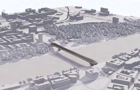
Set within the European project for high-speed railway development Magistrale for Europe the proposal of the Bratislava Terminal aims to reimagine what infrastructure could look like through a more user-oriented, human-scaled approach.
The project looks to traditional, vernacular, utilitarian Slovak timber construction methods for inspiration, merging the domestic and familiar with the infrastructural and innovative to create a new architectural language. Working within the restrictive framework of Slovak legislation concerning the use of structural timber in civic buildings, the proposal aims to become a showcase of this possibility embodied by the unifying timber roof sitting over the entire proposed station and bridge.
As a large intervention into the city, it is both infrastructurally and socially transformative. It not only brings the railway closer to the city center, but also acts as an inter-mobility hub merging the railway, public transport network as well as pedestrian and cycle infrastructures. Bridging over the Danube it interconnects public circulations, elevating the active streetscape across both banks. The development will not only interconnect the disjoint capital city but will also aid in bringing it a step closer to western Europe.
LUDKA MAJERNIKOVA YEAR
4
Y4 LM
I. ARTEFACT ANALYSIS
SEMESTER I. STUDY OF TIMBER CONSTRUCTION
VERNACULAR TIMBER CONSTRUCTION IN SLOVAKIA
VERNACULAR TIMBER CONSTRUCTION IN SLOVAKIA
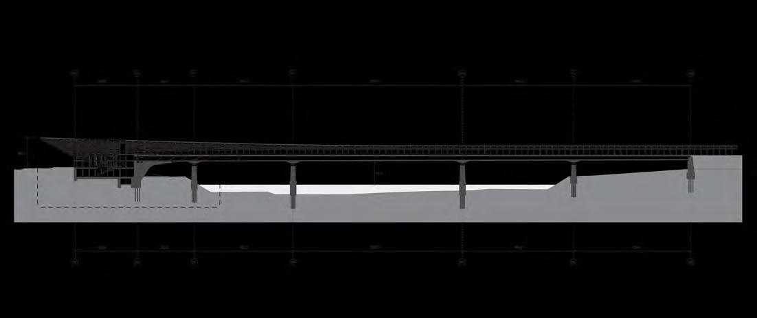
Historically located at the center of changing spheres of influence, traditional Slovak construction methods were greatly influenced by, and became a fusion of Slavic, Eastern-European, Germanic trends. The case study is an archetypal log house found across central and eastern Slovakia.
House scale
The scale of the houses was modest in length often dictated by the length of a trunk to avoid splicing of components. For this reason the houses expanded in length, adding smaller rooms for domestic or utilitarian use.
Ridge purlin
Gabled roof often clad with vertical planks
Timber roof rafter
Roof tie beam
Roof tie beam
Often times two logs spliced together depending on building depth
Often times two logs spliced together depending on building depth
Timber roof joist
Timber roof joist
Ridge purlin
Gabled roof often clad with vertical planks
Roof battens
Roof battens
Often notched directly onto roof rafters
Often notched directly onto roof rafters
Roof overhanging eaves
Roof overhanging eaves
Creates protected circulation around building perimeter and kept rain away from facade
Creates protected circulation around building perimeter and kept rain away from facade
Perimeter up-stand
Perimeter up-stand
Made of stone or masonry, the raised foundation was particularly useful in uneven, mountainous terrain
Made of stone or masonry, the raised foundation was particularly useful in uneven, mountainous terrain
SEMESTER 1 ANALYSIS: VERNACULAR TIMBER CONSTRUCTION IN SLOVAKIA
5m Bedroom Kitchen Storage 2.5m 4m
SEMESTER 1 ANALYSIS: VERNACULAR TIMBER CONSTRUCTION IN SLOVAKIA
DESIGN PORTFOLIO | BRATISLAVA TERMINAL
Interlocking shingles
Most often hand hewn from larch or spruce, in Slovak šindeľ
Roof truss post
Timber plank flooring
Roof edge beam sill
Interlocking notch connection on external walls corner
Timber floor joists
Often sat directly on rammed earth with an air gap acting as insulation
Roof beam notch
Beams directly attach onto external wall elements by notching, increasing the stability of the interlocking frame
Hand hewn logs
Main walls most often from softwood like spruce, hand hewn into rectangular profiles or in older houses left round. Gaps between logs were stuffed with moss or straw to help with thermal performance.
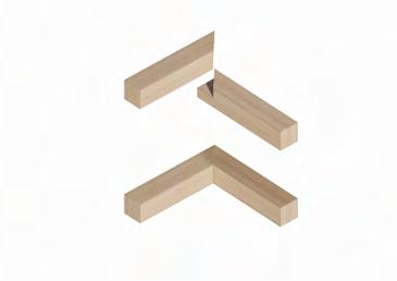
Roof corner
Edge beams joined by half lap or cross lap connection
Roof to wall connection
Wall logs extend outwards and interlock creating a bracket system supporting the roof edge beams
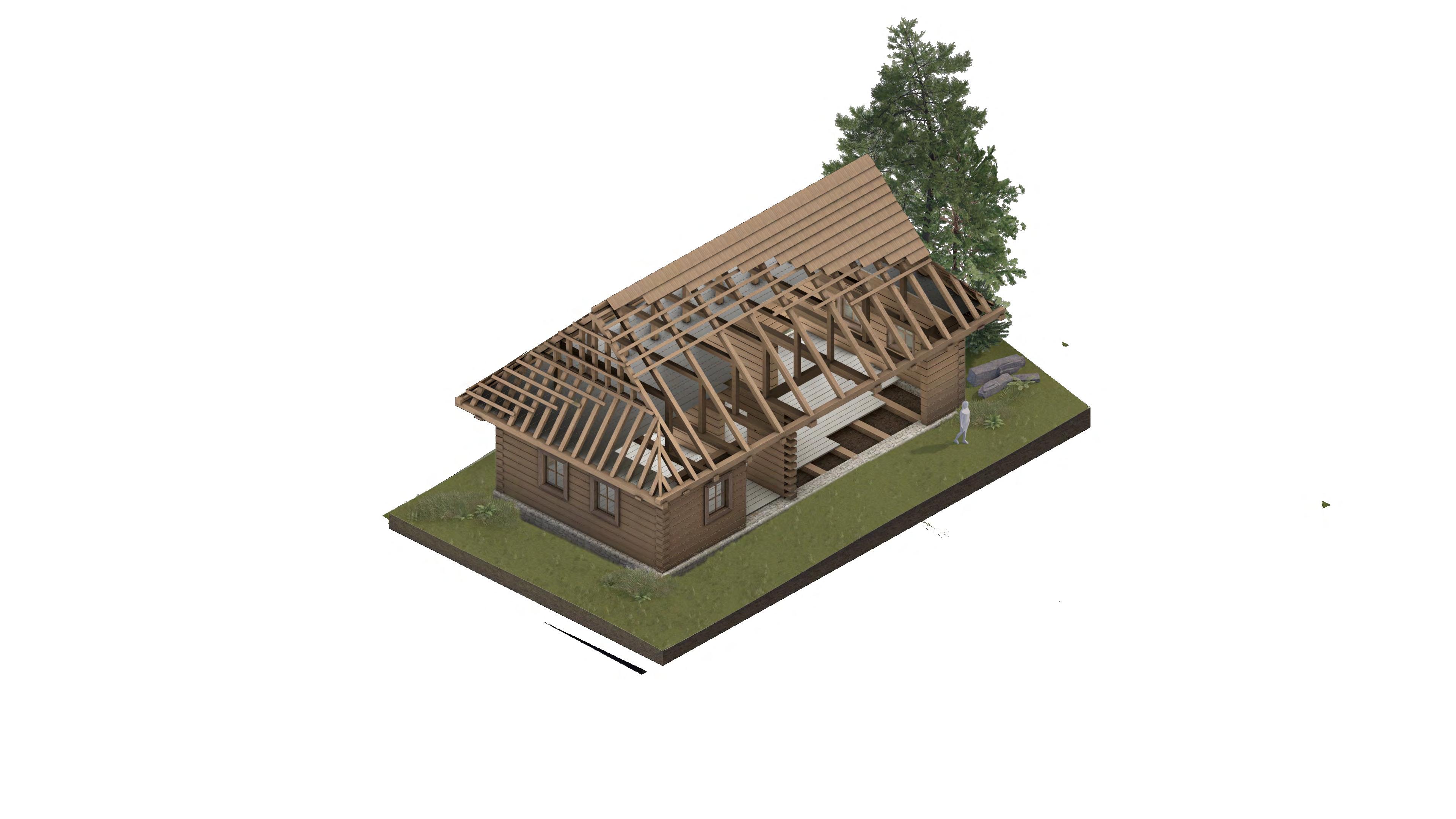
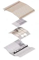
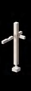
STACKING OF STRUCTURE
STACKING OF STRUCTURE
CORNER CONDITION
CORNER CONDITION
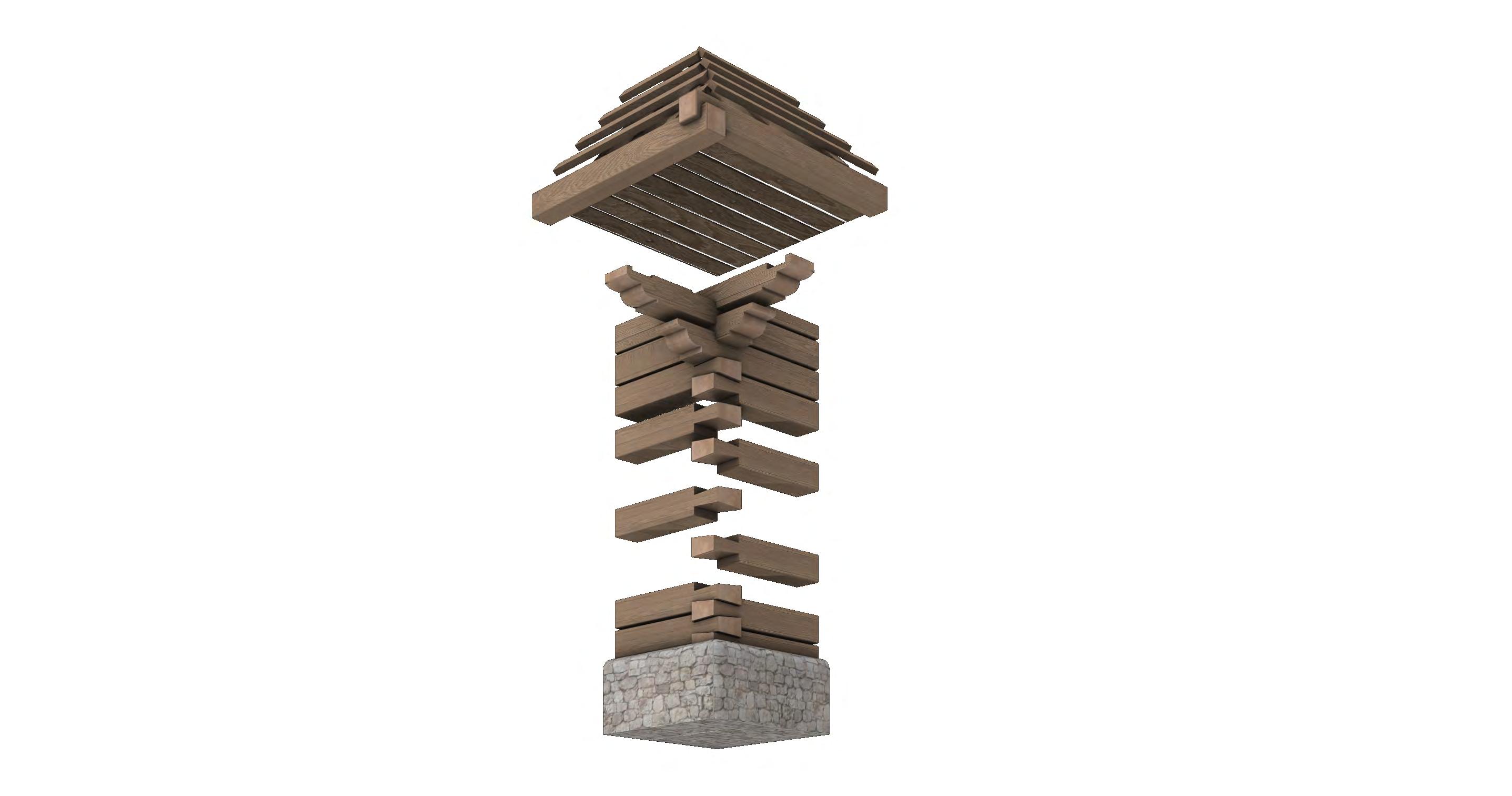
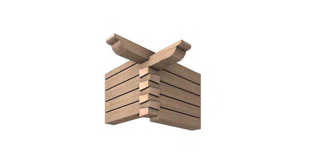
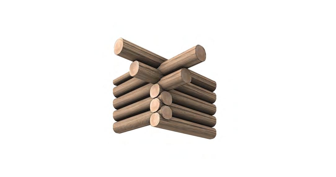
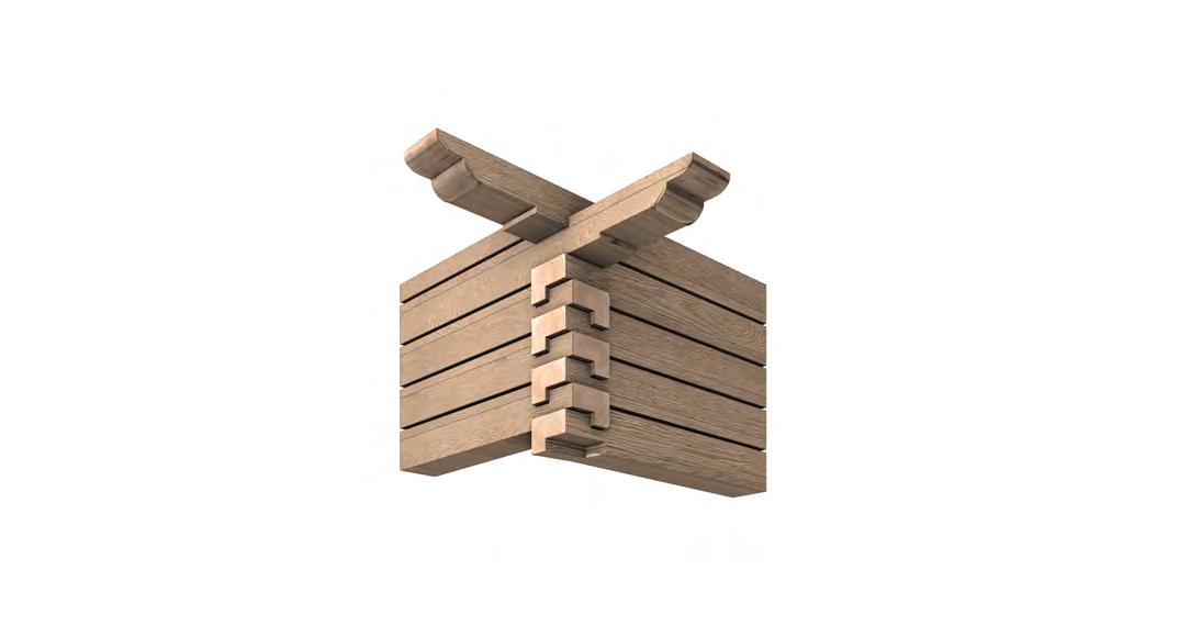
The roof edge beams overlap in roof corners, joined by cross lap connections allowing them to protrude. They are supported by the timber bracketry composed of extended wall logs towards the top of the walls. The stepping varies from house to house but most typically consist of four beams. These are typically also connected by cross lap joints to allow for protrusions. The base logs of the wall structure are anchored into the stone up-stand.
The roof edge beams overlap in roof corners, joined by cross lap connections allowing them to protrude. They are supported by the timber bracketry composed of extended wall logs towards the top of the walls. The stepping varies from house to house but most typically consist of four beams. These are typically also connected by cross lap joints to allow for protrusions. The base logs of the wall structure are anchored into the stone up-stand.
I. Roof edge beams
Beams overlap in roof corners, joined by cross lap connection allowing them to protrude
II. Roof to wall connection
Wall logs extend outwards, interlock and stack up with a cross lap creating a bracket system which supports the roof edge beams
III. Perimeter up-stand
The base logs of the wall structure are anchored into the stone up-stand with timber members.
DESIGN PORTFOLIO | BRATISLAVA TERMINAL ARTEFACT ANALYSIS | FRAGMENT EXPERIMENTATION
DESIGN
| BRATISLAVA TERMINAL ARTEFACT ANALYSIS | FRAGMENT EXPERIMENTATION
PORTFOLIO
II.
I.
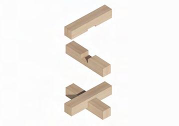
CROSS
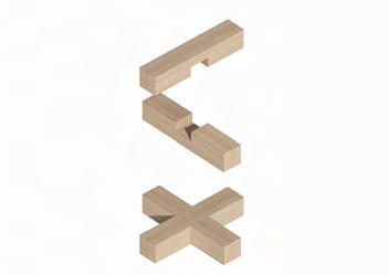
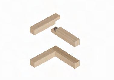
LAP CONNECTIONS
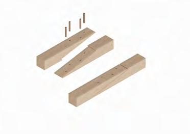
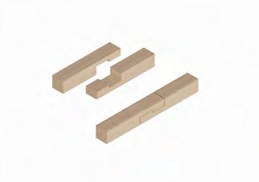
SPLICE CONNECTIONS
Splices are used to join two timber members end-to-end to span a greater length than the individual piece of timber spans. This offers a grain face to grain face connection. Lap connections are used when members meet perpendicularly and have to overlap to a flush corner connection or cross over and continue spanning.


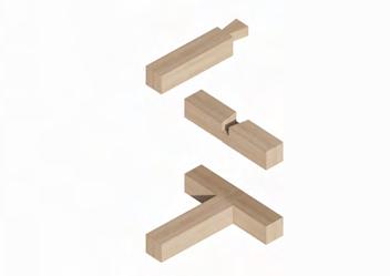
 I. Half-Lap
III. Under Squinted Half-Lap
V. Under Squinted Stop Splayed with Table
II. Half-Lap With Table
IV. Under Squinted Stop Splayed Half-Lap II. Stop Bladed with Cogs
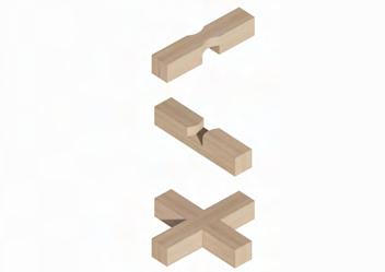
I. Flush Cross-Lap II. Cross-Lap III. Curved Cross-Lap
IV. Mitered Half-Lap
V. Dove-Tail Half-Lap
VI. Half-Lap
I. Half-Lap
III. Under Squinted Half-Lap
V. Under Squinted Stop Splayed with Table
II. Half-Lap With Table
IV. Under Squinted Stop Splayed Half-Lap II. Stop Bladed with Cogs
I. Flush Cross-Lap II. Cross-Lap III. Curved Cross-Lap
IV. Mitered Half-Lap
V. Dove-Tail Half-Lap
VI. Half-Lap
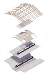
VOLUMETRIC STACKING: SCALING OF CORNER CONDITION
VOLUMETRIC STACKING: SCALING OF CORNER CONDITION
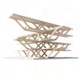
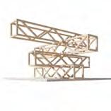
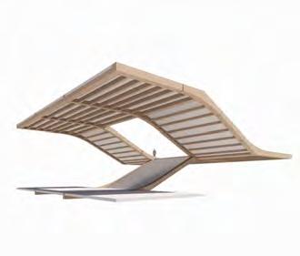
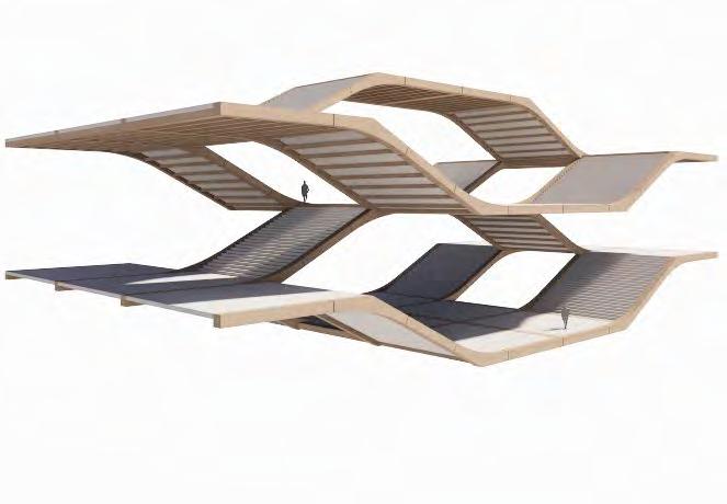
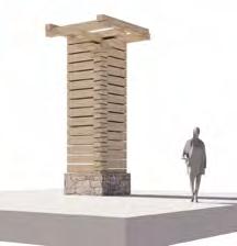
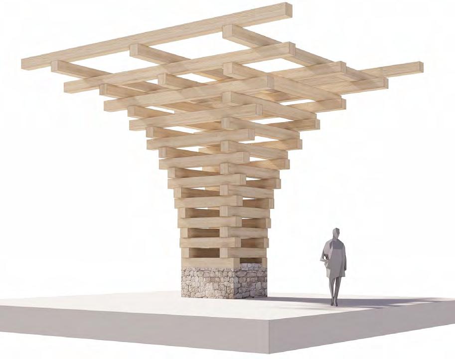
Scaling the analysed cantilevering corner condition to a full building level allows for a study of the potential spatial opportunities the system offers. Due to the nature of the material chosen the structural principles and tectonic change significantly, pushing the direction towards more contemporary timber solutions such as lamination in glulam and baubuche solutions.
Scaling the analysed cantilevering corner condition to a full building level allows for a study of the potential spatial opportunities the system offers. Due to the nature of the material chosen the structural principles and tectonic change significantly, pushing the direction towards more contemporary timber solutions such as lamination in glulam and baubuche solutions.

I. Scaled up notch corner condition II. Simple truss construction III. Fused horizontal and vertical structure
DESIGN
| BRATISLAVA TERMINAL
This condition under-pass direction tree circulation OVERPASS SEMESTER 1 ARTEFACT ANALYSIS STACKING OF VOLUMES STACKING I. Scaled up notch corner condition II. Simple truss construction III. Fused horizontal and vertical structure
PORTFOLIO
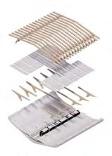
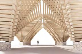
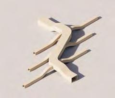
MULTI-DIRECTIONAL
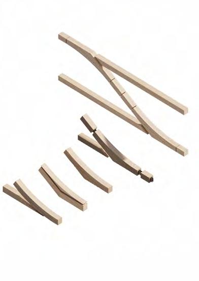
IV. Maintaining dynamic directionality I. Creation of single component from curved lamellas to achieve desired shape II. Splitting component into core of without curvature and additional stepped curved lamellas III. Fusion of horizontal beam structure with slanting components while maintaining the curvature of the diagonal member DESIGN
| BRATISLAVA
This under-pass direction tree OVERPASS SEMESTER 1 ARTEFACT ANALYSIS STACKING OF VOLUMES STACKING
PORTFOLIO
TERMINAL MULTI-DIRECTIONAL
MULTI-DIRECTIONAL OVERPASSOVERPASS - UNDERPASS NODE
OVERPASS STUDY: MULTI-LEVEL CIRCULATION
This condition looks at the possibility of simultaneously being able to under-pass and over-pass from the same location. Staggering the staircase direction can allow for easy access to both types of circulations, connecting tree circulation corridors at different levels.
MULTI-LEVEL CIRCULATION NODE
condition vertical structure directionality single curved achieve component without and stepped lamellas horizontal structure with components maintaining of the member
STACKING OF CIRCULATION
II. BRATISLAVA TERMINAL
CITY CONTEXT + ANALYSIS
ORIENT / EAST-MEDITERRANEAN LINK
BALTIC-ADRIATIC LINK
RHINE-DANUBE LINK
TRANS EUROPEAN TRANSPORT NETWORK
Built on the crossroads of historic international trade routes and the river Danube, Bratislava has always held a strategic position in inter-continental trade. Today it sits on the crossroad of three Trans European Transport Networks - rail and river - directly connecting it to the Adriatic, Black, Baltic and North Seas.
Frankfurt Hamburg Strasbourg Kraków Brno Warszawa Budapest Bratislava Žilina Wien Salzburg Praha München Berlin Bremen Leipzig Mannheim Venezia Bologna Ancona Nürnberg Dresden Wrocław Katowice Poznań Stuttgart Bucureşti Sofia Braşov Arad Thessaloníki Athína Pátra Graz Erfurt Linz Szczecin Lübeck Bratislava Kúty AUSTRIA DESIGN PORTFOLIO | BRATISLAVA TERMINAL Currently 80-100 railway and Central SLOVAKIA For 2022: 40% Iron Ore 13% Metals 12% Coal 9% Stone (Building 8% Petroleum 7% Timber 6% Chemical 5% Other INDUSTRY RAILWAY CARGO TRANSPORT PROJECT NARRATIVE: WIDER CONTEXT
RAILWAY CONNECTIVITY
10-70 km/h
71-100 km/h
101-120 km/h
120-160 km/h
INDUSTRY + IMPACT ON RAILWAY DEVELOPMENT
RAIL TYPES
CARGO TRANSPORT DIVISION
For 2022:
40% Iron Ore
13% Metals
12% Coal
9% Stone (Building material)
8% Petroleum products
7% Timber
6% Chemical products
5% Other
CHEMICAL & PETROLEUM PRODUCTS IRON ORE COAL TIMBER
SLOVAKIA RAIL DEVELOPMENT + OVERVIEW
TRANSITION OF GAUGES
Bordering the Ukraine makes eastern Slovakia a strategic transit zone for all goods transported further east as well as incoming imports moving further west. For this reason both the narrow and wide gauges can be found in this region.
Currently there are no high-speed railway tracks in Slovakia, the average speed being only around 80-100 km/h, with few 160 km/h segments. The aim should be to link to the existing high-speed railway links in close proximity, to become a part of the network much enjoyed by the rest of Wester and Central Europe.
RAILWAY LINES MID-SPEED RAILWAY MISSING HIGH-SPEED LINK WIDE-GAUGE RAIL TRANSITION TO UE
Bucureşti Braşov Thessaloníki Athína Bratislava Komárno Čierna nad Tisou Muszyna Svrčinovec Kúty Žilina Košice Bratislava Komárno Čierna nad Tisou Muszyna Svrčinovec Kúty Žilina Košice Bratislava Komárno Čierna nad Tisou Muszyna Svrčinovec Kúty Žilina Košice HUNGARY 30 MINUTES 60 MINUTES 90 MINUTES 180 MINUTES 240 MINUTES UKRAINE POLAND CZECHIA AUSTRIA
ICE / ECE DEUTSCHE BAHN
RAILJET - OBB, DB, ČD PARTNERSHIP
EXPRESS INTERCITY PREMIUM (PKP)
MAGISTRALE FOR EUROPE
MAGISTRALE FOR EUROPE
Currently there are no high-speed railway tracks in Slovakia, the average speed being only around 80100 km/h, with few 160 km/h segments. The aim should be to link to the existing high-speed railway links in close proximity, to become a part of the network much enjoyed by the rest of Wester and Central Europe. The EU project Magistrale for Europe - high-speed rail network linking Paris to Bratislava - will bring major development of Bratislava and its economy by bringing it closer to the West.
Frankfurt Köln Dortmund Bremen Liège Hannover Hamburg Berlin Leipzig Brussel Paris Milano Zürich Mannheim Innsbruck Venezia Dresden Wrocław Katowice Kraków Brno Praha Warszawa Stuttgart München Salzburg Graz Budapest Bratislava Wien Gdańsk Erfurt Linz Duisburg Amsterdam Rostock Lübeck
Dublin London Amsterdam Paris Luxembourg Brussels Lisbon Madrid Bern DESIGN PORTFOLIO | BRATISLAVA TERMINAL PROJECT NARRATIVE: WIDER CONTEXT
EUROVELO CYCLE-PATHS
Sarajevo
Bern Bratislava currently sits on the intersection of several trans-european Eurovelo cycle-paths. Boosting cycle infrastructure in the city will so grow the european cycle infrastructure along the Danube, strengthening the link between the cycle paths connecting Bratislava to Vienna, Budapest and beyond.
Dublin London Amsterdam Oslo Copenhagen Helsinki Tallinn Stockholm Riga Moscow Minsk Kiev Warsaw Vilnius Berlin Prague Paris Luxembourg Brussels Rome Bratislava Vienna Budapest Liubljana Zagreb Sarajevo Belgrade Prisitina Skopje Sofia Tirana Bucarest Athens Podgorica Lisbon Madrid Bern Amsterdam Oslo Copenhagen Helsinki Tallinn Stockholm Riga Moscow Minsk Kiev Warsaw Vilnius Berlin Prague Paris Luxembourg Brussels Rome
Vienna Budapest
Bratislava
Liubljana Zagreb
Belgrade
Skopje Sofia
Bucarest Athens
Prisitina
Tirana
Podgorica
CZECHIA & AUSTRIA
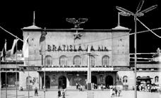
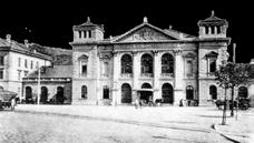
FIRST STATION BUILDING
BRATISLAVACENTRAL STATION
EAST SLOVAKIA & HUNGARY
PUBLIC TRANSPORT STATION
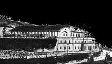
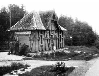
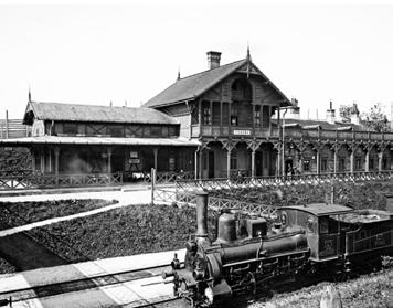
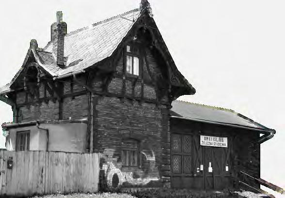
RAILWAY STATION STYLE 19TH CENTURY TYPOLOGY
This half-timbered architectural style came to the slovak region under the Austro-Hungarian empire in the late 19th century. Under the influence of existing 19th century germanic industrial styles in Slovakia the half-timbered style it blended into a new style, linked with railway buildings and leisure centers from this period.
A unified style of railway architecture on the oldest railway links in Slovakia is however primarily due to the influence of the Austian National Railway Service (Österreichische Staatseisenbahngesellschaft – StEG) which funded most of the railway construction in Slovakia at the time.
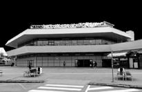
The current building lacks the capacity, connectivity, public space and services a station of an EU capital city should offer. The station sits in little valley at the feet of the Kamzik mountain (first peak of the Small Carpathians) and the Castle hill. The terrain conditions make any expansion or modernisaton attempts very difficult and costly.
TRAIN STATION PRESENTATION 01 26/04/2021
Štrba, 1871
TRANSPORT MUSEUM
Tatranská Štrba,
DESIGN PORTFOLIO | BRATISLAVA TERMINAL
STATION DEVELOPMENT: SYMBOL OF POLITICAL REGIMES Štrba, Traditional Commonly stations in Slovakia TRADITIONAL 1871 1848 1940 1989 PROJECT NARRATIVE: CITY CONTEXT
STATION
STYLE TYPOLOGY
style came to the slovak empire in the late 19th existing 19th century germanic half-timbered style it blended railway buildings and leisure
architecture on the oldest railway primarily due to the influence Service (Österreichische which funded most of the time.
STYLE TYPOLOGY
to the slovak in the late 19th century germanic style it blended buildings and leisure
oldest railway the influence (Österreichische funded most of
RAILWAY STATION STYLE 19TH CENTURY TYPOLOGY
This half-timbered architectural style came to the slovak region under the Austro-Hungarian empire in the late 19th century. Under the influence of existing 19th century germanic industrial styles in Slovakia the half-timbered style it blended into a new style, linked with railway buildings and leisure centers from this period.
A unified style of railway architecture on the oldest railway links in Slovakia is however primarily due to the influence of the Austian National Railway Service (Österreichische Staatseisenbahngesellschaft – StEG) which funded most of the railway construction in Slovakia at the time.
Štrba, 1871
TRADITIONAL STATION DESIGN - PUBLIC RAILWAY
TRAIN STATION PRESENTATION 01 26/04/2021
Traditional Austro-Hungarian Railway Secession style inspired by Germanic Alpine architecture. Commonly used during the late 19th and early20th century in first railway holiday destinations or simply stations dedicated for public use. The common traits were external timber framing, uncommon otherwise in Slovakia - so clearly linking to the building’s function.
 Stará Kremnička, 1872
Štrba, 1871
Trenčín, 1883
Bjarke Ingels Group ESET Campus
Nové Štrbské Pleso, 1896
Stará Kremnička, 1872
Tatranská Lomnica, 1895
Plešivec, 1896
Štrba, 1871
Trenčín, 1883
Nové Štrbské Pleso,
Stará Kremnička, Tatranská Lomnica, 1895
Štrba, 1871
Nové Štrbské Pleso, 1896
Tatranská Lomnica, 1895
Stará Kremnička, 1872
Štrba, 1871
Trenčín, 1883
Bjarke Ingels Group ESET Campus
Nové Štrbské Pleso, 1896
Stará Kremnička, 1872
Tatranská Lomnica, 1895
Plešivec, 1896
Štrba, 1871
Trenčín, 1883
Nové Štrbské Pleso,
Stará Kremnička, Tatranská Lomnica, 1895
Štrba, 1871
Nové Štrbské Pleso, 1896
Tatranská Lomnica, 1895
EXPANSION ISSUES
EXPANSION ISSUES Lamač Tunnel
EXISTING STATIONS: PEOPLE: 60,000 - 90,000 Daily PUBLIC TRAINS: 125 - 130 Daily PLATFORMS: 6 Platforms 10 edges TRACKS Transport tracks: 31 Manipulation tracks: 16 Side-tracks: 23 Other: 6
DESIGN PORTFOLIO | BRATISLAVA TERMINAL
Transport Museum 1. 6.
STATION BUILDING
VIENNA, CZ EAST SLOVAKIA
2. 3. 4. 5.
Aside from its personal transport role The Central Station is home to the main railway depot, maintenance tracks and cargo manipulation tracks. Due to this, the efficiency of personal transport is compromised as the station struggles to cope with the capacity. Within the context of 2030 EU targets more cargo and more people need to be transported via railway making it’s expansion and / or functional division essential.
Aside from its personal transport role The Central Station is home to the main railway depot, maintenance tracks and cargo manipulation tracks. Due to this, the efficiency of personal transport is compromised as the station struggles to cope with the capacity.
Within the context of 2030 EU targets more cargo and more people need to be transported via railway making it’s expansion and / or functional division essential.
Personal Transport tracks Cargo / Train manipulation tracks Side-tracks PEOPLE: 60,000 - 90,000 Daily PUBLIC TRAINS: 125 - 130 Daily PLATFORMS: 6 Platforms 10 edges TRACKS Transport tracks: 31 Manipulation tracks: 16 Side-tracks: 23 Other: 6 Lamač Tunnel VIENNA, CZ EAST SLOVAKIA STATION BUILDING Transport Museum 1. 6. 2. 3. 4. 5.
DESIGN PORTFOLIO | BRATISLAVA TERMINAL
BRATISLAVA CENTRAL STATION Personal Transport tracks Cargo / Train manipulation tracks Side-tracks
BRATISLAVA CENTRAL STATION
EXISTING STATIONS:
BRATISLAVA PETRŽALKA
Due to it’s peripheral location the station has historically relied on Cargo transport rather than public transport. Connected to several industrial areas in the city, the majority of the tracks are dedicated to cargo. Passenger transport is reliant on the OBB high-speed track extension to the station connecting to Vienna.
Personal Transport tracks Cargo / Train manipulation tracks Side-tracks PEOPLE: ~40,000 Daily PUBLIC TRAINS: 76 Daily PLATFORMS: 2 Platforms 3 edges TRACKS Transport tracks: 12 Side-tracks: 4 Other: 1
cargo manipulation 1.
Tracks for
2.
INDUSTRIAL PARK MATADOR AUSTRIA HUNGARY STATION BUILDING
CENTRAL STATION, INDUSTRIAL PARK SLOVNAFT, BA PORT
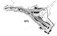
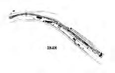
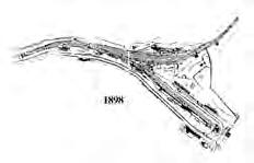
DISJOINT INFRASTRUCTURE
Due to the geographic condition of the city, two railway loops converge towards the historic city center from the north and south banks of the Danube.
The northern railway network first connected Bratislava to Vienna and later Budapest. The southern connection had room to expand not being restrained by mountainous terrain, currently serves as a crucial international link for cargo and industrial goods’ transport. It is also the link towards the European high-speed railway.
DESIGN PORTFOLIO | BRATISLAVA TERMINAL
PROJECT NARRATIVE: CITY CONTEXT
GEOGRAPHICAL PLACEMENT
CZECH REPUBLIC & AUSTRIA EAST SLOVAKIA & HUNGARY
The main railway station of Bratislava is situated just north of the city center at the feet of the Carpathian mountains. Given the topographical conditions the location is strategic, sitting right in the only mountain pass through the Carpathians in Bratislava - connecting the ancient trade routes of the Danube river, Amber Road and connection to Prague.
DESIGN PORTFOLIO | BRATISLAVA TERMINAL CITY CONTEXT: INTERMOBILITY: Socialist 1970s construction CURRENT Further increasing public into cargo INTEGRATED
BRATISLAVA METRO PROPOSAL CURRENT TRAM LINE
Socialist plans for Bratislava Metro from the 1970s that never came to be realized even though construction began.
Socialist plans for Bratislava Metro from the 1970s that never came to be realized even though construction began.
INTEGRATED PUBLIC TRANSPORT: INTERMOBILITY
Further deepening the agenda for an integrated public transport system network, increasing intermobility with particular focus on the revival of the railway as means of public transport. The proposed link would furthermore shift the public railway station into the heart of the city center while leaving the two peripheral stations dedicated for cargo transport.
DESIGN PORTFOLIO | BRATISLAVA TERMINAL SITE ANALYSIS: AREAS OF INTEREST
1.
2.
3.
4.5.
8.
10.
0m 100m 200m 400m
11. 12.
1. Bratislava castle
2. National Gallery
3. National Museum
4. University
10.
11.
12.
DESIGN PORTFOLIO | BRATISLAVA TERMINAL SITE ANALYSIS: AREAS OF INTEREST
5. Galley Umelka 6. National Theater 7. Commercial hub
8. Theater Arena 9. Central Bus Station
Historic park
Cultural / market venue
Cathedral Floodplain Forest Flood Zone Parks Areas of Development
1.
2.
3.
4.5.
8.
10.
0m 100m 200m 400m
11. 12.
1. Bratislava castle
2. National Gallery
3. National Museum
4. University
5. Galley Umelka
6. National Theater 7. Commercial hub 8. Theater Arena 9. Central Bus Station 10. Historic park 11. Cultural / market venue 12. Cathedral Floodplain Forest Flood Zone Parks Areas of Development
6.
9.
7.
Mapping mobility and
DESIGN PORTFOLIO | BRATISLAVA TERMINAL Cycle Pedestrian Public JAN AVERAGE MONTHLY TEMPERATURES + PRECIPITATION PRECIPITATION AVERAGE DAILY MIN COLD NIGHTS AVERAGE DAILY MAX HOT DAYS -10°C -20°C 0°C -1°C 4°C 10°C 17°C 22°C 2°C 6°C 11°C 15°C 27°C 15°C 12°C 9°C 5°C 1°C -2°C -2°C 27°C 24°C 21°C 16°C 10°C 5°C 3°C 10°C 20°C 30°C 40°C 100mm 50mm 0mm 25mm 75mm FEBMARAPR MAY JUNJUL AUG SEPOCT NOV DEC >1 >5 >12 >19 >28 >38 >50 >61 km/h N NNE NE ENE E ESE SE SSE S SSW SW WSW W WNW NW NNW 0 500 1000 1500 DANUBE STANDARD LEVELS 50 YEAR FLOOD LEVELS 100 YEAR FLOOD LEVELS FLOODPLAIN FOREST SITE SITE SELECTION + STRATEGY DEFINITION
SITE STRATEGY: CONSTRAINTS + OPPORTUNITIES
SITE STRATEGY: CONSTRAINTS + OPPORTUNITIES
Mapping of possible site constraints and opportunities with the focus on mobility and circulation: pedestrian, cyclist, public transport, river transport and railway as well as natural conditions such as greenery and the flood zone
SITE STRATEGY: CONSTRAINTS + OPPORTUNITIES
Mapping of possible site constraints and opportunities with the focus on mobility and circulation: pedestrian, cyclist, public transport, river transport and railway as well as natural conditions such as greenery and the flood zone
Mapping of possible site constraints and opportunities with the focus on mobility and circulation: pedestrian, cyclist, public transport, river transport and railway as well as natural conditions such as greenery and the flood zone
FLOOD ZONE TRANSPORT CORRIDOR CONTEXT BUILDING HEIGHT CLEAR HEIGHT FOR BOATS SAD JANKA KRALA PARK FLOODPLAIN FOREST CYCLE PATH CYCLE PATH RIVER PROMENADE RIVER PROMENADE RIVERSIDE MAIN ROAD TRAMLINE GALLERY UMELKA THEATER ARENA FLOOD ZONE TRANSPORT CORRIDOR CONTEXT BUILDING HEIGHT CLEAR HEIGHT FOR BOATS SAD JANKA KRALA PARK FLOODPLAIN FOREST CYCLE PATH CYCLE PATH RIVER PROMENADE RIVER PROMENADE RIVERSIDE MAIN ROAD TRAMLINE GALLERY UMELKA THEATER ARENA Danube transport corridor Flood Barrier Zone Floodplain forest Historic Park
path
Public Transport stops MIN MAX
Cycle
Pedestrian path
FLOOD ZONE TRANSPORT CORRIDOR CONTEXT BUILDING HEIGHT CLEAR HEIGHT FOR BOATS SAD JANKA KRALA PARK FLOODPLAIN FOREST CYCLE PATH CYCLE PATH RIVER PROMENADE RIVER PROMENADE RIVERSIDE MAIN ROAD TRAMLINE GALLERY UMELKA THEATER ARENA FLOOD ZONE TRANSPORT CORRIDOR CONTEXT BUILDING HEIGHT CLEAR HEIGHT FOR BOATS SAD JANKA KRALA PARK FLOODPLAIN FOREST CYCLE PATH CYCLE PATH RIVER PROMENADE RIVER PROMENADE RIVERSIDE MAIN ROAD TRAMLINE GALLERY UMELKA THEATER ARENA Danube transport corridor Flood Barrier Zone Floodplain forest Historic Park
Pedestrian path Public Transport stops MIN MAX
Cycle path
FLOOD ZONE TRANSPORT CORRIDOR CONTEXT BUILDING HEIGHT CLEAR HEIGHT FOR BOATS SAD JANKA KRALA PARK FLOODPLAIN FOREST CYCLE PATH CYCLE PATH RIVER PROMENADE RIVER PROMENADE RIVERSIDE MAIN ROAD TRAMLINE GALLERY UMELKA THEATER ARENA FLOOD ZONE TRANSPORT CORRIDOR CONTEXT BUILDING HEIGHT CLEAR HEIGHT FOR BOATS SAD JANKA KRALA PARK FLOODPLAIN FOREST CYCLE PATH CYCLE PATH RIVER PROMENADE RIVER PROMENADE RIVERSIDE MAIN ROAD TRAMLINE GALLERY UMELKA THEATER ARENA Danube transport corridor Flood Barrier Zone Floodplain forest Historic Park
path Pedestrian path Public Transport stops MIN MAX
Cycle
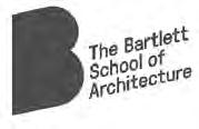
III. THE BRIDGE STATION
DESIGN DEVELOPMENT
P2 P1 A1 F1 137.0 18.0 24.0 80.0 45.0 50.0 P2 P1 A1 F1 137.0 80.0 45.0 50.0
P3 P4 A2 18.0 90.0 95.0 P3 P4 A2 90.0 95.0
BRATISLAVA
MASSING STRATEGY: BUILDING GENESIS
MASSING STRATEGY: BUILDING GENESIS
RESPONSE TO CONSTRAINTS
EXISTING + REUSE
Dismantling of existing bridge structure and maintaining existing masonry piers.
Dismantling of existing bridge structure and maintaining existing masonry piers.
HIERARCHY / DIRECTIONALITY
Adjusting mass to reflect the hierarchy of the two river banks and dominant directionality of both programme and circulation flows towards the historic north bank of Bratislava.
Adjusting mass to reflect the hierarchy of the two river banks and dominant directionality of both programme and circulation flows towards the historic north bank of Bratislava.
Adjusting massing to surrounding building heights, minimum boats, pedestrian and cycle paths along the river bank
Adjusting massing to surrounding building boats, pedestrian and cycle paths along the
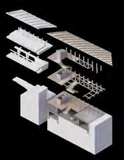
CITY STRATA: MATERIAL LAYERING
Adjusting mass to reflect the hierarchy of the two river banks directionality of both programme and circulation flows towards bank of Bratislava.
Adjusting mass to reflect the hierarchy of the directionality of both programme and circulation bank of Bratislava.
MASSING
DESIGN PORTFOLIO | BRATISLAVA TERMINAL DESIGN DEVELOPMENT:
STRATEGY
TRANSPORTCORRIDOR FLOODPLAIN PROMENADE EUROVELO DESIGN
MASSING STRATEGY
PORTFOLIO |
TERMINAL DESIGN DEVELOPMENT:
heights, minimum clear height for river the river bank and other constraints.
PROGRAMME REQUIREMENTS
Programme sizing and placement on site. Simple division between terminal hall, platforms, promenade and railway positioning. Respecting all site constraints.
LAYERING
the two river banks and dominant circulation flows towards the historic north
ACTIVATION + CIRCULATION

Addition of perimeter promenades as an extension of the public realm around. The result is a seamless merging of the urban realm with the bridge programme and elevating the existing public infrastructures.
FLOODPLAIN PROMENADE PUBLIC TRANSPORT
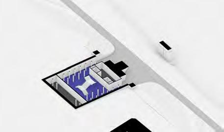
ENTRANCE
ENTRANCE
CYCHLE-PATH
TERMINAL
TERMINAL
ENCLOSURE
CYCLE-STATIONS PLATFORMS
PROMENADE
PROGRAMME REQUIREMENTS + ORGANIZATION
PROGRAMME REQUIREMENTS + ORGANIZATION
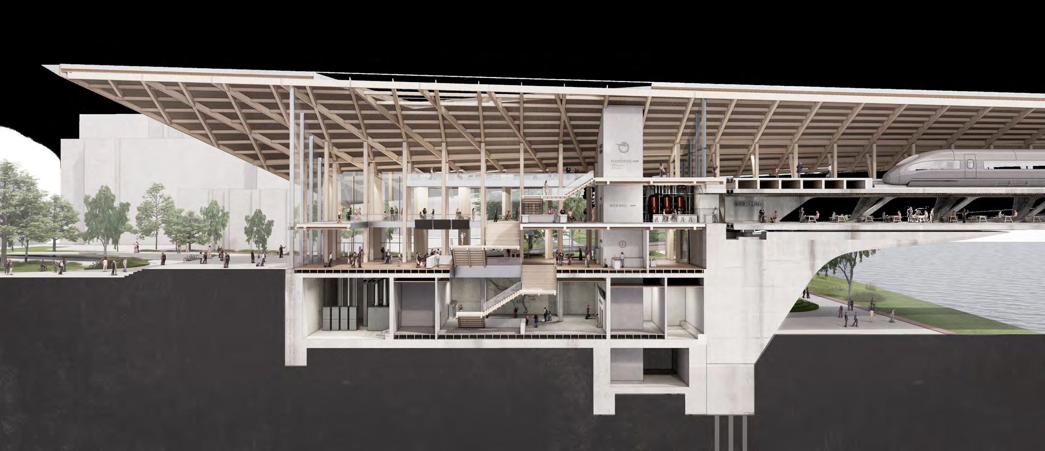
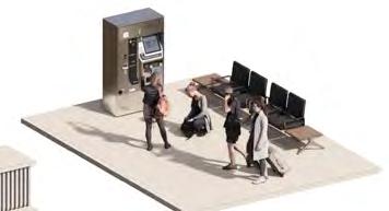
The station programme is primarily divided across levels to create a direct, userfriendly and fast route from the station concourse to the bridge platforms without being affected by supporting programme on the perimeter.
The station programme is primarily divided across levels to create a direct, userfriendly and fast route from the station concourse to the bridge platforms without being affected by supporting programme on the perimeter.
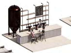
INFORMATION BAR AREA TERMINAL SEATING BEER HALL BRIDGE SEATING +BAR AREA SUPPORT (WC’s) SUPPORT (WC’s) SUPPORT (WC’s) TICKET PURCHASE
AREAS CONCOURSE
WAITING
HALL
EXT.
INT.
CYCLE-PATH
PROMENADE CYCHLE-PATH
BRIDGE
+ STORAGE
+ STORAGE DESIGN PORTFOLIO | BRATISLAVA TERMINAL TERMINAL HALL BEER HALL WAITING PLATFORMS CYCLE PATH BEER HALL MEP BOH
LINE
CYCLE-STATIONS PLATFORMS
B.O.H.
B.O.H.
ENCLOSURE
ZONE
LINE
ENCLOSURE
INFORMATION TERMINAL SEATING BEER HALL BRIDGE SEATING +BAR AREA (WC’s)
SUPPORT (WC’s) TICKET PURCHASE WAITING AREAS CONCOURSE
PROGRAMME ZONING STRATEGY
SUPPORT (WC’s)
HALL
CYCLE-PATH EXT.
INT.
BRIDGE
+ STORAGE
B.O.H.
DESIGN PORTFOLIO | BRATISLAVA TERMINAL TERMINAL HALL BEER HALL WAITING PLATFORMS CYCLE PATH BEER HALL MEP BOH
B.O.H. + STORAGE
LINE
LINE
ZONE ENCLOSURE
PROGRAMME
route activation B01 L01
Division
PROGRAMME ZONING STRATEGY
PROGRAMME LAYERING
Division of programme across levels in a way to maintain direct route for masses of rushing passengers, while having perimeter activation at all other times
Terminal concourse
Platforms
Beer
Public
Cycle-path B.O.H. MEP areas
SUPPORT + BOH TICKETS HALL MEP ENTRANCE ZONE SUPPORT + BOH TICKETS + WAITING AREAS ENTRANCE HALL SUPPORT + BOH BEER HALL + WAITING AREAS ENCLOSED CYCLE-PATH BEER HALL WAITING AREAS PUBLIC PROMENADE PLATFORMS
B01
RIVERSIDE ENTRANCE GF - MAIN ENTRANCE HALL L01 - BEER HALL L02 - WAITING AREAS + PLATFORMS
-
Hall
Promenade
BRIDGES OF BRATISLAVA
BRIDGES OF BRATISLAVA
BRIDGES OF BRATISLAVA
STRUCTURAL RE-USE Pier Caps will have built upon to increase clear height under the
BRIDGE OF THE SLOVAK NATIONAL UPRISING
BRIDGE OF THE SLOVAK NATIONAL UPRISING
BRIDGE OF THE SLOVAK NATIONAL UPRISING
Cable-stayed bridge with fan system, steel & concrete frame box frame
MASSING
Cable-stayed bridge with fan system, steel & concrete frame box frame
Cable-stayed bridge with fan system, steel & concrete frame box frame
Reinforced concrete dation. Typical cross-section provides minimal resistance water flow
BRIDGE OF THE SLOVAK NATIONAL UPRISING
BRIDGE OF THE SLOVAK NATIONAL UPRISING
BRIDGE OF THE SLOVAK NATIONAL UPRISING
Steel frame through truss bridge 460m long, 32m wide, 10m tall
Steel frame through truss bridge 460m long, 32m wide, 10m tall
Steel frame through truss bridge 460m long, 32m wide, 10m tall
APOLLO BRIDGE
APOLLO BRIDGE
APOLLO BRIDGE
Tied-arch bridge with inclined hangers, steel & concrete frame
Tied-arch bridge with inclined hangers, steel & concrete frame
Tied-arch bridge with inclined hangers, steel & concrete frame
IDENTIFYING SUITABLE BRIDGE TYPE
IDENTIFYING SUITABLE BRIDGE
BEAM / GIRDER BRIDGE
BEAM / GIRDER BRIDGE
BEAM / GIRDER BRIDGE
Most suitable type for large spans without suspension, easy pre-fabrication, potentially two levels for linear programme
TERMINAL
IDENTIFYING SUITABLE BRIDGE TYPE
TYPE
Most suitable type for large spans without suspension, easy pre-fabrication, potentially two levels for linear programme
Most suitable type for large spans without suspension, easy pre-fabrication, potentially two levels for linear programme
CABLE-STAYED BRIDGE
BRIDGE
TIED-ARCH BRIDGE
430m 350m 840m 303m 54m 98.7m 82.6m 70.2m 51.5m 74.8m 50m ~20m 36m ~15m 85m 60m 240m 460m 32m 75.9m 75.6m 137m 107m 32.6m 430m 350m 840m 303m 54m 98.7m 82.6m 70.2m 51.5m 74.8m 50m ~20m 36m ~15m 85m 60m 240m 460m 32m 75.9m 75.6m 137m 107m 32.6m ~15m 430m 350m 840m 303m 54m 98.7m 82.6m 70.2m 51.5m 74.8m 50m ~20m 36m ~15m 85m 60m 240m 460m 32m 75.9m 75.6m 137m 107m 32.6m ~15m SUPER-STRUCTURE SUB-STRUCTURE BEAM BRIDGE TRUSS BRIDGE CANTILEVER BRIDGE ARCH BRIDGE SUSPENSION BRIDGE CABLE-STAYED BRIDGE BEAM BRIDGE TRUSS BRIDGE CANTILEVER BRIDGE ARCH BRIDGE SUSPENSION BRIDGE CABLE-STAYED BRIDGE BEAM BRIDGE TRUSS BRIDGE CANTILEVER BRIDGE ARCH BRIDGE CABLE-STAYED BRIDGE BEAM BRIDGE TRUSS BRIDGE CANTILEVER BRIDGE ARCH BRIDGE SUSPENSION BRIDGE CABLE-STAYED BRIDGE TIED ARCH BRIDGE BEAM BRIDGE TRUSS BRIDGE CANTILEVER BRIDGE ARCH BRIDGE SUSPENSION BRIDGE CABLE-STAYED BRIDGE TIED ARCH BRIDGE BEAM BRIDGE TRUSS BRIDGE CANTILEVER BRIDGE ARCH BRIDGE SUSPENSION BRIDGE CABLE-STAYED BRIDGE TIED ARCH BRIDGE
BRIDGE TRUSS BRIDGE
BRIDGE ARCH BRIDGE
BRIDGE
BEAM
CANTILEVER
CABLE-STAYED
TIED-ARCH
STRATEGY: STRUCTURAL RE-USE DESIGN PORTFOLIO | BRATISLAVA TERMINAL
11m 11m 430m 350m 840m 303m 54m 98.7m 82.6m 70.2m 51.5m 74.8m 50m ~20m 36m ~15m 85m 60m 240m 460m 32m 75.9m 75.6m 137m 107m 32.6m 430m 350m 840m 303m 54m 98.7m 82.6m 70.2m 51.5m 74.8m 50m ~20m 36m ~15m 85m 60m 240m 460m 32m 75.9m 75.6m 137m 107m 32.6m ~15m 430m 350m 840m 303m 54m 98.7m 82.6m 70.2m 51.5m 74.8m 50m ~20m 36m ~15m 85m 60m 240m 460m 32m 75.9m 75.6m 137m 107m 32.6m ~15m SUPER-STRUCTURE SUB-STRUCTURE BEAM BRIDGE TRUSS BRIDGE CANTILEVER BRIDGE ARCH BRIDGE SUSPENSION BRIDGE CABLE-STAYED BRIDGE BEAM BRIDGE TRUSS BRIDGE CANTILEVER BRIDGE ARCH BRIDGE SUSPENSION BRIDGE CABLE-STAYED BRIDGE BEAM BRIDGE TRUSS BRIDGE CANTILEVER BRIDGE ARCH BRIDGE CABLE-STAYED BRIDGE BEAM BRIDGE TRUSS BRIDGE CANTILEVER BRIDGE ARCH BRIDGE SUSPENSION BRIDGE CABLE-STAYED BRIDGE TIED ARCH BRIDGE BEAM BRIDGE TRUSS BRIDGE CANTILEVER BRIDGE ARCH BRIDGE SUSPENSION BRIDGE CABLE-STAYED BRIDGE TIED ARCH BRIDGE BEAM BRIDGE TRUSS BRIDGE CANTILEVER BRIDGE ARCH BRIDGE SUSPENSION BRIDGE CABLE-STAYED BRIDGE TIED ARCH BRIDGE BEAM BRIDGE TRUSS BRIDGE CANTILEVER BRIDGE ARCH BRIDGE CABLE-STAYED BRIDGE TIED-ARCH BRIDGE
DESIGN
| BRATISLAVA
MASSING STRATEGY: STRUCTURAL RE-USE
PORTFOLIO
6.7m 3.7m Danube Basin 11m 6.7m 3.7m Danube Basin 11m 430m 350m 840m 303m 54m 98.7m 82.6m 70.2m 51.5m 74.8m 50m ~20m 36m ~15m 85m 60m 240m 460m 32m 75.9m 75.6m 137m 107m 32.6m 430m 350m 840m 303m 54m 98.7m 82.6m 70.2m 51.5m 74.8m 50m ~20m 36m ~15m 85m 60m 240m 460m 32m 75.9m 75.6m 137m 107m 32.6m ~15m 430m 350m 840m 303m 54m 98.7m 82.6m 70.2m 51.5m 74.8m 50m ~20m 36m ~15m 85m 60m 240m 460m 32m 75.9m 75.6m 137m 107m 32.6m ~15m SUPER-STRUCTURE SUB-STRUCTURE BEAM BRIDGE TRUSS BRIDGE CANTILEVER BRIDGE ARCH BRIDGE SUSPENSION BRIDGE CABLE-STAYED BRIDGE BEAM BRIDGE TRUSS BRIDGE CANTILEVER BRIDGE ARCH BRIDGE SUSPENSION BRIDGE CABLE-STAYED BRIDGE BEAM BRIDGE TRUSS BRIDGE CANTILEVER BRIDGE ARCH BRIDGE CABLE-STAYED BRIDGE BEAM BRIDGE TRUSS BRIDGE CANTILEVER BRIDGE ARCH BRIDGE SUSPENSION BRIDGE CABLE-STAYED BRIDGE TIED ARCH BRIDGE BEAM BRIDGE TRUSS BRIDGE CANTILEVER BRIDGE ARCH BRIDGE SUSPENSION BRIDGE CABLE-STAYED BRIDGE TIED ARCH BRIDGE BEAM BRIDGE TRUSS BRIDGE CANTILEVER BRIDGE ARCH BRIDGE SUSPENSION BRIDGE CABLE-STAYED BRIDGE TIED ARCH BRIDGE BEAM BRIDGE TRUSS BRIDGE CANTILEVER BRIDGE ARCH BRIDGE
MASSING STRATEGY: STRUCTURAL RE-USE DESIGN PORTFOLIO | BRATISLAVA TERMINAL
STRUCTURAL RE-USE
Pier Caps will have to be built upon to increase the clear height under the bridge
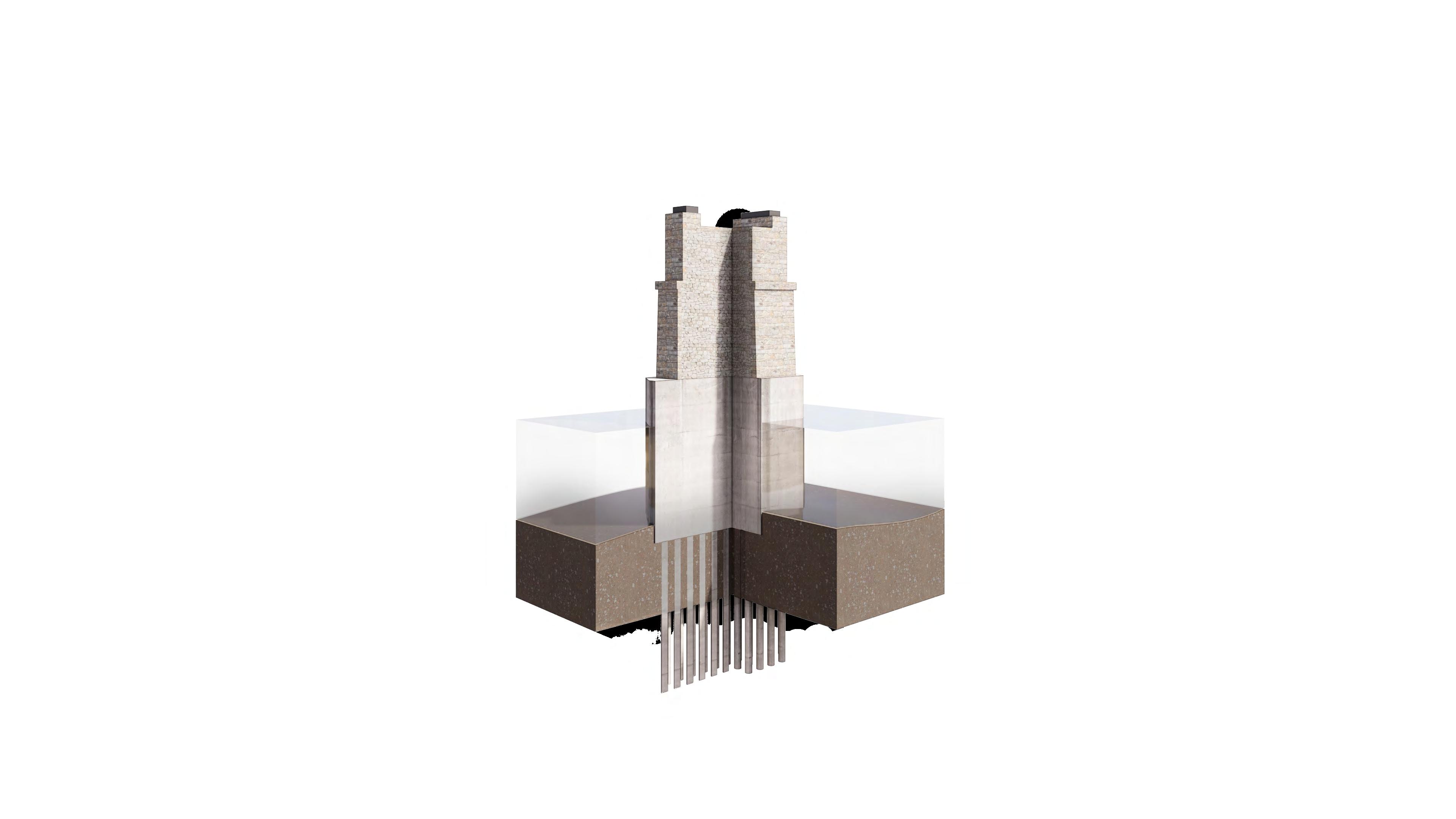
ANALYSIS OF EXISTING PIERS
The original 1880’s limestone priers have historically held four different bridges since their initial construction, and so have become an essential part of the city’s historic material fabric. By analysing historic photographs and drawings it has been possible to guess their dimensions and composition.
20m 20m 15m 3.7m Danube Basin 20m 20m 15m 3.7m Danube Basin 11m 460m 32m 75.9m 75.6m 137m 107m 32.6m ~15m
Perimeter walls of pier from limestone masonry
Masonry infill most likely composed of clay bricks, gravel and cement
Reinforced concrete foundation. Typical cross-section provides minimal resistance to water flow
Reinforced concrete foundation piles
Arched Bridge 340m longest span, 2 piers
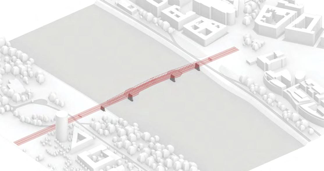
BRIDGE MASSING STUDY
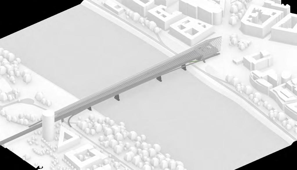
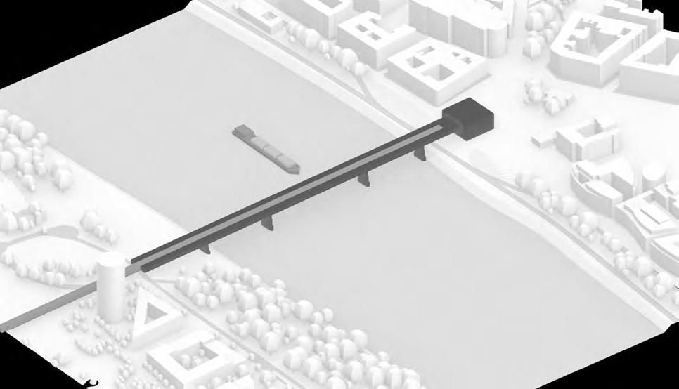
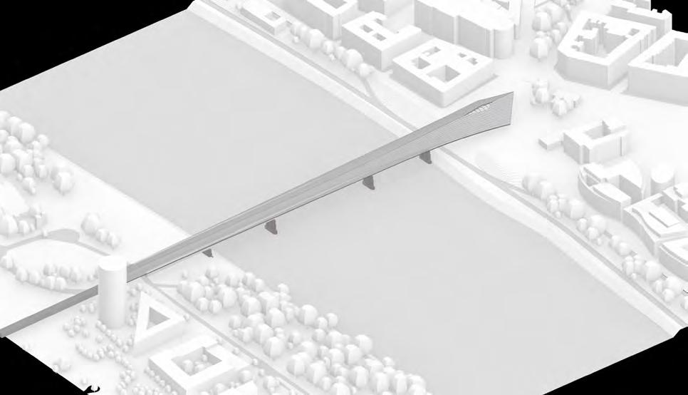
BRIDGE MASSING STUDY
Initial study focusing on overall bridge volume and scale in relation to structural strategy dictated by large spans across the wide river Danube. Study raises questions of the relationship between the Terminal Building, its bridging counterpart and the integration into the surrounding urban fabric.
Rigid Frame Bridge
Girder-Box section prefab frame, 4 piers 134m longest span
Initial study focusing on overall bridge volume and scale in relation to structural strategy dictated by large spans across the wide river Danube. Study raises questions of the relationship between the Terminal Building, its bridging counterpart and the integration into the surrounding urban fabric.
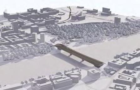
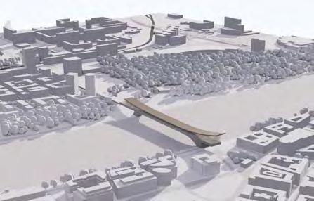
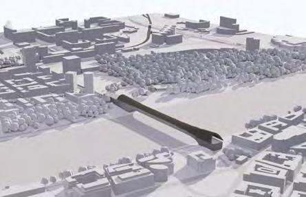
380 m 290 m 134 m 126 m 394 m 134 m 290 m 340 m OPT 1 Beam Bridge Girder-Box section prefab frame 340m longest span, 2 piers OPT 3 Arched Bridge 340m longest span, 2 piers OPT 2 Arched Bridge 380m longest span, 2 piers
4
290 m 340 m DESIGN DEVELOPMENT | BRATISLAVA TERMINAL DESIGN PORTFOLIO | BRATISLAVA TERMINAL INHABITING
OPT
Rigid Frame Bridge Girder-Box section prefab frame, 4 piers 134m longest span
380 m 290 m 134 m 126 m 394 m 134 m 290 m 340 m OPT 1 Beam Bridge
3
2
Girder-Box section prefab frame 340m longest span, 2 piers OPT
OPT
Arched Bridge 380m longest span, 2 piers
OPT 4
290 m 340 m DESIGN DEVELOPMENT | BRATISLAVA TERMINAL DESIGN
| BRATISLAVA
INHABITING
PORTFOLIO
TERMINAL
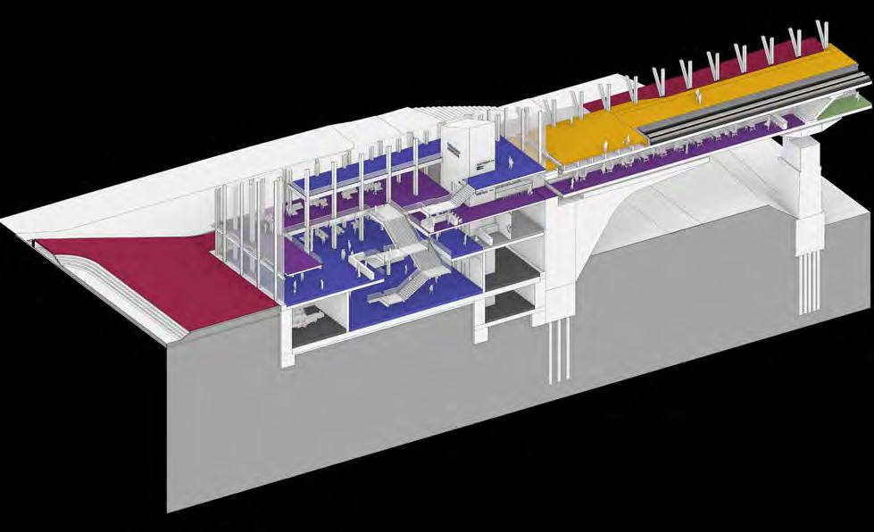
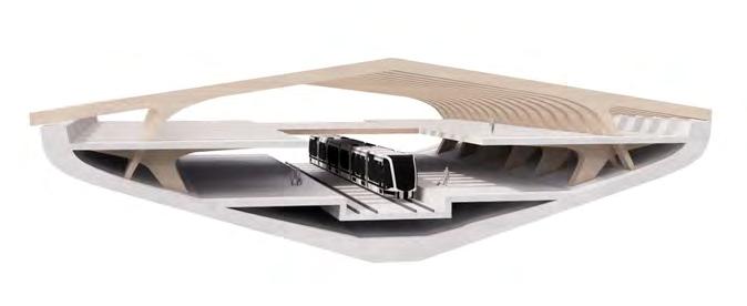
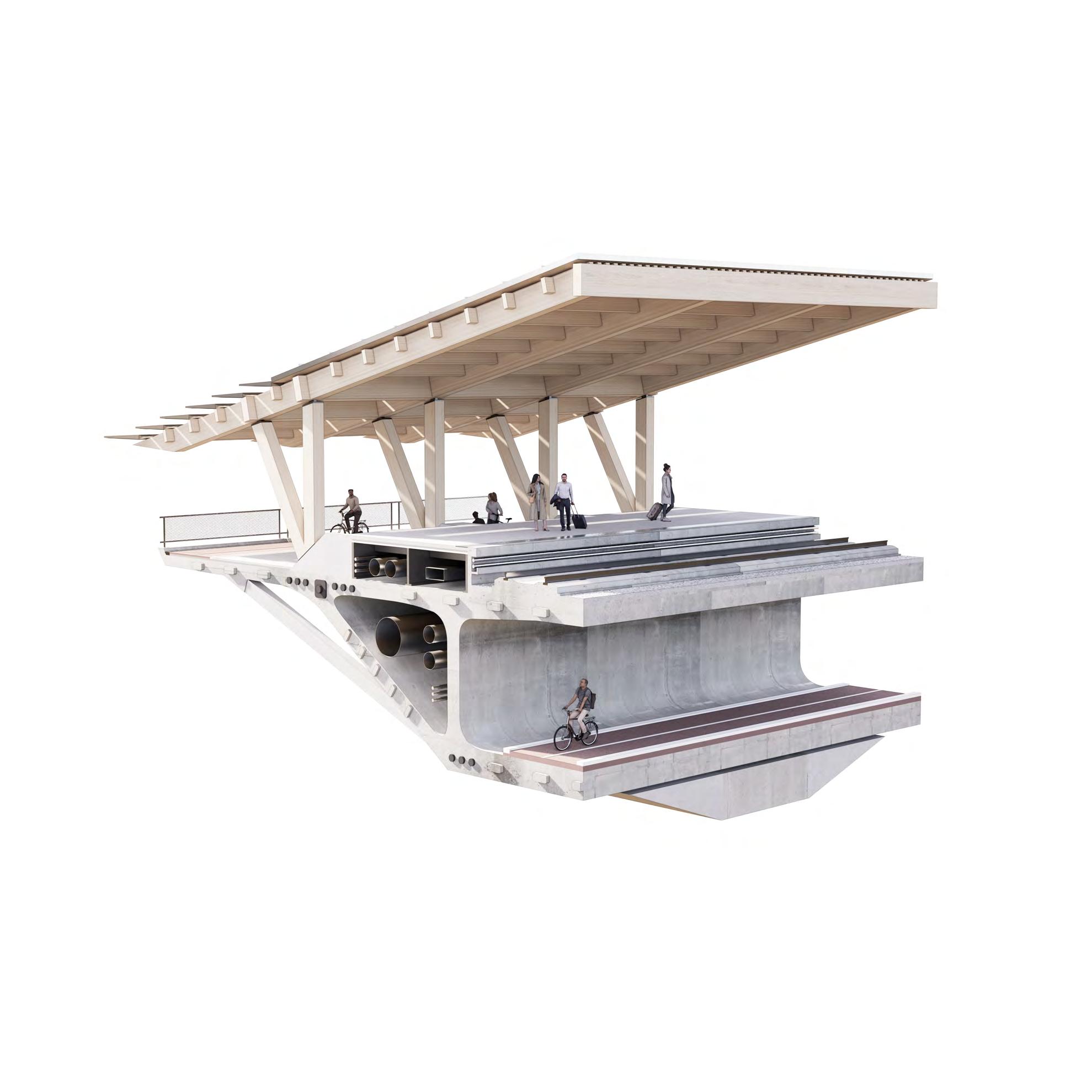
INHABITING STRUCTURE: BRIDGE CROSS SECTION
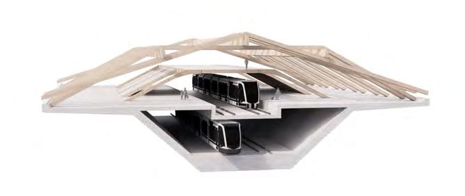
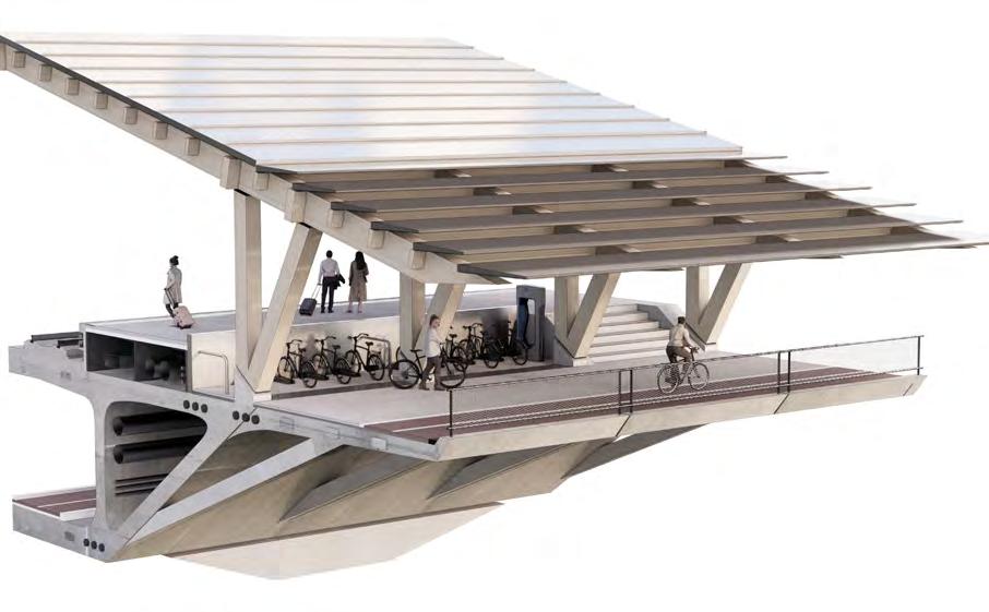
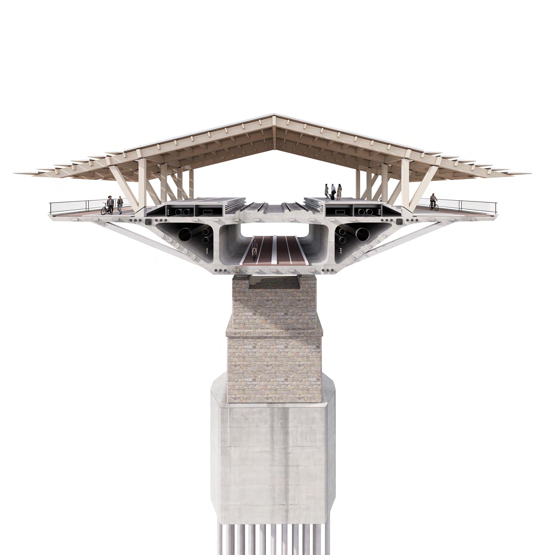
10.8 m 5.2 m 54 m 8.7 m 7.2 m 58 m Station embedded in girder-box Timber structure supporting public promenade Timber roof structure acting as envelope Station embedded in girder-box Timber structure supporting public promenade Timber roof structure acting as envelope Station embedded in girder-box Deeper box section allows for two levels of platforms Timber roof structure acting as envelope Public programme above station platforms Station embedded in girder-box Public promenade on section perimeter Timber roof structure acting as envelope Public programme above station platforms 8.0 m 9.0 m 50 m 6.8 m 9.0 m 52 m
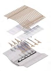
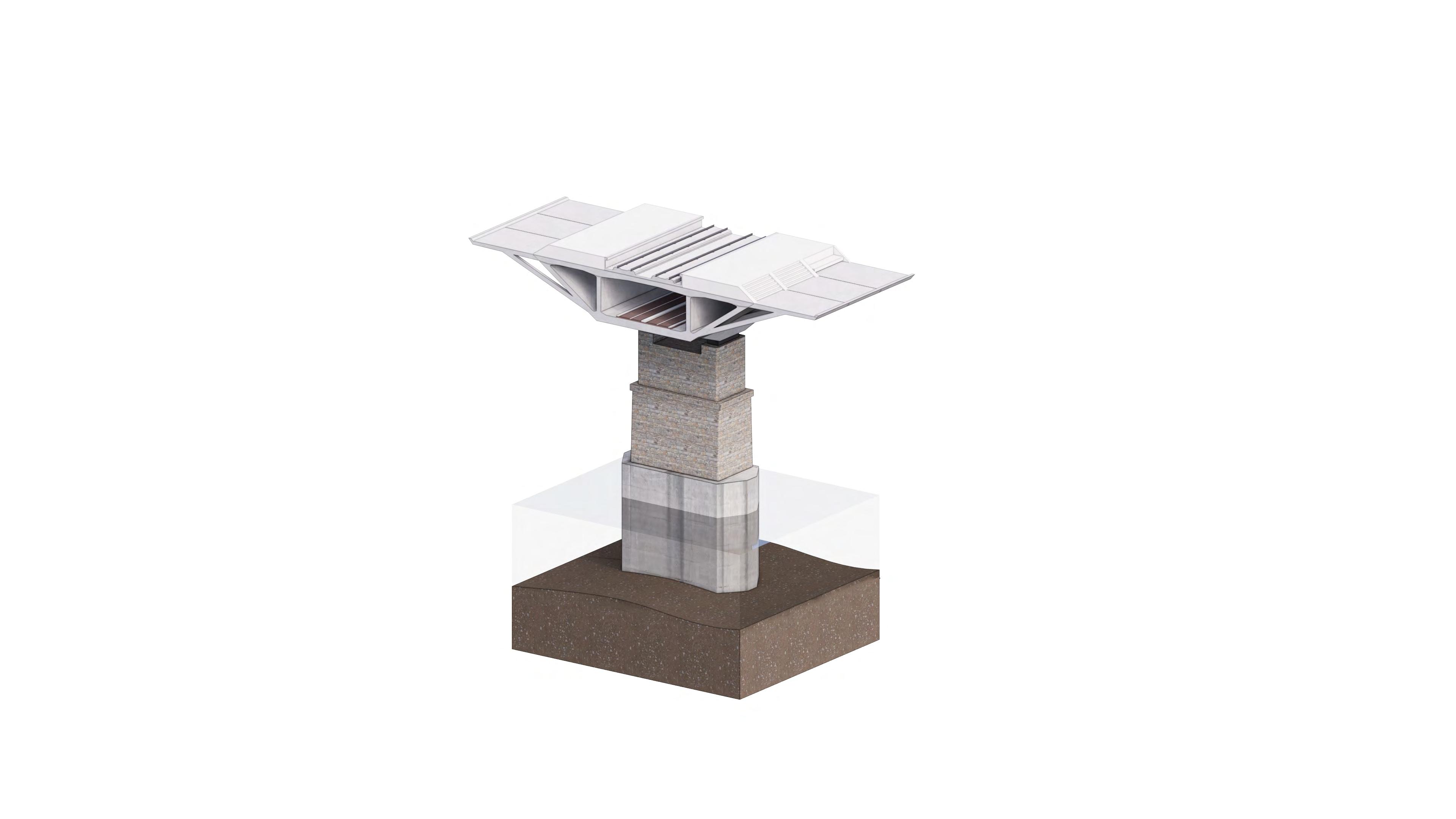
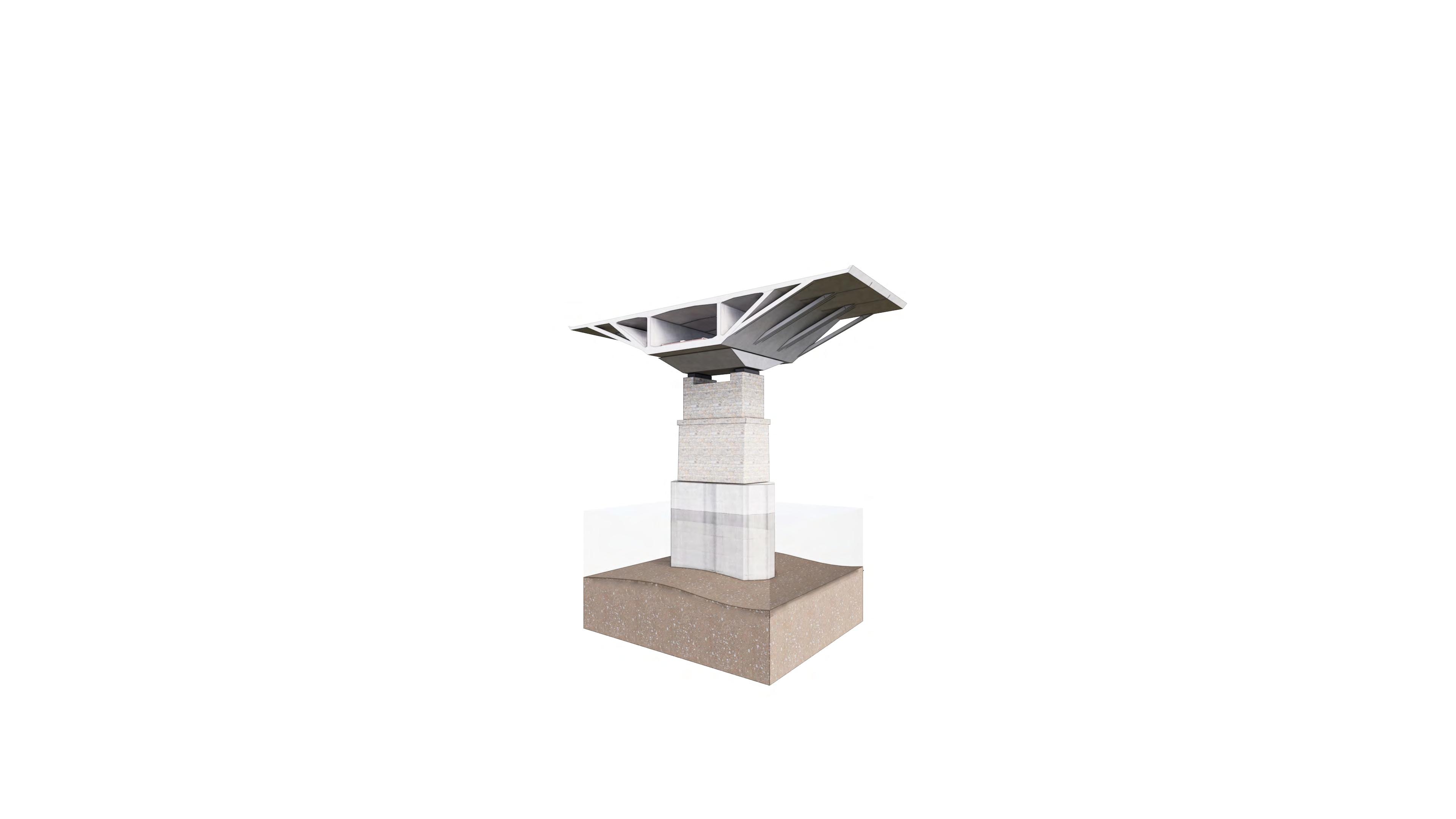
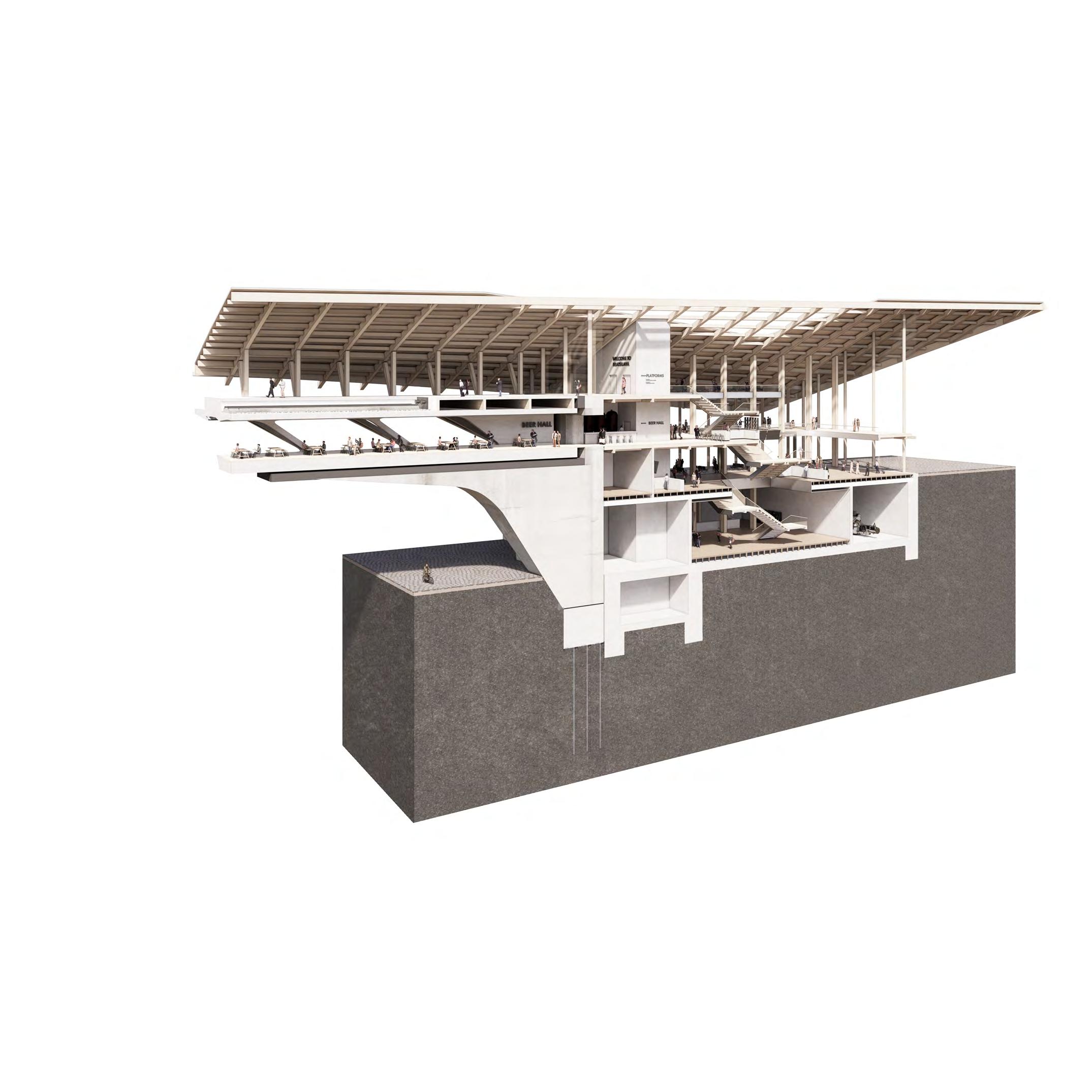
MATERIAL LAYERING: CITY STRATA
MATERIAL LAYERING: CITY STRATA
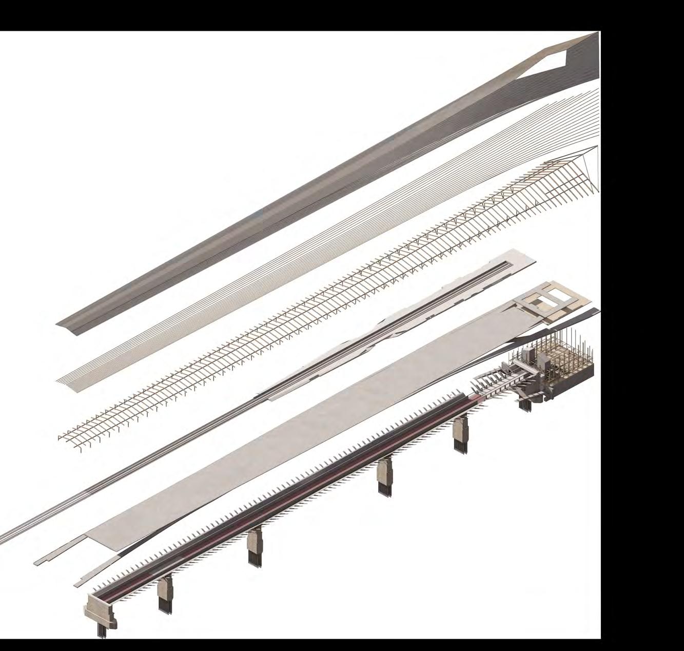
The overarching material strategy for the proposal reflects on the material strata of historic surrounding context. The bottom strata are the existing limestone piers from the 19th century. The middle and main portion of the bridge is from pre-fabricated concrete modules reflecting the south bank Petrzalka -
The overarching material strategy for the proposal reflects on the material strata of historic surrounding context. The bottom strata are the existing limestone piers from the 19th century. The middle and main portion of the bridge is from pre-fabricated concrete modules reflecting the south bank Petrzalka -
a Socialist masterplan designed and built completely from prefabricated concrete modules. The last layer is the timber frame of the bridge and terminal hall. This part looks both to the past and future and as the largest timber structures in the city aims to set precedent within the region when it comes to these technologies.
a Socialist masterplan designed and built completely from prefabricated concrete modules. The last layer is the timber frame of the bridge and terminal hall. This part looks both to the past and future and as the largest timber structures in the city aims to set precedent within the region when it comes to these technologies.
MASSING
DESIGN
STRATEGY: MATERIAL LAYERING AND CITY STRATA
PORTFOLIO | BRATISLAVA TERMINAL
MASSING
MATERIAL LAYERING AND CITY STRATA
STRATEGY:
DESIGN PORTFOLIO | BRATISLAVA TERMINAL
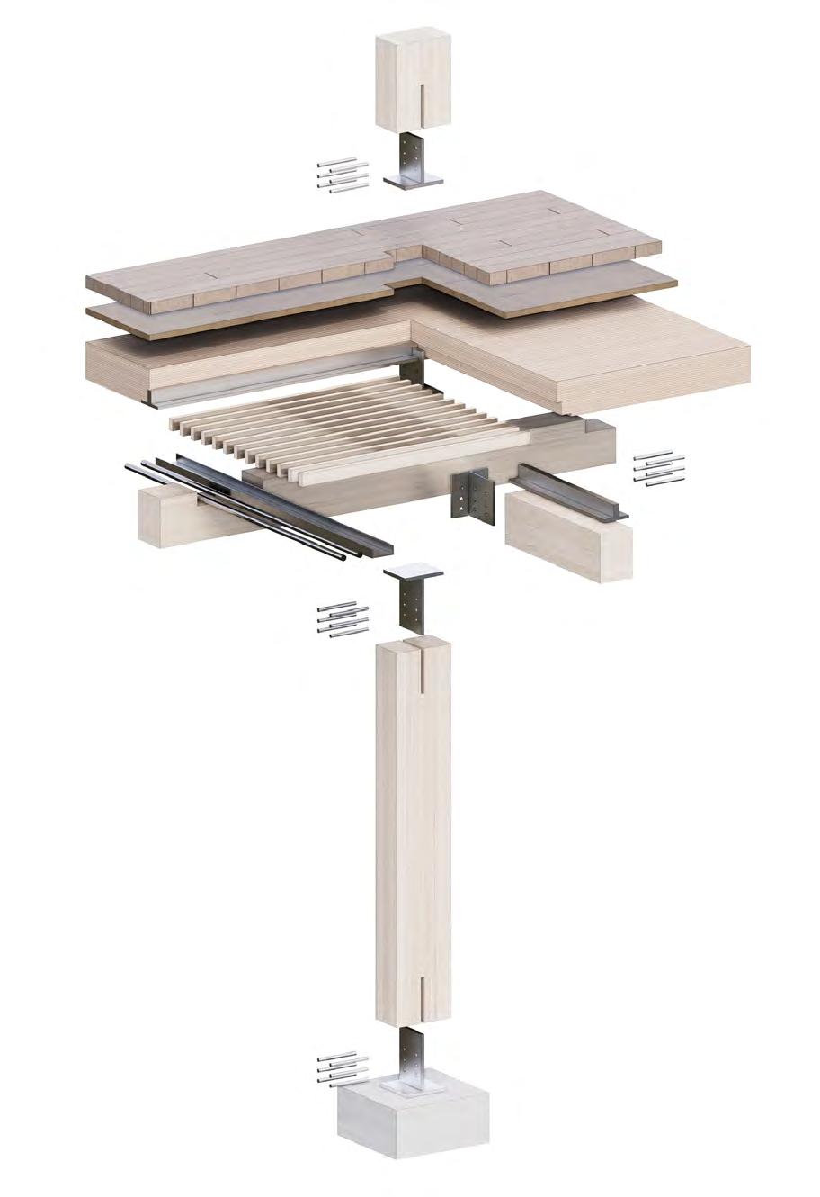
Light roof cladding; solar shingles
Pre-fab, Pre-stressed girder module
Original 1880’s limestone section
Primary glulam roof structure; sitting on girder edge
 Pre-fab, prestressed concrete box girder module
Original 1880’s bridge pier; limestone section with infill
Primary timber roof structure Glulam columns supporting bridge roof Station Platforms
Roof cladding; solar shingles Acoustic treatment
Pre-stressed RC box module of bridge body
1880’s bridge pier; section with infill
Thermally enclosed Terminal Hall
Secondary glulam roof structure
Pre-fab, prestressed concrete box girder module
Original 1880’s bridge pier; limestone section with infill
Primary timber roof structure Glulam columns supporting bridge roof Station Platforms
Roof cladding; solar shingles Acoustic treatment
Pre-stressed RC box module of bridge body
1880’s bridge pier; section with infill
Thermally enclosed Terminal Hall
Secondary glulam roof structure
Train tracks
Internal high-speed cycle-path
Train tracks
Internal high-speed cycle-path
Cavities for services
Cavities for services
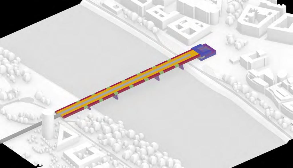
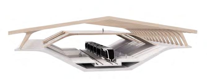
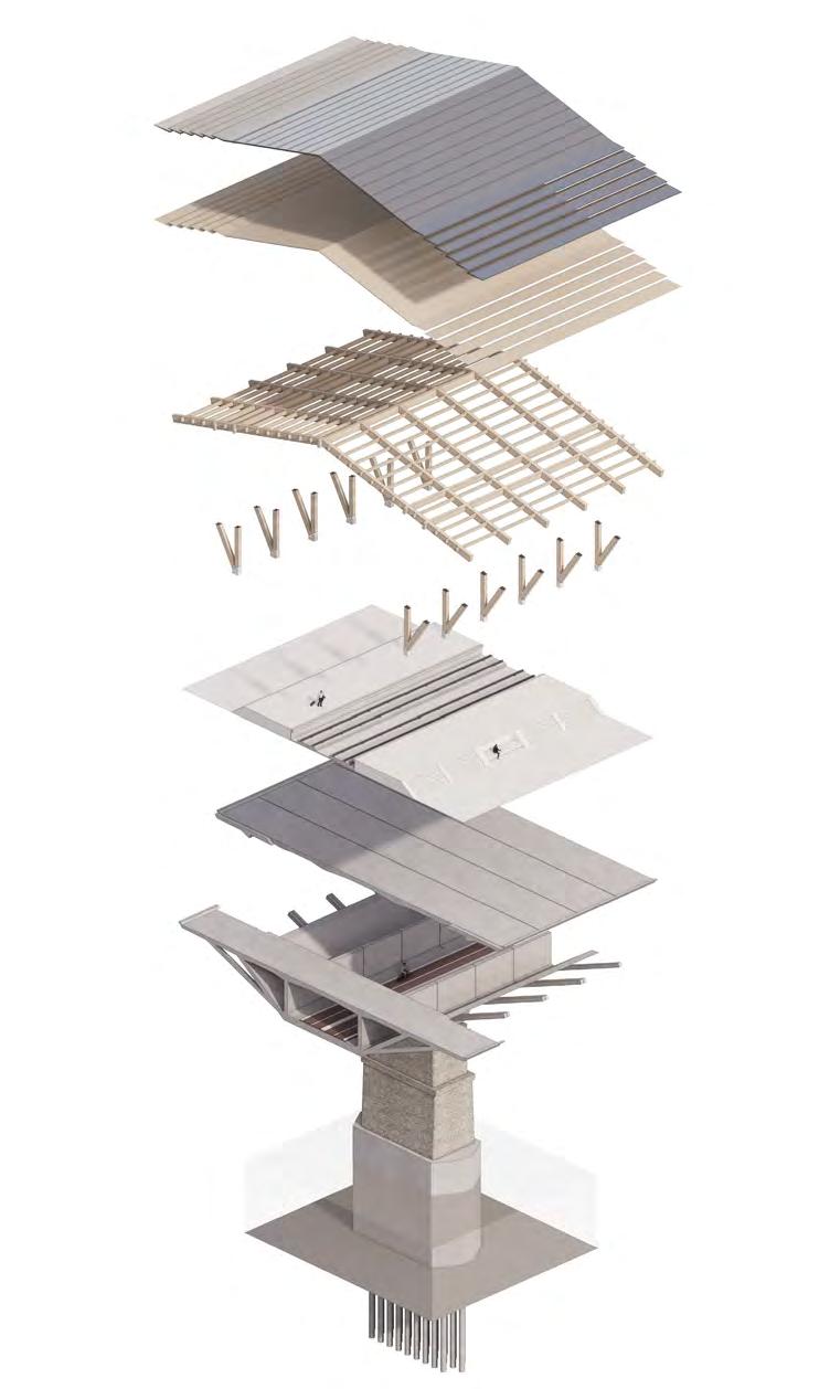
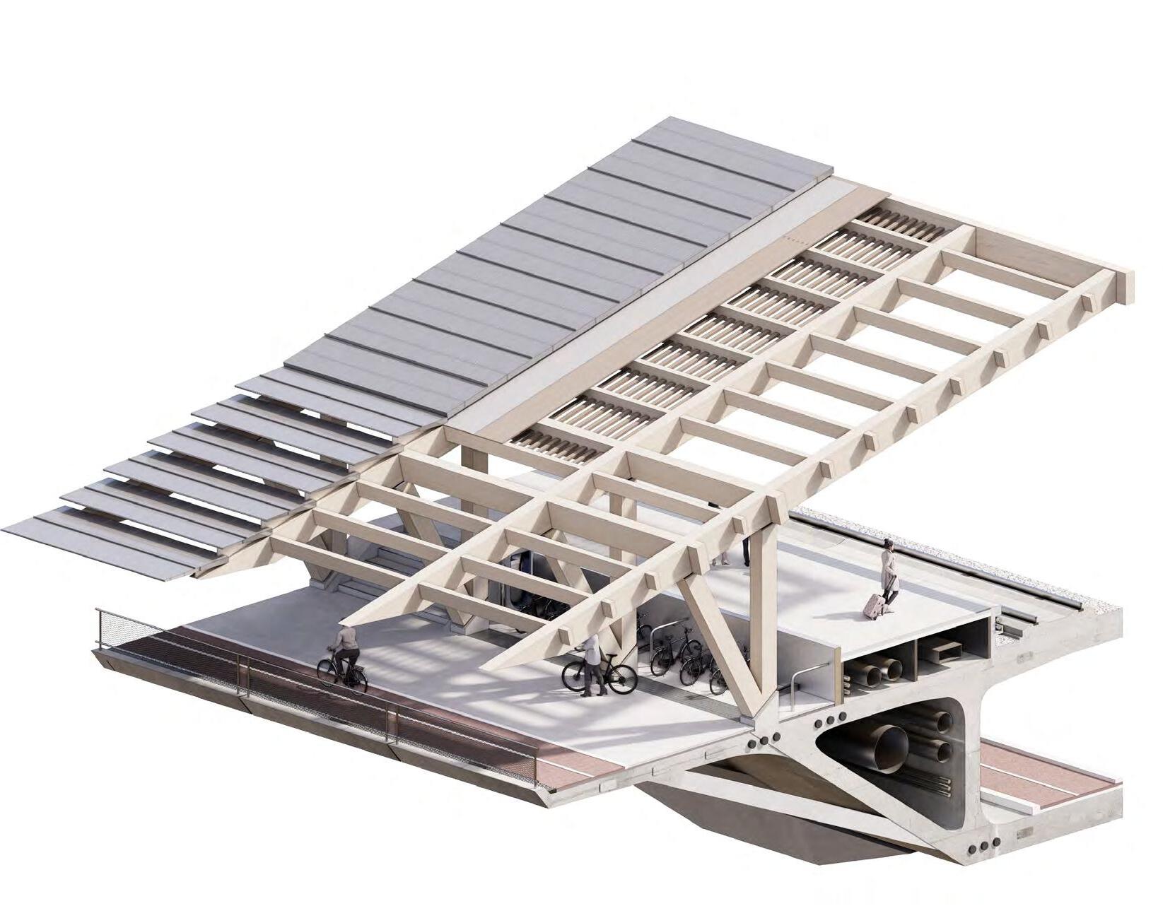
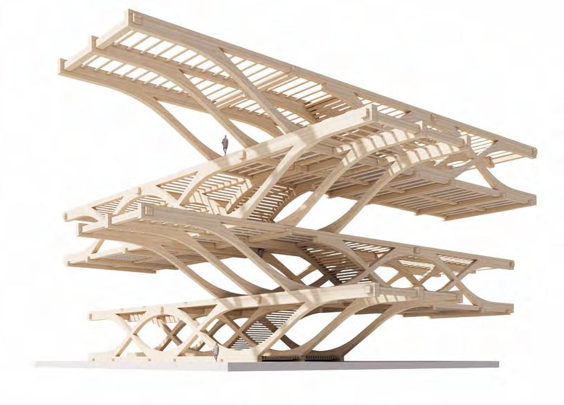
INHABITING STRUCTURE: PROGRAMMATIC INTEGRATION
INHABITING STRUCTURE: PROGRAMMATIC INTEGRATION
Public promenade with external cycle-paths
Public promenade with external cycle-paths
Station Platforms
Station Platforms
The key strategy for the bridge structure was to integrate the station programme into it as seamlessly as possible, thus creating an inhabitable city structure. The structural sizing was informed by the programmatic requirements, circulation strategies and key principles of the box-girder forming a compact cross-section.
The key strategy for the bridge structure was to integrate the station programme into it as seamlessly as possible, thus creating an inhabitable city structure. The structural sizing was informed by the programmatic requirements, circulation strategies and key principles of the box-girder forming a compact cross-section.
CROSS
Cross-section structural
BRIDGE
+ PROGRAMMATIC INTEGRATION
STRUCTURE
DESIGN PORTFOLIO | BRATISLAVA TERMINAL
15m 8.8m 15m 8.8m 15m 8.8m BRIDGE STRUCTURE + PROGRAMMATIC INTEGRATION 24.0 DESIGN
|
PORTFOLIO
BRATISLAVA TERMINAL
CROSS PIER CONDITION
CROSS SECTION DEVELOPMENT
Cross-section developing based on programmatic, circulation and structural requirements and sizing.
134m 134m 5m 14.5m 16m 15m 9m 5m 10m 4.5m 8m 7.8m 8.8m 7m 18m 7.5m 6m 6m 7.5m 11.5m 11.5m 11.5m 11.5m 6m 6m 11.5m 11.5m 7.5m 7.5m 11.5m 11.5m 23m 7.5m 7.5m 11.5m 11.5m 23m 23m 38m 7.5m 7.5m 11.5m 11.5m 38m 35m 134 m 134m 134m 5m 14.5m 16m 15m 9m 5m 10m 4.5m 8m 7.8m 8.8m 7m 18m 7.5m 6m 6m 7.5m 11.5m 11.5m 11.5m 11.5m 6m 6m 11.5m 11.5m 7.5m 7.5m 11.5m 11.5m 23m 7.5m 7.5m 11.5m 11.5m 23m 23m 38m 7.5m 7.5m 11.5m 11.5m 38m 35m 134 m 134m 134m 5m 14.5m 16m 15m 9m 5m 10m 4.5m 8m 7.8m 8.8m 7m 18m 7.5m 6m 6m 7.5m 11.5m 11.5m 11.5m 11.5m 6m 6m 11.5m 11.5m 7.5m 7.5m 11.5m 11.5m 23m 7.5m 7.5m 11.5m 11.5m 23m 23m 38m 7.5m 7.5m 11.5m 11.5m 38m 35m 134 m P2 P1 A1 F1 P3 P4 A2 137.0 18.0 24.0 80.0 45.0 50.0 90.0 95.0 P2 P1 A1 F1 P3 P4 A2 137.0 80.0 45.0 50.0 90.0 95.0 Platforms with CROSS SECTION CONDITIONS PIER CONDITION TYPICAL CONDITION END CONDITION 10.8 m 5.2 m 54 m 6.8 m 9.0 m 52 m 8.5 m 9.0 m 8.5 m 8.7 m 8.0 m 9.0 m 50 m 7.2 m 58 m 35 m 6 m 8 m 28 m 5 m
DESIGN PORTFOLIO | BRATISLAVA TERMINAL
DESIGN PORTFOLIO | BRATISLAVA TERMINAL
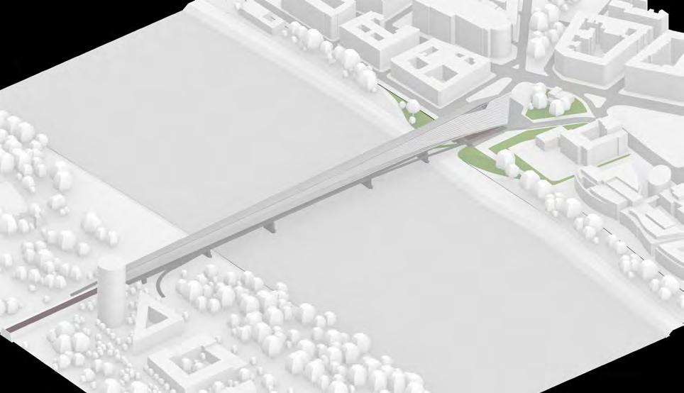
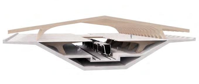
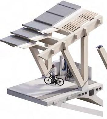
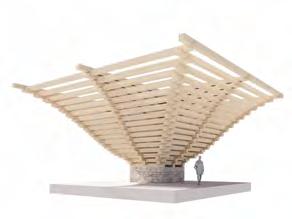
STRATEGY: SHELTERED PROMENADE
STRATEGY: SHELTERED PROMENADE
STRATEGY: SHELTERED PROMENADE
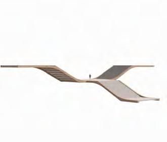
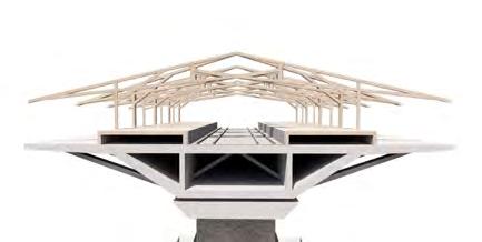
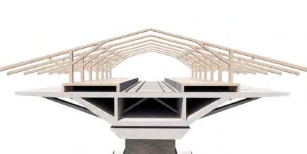
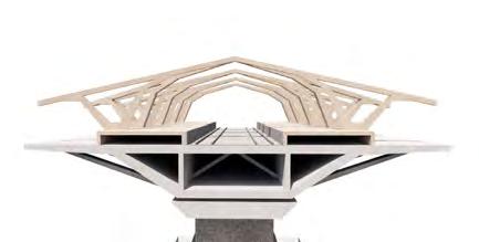
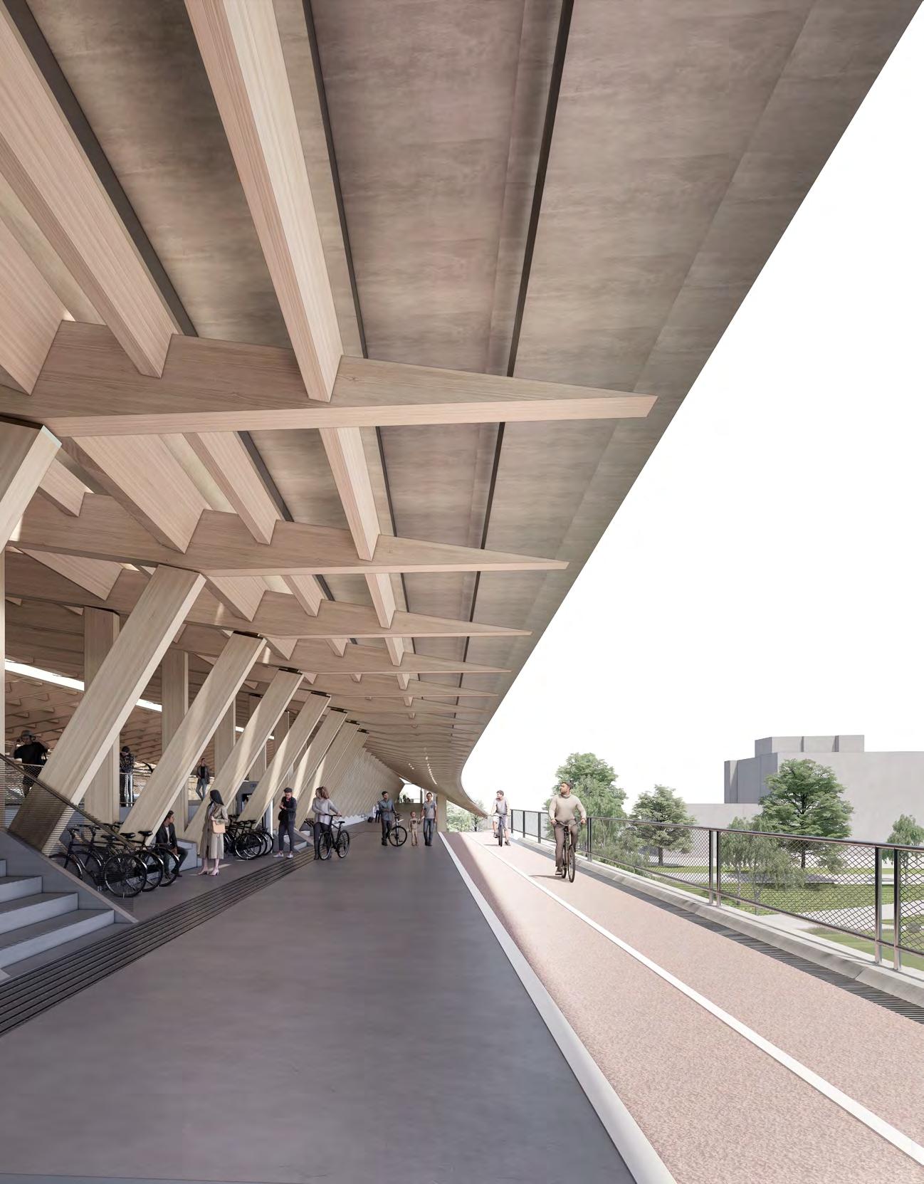
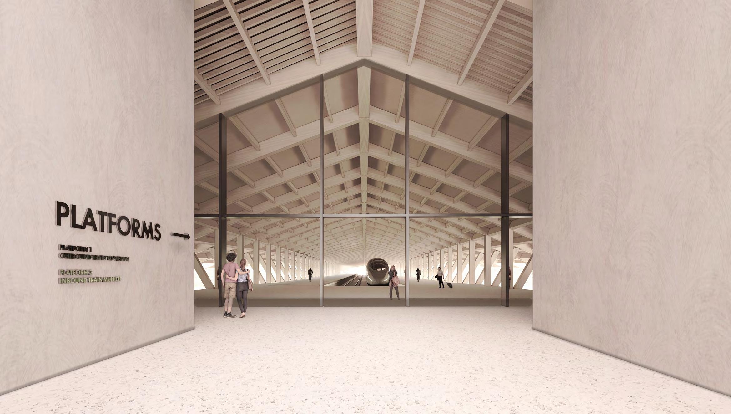
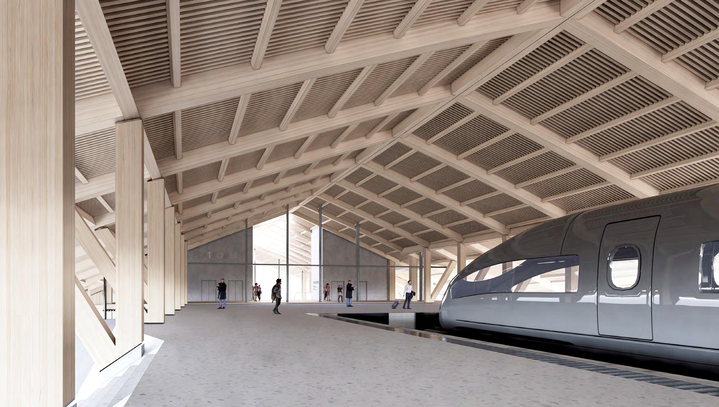
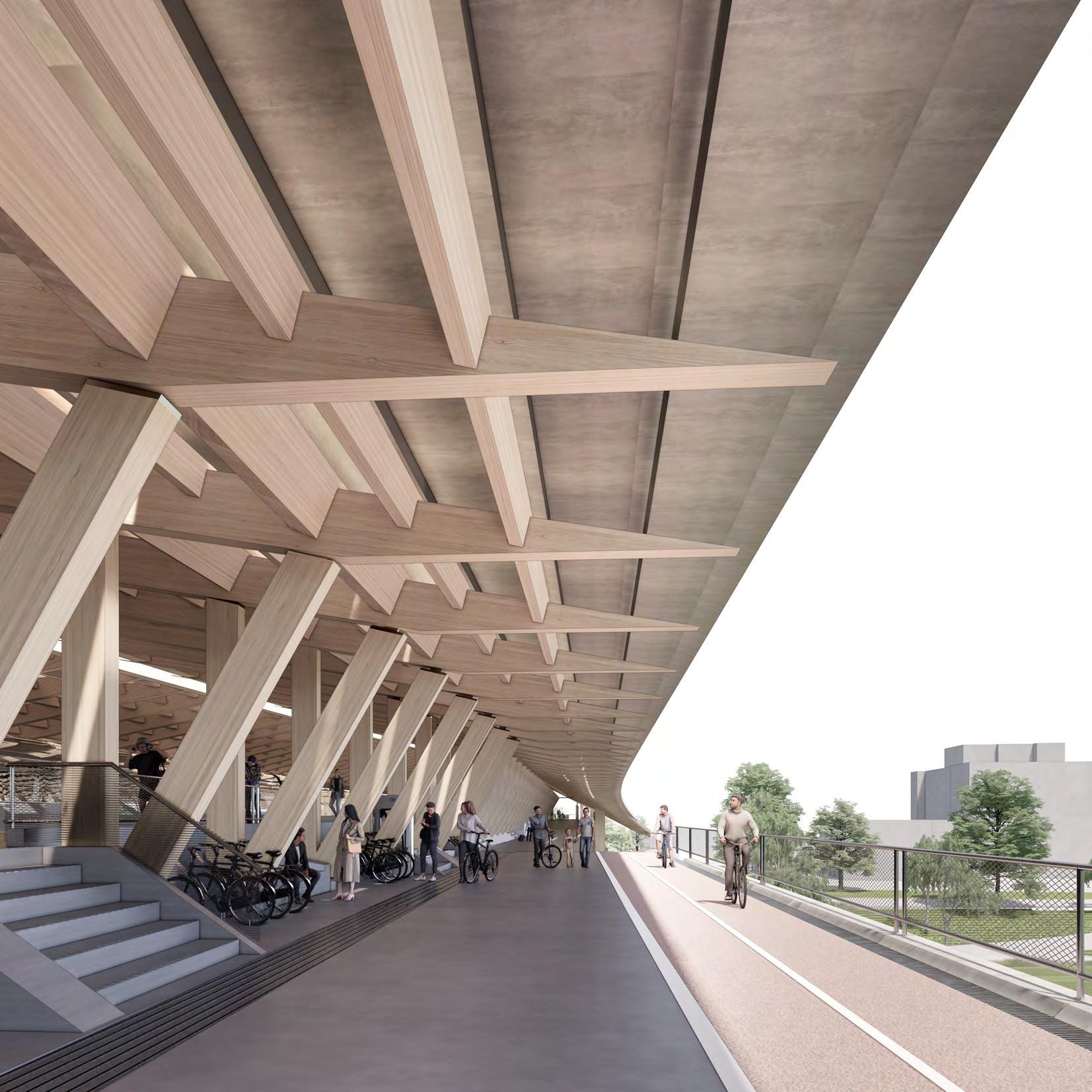
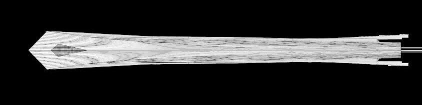
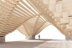
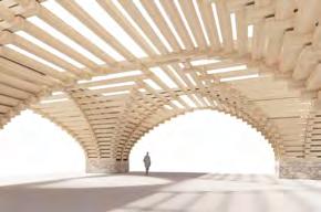
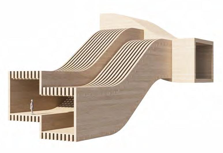
Inspired by Slovak vernacular roof frames, the structure is simple and utilitarian, allowing the materials to speak for themselves. It’s slope reflects the form of the box girder below, while horizontal openings to its perimeter bring in additional light onto the platforms.
Inspired by Slovak vernacular roof frames, the structure is simple and utilitarian, allowing the materials to speak for themselves. It’s slope reflects the form of the box girder below, while horizontal openings to its perimeter bring in additional light onto the platforms.
DESIGN PORTFOLIO | BRATISLAVA TERMINAL
Inspired by Slovak vernacular roof frames, the structure is simple and utilitarian, allowing the materials to speak for themselves. It’s slope reflects the form of the box girder below, while horizontal openings to its perimeter bring in additional light onto the platforms.
INTERMOBILITY: SHELTERED PROMENADE
INTERMOBILITY: SHELTERED PROMENADE
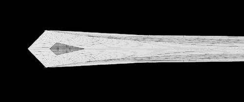
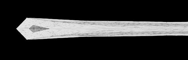
ROOF FORM STUDY: EAVES
ROOF FORM STUDY: EAVES
ROOF FORM STUDY: EAVES
ROOF FORM STUDY: EAVES
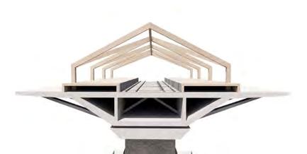
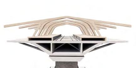
The roof form was shaped by studying the depth of the roof overhanging eaves, to create a protected circulation route on the bridge perimeter and keep rain away from platforms.
The roof form was shaped by studying the depth of the roof overhanging eaves, to create a protected circulation route on the bridge perimeter and keep rain away from platforms.
The roof form was shaped by studying the depth of the roof overhanging eaves, to create a protected circulation route on the bridge perimeter and keep rain away from platforms.
The roof form was shaped by studying the depth of the roof overhanging eaves, to create a protected circulation route on the bridge perimeter and keep rain away from platforms.
Circulation Types:
 1.
2.
3.
1. External Cycle Lane
2. Pedestrian Promenade
3. Platform
4. Railway tracks
5. Internal Cycle-lane
1.
2.
3.
1. External Cycle Lane
2. Pedestrian Promenade
3. Platform
4. Railway tracks
5. Internal Cycle-lane
 5.
3.
4.
RAILWAY PLATFORM
CYCLE PATH
PEDESTRIAN PROMENADE
5.
3.
4.
RAILWAY PLATFORM
CYCLE PATH
PEDESTRIAN PROMENADE
DESIGN PORTFOLIO | BRATISLAVA TERMINAL
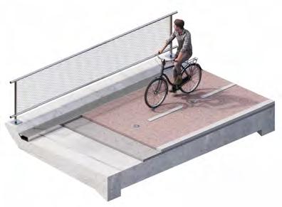
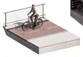
CYCLE STATION: SAFE TRANSPORT INTERCHANGE

The strategy of integrated transport is to have bike-sharing stands directly next to the platforms throughout the bridge so passengers can change their mode of transport without leaving the station [bridge].
BRATISLAVA TERMINAL
PORTFOLIO
Currently two of the most frequented public transport interchanges in the city center
LINKING DISJOINT CITY INFRASTRUCTURE
LINKING DISJOINT CITY INFRASTRUCTURE
CYCLE PATHS
CYCLE PATHS
PUBLIC TRANSPORT LINKS
TRAM LINE
PUBLIC TRANSPORT LINKS
TRAM LINE
AREAS UNDER DEVELOPMENT
AREAS UNDER DEVELOPMENT
HIGHLY FREQUENTED PUBLIC TRANSPORT HUBS
HIGHLY FREQUENTED PUBLIC TRANSPORT HUBS
Currently two of the most frequented public transport interchanges in the city center DESIGN PORTFOLIO | BRATISLAVA TERMINAL
IMPACT ON CITY INFRASTRUCTURE
DESIGN
|
IMPACT ON CITY INFRASTRUCTURE
Direct connection of station to city public transport
Interconnecting cycle lanes on both banks
Direct connection to international EUROVELO cycle route
IV. BRATISLAVA TERMINAL FINAL
PROPOSAL
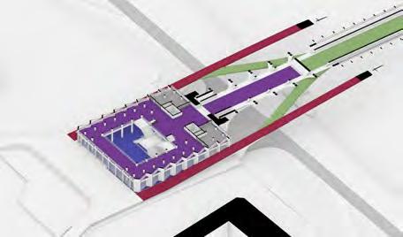
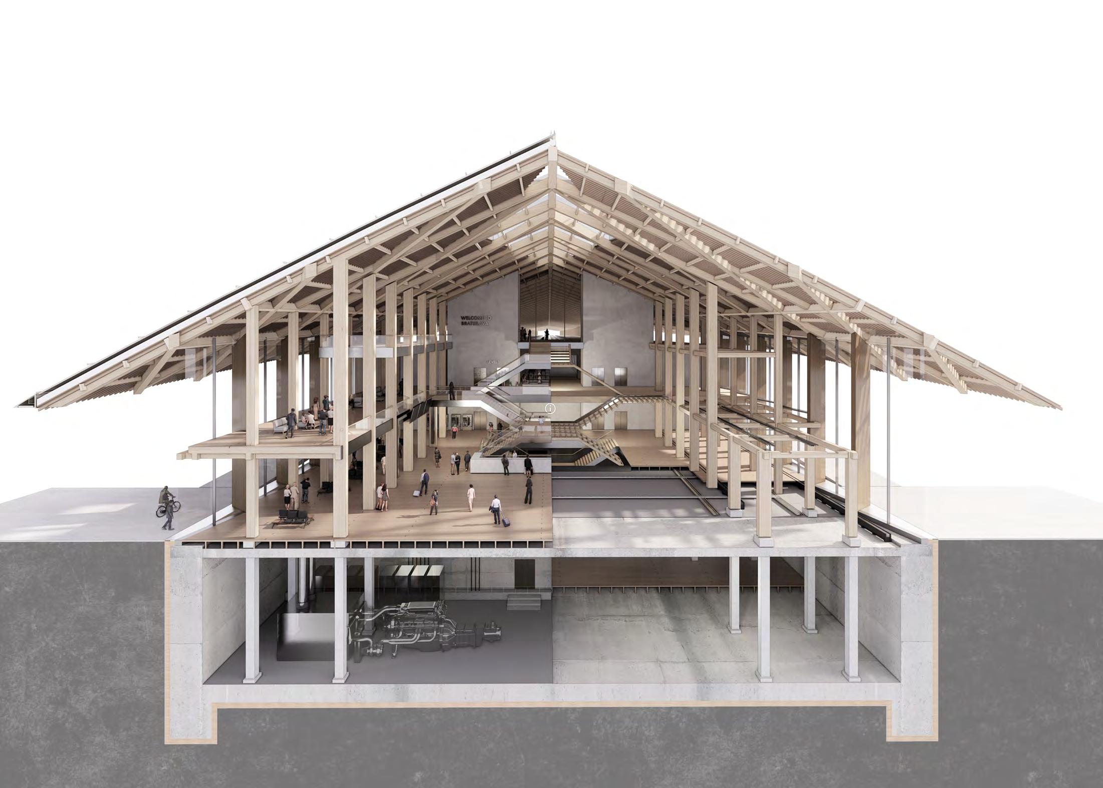
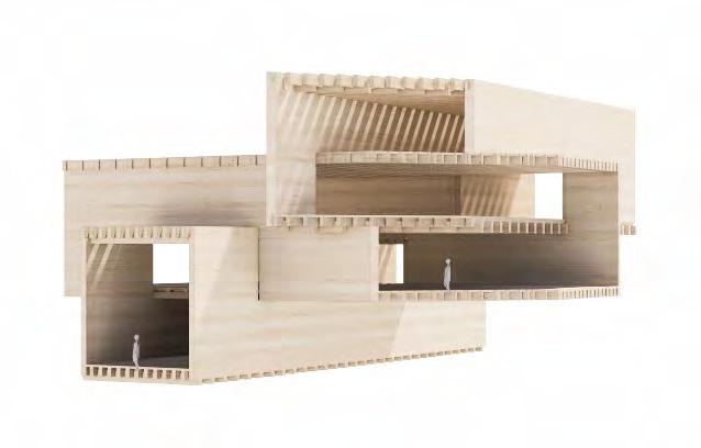
SPATIAL ARRANGEMENT: STATION DIRECTIONALITY
TERMINAL TO BRIDGE CONNECTION
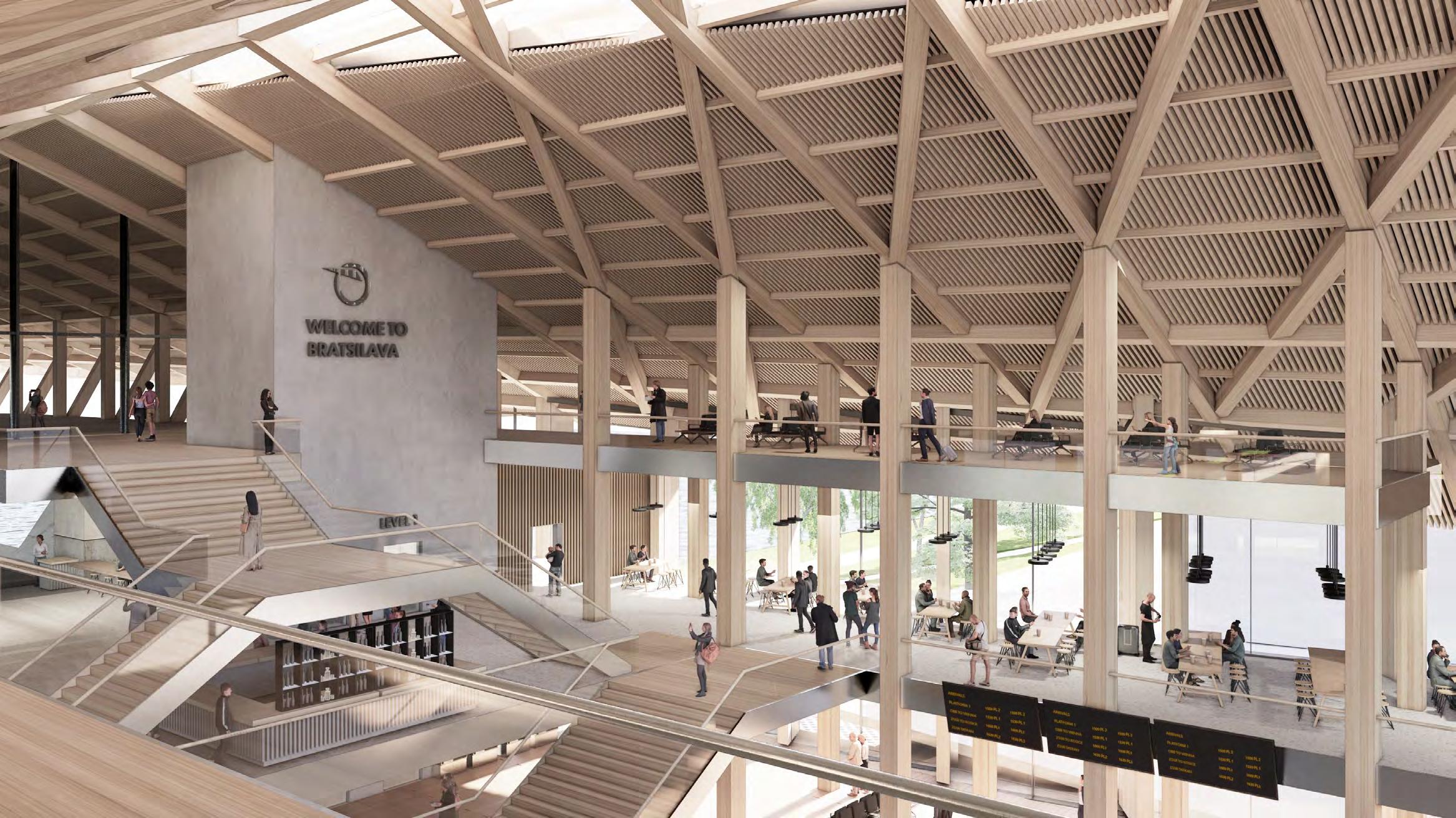
Terminal short section: The station is designed to offer a clear, direct route for passengers while having additional programme on the perimeter for daily visitors. The open, flexible areas, exposed structure and large roof overhang
The station is divided by a buffer zone marking the division between the bridge structure and terminal building. This is the area of bridge retention allowing for structural expansion while marking the thermal line of the terminal building. This zone also houses the bridge part of the Beer Hall.
DESIGN PORTFOLIO | BRATISLAVA TERMINAL TERMINAL TO
CONNECTION: BUFFER ZONE
BRIDGE
DESIGN PORTFOLIO | BRATISLAVA TERMINAL
BRIDGE PLATFORMS
TERMINAL
SHORT SECTION: SPATIAL ARRANGEMENT
TERMINAL
BUILDING
SPATIAL ARRANGEMENT: STATION DIRECTIONALITY
SPATIAL ARRANGEMENT: STATION DIRECTIONALITY
Terminal short section: The station is designed to offer a clear, direct route for passengers while having additional programme on the perimeter for daily visitors. The open, flexible areas, exposed structure and large roof overhang
Terminal short section: The station is designed to offer a clear, direct route for passengers while having additional programme on the perimeter for daily visitors. The open, flexible areas, exposed structure and large roof overhang
DESIGN PORTFOLIO | BRATISLAVA TERMINAL
DESIGN PORTFOLIO | BRATISLAVA TERMINAL
TERMINAL SHORT SECTION: SPATIAL ARRANGEMENT
TERMINAL SHORT SECTION: SPATIAL ARRANGEMENT
PORTFOLIO | BRATISLAVA TERMINAL
DESIGN
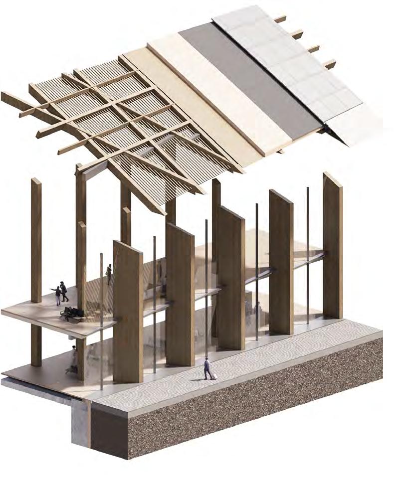
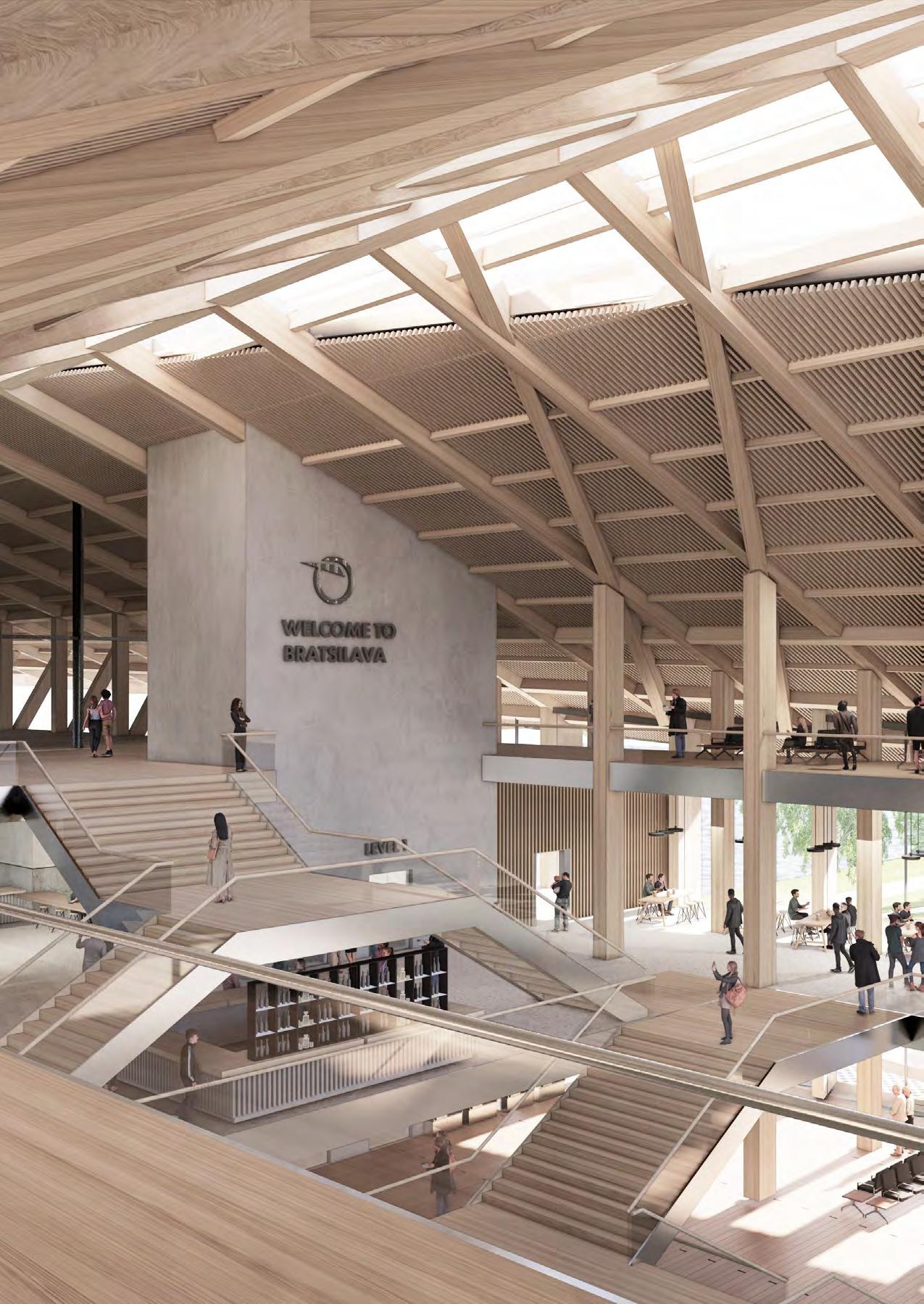
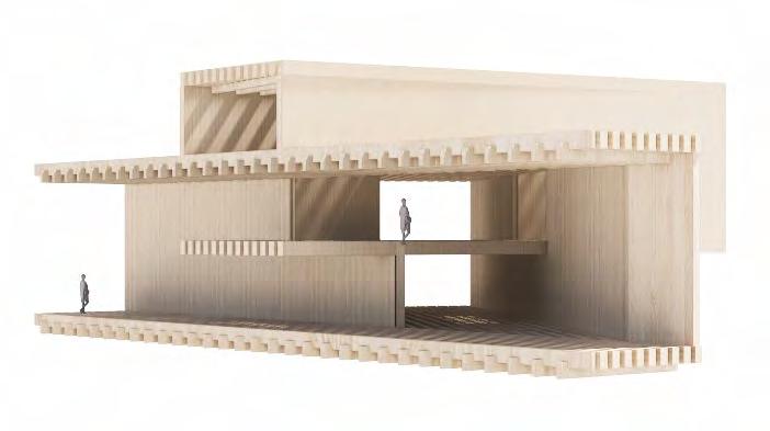
TERMINAL ENCLOSURE
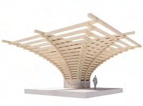
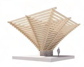
Both the roof and facade are primarily constructed from timber frame making the station an importnatbenchmark for timber construction at such scale in Slovakia, particularly due to its restrictive legislation concerning structural timber in civic buildings.
 Structural facade fins support diagonal primary timber roof members
Ground floor entrance zone around perimeter of terminal
Thermally protected terminal hall
Structural facade fins support diagonal primary timber roof members
Ground floor entrance zone around perimeter of terminal
Thermally protected terminal hall
DESIGN PORTFOLIO | BRATISLAVA TERMINAL
TERMINAL STRUCTURE
The structural strategy for the terminal hall is a glulam frame supporting the roof structure of the entire bridge. This way, timber becomes a part of the visitors journey from the terminal hall onto the bridge platforms and beyond.
DESIGN PORTFOLIO | BRATISLAVA TERMINAL
DESIGN PORTFOLIO | BRATISLAVA TERMINAL
DESIGN PORTFOLIO | BRATISLAVA TERMINAL
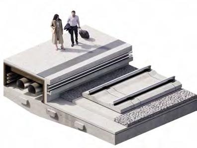
PROGRAMME LAYERING: STATION JOURNEY
PROGRAMME LAYERING: STATION JOURNEY
Journey across levels from external plaza, through the terminal [beer] hall up towards the platforms.
PROGRAMME LAYERING: STATION JOURNEY
TERMINAL LONG SECTION: PROGRAMME LAYERING
1. External plaza - buffer zone
2. Main entrance zone 3. Terminal concourse
8.
9.
10.
11.
12.
4. Ticket purchase + information 5. [Terminal] Beer Hall 6. [Bridge] Beer Hall
7.
Waiting areas
Platforms
Riverside entrance hall
B.O.H. areas
MEP areas
Riverside promenade
1.
2.
3.
5.
7.
11.
TERMINAL LONG SECTION: PROGRAMME LAYERING
BEER LOVERS
Journey across levels from external plaza, through the terminal [beer] hall up towards the platforms.
1. External plaza - buffer zone
2. Main entrance zone
3. Terminal concourse 4. Ticket purchase + information
8.
9.
10.
11.
12.
5. [Terminal] Beer Hall 6. [Bridge] Beer Hall
7.
Waiting areas
Platforms
Riverside entrance hall
B.O.H. areas
MEP areas
Riverside promenade
1.
2.
3.
5.
7.
11.
TERMINAL LONG SECTION: PROGRAMME LAYERING
BEER LOVERS
Journey across levels from external plaza, through the terminal [beer] hall up towards the platforms.
1. External plaza - buffer zone 2. Main entrance zone 3. Terminal concourse 4. Ticket purchase + information 5. [Terminal] Beer Hall 6. [Bridge] Beer Hall
7.
Waiting areas
8.
Platforms
9.
Riverside entrance hall
10.
B.O.H. areas
11.
MEP areas
12.
Riverside promenade
1.
2.
3.
5.
7.
9.
11.
BEER LOVERS TOURISTS
4.
10. 12.
8. 9.
INTER-RAILERS
6. TOURISTS +
[VIENNA] COMMUTERS
CYCLISTS + PEDESTRIANS 4.
10. 12.
8. 9.
6. TOURISTS + INTER-RAILERS
[VIENNA] COMMUTERS
CYCLISTS + PEDESTRIANS
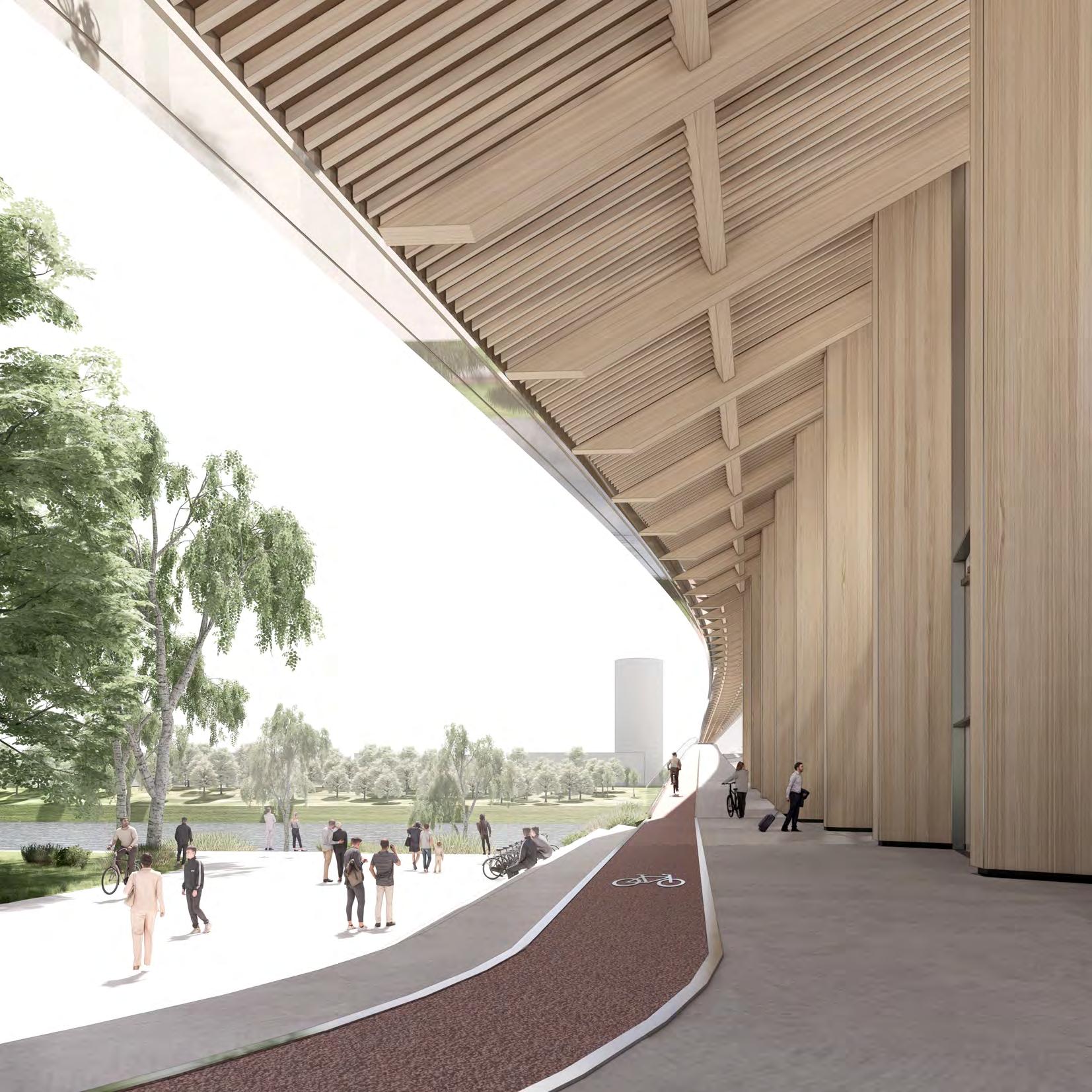
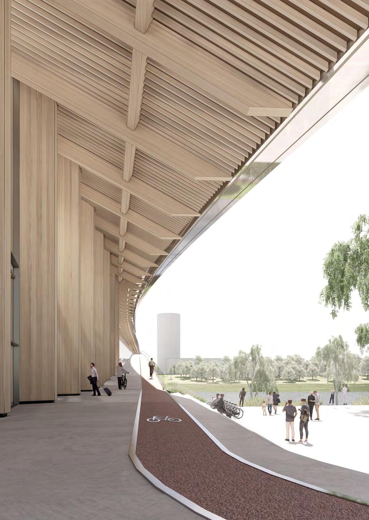
APPROACH: ROOF OVERHANG
Roof overhand creating protected perimeter circulation and public space around the terminal hall.
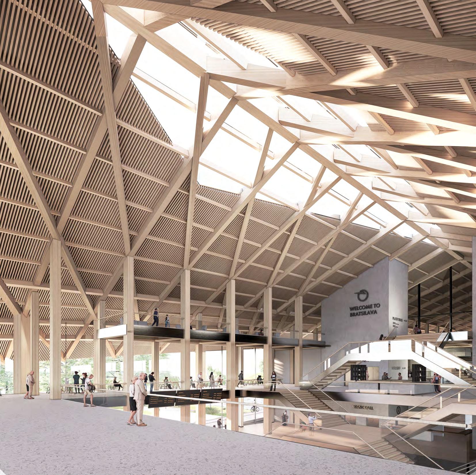
TERMINAL HALL
Roof structure creating spatial unity across the entire station terminal and bridge, playing with traditional Slovak architectural gestures.
PLATFORM ARRIVAL
The Barn: a domestic infrastructure
BRIDGE PLATFORMS
The Barn: a domestic infrastructure
[TERMINAL] BEER HALL
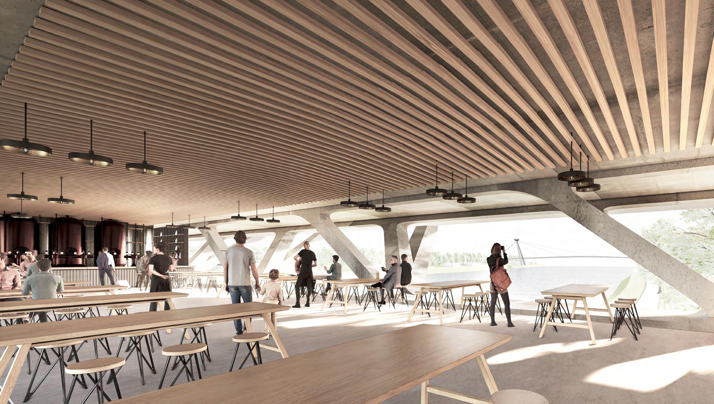 [BRIDGE] BEER HALL
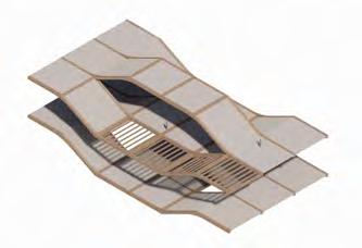
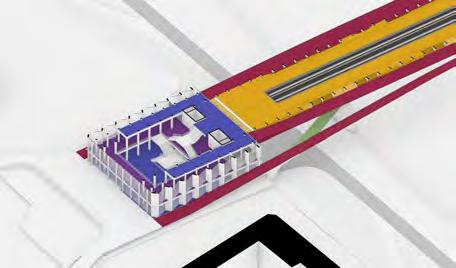
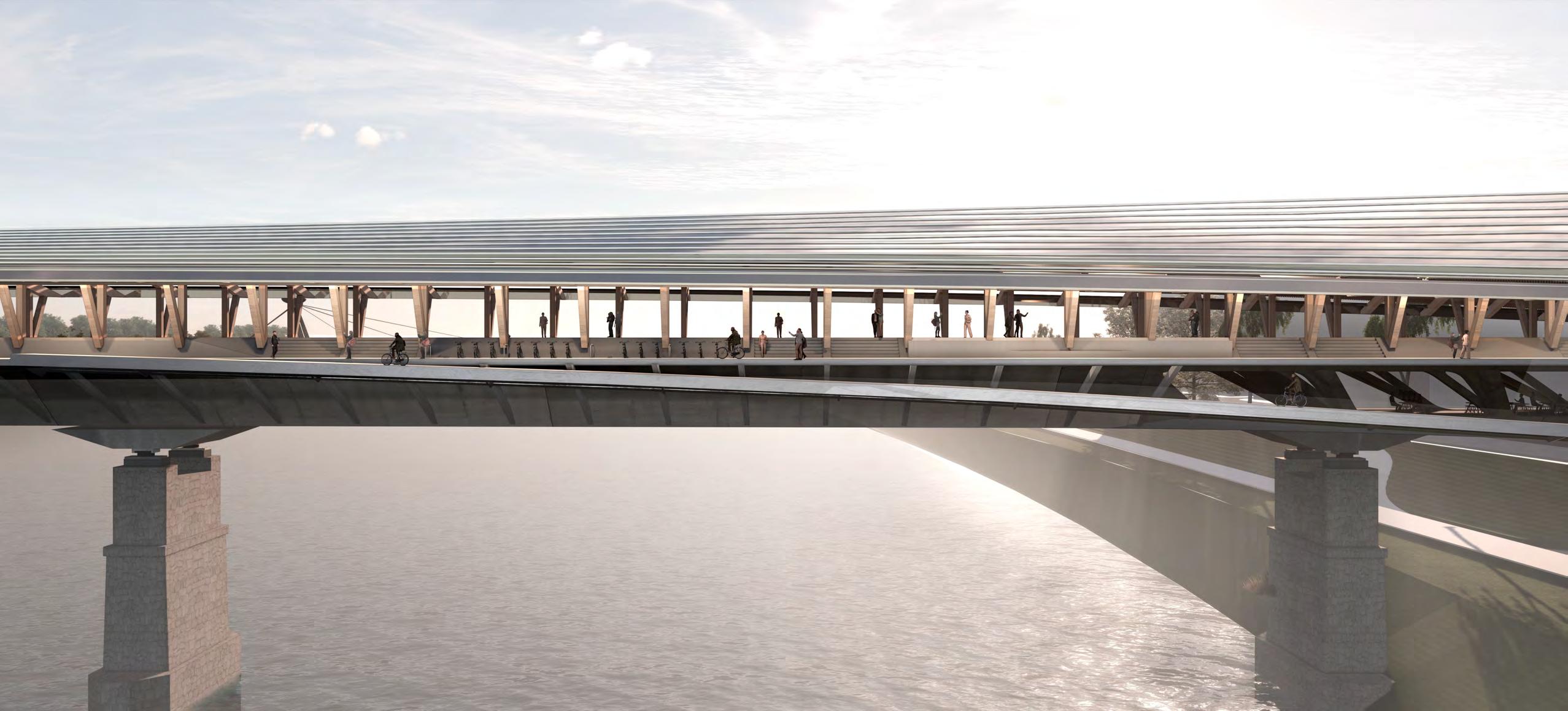
BRIDGE CROSS-SECTION: INTERMOBILITY
INTERMOBILITY: BRIDGE FRAGMENT
INTERMOBILITY: BRIDGE FRAGMENT
Cross-section of bridge exploring the different circulation routes and their separation.
Cross-section of bridge exploring the different circulation routes and their separation.
1. External cycle-lane
1. External cycle-lane
2. Pedestrian promenade
2. Pedestrian promenade
3. Railway platforms
3. Railway platforms
4. Train tracks
4. Train tracks
BRIDGE CROSS-SECTION: INTERMOBILITY
5. High-speed internal cycle-lane DESIGN PORTFOLIO | BRATISLAVA TERMINAL
5. High-speed internal cycle-lane
DESIGN PORTFOLIO | BRATISLAVA TERMINAL
 1.
5.
2.
3.
4.
1.
5.
2.
3.
4.
1.
5.
2.
3.
4.
1.
5.
2.
3.
4.
5. 4.
[CYCLE] STATION INTERCHANGE
Integration of public transport so passengers can change their mode of transport without leaving the station [bridge].
INTERMOBILITY
Elevating and layering of public infrastructure.
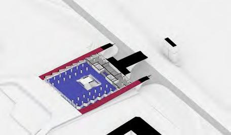
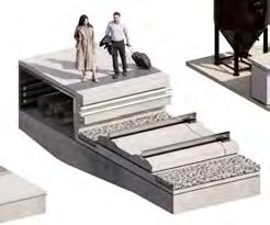
APPROACH: THE PROMENADE
Integration of and elevation of existing pedestrian infrastructure, making the station an active part of daily life.
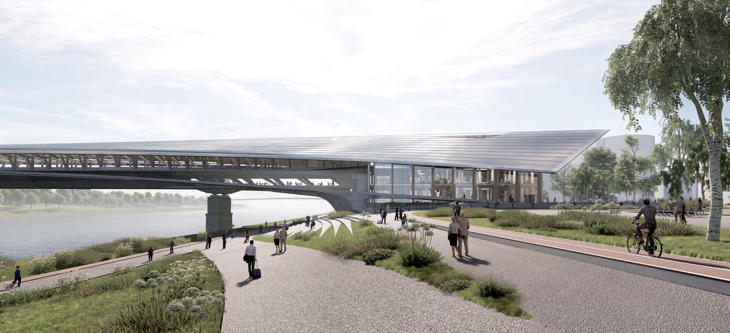
ENTRANCE
Aerial exploring the buffer zone between the station terminal and existing city infrastructure.
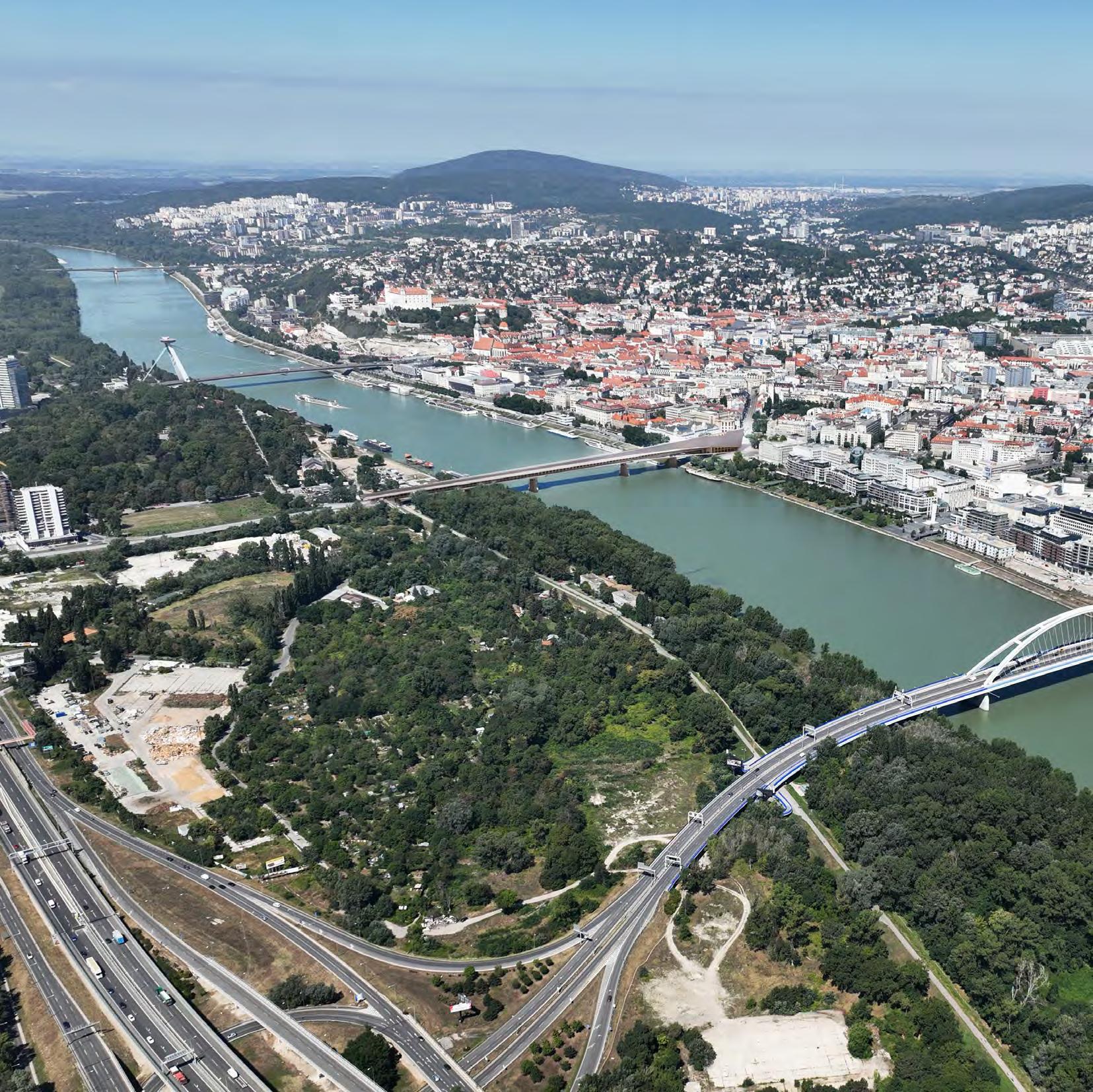
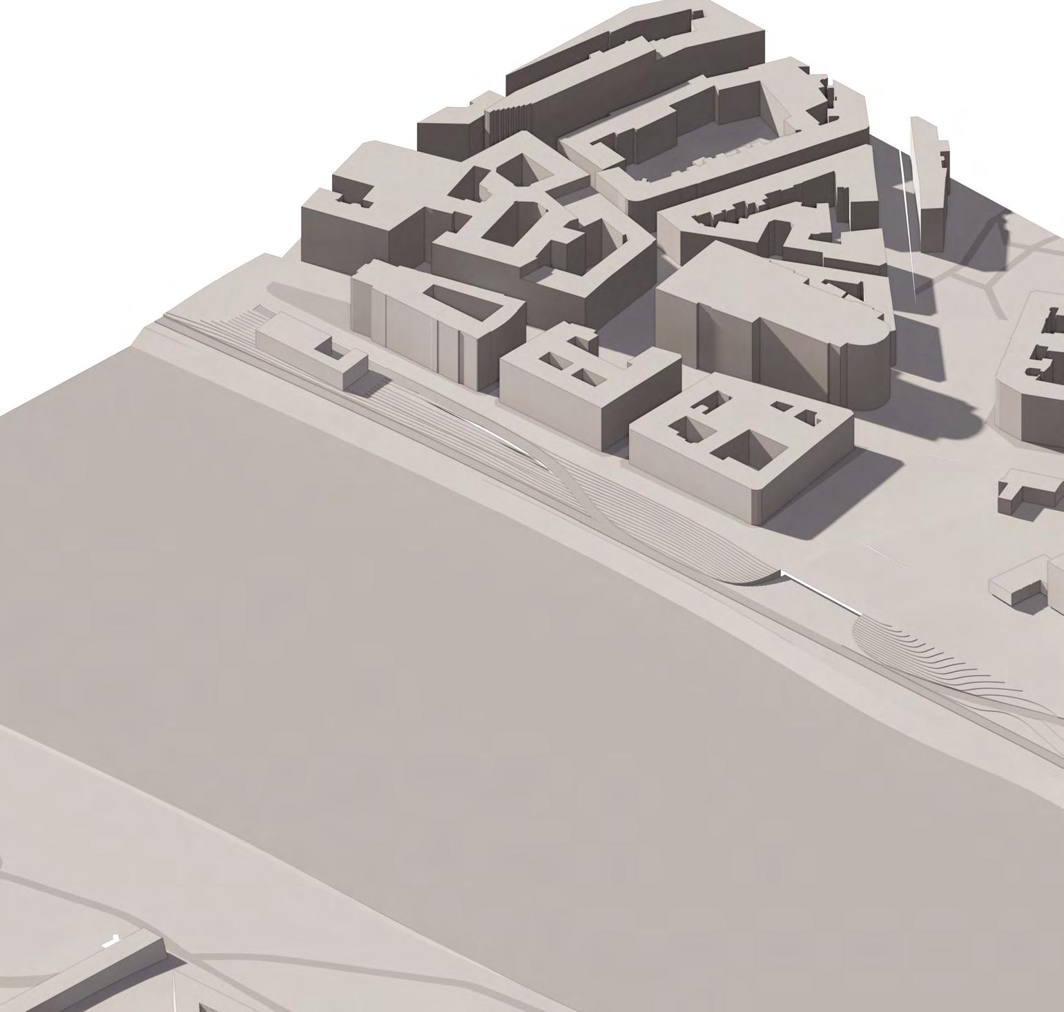
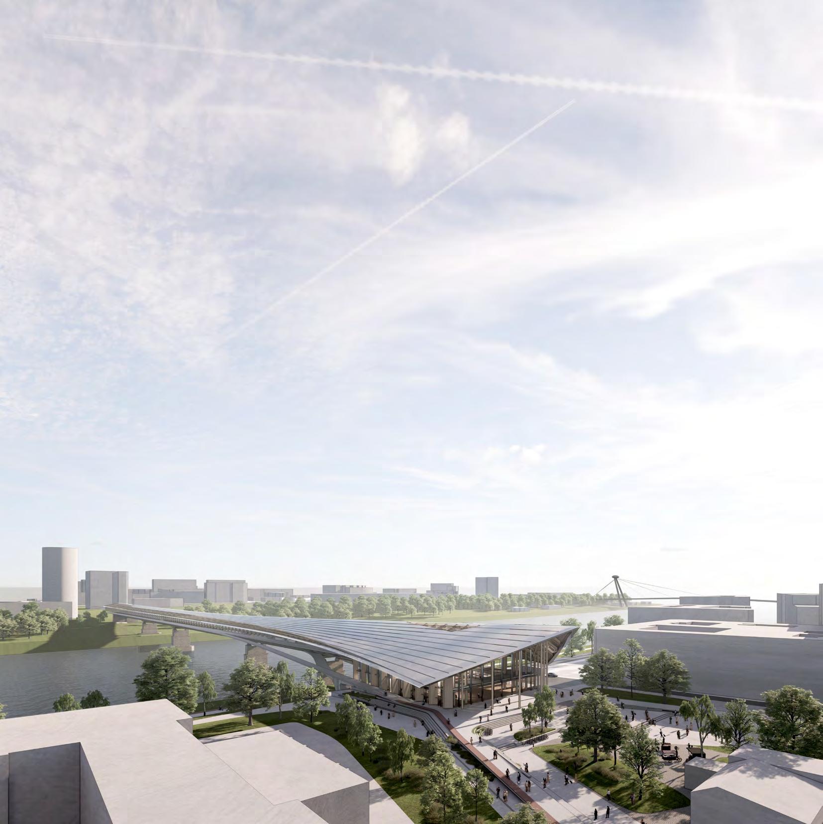
CITY BUILDING
Aerial view of Bratislava’s bridges and their different reactions to asnd relationships with the banks of the city center.
IV. APPENDIX
GENERAL ARRANGEMENT DRAWINGS
1. TERMINAL HALL WAITING AREAS
2.STATION PLATFORM CONCOURSE
3. STATION PLATFORMS
4. CYCLE STATION DOCK
5. PUBLIC PROMENADE
P2 P1 A1 F1 137.0 18.0 24.0 80.0 45.0 50.0 P2 P1 A1 F1 137.0 80.0 45.0 50.0 DESIGN PORTFOLIO | BRATISLAVA TERMINAL GENERAL ARRANGEMENT DRAWINGS LONG SECTION 1:1500 @ A3 DESIGN PORTFOLIO | BRATISLAVA TERMINAL
GENERAL ARRANGEMENT DRAWINGS 1:1500 @ A3 L02 PLAN 0 15 30 60 120 1.
3.
2.
P3 P4 A2 137.0 18.0 90.0 95.0 P3 P4 A2 137.0 90.0 95.0
1. TERMINAL HALL WAITING AREAS
2.STATION PLATFORM CONCOURSE
3. STATION PLATFORMS
4. CYCLE STATION DOCK
5. PUBLIC PROMENADE
DESIGN PORTFOLIO | BRATISLAVA TERMINAL
LONG SECTION - TERMINAL TO BRIDGE CONNECTION 1:500 @ A3
+135.0 m B01 +129.0 m B02 +143.0 m GF +148.0 m L01 +153.0 m L02 5.00 11 01 5.00 5.00 5.00 02 03 04 5.00 05 5.00 06 5.00 07 5.00 08 5.00 09 5.00 10 5.00 11 01 5.00 5.00 5.00 02 03 04 5.00 05 5.00 06 5.00 07 5.00 08 5.00 09 5.00 10 R1 R2 R3 R4 R5 R1 R2 R3 R4 R5 5.00 5.00 5.00 5.00 5.00 5.00 5.00 5.00 5.00 5.00
GENERAL ARRANGEMENT DRAWINGS
|
DESIGN PORTFOLIO
BRATISLAVA TERMINAL
GENERAL ARRANGEMENT DRAWINGS 1:1500 @
L02 PLAN 0 15 30 60 120
3.
A3
1.
2.
5.00 5.00 5.00 5.00 5.00 5.00 5.00 5.00 5.00 5.00 5.00 5.00 12 13 14 15 16 17 18 19 20 21 22 5.00 5.00 5.00 5.00 5.00 23 24 25 26 27 28 5.00 5.00 5.00 5.00 5.00 5.00 5.00 5.00 5.00 5.00 5.00 5.00 12 13 14 15 16 17 18 19 20 21 22 5.00 5.00 5.00 5.00 5.00 23 24 25 26 27 28
DESIGN PORTFOLIO | BRATISLAVA TERMINAL
1. TERMINAL HALL WAITING AREAS
2.STATION PLATFORM CONCOURSE
3. STATION PLATFORMS
4. CYCLE STATION DOCK
5. PUBLIC PROMENADE
END CROSS SECTION - BRIDGE CONDITIONS 1:500 @ A3
134m 16m 15m 5m 10m 7.8m 8.8m 7.5m 11.5m 7.5m 11.5m 23m 7.5m 7.5m 11.5m 11.5m 23m 38m 7.5m 7.5m 11.5m 11.5m 38m 134m 16m 15m 5m 10m 7.8m 8.8m 7.5m 11.5m 7.5m 11.5m 23m 7.5m 7.5m 11.5m 11.5m 23m 38m 7.5m 7.5m 11.5m 11.5m 38m 134m 16m 15m 5m 10m 7.8m 8.8m 7.5m 11.5m 7.5m 11.5m 23m 7.5m 7.5m 11.5m 11.5m 23m 38m 7.5m 7.5m 11.5m 11.5m 38m
GENERAL ARRANGEMENT
PIER CONDITION
GENERAL ARRANGEMENT
0 15 30 60 120
TERMINAL
DRAWINGS
DESIGN PORTFOLIO | BRATISLAVA TERMINAL 3.
DRAWINGS 1:1500 @ A3 L02 PLAN
1.
2.
TYPICAL CONDITION
134m 5m 14.5m 9m 4.5m 8m 7m 18m 6m 6m 7.5m 11.5m 11.5m 11.5m 6m 6m 11.5m 11.5m 7.5m 11.5m 23m 35m 134 m 134m 5m 14.5m 9m 4.5m 8m 7m 18m 6m 6m 7.5m 11.5m 11.5m 11.5m 6m 6m 11.5m 11.5m 7.5m 11.5m 23m 35m 134 m 134m 5m 14.5m 9m 4.5m 8m 7m 18m 6m 6m 7.5m 11.5m 11.5m 11.5m 6m 6m 11.5m 11.5m 7.5m 11.5m 23m 35m 134 m
1. TERMINAL HALL WAITING AREAS
2.STATION PLATFORM CONCOURSE
3. STATION PLATFORMS
4. CYCLE STATION DOCK
5. PUBLIC PROMENADE
DESIGN PORTFOLIO | BRATISLAVA TERMINAL GENERAL ARRANGEMENT DRAWINGS DESIGN PORTFOLIO CITY CONTEXT 1:5000 @ A3 050 100 200 300 DESIGN PORTFOLIO | BRATISLAVA TERMINAL
GENERAL ARRANGEMENT DRAWINGS 1:1500 @ A3 L02 PLAN 0 15 30 60 120
3.
1.
2.
1. MEP + BOH
1. TERMINAL HALL WAITING AREAS
2. ADMIN + SUPPORT
2.STATION PLATFORM CONCOURSE
3. STATION PLATFORMS
3. RIVERSIDE TICKET HALL
4. WC’s
4. CYCLE STATION DOCK
5. PUBLIC PROMENADE
5. MEP + BOH
01 5.00 5.00 5.00 02 03 04 5.00 05 5.00 06 5.00 07 5.00 08 5.00 09 01 5.00 5.00 5.00 02 03 04 5.00 05 5.00 06 5.00 07 5.00 AB C 3.00 5.00 F GH 24.00 5.00 3.00 08 5.00 09 + 135.0 m DESIGN PORTFOLIO | BRATISLAVA TERMINAL GENERAL ARRANGEMENT DRAWINGS DESIGN PORTFOLIO 1:500 @ A3 B01PLAN 05 10 20 40 1.
2. 3.4. DESIGN PORTFOLIO | BRATISLAVA TERMINAL 3. GENERAL ARRANGEMENT DRAWINGS 1:1500 @ A3 L02 PLAN 0 15 30 60 120 1.
2.
09 5.00 10 AB C D E 3.00 5.00 F GH 8.00 8.00 8.00 5.00 3.00 09 5.00 10 + 135.0 m 5.
1. TERMINAL HALL WAITING AREAS
1. TERMINAL HALL CONCOURSE
2.STATION PLATFORM CONCOURSE
2. TICKETS + INFORMATION
3. WC’s
3. STATION PLATFORMS
4. CYCLE STATION DOCK
4. BOH + ADMIN
5. PUBLIC PROMENADE
+ 143.0 m + 143.0 m + 142.0 m + 141.0 m 01 5.00 5.00 5.00 02 03 04 5.00 05 5.00 06 5.00 07 5.00 08 5.00 09 01 5.00 5.00 5.00 02 03 04 5.00 05 5.00 06 5.00 07 5.00 AB C 3.00 5.00 F GH 24.00 5.00 3.00 08 5.00 09 DESIGN PORTFOLIO | BRATISLAVA TERMINAL GENERAL ARRANGEMENT DRAWINGS 1:500 @ A3 GF PLAN 05 10 20 40 1.
2. 3.
DESIGN PORTFOLIO | BRATISLAVA TERMINAL
GENERAL ARRANGEMENT DRAWINGS 1:1500 @ A3 L02 PLAN 0 15 30 60 120 1.
3.
3.
2.
+ 142.0 m + 141.0 m + 135.5 m 09 5.00 10 AB C D E 3.00 5.00 F GH 8.00 8.00 8.00 5.00 3.00 09 5.00 10 4.
1. TERMINAL HALL WAITING AREAS
1. TERMINAL HALL LOUNGE AREAS
2.BEER HALL
2.STATION PLATFORM CONCOURSE
3. WC’s
3. STATION PLATFORMS
4. CYCLE STATION DOCK
4. BOH + STORAGE
5. PUBLIC PROMENADE
5. ENCLOSED CYCLE-LANE
01 5.00 5.00 5.00 02 03 04 5.00 05 5.00 06 5.00 07 5.00 08 5.00 09 01 5.00 5.00 5.00 02 03 04 5.00 05 5.00 06 5.00 07 5.00 AB C 3.00 5.00 F GH 24.00 5.00 3.00 08 5.00 09 + 148.0 m DESIGN PORTFOLIO | BRATISLAVA TERMINAL GENERAL ARRANGEMENT DRAWINGS 1:500 @ A3 L01PLAN 05 10 20 40
1.
DESIGN PORTFOLIO | BRATISLAVA TERMINAL
3.
GENERAL ARRANGEMENT DRAWINGS 1:1500 @ A3 L02 PLAN 0 15 30 60 120
3.
1.
2.
09 5.00 5.00 7.85 10.00 10.00 10.00 10.00 12.5 7.85 10.00 10.00 10.00 10.00 12.5 5.00 5.00 5.00 5.00 5.00 10 11 X1 X2 X3 X4 X5 23 24 25 26 27 28 5.00 5.00 5.00 5.00 5.00 5.00 11 X1 X2 X3 X4 X5 23 24 25 26 27 28 AB C D E 3.00 5.00 F GH 8.00 8.00 8.00 5.00 3.00 09 5.00 10 2.
4. 6.
1. TERMINAL HALL WAITING AREAS
1. TERMINAL HALL WAITING AREAS
2.STATION PLATFORM CONCOURSE
2.STATION PLATFORM CONCOURSE
3. STATION PLATFORMS
3. STATION PLATFORMS
4. CYCLE STATION DOCK
4. CYCLE STATION DOCK
5. PUBLIC PROMENADE
5. PUBLIC PROMENADE
01 5.00 5.00 5.00 02 03 04 5.00 05 5.00 06 5.00 07 5.00 08 5.00 09 01 5.00 5.00 5.00 02 03 04 5.00 05 5.00 06 5.00 07 5.00 AB C 3.00 5.00 F GH 24.00 5.00 3.00 08 5.00 09 DESIGN PORTFOLIO | BRATISLAVA TERMINAL GENERAL ARRANGEMENT DRAWINGS 1:500 @ A3 L02 PLAN 05 10 20 40
1.
DESIGN PORTFOLIO | BRATISLAVA TERMINAL
GENERAL ARRANGEMENT DRAWINGS 1:1500 @ A3 L02 PLAN 0 15 30 60 120
3.
1.
2.
09 5.00 5.00 5.00 5.00 5.00 5.00 5.00 5.00 5.00 5.00 5.00 5.00 5.00 5.00 5.00 5.00 5.00 5.00 5.00 10 11 12 13 14 15 16 17 18 19 20 21 22 5.00 5.00 5.00 5.00 5.00 5.00 5.00 5.00 5.00 5.00 5.00 5.00 12 13 14 15 16 17 18 19 20 21 22 23 24 25 26 27 28 5.00 5.00 5.00 5.00 5.00 5.00 11 23 24 25 26 27 28 AB C D E 3.00 5.00 F GH 8.00 8.00 8.00 5.00 3.00 09 5.00 10 + 153.0 m
5.
3. 4.
2.
1. TERMINAL HALL WAITING AREAS
1. TERMINAL HALL WAITING AREAS
2.STATION PLATFORM CONCOURSE
2.STATION PLATFORM CONCOURSE
3. STATION PLATFORMS
3. STATION PLATFORMS
4. CYCLE STATION DOCK
4. CYCLE STATION DOCK
5. PUBLIC PROMENADE
5. PUBLIC PROMENADE
DESIGN PORTFOLIO | BRATISLAVA TERMINAL
GENERAL ARRANGEMENT DRAWINGS 1:1500 @ A3 L02 PLAN 0 15 30 60 120
3.
1.
DESIGN PORTFOLIO | BRATISLAVA TERMINAL
2.
GENERAL ARRANGEMENT DRAWINGS 1:1500 @ A3 L02 PLAN 0 15 30 60 120
3.
1.
2.
4. 5.
IV. APPENDIX
SEMESTER I. ARTIFACT ANALYSIS
FRAGMENT EXPERIMENTATION
ARTEFACT ANALYSIS
VERNACULAR TIMBER CONSTRUCTION CONTEXT
PROTECTED
41% of Slovakia’s wooded
Cross-lap intersection
Parallel circulation fusion to double height interface
Perpendicular penetration to double height interface
Timber
Ridge purlin
Gabled roof often clad with vertical planks
Perpendicular penetration through double height space
Diagonal penetration through double height space
Roof battens Often notched directly onto roof rafters

Roof overhanging eaves Creates protected circulation around building perimeter and kept rain away from facade
Cross-lap penetration through double height space
Perimeter up-stand
Made of stone or masonry, the raised foundation was particularly useful in uneven, mountainous terrain
BRATISLAVA TERMINAL
Double cross-lap penetration through double height
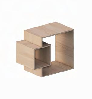
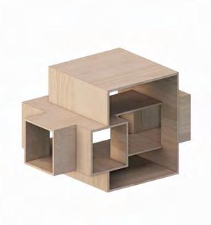
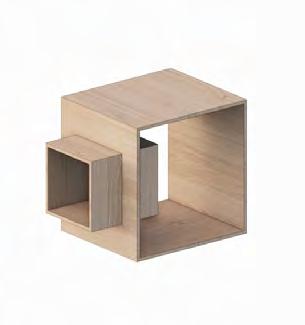
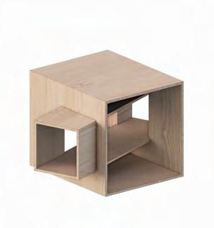
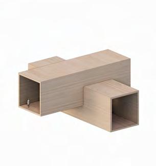
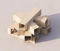
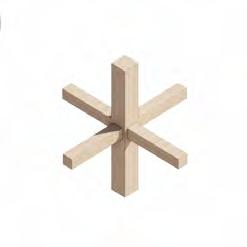
VOLUMETRIC INTERSECTIONS
Corner half-lap intersection
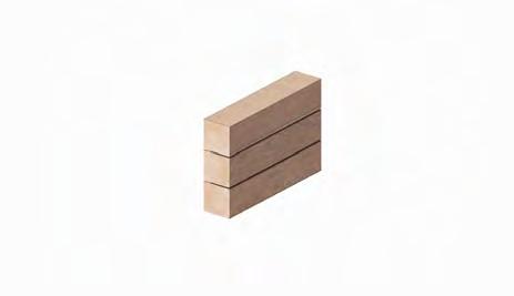
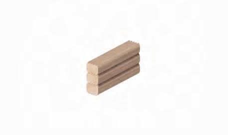
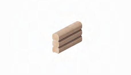
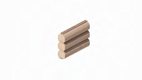
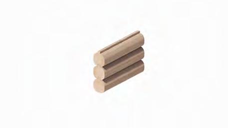
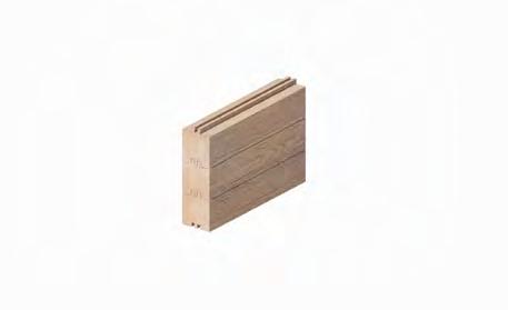
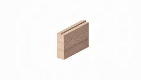
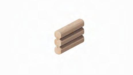
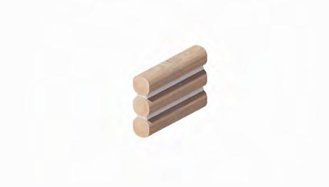
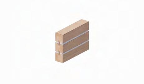
In stacked log construction the key areas of offering stability are notches created in corner conditions when different walls meet. To increase the stability of the whole system additional support can be offered by locking the logs in place along their entire length with different types of grooving. As the timber dries it sets into place strengthening the connection of the groves .
VERNACULAR TIMBER CONSTRUCTION
Historically located at the center of changing methods were greatly influenced by, and became trends. The case study is an archetypal log mountain areas and protected villages such
Inspired Central connect volumes VOLUMETRIC
PROTECTED ZONES UNPROTECTED ZONES
|
DESIGN PORTFOLIO | BRATISLAVA TERMINAL ARTEFACT ANALYSIS
FRAGMENT EXPERIMENTATION
Timber roof rafter
I. Flat on flat
IV. Round on round with chinking
II. Flat on flat with spline
V. Round on round with spline
III. Flat on flat with corner support
VI. Round on round with corner support
VII. Single tongue and grove
X. Double tongue and grove XI. Round double tongue and groveXII. Round on round with groove
VIII. Round single tongue and grove IX. Round on round with saddle
|
STACKED LOG CONSTRUCTION TYPES DESIGN PORTFOLIO |
Analysis of spatial relationships created by intersecting of volumes in various configurations. From corner intersections to volume penetrations the study looks at the interface of single and double height spaces.
Stepped perpendicular half-lap intersection
PROTECTED FORESTS
Slovakia’s land coverage are forests and areas.
Roof tie beam
Often times two logs spliced together depending on building depth
Timber roof joist
Roof corner
Interlocking shingles
Most often hand hewn from larch or spruce, in Slovak šindeľ
Roof truss post
Timber plank flooring
Roof edge beam sill
Interlocking notch connection on external walls corner
Timber floor joists
Often sat directly on rammed earth with an air gap acting as insulation
Roof beam notch
Beams directly attach onto external wall elements by notching, increasing the stability of the interlocking frame
Hand hewn logs
Main walls most often from softwood like spruce, hand hewn into rectangular profiles or in older houses left round. Gaps between logs were stuffed with moss or straw to help with thermal performance.
Edge beams joined by half lap or cross lap connection
CONSTRUCTION IN SLOVAKIA
changing spheres of influence, traditional Slovak construction became a fusion of Slavic, Eastern-European, Germanic house found across central and eastern Slovakia in such as W or Vlkolínec.
Roof to wall connection
Wall logs extend outwards and interlock creating a bracket system supporting the roof edge beams
House scale
The scale of the houses was modest in length often dictated by the length of a trunk to avoid splicing of components. For this reason the houses expanded in length, adding smaller rooms for domestic or utilitarian use.
5m Bedroom Kitchen Storage 2.5m 4m
Cross-lap intersection
Parallel circulation fusion to double height interface
I. Roof edge beams
Beams overlap in roof corners, joined by cross lap connection allowing them to protrude
II. Roof to wall connection
Wall logs extend outwards, interlock and stack up with a cross lap creating a bracket system which supports the roof edge beams
Perpendicular penetration to double height interface
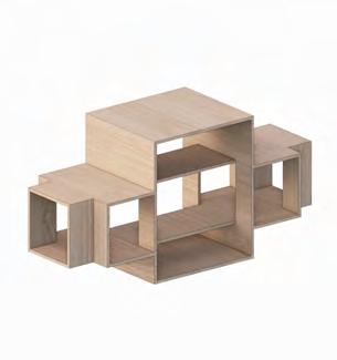
Perpendicular penetration through double height space
Diagonal penetration through double height space
Cross-lap penetration through double height space
III. Perimeter up-stand
The base logs of the wall structure are anchored into the stone up-stand with timber members.
Double cross-lap penetration through double height
Stepped perpendicular half-lap intersection
CORNER CONDITION
VOLUMETRIC INTERSECTIONS
Analysis of spatial relationships created by intersecting of volumes in various configurations. From corner intersections to volume penetrations the study looks at the interface of single and double height spaces.
The roof edge beams overlap in roof corners, joined by cross lap connections allowing them to protrude. They are supported by the timber bracketry composed of extended wall logs towards the top of the walls. The stepping varies from house to house but most typically consist of four beams. These are typically also connected by cross lap joints to allow for protrusions. The base logs of the wall structure are anchored into the stone up-stand.
DESIGN PORTFOLIO | BRATISLAVA TERMINAL
ANALYSIS | FRAGMENT EXPERIMENTATION
ARTEFACT
II.
I.
DESIGN PORTFOLIO |
| FRAGMENT EXPERIMENTATION
BRATISLAVA TERMINAL ARTEFACT ANALYSIS
Corner half-lap intersection
Inspired Central connect volumes VOLUMETRIC
structure are with
CORNER NOTCH TYPES
I. Saddle Notch Interlocking of full logs without hewing, creating the simplest and fastest method of log construction. It is believed to be the oldest of methods due to it’s simplicity.
II. Box Notch The simplest hewed approach, relying on the addition of a vertical timber pin to lock all the elements in place for stability of whole system.

III. Dovetail Notch Probably the most common of connections although variation in profile angles is common. Angling offers additional stability to the frame particularly against torsion.
IV. Locked / Tooth-edge Notch This system offers further stability to the frame, as the profiles lock into each other firmly. It is however more complex to hew and so is rarer than the others.
interlock creating joined them
I. Saddle Notch
II. Box Notch
III. Dovetail Notch
IV. Locked/Tooth-edge Notch
ARTEFACT ANALYSIS
ARTEFACT ANALYSIS
Cross-lap intersection
Parallel circulation fusion to double height interface
Perpendicular penetration to double height interface
CROSS LAP CONNECTIONS
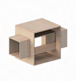
Perpendicular penetration through double height space
Diagonal penetration through double height space
Cross-lap penetration through double height space
I. Half-Lap
Double cross-lap penetration through double height
VOLUMETRIC INTERSECTIONS
Corner half-lap intersection
Analysis of spatial relationships created by intersecting of volumes in various configurations. From corner intersections to volume penetrations the study looks at the interface of single and double height spaces.
SPLICE CONNECTIONS
Stepped perpendicular half-lap intersection
Inspired Central connect volumes VOLUMETRIC
DESIGN PORTFOLIO | BRATISLAVA TERMINAL | FRAGMENT EXPERIMENTATION
III. Under Squinted Half-Lap
V. Under Squinted Stop Splayed with Table
II. Half-Lap With Table
IV. Under Squinted Stop Splayed Half-Lap
II. Stop Bladed with Cogs
I. Flush Cross-Lap II. Cross-Lap III. Curved Cross-Lap
IV. Mitered Half-Lap
V. Dove-Tail Half-Lap
|
VI. Half-Lap | FRAGMENT EXPERIMENTATION
DESIGN PORTFOLIO
BRATISLAVA TERMINAL
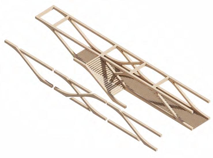
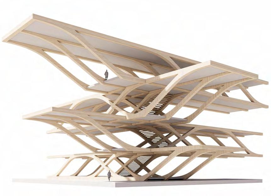
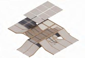
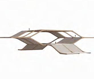
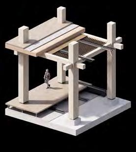
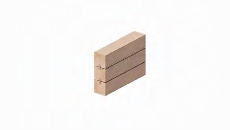
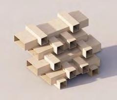
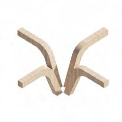
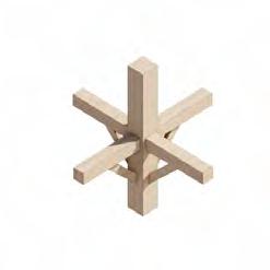
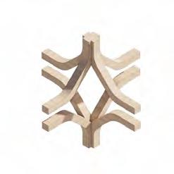
STRUCTURAL STACKING: UNRAVELING OF VERNACULAR CORNER CONDITION
Taking the traditional wall to roof interface condition of Slovak log-construction and unraveling it by increasing the spacing between horizontal elements vertically as well as gradually increasing the cantilever of the top elements.
Cross-lap intersection
Parallel circulation fusion to double height interface
Perpendicular penetration to double height interface
Perpendicular penetration through double height space
Diagonal penetration through double height space
Cross-lap penetration through double height space
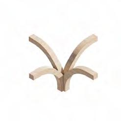
I. Creation of single component from curved lamellas to achieve desired shape
II. Splitting component into core of without curvature and additional stepped curved lamellas
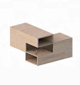
Double cross-lap penetration through double height
VOLUMETRIC INTERSECTIONS
Corner half-lap intersection
VOLUMETRIC STACKING: SCALING OF CORNER CONDITION
Analysis of spatial relationships created by intersecting of volumes in various configurations. From corner intersections to volume penetrations the study looks at the interface of single and double height spaces.
Stepped perpendicular half-lap intersection
III. Fusion of horizontal beam structure with slanting components while maintaining the curvature of the diagonal member
Scaling the analysed cantilevering corner condition to a full building level allows for a study of the potential spatial opportunities the system offers. Due to the nature of the material chosen the structural principles and tectonic change significantly, pushing the direction towards more contemporary timber solutions such as lamination in glulam and baubuche solutions.
DESIGN PORTFOLIO |
ARTEFACT ANALYSIS | FRAGMENT EXPERIMENTATION
BRATISLAVA TERMINAL
I. Scaled up notch corner condition
II. Simple truss construction
III. Fused horizontal and vertical structure
IV. Maintaining dynamic directionality
DESIGN
|
|
EXPERIMENTATION
PORTFOLIO
BRATISLAVA TERMINAL ARTEFACT ANALYSIS
FRAGMENT
Inspired Central connect volumes VOLUMETRIC
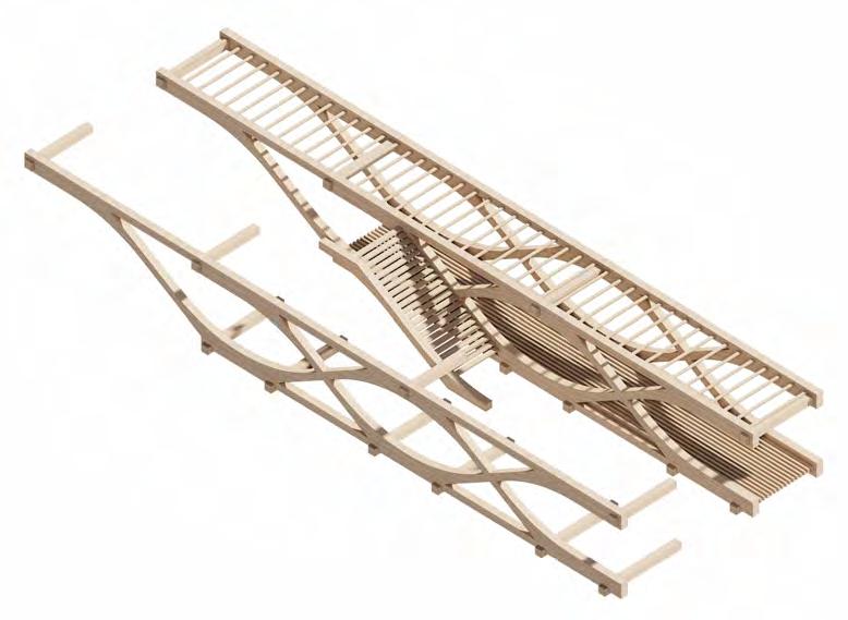
Addition of horizontal structural elements to proposed framework to support frame rigidity in the form of interlocking horizontal members
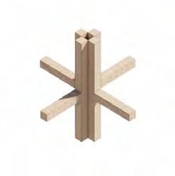
STRUCTURAL INTERLOCKING THROUGH STACK
Following key principles of lafting, by creating vertical structure without the use of vertical components like columns. Addition of horizontal structural elements to proposed framework to support frame rigidity in the form of interlocking horizontal members. Avoiding placement of columns by fusing horizontal and vertical structure.
Addition of secondary horizontal elements to tie into frame finishing, services integration and fragment skin
corner condition construction and vertical structure
dynamic directionality Creation of single component from curved to achieve shape Splitting component core of without curvature and additional stepped curved lamellas Fusion of horizontal structure with slanting components maintaining curvature of the diagonal member
BRATISLAVA
Cross-lap intersection
Cross-lap intersection
Parallel circulation fusion to double height interface
Parallel circulation fusion to double height interface
Perpendicular penetration to double height interface
Perpendicular penetration to double height interface
Perpendicular penetration through double height space
Perpendicular penetration through double height space
Diagonal penetration through double height space
Diagonal penetration through double height space
Cross-lap penetration through double height space
Cross-lap penetration through double height space
Double cross-lap penetration through double height
Double cross-lap penetration through double height
VOLUMETRIC INTERSECTIONS
VOLUMETRIC INTERSECTIONS
Corner half-lap intersection
Corner half-lap intersection
Analysis of spatial relationships created by intersecting of volumes in various configurations. From corner intersections to volume penetrations the study looks at the interface of single and double height spaces.
Analysis of spatial relationships created by intersecting of volumes in various configurations. From corner intersections to volume penetrations the study looks at the interface of single and double height spaces.
Stepped perpendicular half-lap intersection
Stepped perpendicular half-lap intersection
|
| FRAGMENT EXPERIMENTATION
DESIGN PORTFOLIO
BRATISLAVA TERMINAL ARTEFACT ANALYSIS
DESIGN PORTFOLIO |
| FRAGMENT EXPERIMENTATION
TERMINAL ARTEFACT ANALYSIS
Inspired Central connect volumes VOLUMETRIC
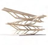
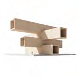
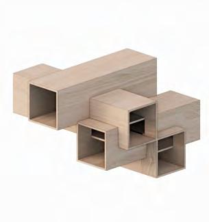
NEST STACK
double double
ORTHOGONAL STEPPED STACK
INTERSECTING CIRCULATION
VOLUMETRIC STACKING
Inspired by the Vitra House by Herzog De Meuron, Habitat 67 by Roberto Conte and Tallin Central Train Station by ZHA this study looks at volumetric intersections creating visually connect half levels, external terraces, circulation routes cutting through double-height volumes and bridging conditions often seen in infrastructural typologies.
half-lap
DIAGONAL
II. REMOVAL OF VERTICAL STRUCTURE
II. REMOVAL OF VERTICAL STRUCTURE
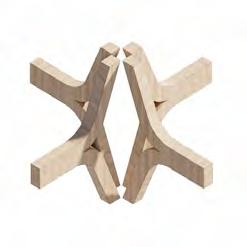
STRUCTURAL FUSION
STRUCTURAL FUSION
Following the principles of structural stacking the attempt is to either fuse horizontal and vertical structure or to over-scale diagonal bracketry to remove vertical elements. The principles aim to reduce the amount of connection points in one place, but rather spread them around decreasing the potential for structural failure in single point within the frames.
Following the principles of structural stacking the attempt is to either fuse horizontal and vertical structure or to over-scale diagonal bracketry to remove vertical elements. The principles aim to reduce the amount of connection points in one place, but rather spread them around decreasing the potential for structural failure in single point within the frames.
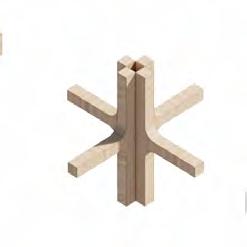
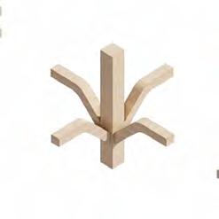
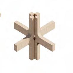
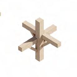
DESIGN PORTFOLIO | BRATISLAVA TERMINAL
I. FUSION OF COLUMN AND BEAM
ARTEFACT ANALYSIS | FRAGMENT EXPERIMENTATION DESIGN PORTFOLIO | BRATISLAVA TERMINAL
tree
OVERPASS
MULTI-DIRECTIONAL This condition under-pass direction
circulation
I. FUSION OF COLUMN AND BEAM
ARTEFACT ANALYSIS | FRAGMENT EXPERIMENTATION
MULTI-DIRECTIONAL OVERPASSOVERPASS - UNDERPASS NODE
OVERPASS STUDY: MULTI-LEVEL CIRCULATION
This condition looks at the possibility of simultaneously being able to under-pass and over-pass from the same location. Staggering the staircase direction can allow for easy access to both types of circulations, connecting tree circulation corridors at different levels.
MULTI-LEVEL CIRCULATION NODE
All work produced by Unit 14
Unit book design by Charlie Harriswww.bartlett.ucl.ac.uk/architecture
Copyright 2021
The Bartlett School of Architecture, UCL All rights reserved.
No part of this publication may be reproduced or transmited in any form or by any means, electronic or mechanical, including photocopy, recording or any information storage and retreival system without permission in writing from the publisher.

-

@unit14_ucl UNIT
CONSTRUCTED FUTURES 2023
At the center of Unit 14’s academic exploration lies Buckminster Fuller’s ideal of the ‘The Comprehensive Designer’, a master-builder that follows Renaissance principles and a holistic approach. Fuller referred to this ideal of the designer as somebody who is capable of comprehending the ‘integrateable significance’ of specialised findings and is able to realise and coordinate the commonwealth potentials of these discoveries while not disappearing into a career of expertise. Like Fuller, we are opportunists in search of new ideas and their benefits via architectural synthesis. As such Unit 14 is a test bed for exploration and innovation, examining the role of the architect in an environment of continuous change. We are in search of the new, leveraging technologies, workflows and modes of production seen in disciplines outside our own. We test ideas systematically by means of digital as well as physical drawings, models and prototypes. Our work evolves around technological speculation with a research-driven core, generating momentum through astute synthesis. Our propositions are ultimately made through the design of buildings and through the in-depth consideration of structural formation and tectonic. This, coupled with a strong research ethos, will generate new and unprecedented, one day viable and spectacular proposals. They will be beautiful because of their intelligence - extraordinary findings and the artful integration of those into architecture.
The focus of this year’s work evolves around the concept of ‘Constructed Futures’. The term aims to describe architecture and as such fundamentally human future as the result of the architect’s highest degree of synthesis of underlying principles. Constructional logic, spatial innovation, typological organisation, environmental and structural performance are all negotiated in a highly iterative process driven by intense architectural investigation. Inspiration for inherent principles of organisational intelligence can be observed in both biotic and abiotic systems, in all spatial arrangements where it is critical for the overall performance of the developed order. Through the deep understanding of constructional principles, we will generate highly developed architectural systems of unencountered intensity where spatial organisation arises as a result of sets of mutual interactions. Observation as well as re-examination of civilisatory developments will enable us to project near future scenarios and position ourselves as avant-garde in the process of designing a comprehensive vision for the forthcoming. The projects will take shape as research based imaginative tales, architectural visions driven by speculation.
Thanks to: ARUP, ALA, DKFS, knippershelbig, RSHP, HASSELL, Seth Stein Architects, ZHA, Expedition Engineering

All work produced by Unit 14
Unit book design by Charlie Harris
www.bartlett.ucl.ac.uk/architecture
Copyright 2021 The Bartlett School of Architecture, UCL All rights reserved. -

UNIT 14 @unit14_ucl
No part of this publication may be reproduced or transmitted in any form or by any means, electronic or mechanical, including photocopy, recording or any information storage and retreival system without permission in writing from the publisher.
