Kei Käppeler_Y5 | Unit 14 | Bartlett School of Architecture
All work produced by Unit 14 Cover design by Charlie Harris
https://www.ucl.ac.uk/bartlett/architecture
Copyright 2025 The Bartlett School of Architecture, UCL All rights reserved.
No part of this publication may be reproduced or transmitted in any form or by any means, electronic or mechanical, including photocopy, recording or any information storage and retrieval system without permission in writing from the publisher.
@unit14_ucl
kk@unitaarch.de
@keikaeppeler
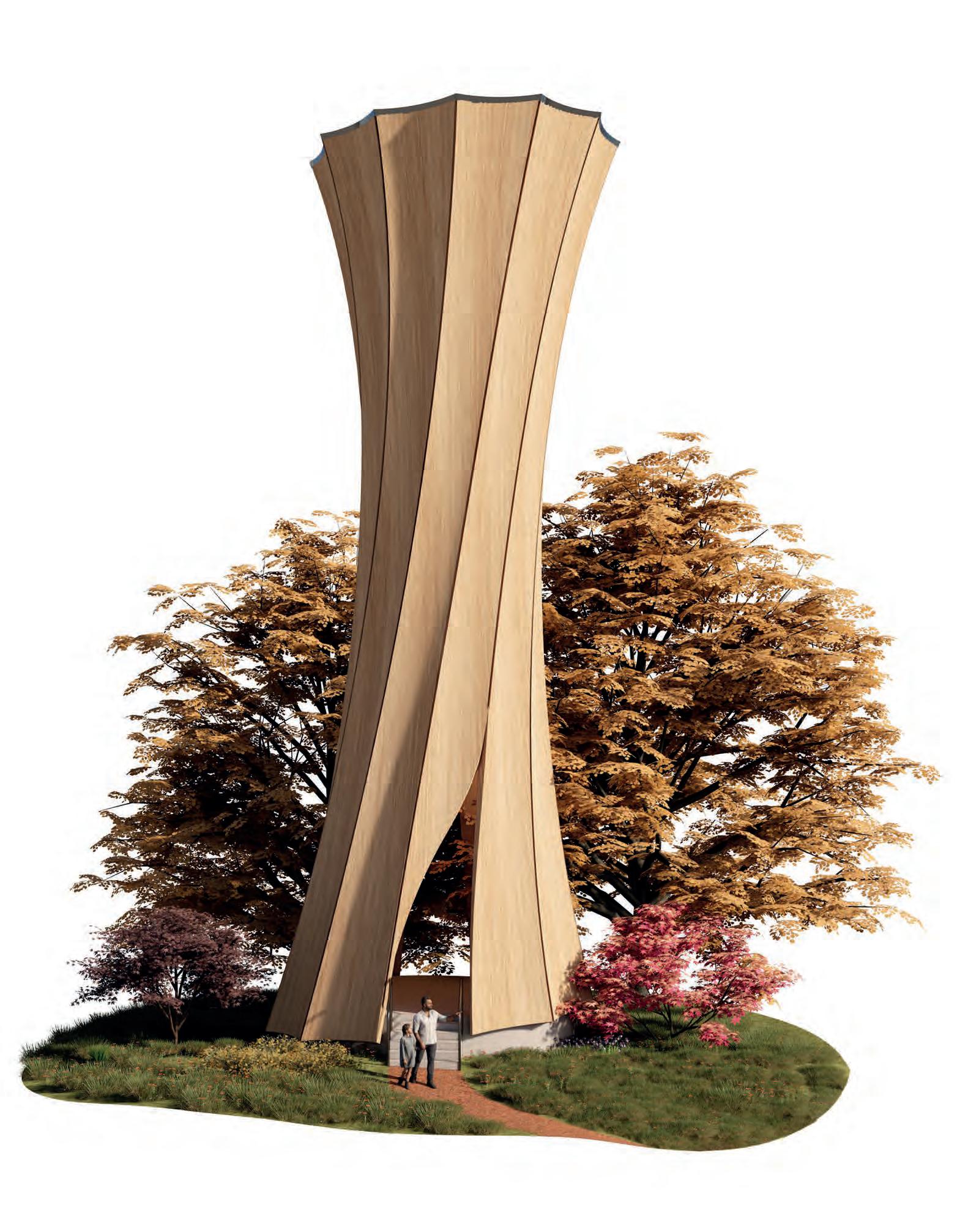
STUTTGART STADIUM
REIMAGINING STADIUM ARCHITECTURE THROUGH BENT TIMBER SURFACES
Stuttgart, Germany
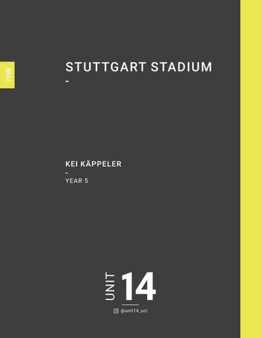
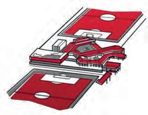
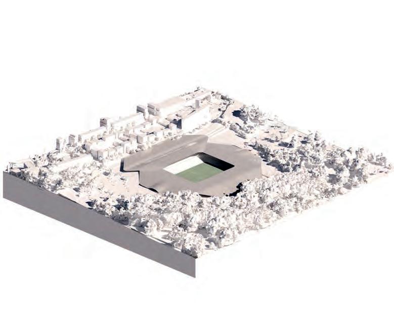
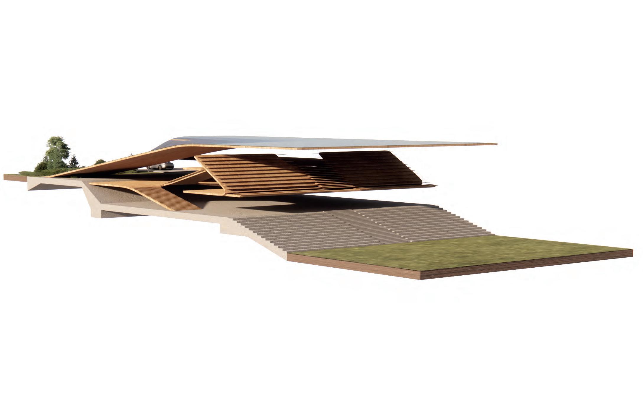
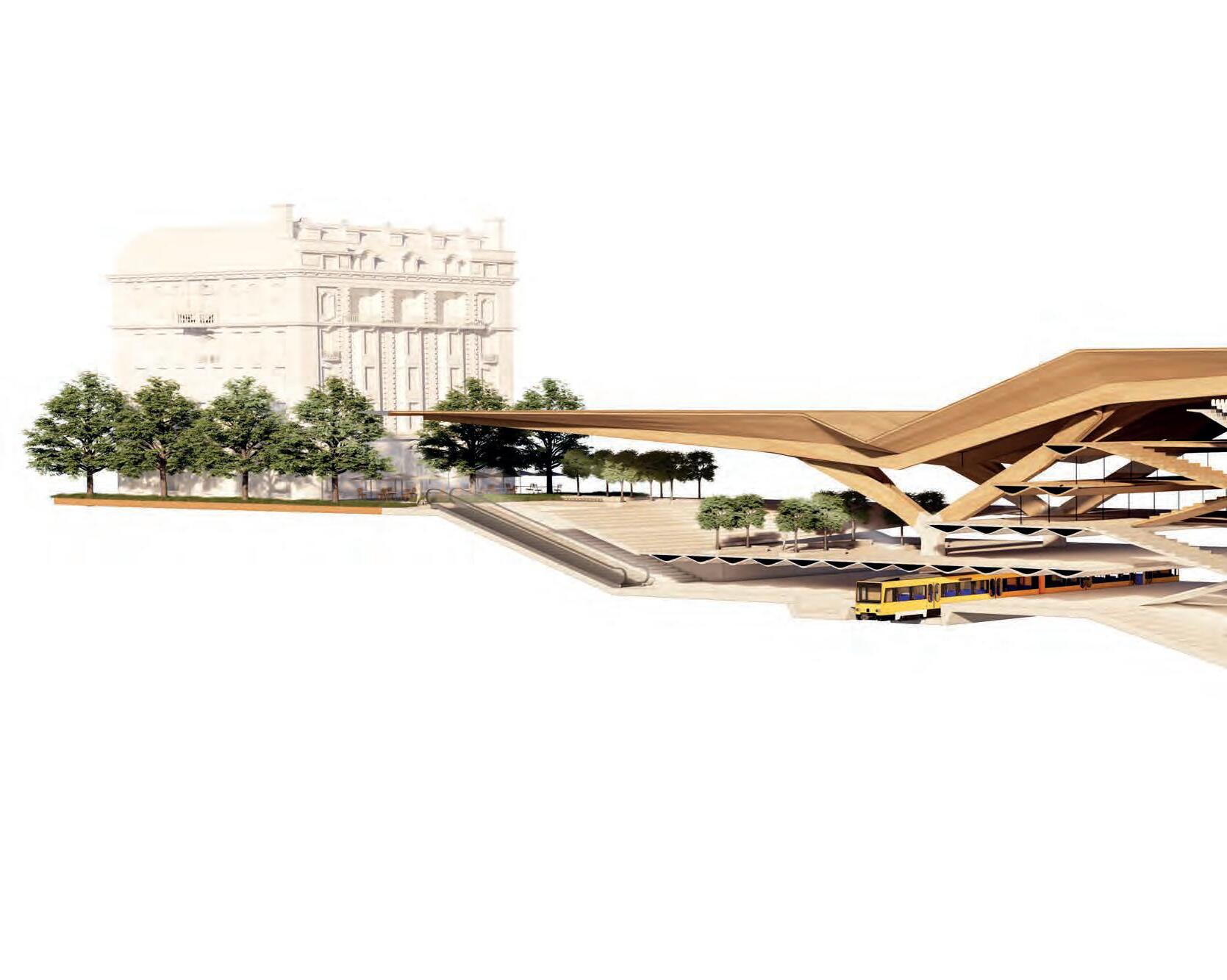
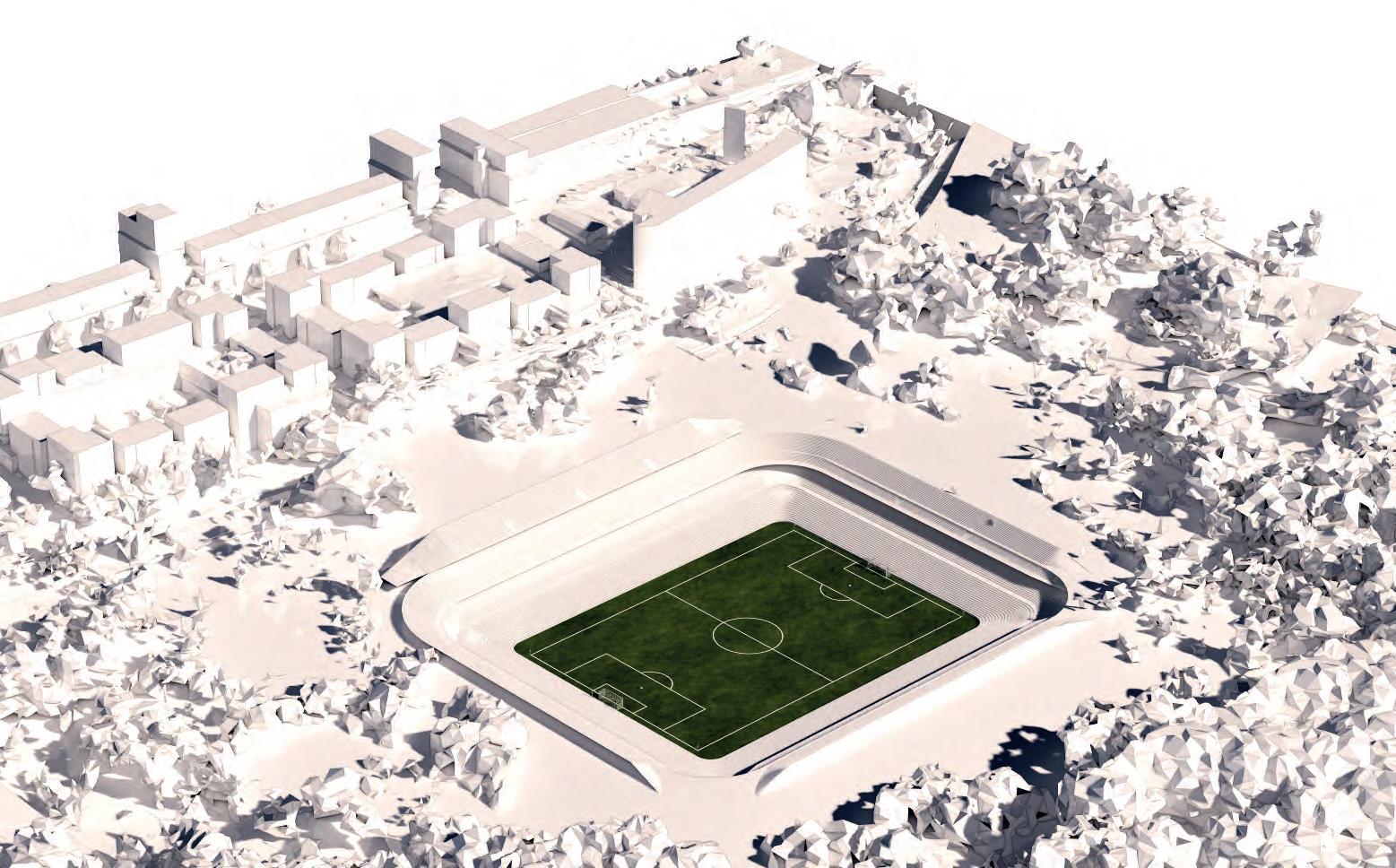
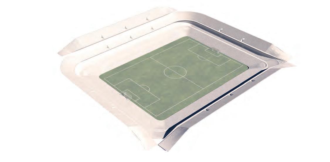
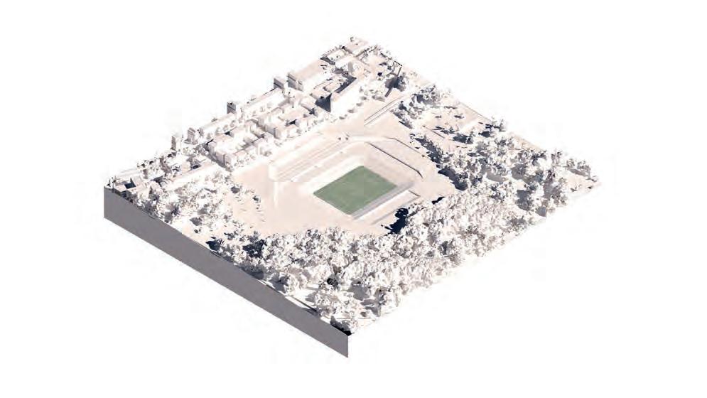
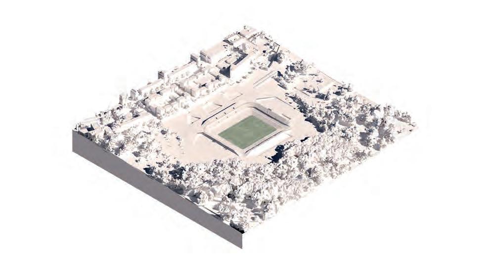
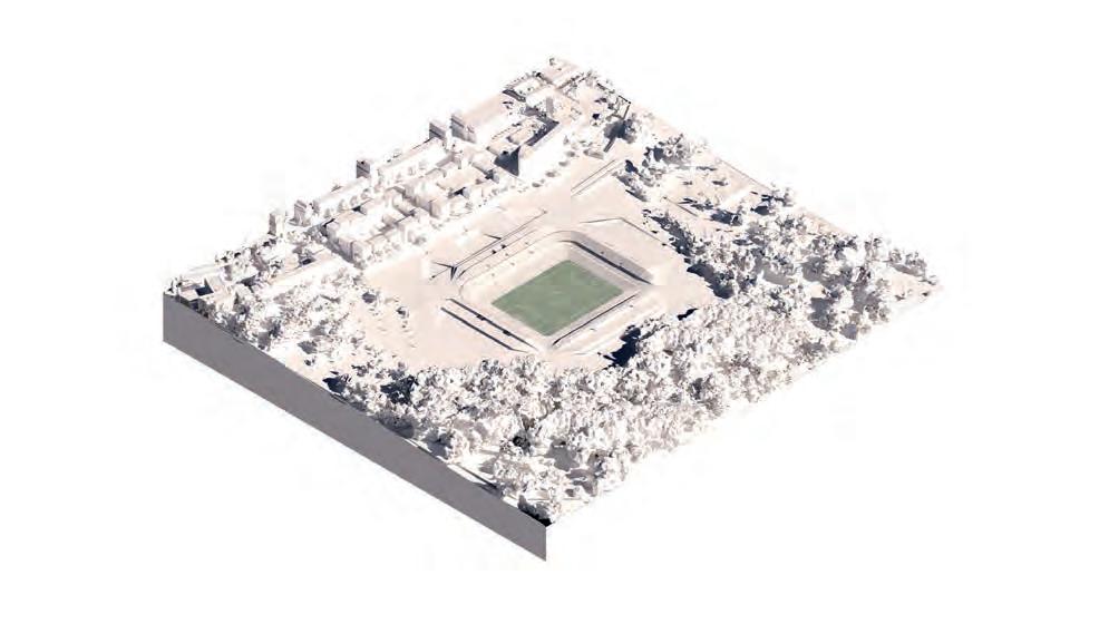
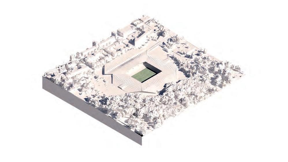
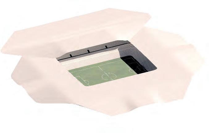
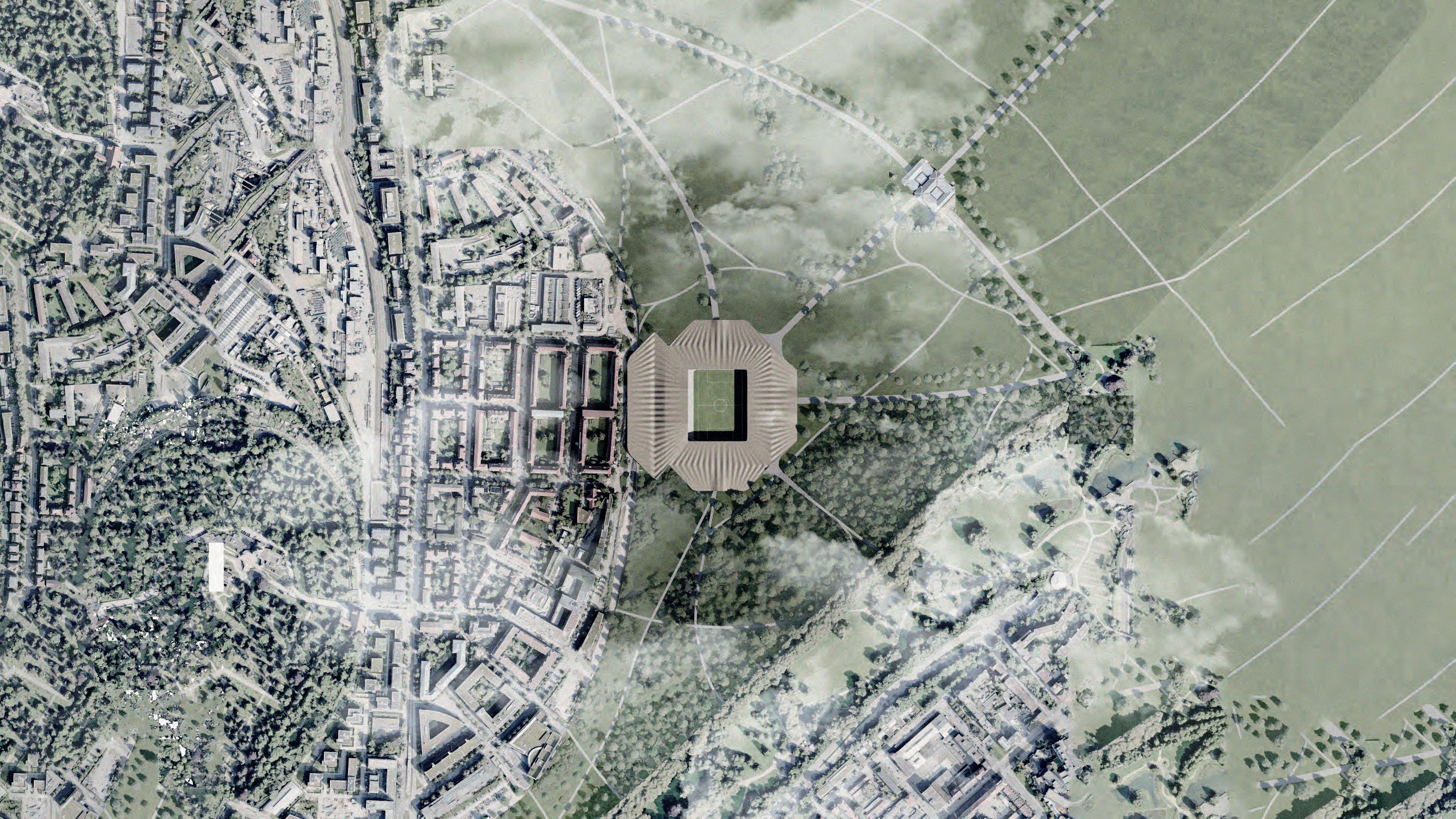
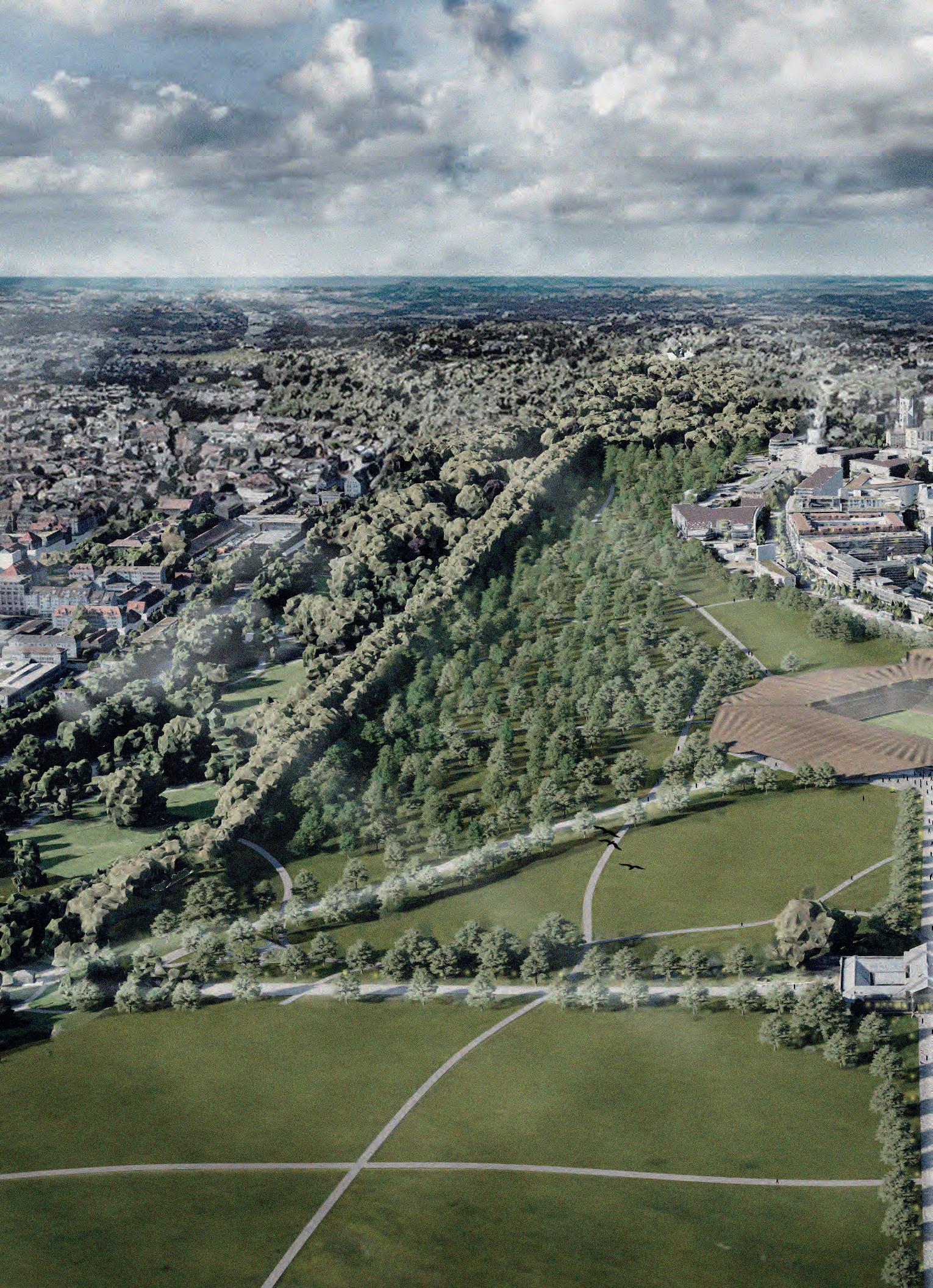
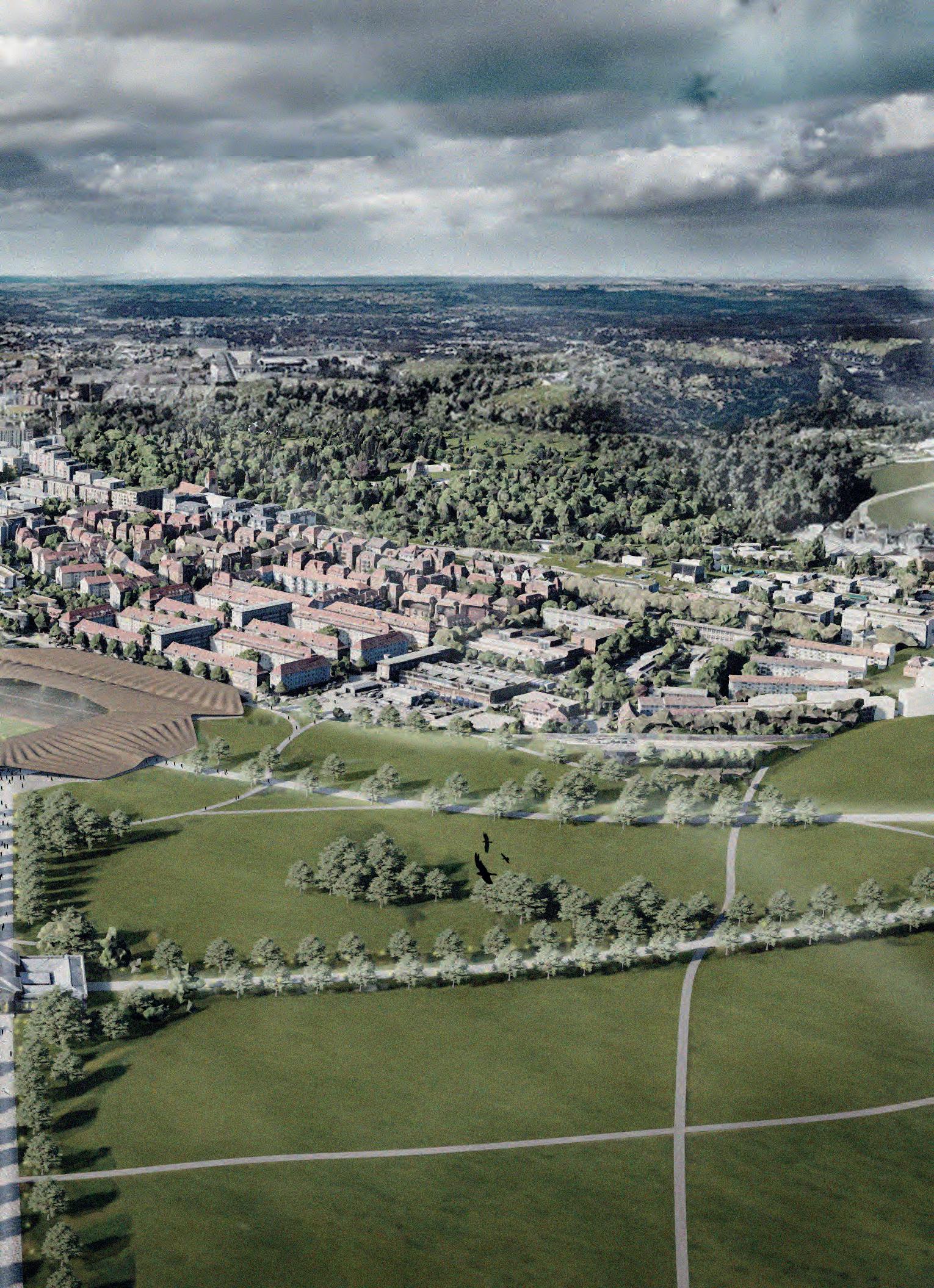
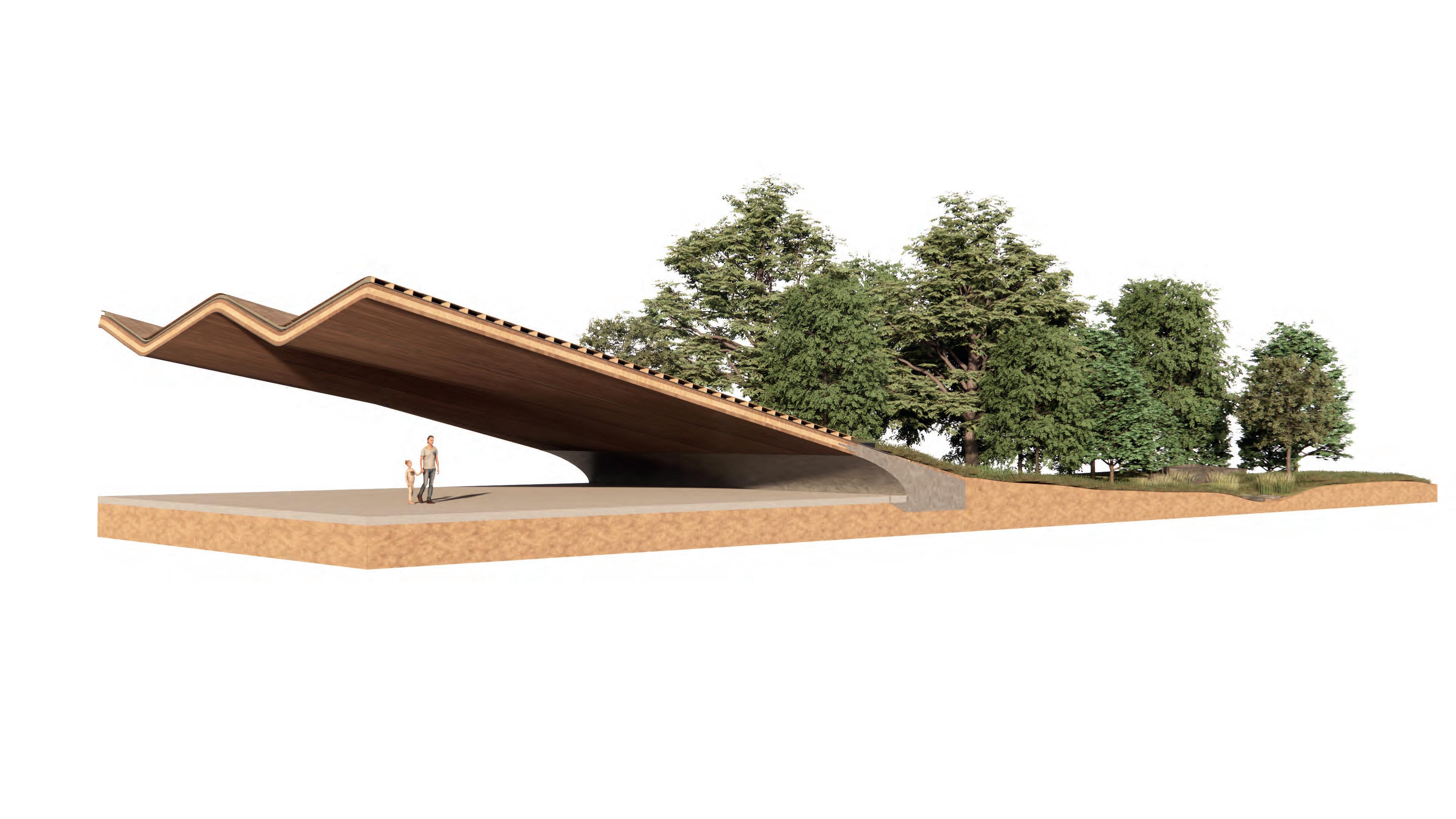
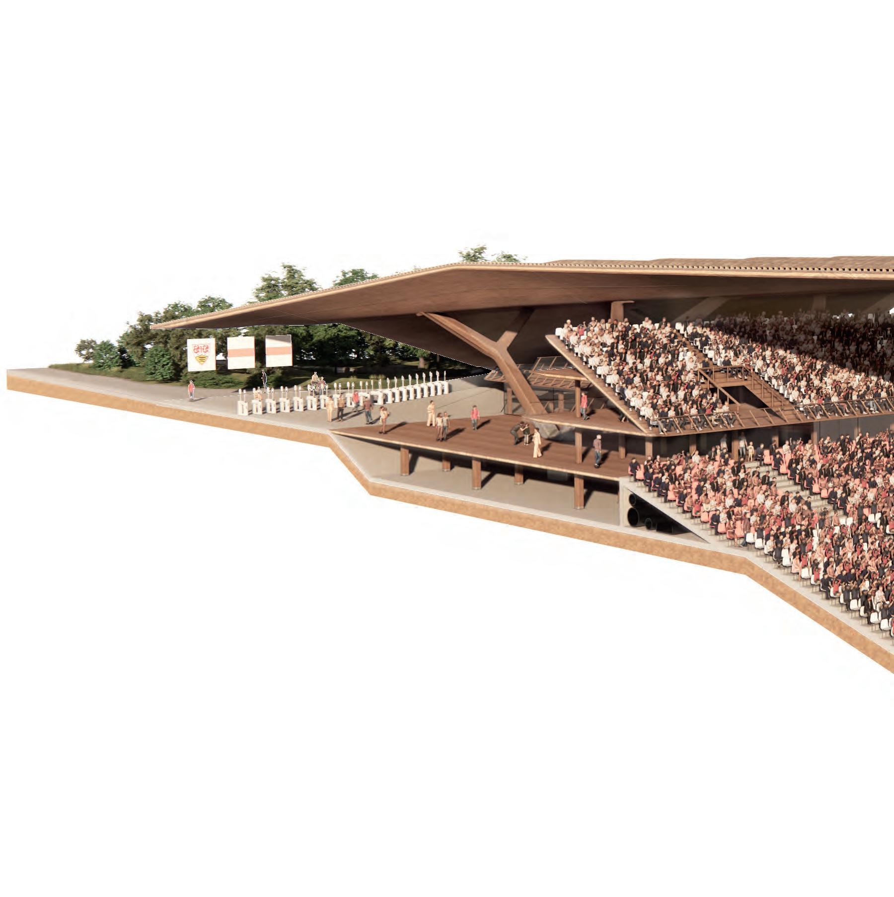
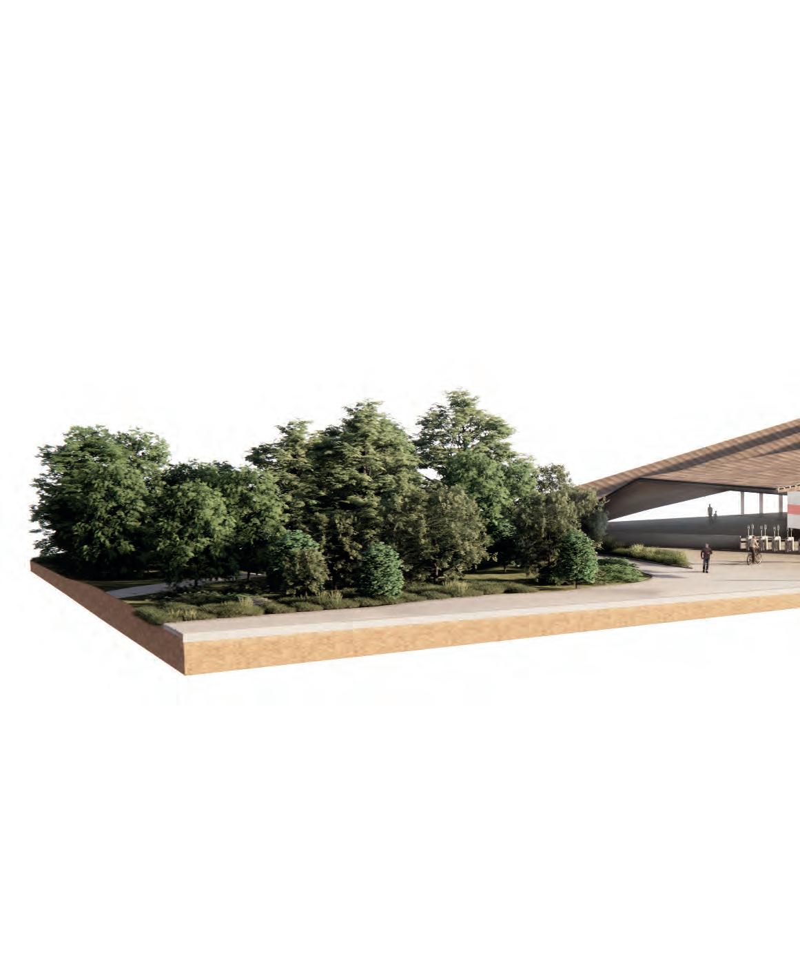
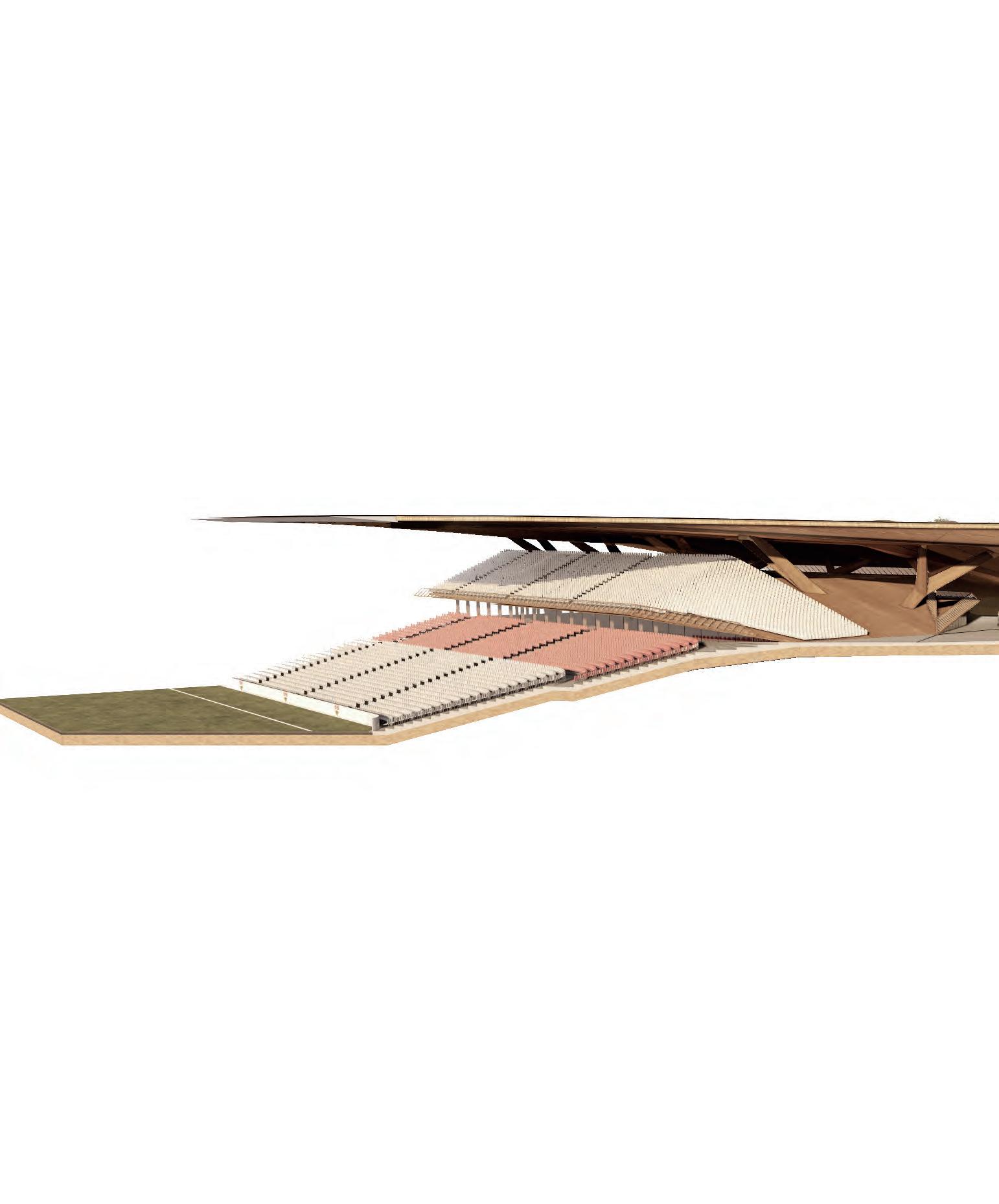
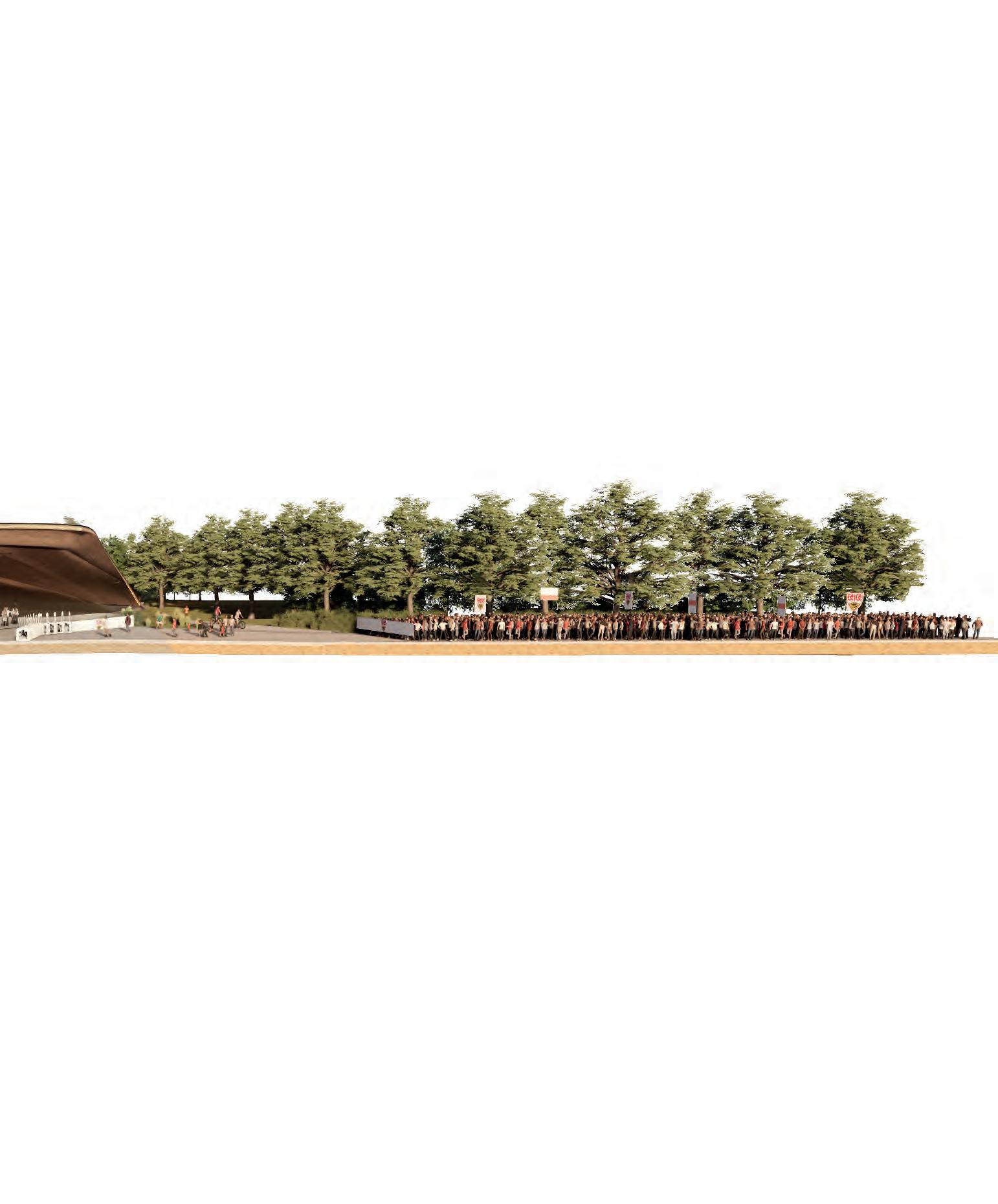
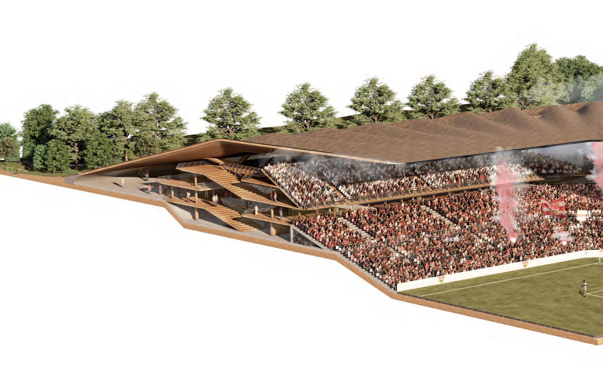
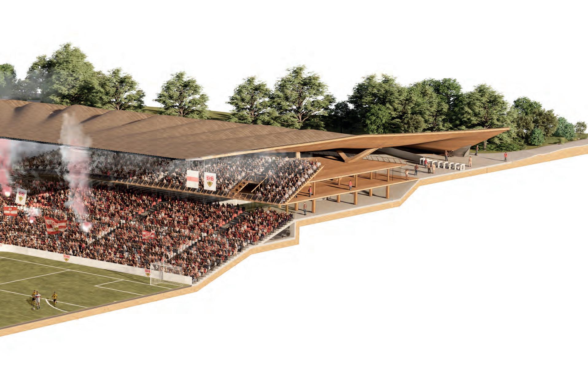
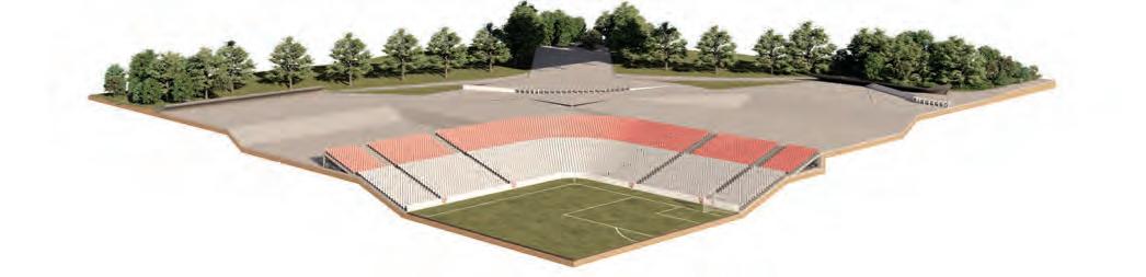
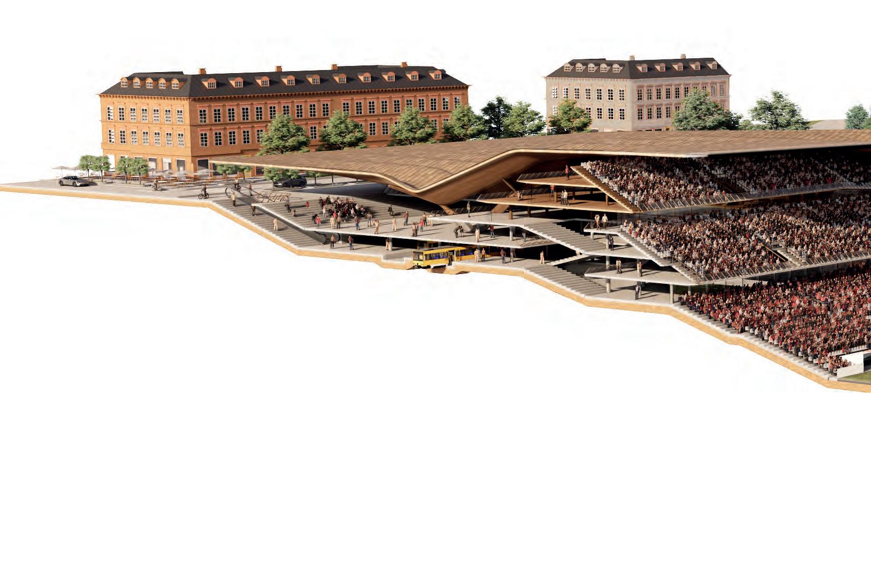
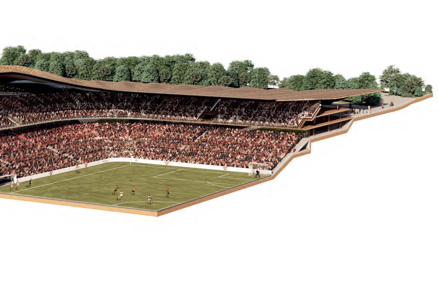
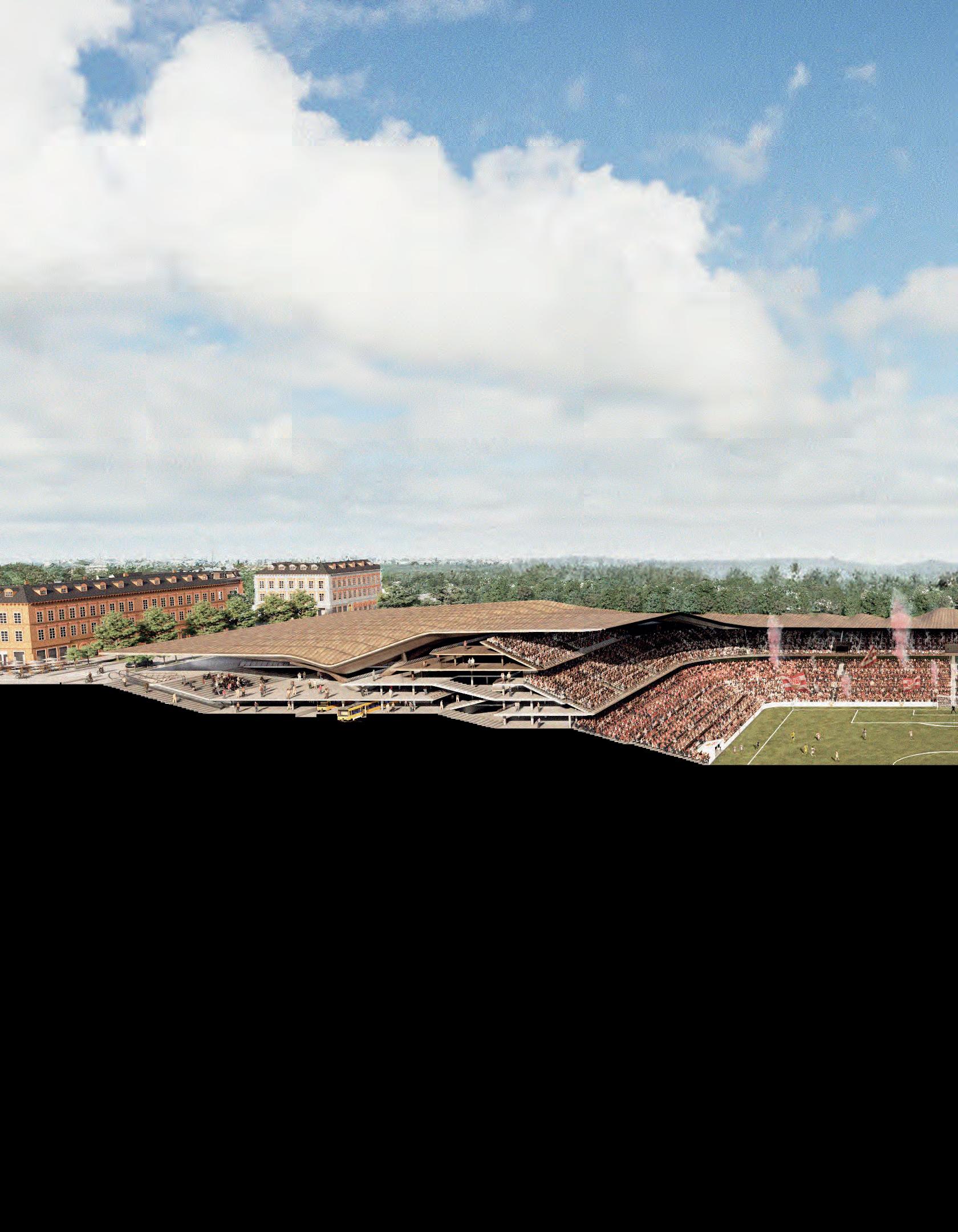
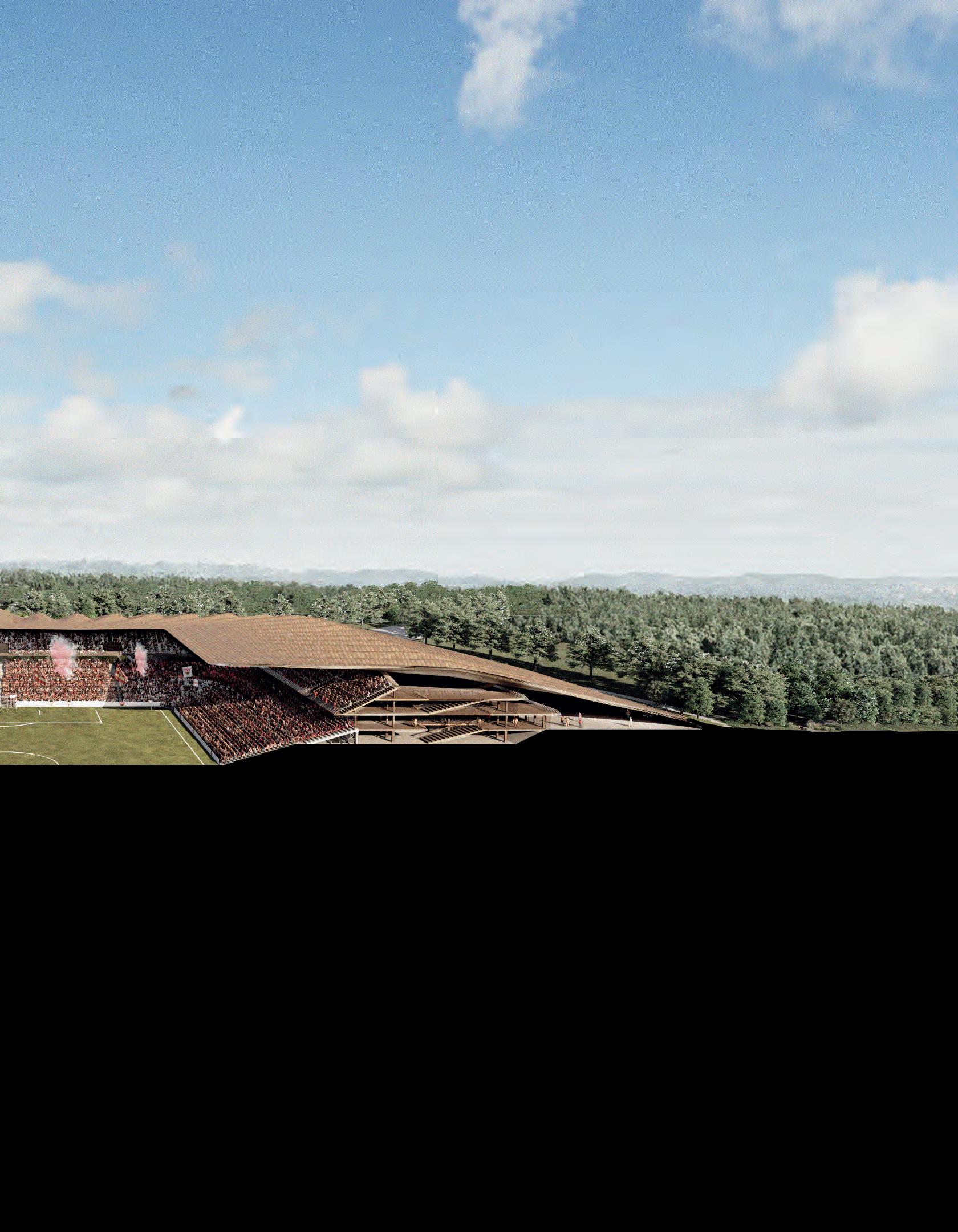
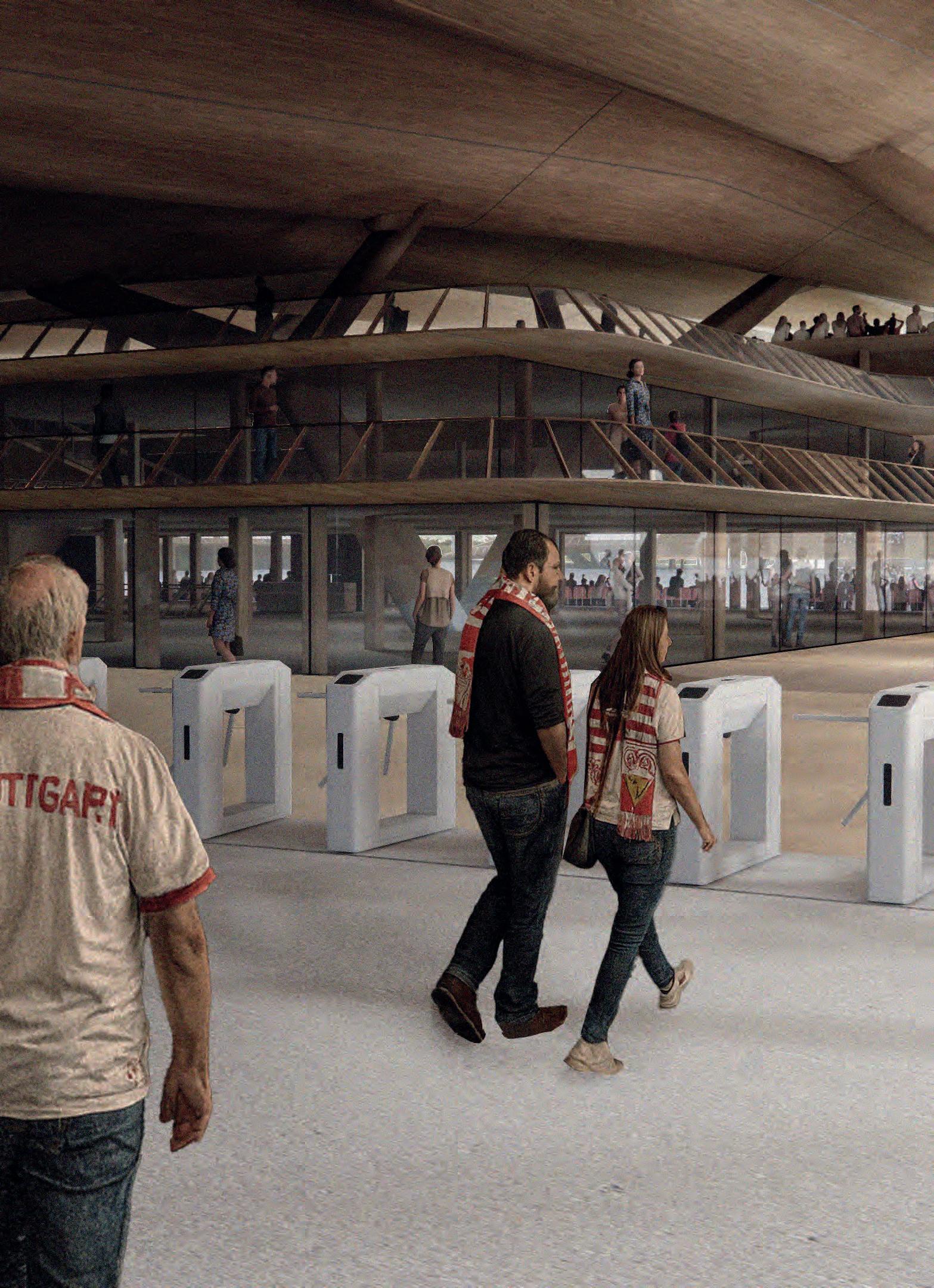
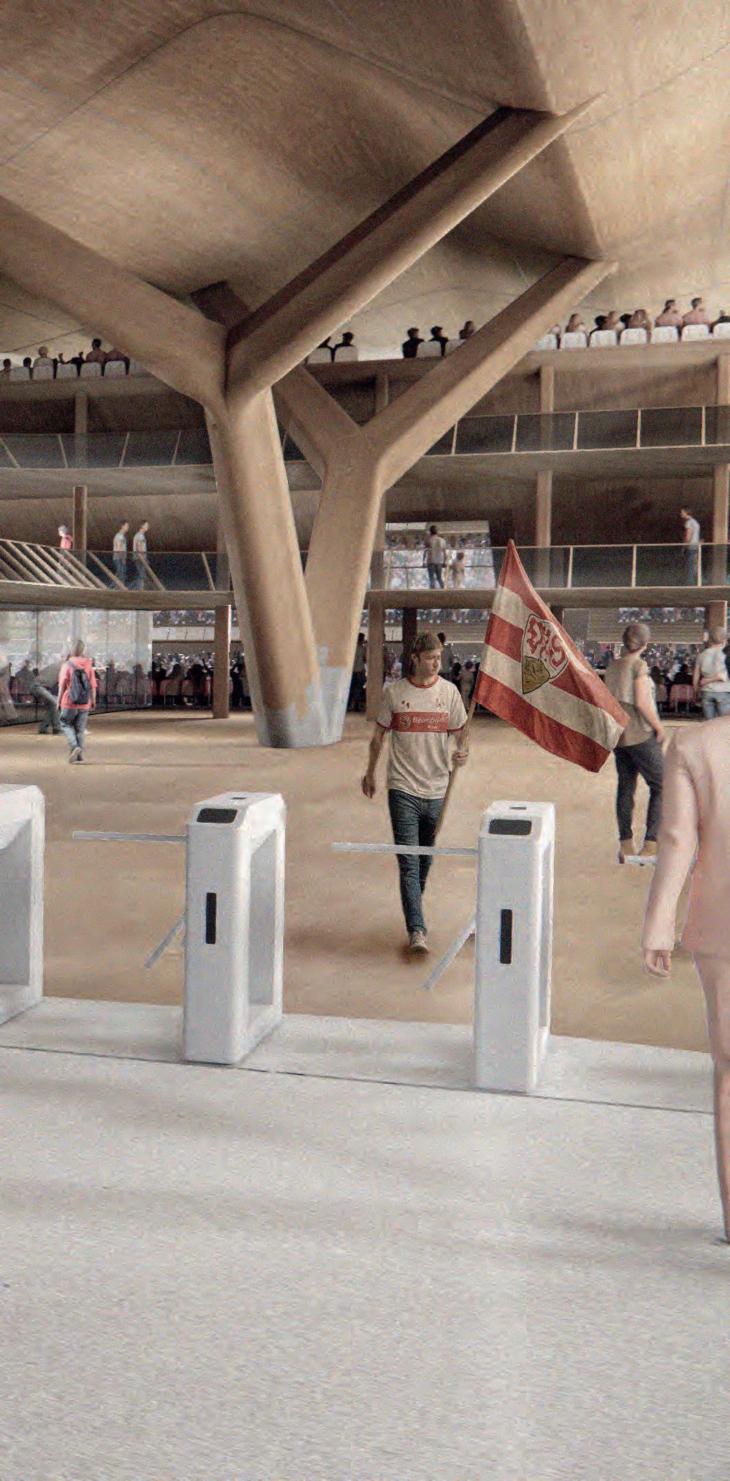
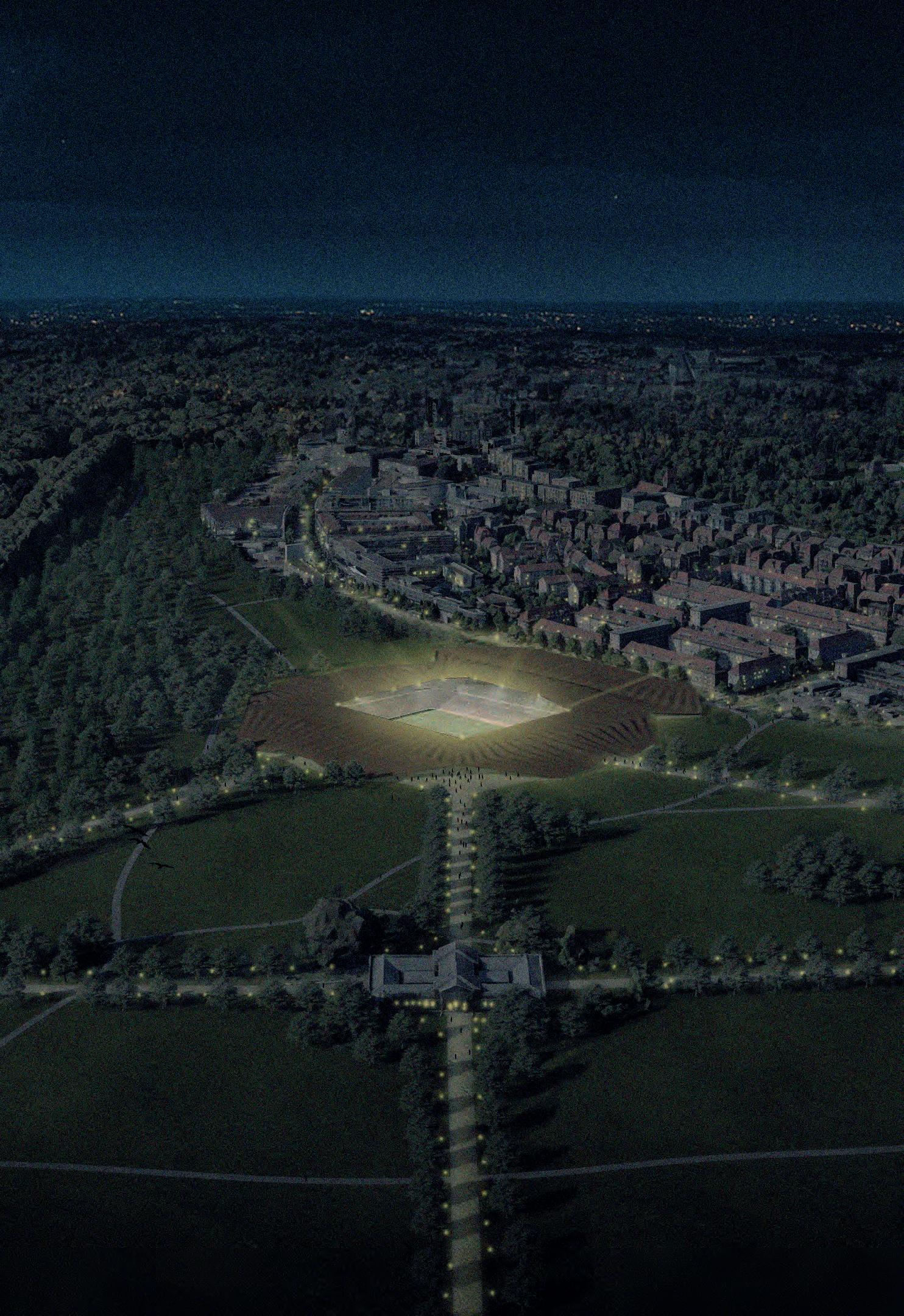
The project aims at creating a new stadium typology with a large-scale laminated timber roof. The design moves beyond the conventional notion of the stadium as a standalone arena, instead creating a building that is fully integrated into its social, environmental, and economic context. Located on the edge of a new park development near the city centre, the stadium embeds itself partly into the sloping landscape, opening toward the park while also maintaining strong connections to the surrounding urban fabric.
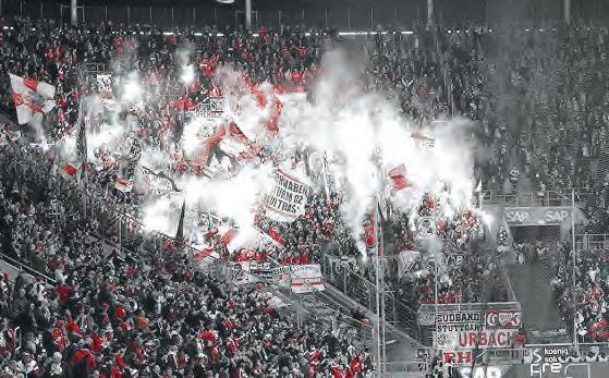
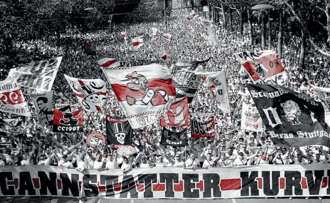
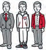
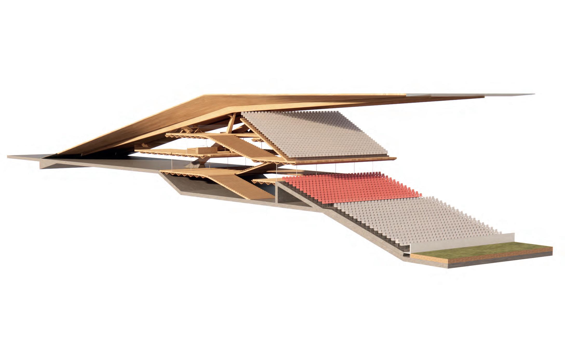
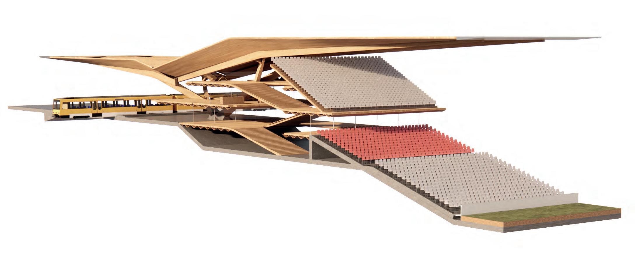
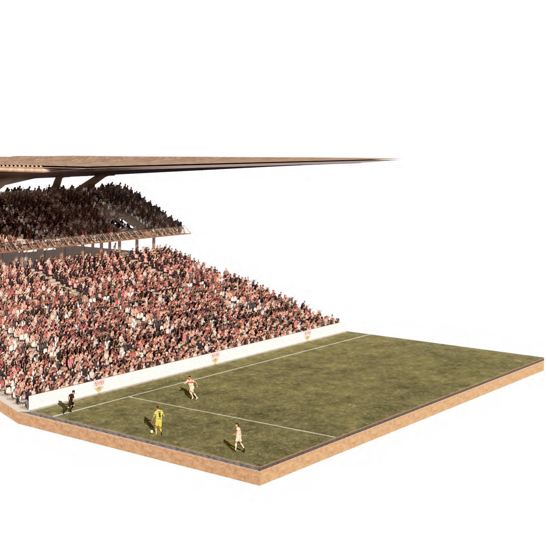
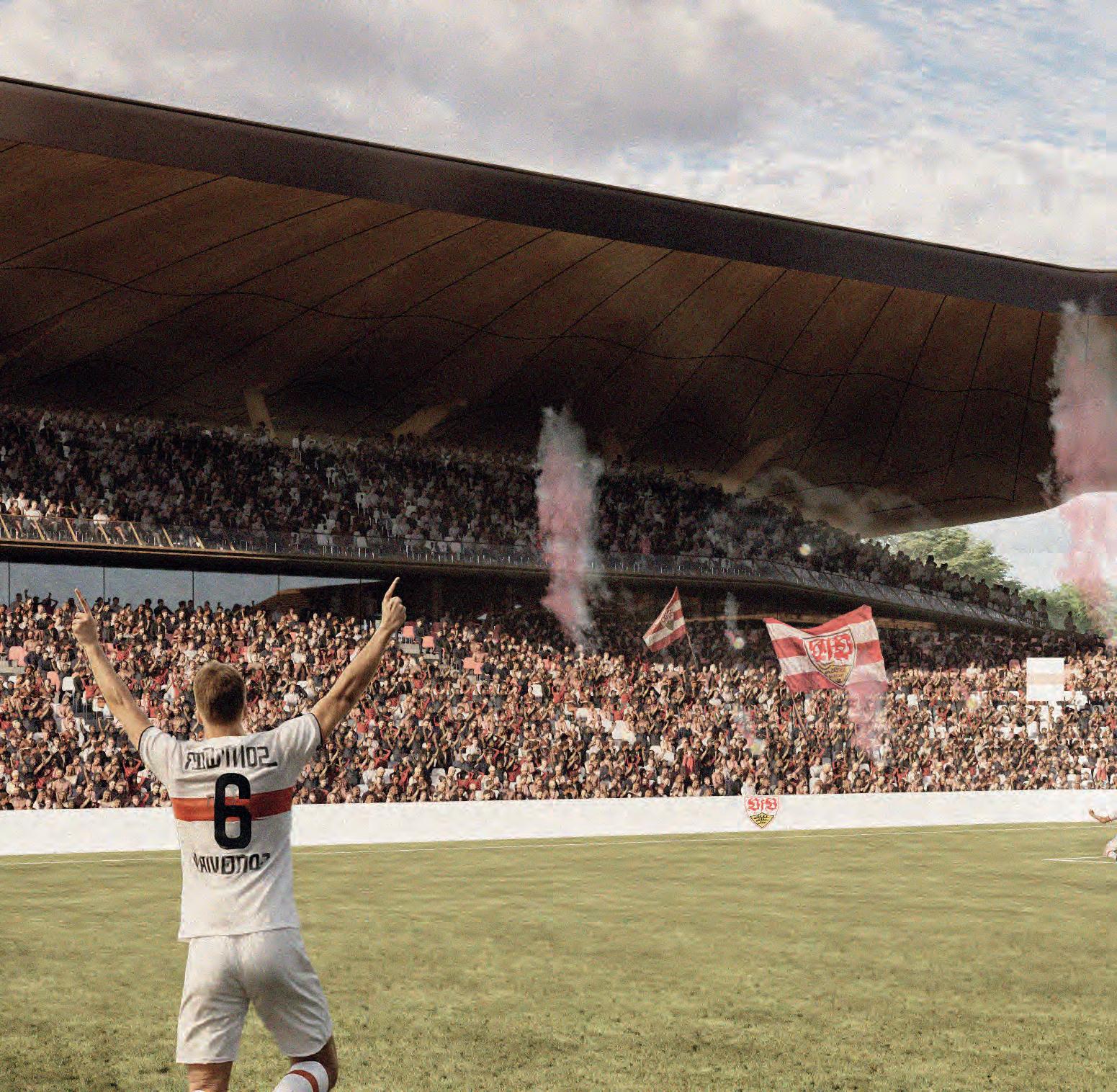
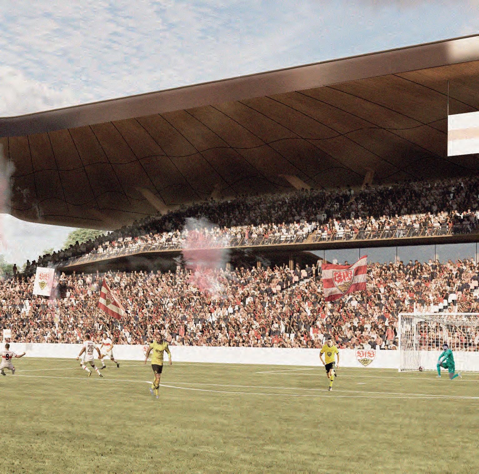
The design emphasizes inclusivity and fan culture, reflecting the unique traditions of German football. Supporter groups are carefully accommodated within the bowl, ensuring both integration and continuity while preserving unobstructed sightlines from every seat. Public spaces such as gathering zones, hospitality areas, and pubs within the concourses are designed to
enhance the matchday experience and remain accessible beyond game days, strengthening the stadium’s civic role.
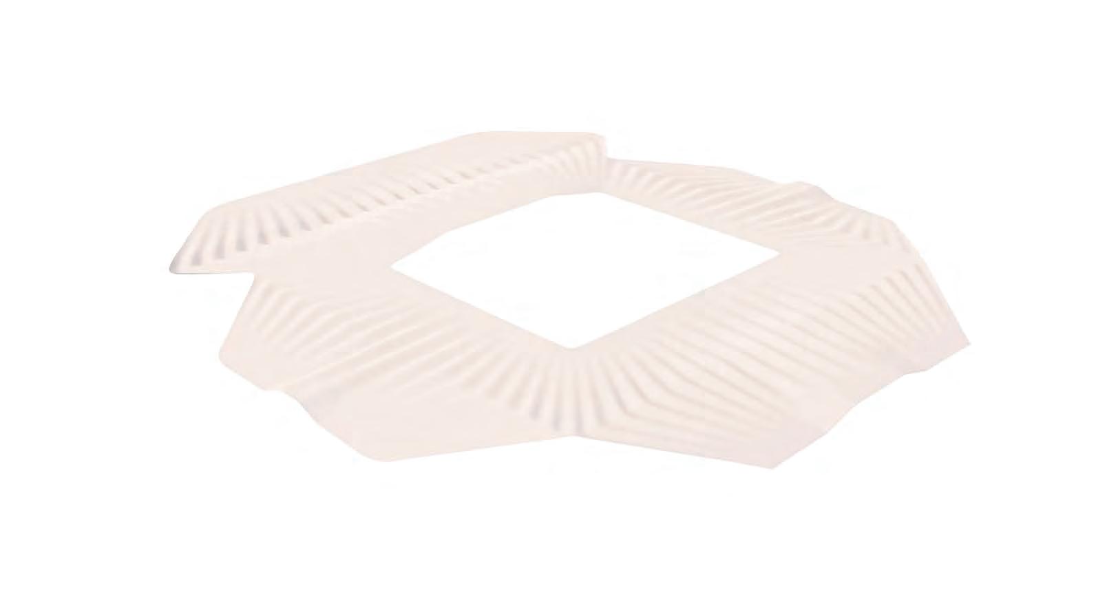
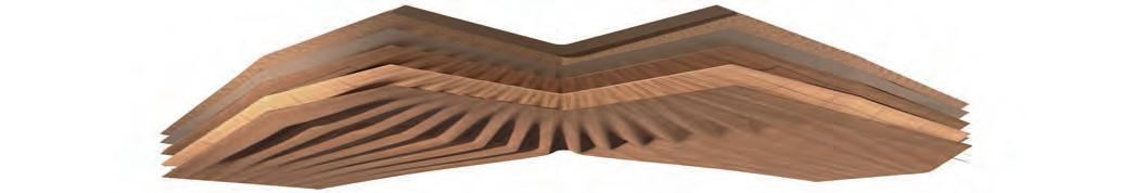
Structurally, the roof is designed as a continuous laminated timber surface optimized through bending, where curvature enhances stiffness and channels forces into axial tension and compression, minimizing material thickness while enabling an efficient and economical large-span structure.
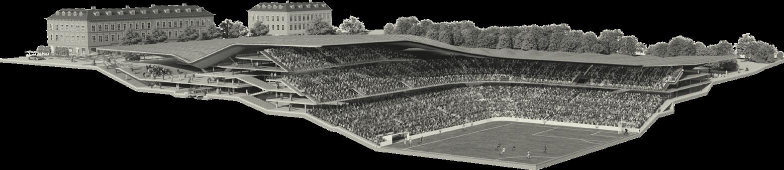
PHASE I
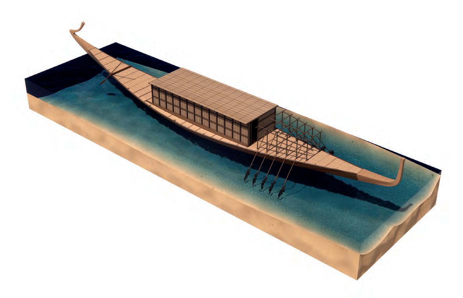
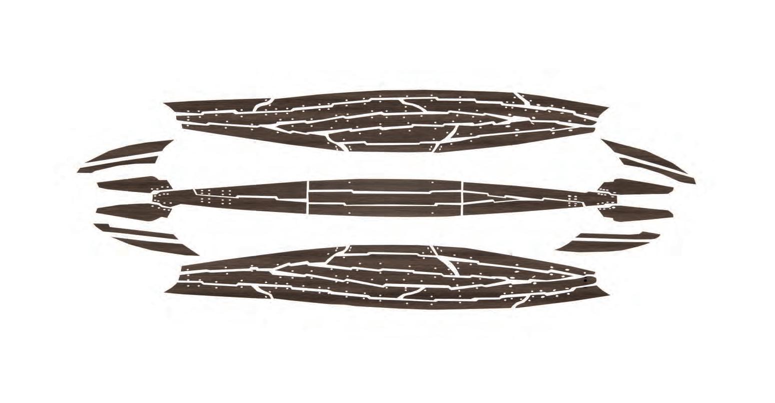
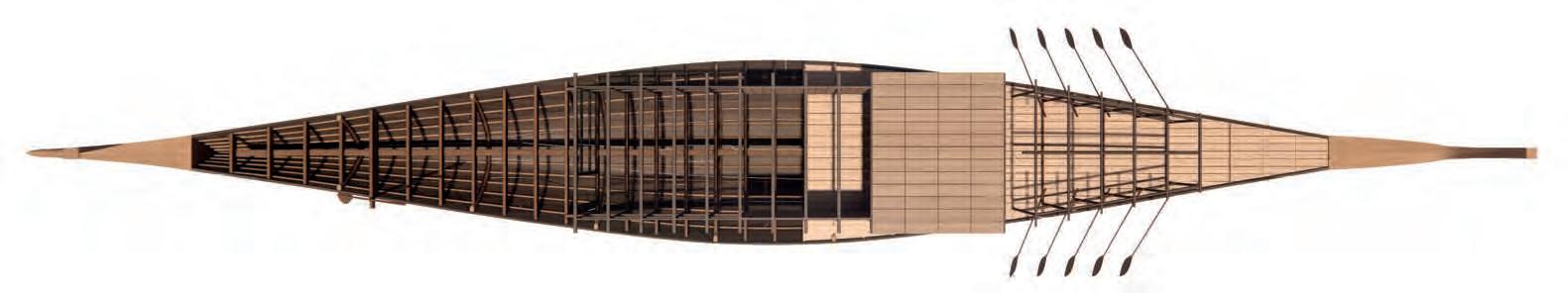
The Boat of Cheops was ancient Egyptian solar barque discovered near the Great Pyramid of Giza, believed to have been intended for Pharaoh Khufu’s journey across the heavens in the afterlife. Is is
frames
Known Boat
Hull Construction
Boat Components
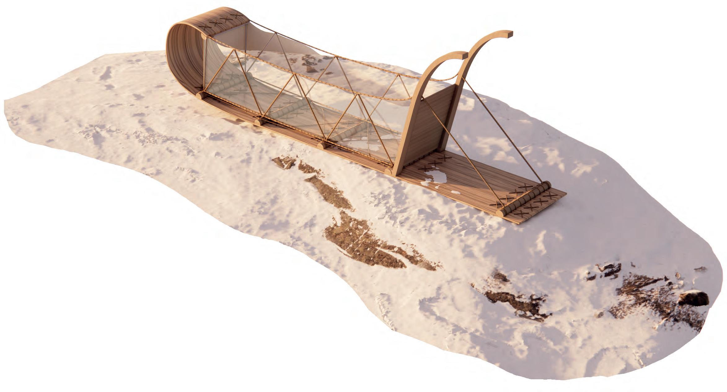
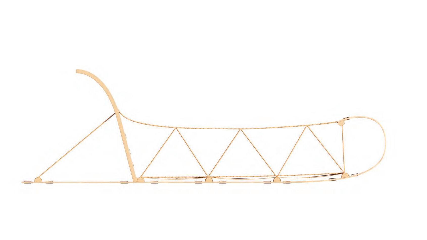
Transport Sled for the Innu
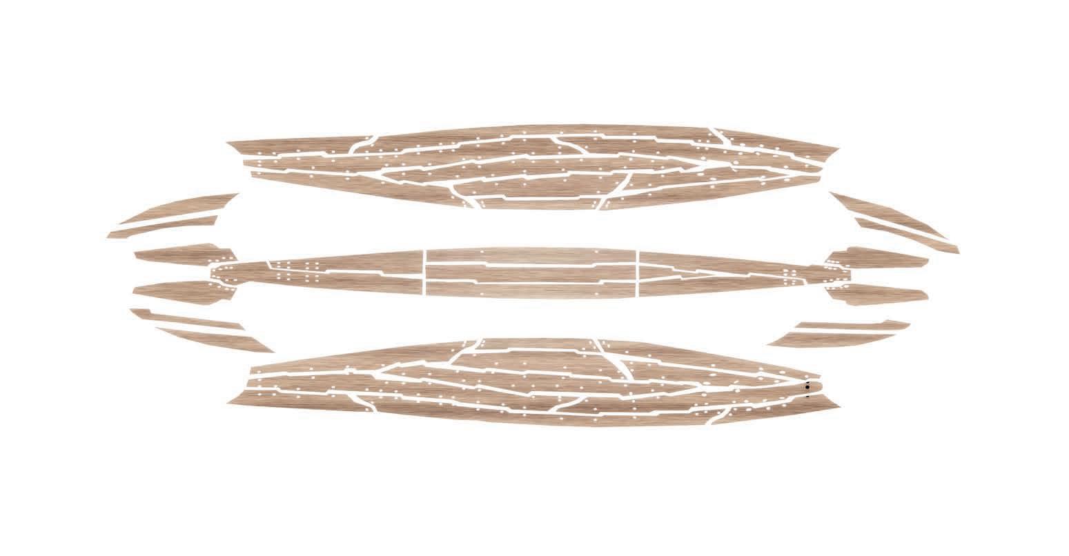
A narrower toboggan was used for general transport (goods but also children) in Innu culture (North-Eastern Canada). Thin hand-hewn birch planks are bent into form and sown/ tied together with rope. They are held together by transverse wooden bars. These are placed at the front of the portion, the second at the point where the curve begins, the third approximately in the center, and the fourth at the back
1890 Oldest Known Toboggan
Begin of Innu Displacement
Innu Sole Occupants of Labrador Coast (before Inuit Migration)
7500 BC First Innu Migration to North America to Quebec-Labrador Peninsula
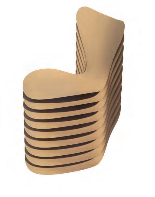
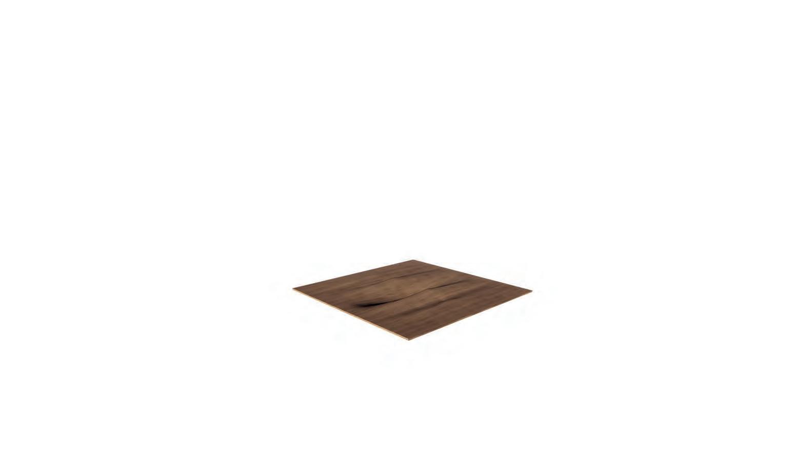
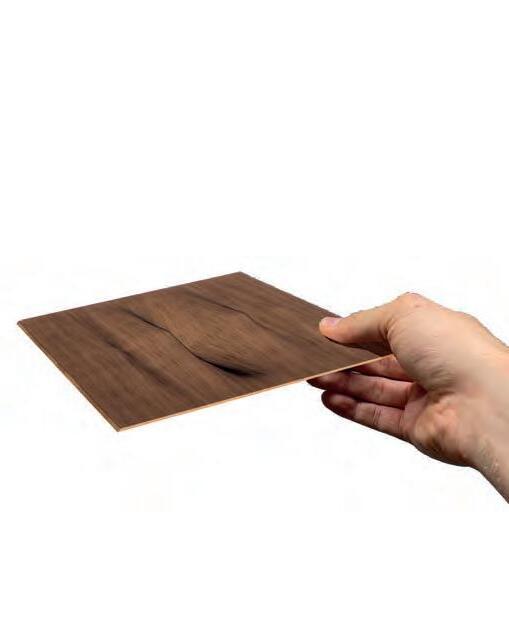
Stitched Veneers
Manufacturing of 9 stitched veneers
2 outer layers are oak, walnut, ash or maple
7 inner layers are beech
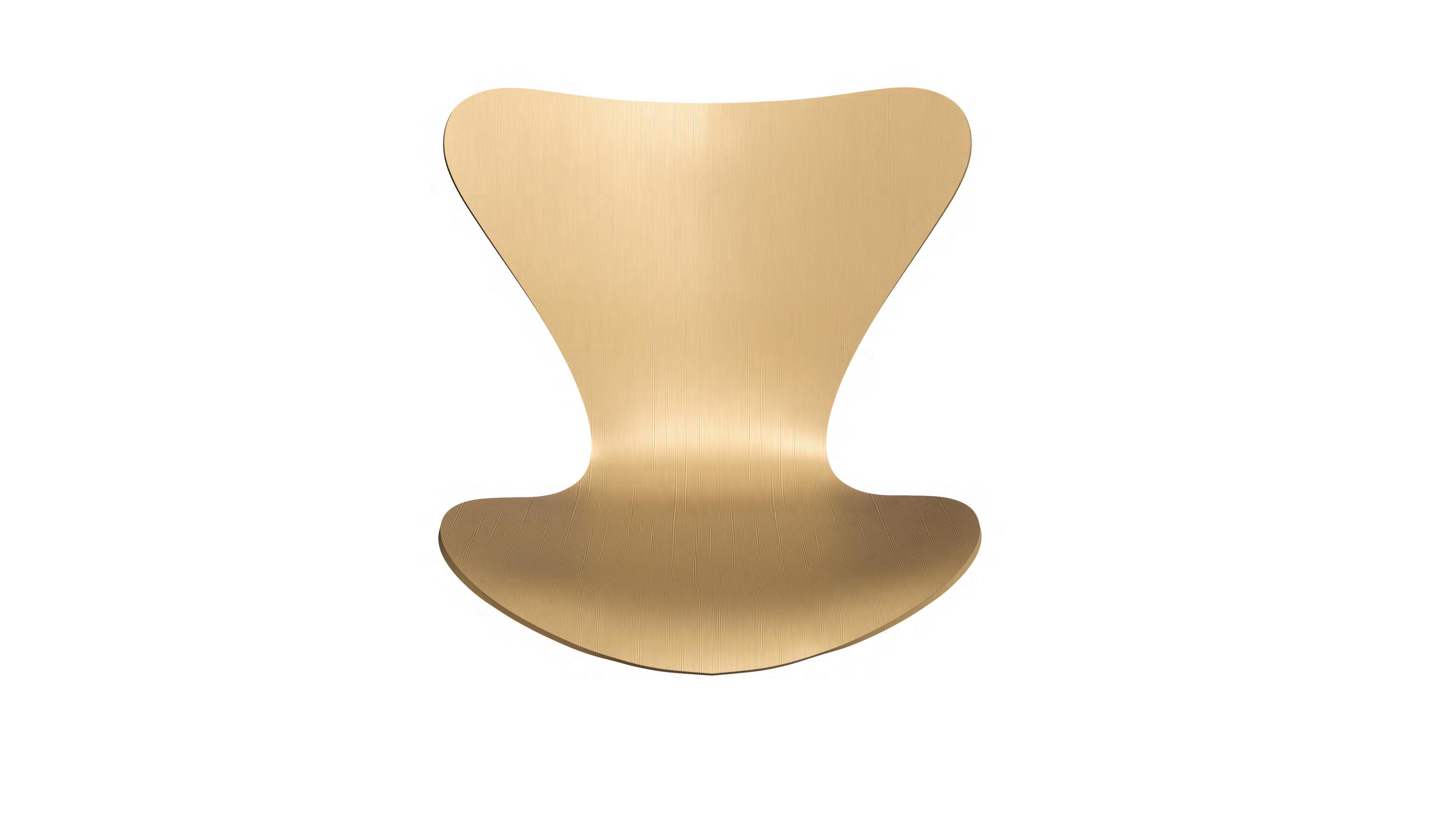
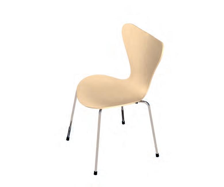
7 SERIES
ARNE JACOBSEN, 1955
Model 3107 Chair
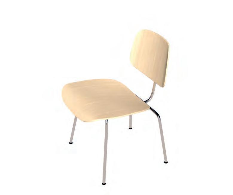
The chair, along with the Jacobsen’s Ant chair, was, according to Jacobsen, inspired by a chair made by the husband and wife design team of Charles and Ray Eames using their plywood bending techniques. It is one of the most commercially successful chair designs to date and is manufactured by Copenhagen based furniture brand Fritz Hansen.
Pressure Mould
9 Veneers are pressure moulded into shape Glued together with water-based urea-formaldehyde
Milled
Moulded and glued veneers are milled into final shape
Chairs are coated with polyurethane lacquer
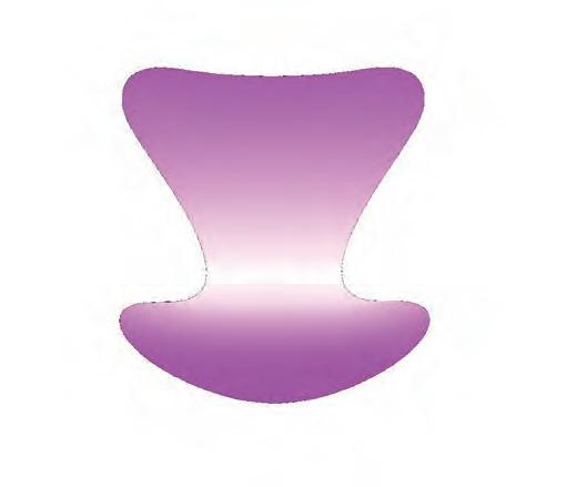
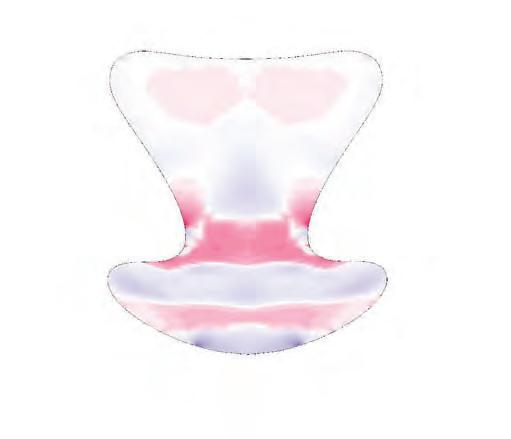
Deformation Utilization Principal Stresses
This deformation is run at a uniformly distributed load of 850 N/total area. The least amount of deformation occurs on the corner from seat to back rest.
7 SERIES
STRUCTURAL ANALYSIS
Structure and Force Lines
The moulded and glued veneers give the chair structural strength while also allowing for partial bending due to ductile properties of timber. This gives the chair shell high flexibility and it moulds into form when used. The diagram above shows force lines which represent the direction and strength of a force field.
The most utilization occurs on the corner from seat to back rest where the timber is under tension.
Theses stress lines show the maximum and minimum normal stresses acting at a particular point where shear stress is zero.
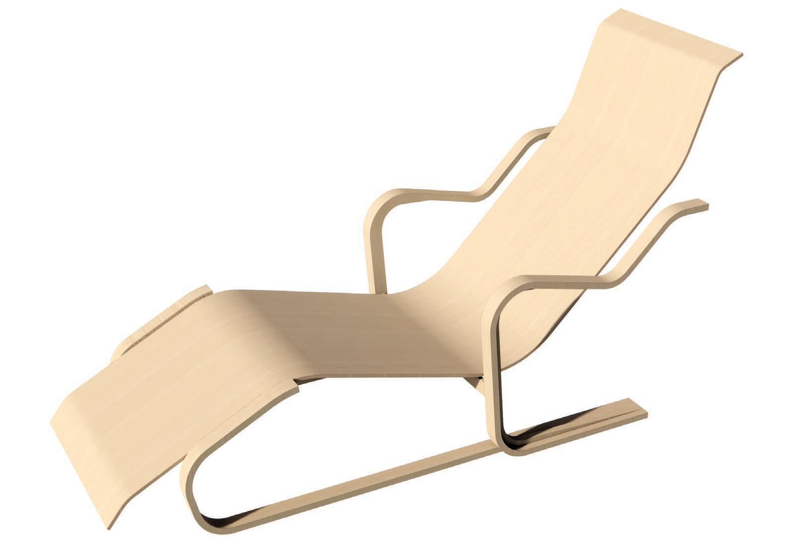
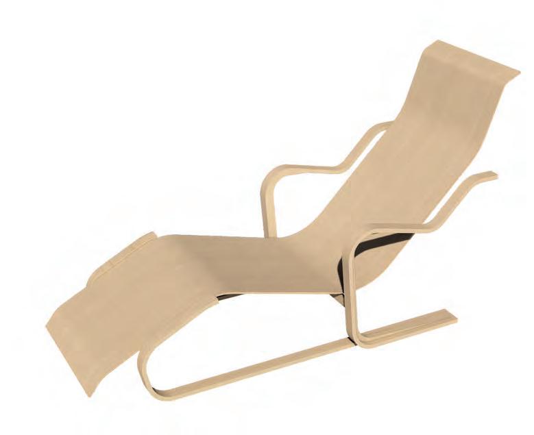
LONG CHAIR
The Long Chair by Marcel Breuer is one of the first examples of a laminated mould pressed plywood lounge chair. It uses birch ply for the seat and the laminated frame.
MARCEL BREUER, 1936
Isokon Furniture Chair
BODY LITTER
RAY & CHARLES EAMES, 1943
War Time Prototypes
Designed between 1942 and 1945, the Eames Wartime Prototypes were a series of designs for use in WWII. A full body litter (stretcher) was developed using the very strong Plyform material, made from layers of molded plywood fused together using heat and glue. The litter had been molded to the contours of the human body along with multiple slots on its circumference in order to attach ties or act as carry handles.
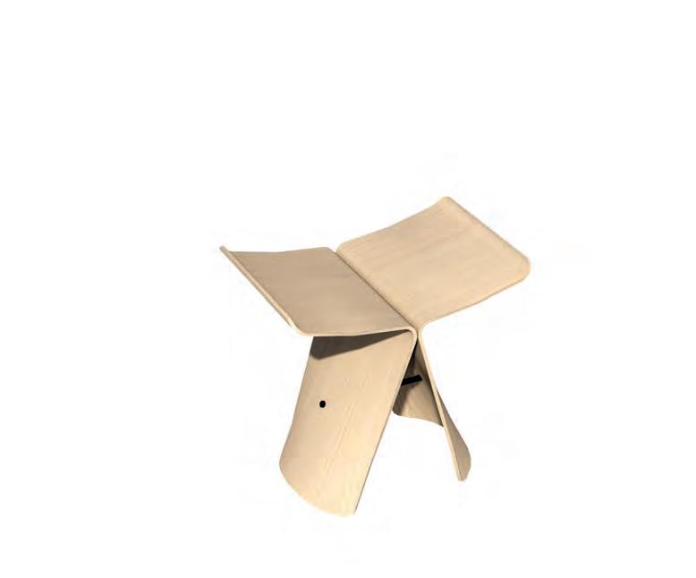
PLYWOOD FURNITURE
POSTWAR INNOVATION
Eames to Jacobsen
The wartime innovations proved that wood could be engineered for performance and aesthetics—leading to a boom in its use in postwar design. It inspired many designers and architects to explore new ways of bending wood and using thin veneers to create surface driven furniture design.
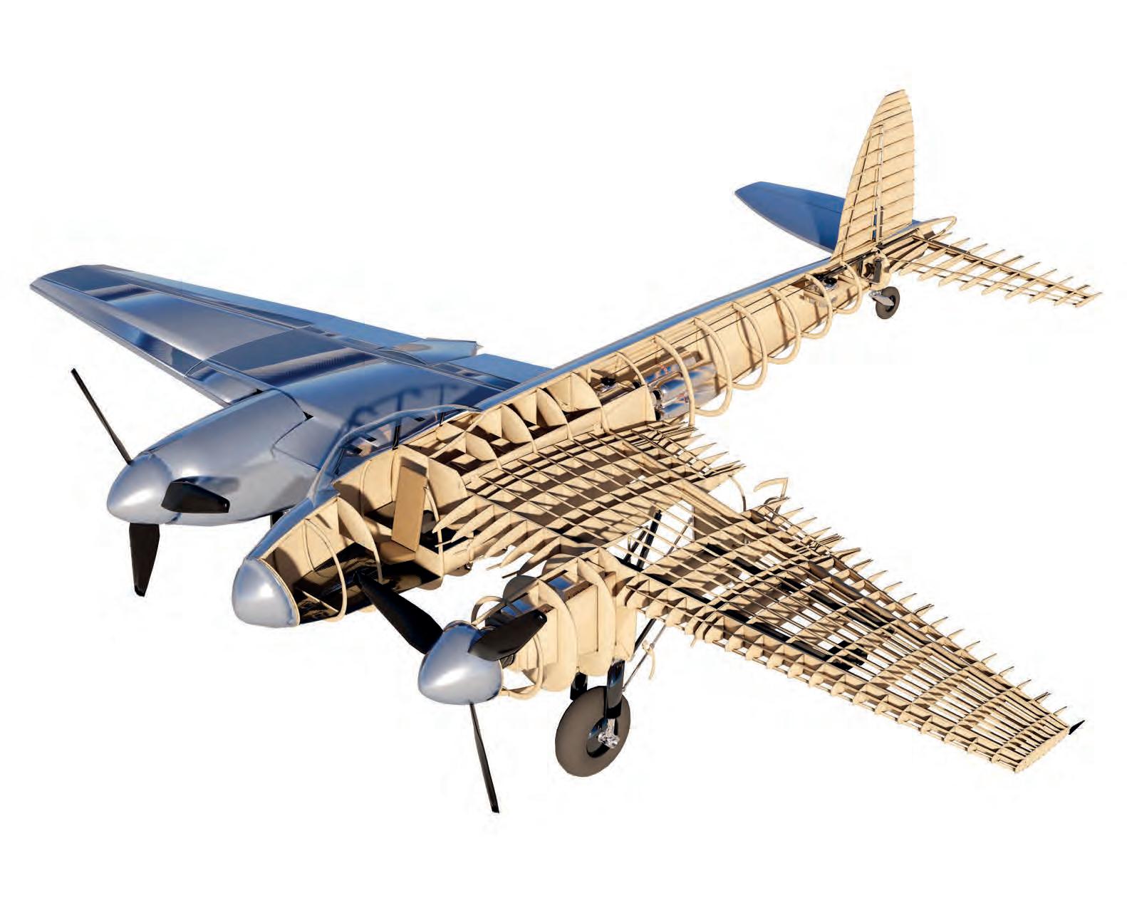
MOSQUITO AIRPLANE WOODEN WONDER
The de Havilland Mosquito uses thin birch and balsa veneers for it’s monocoque fuselage. The design of the fuselage uses two molded halves made from layers of birch plywood (3 mm) sandwiching a balsa wood core (9mm). These halves were constructed in separate molds, bonded with casein or later synthetic adhesives, and then joined together to form a strong, lightweight shell
Laminated Monocoque
Balsa Wood Steel Cabling Inner Skin
Multi-Ply
Plywood Strips
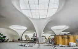
URBACH TOWER
LAMINATED TIMBER TOWER
Large Scale Surface Timber Construction
he Urbach Tower, designed by ICD/ITKE at the University of Stuttgart is a rare example of large scale curved surface driven timber construction using digital manufacturing methods (Fig. 1.37.). Twelve unique panels were engineered using high-moisture, bi-layer spruce CLT that deforms into precise curves during standard kiln-drying, fully programmed by wood’s natural hygroscopic properties.
Flashing Plate
Facade Layer, Larch 20 mm
Facade Counter-Battens, Spruce 27 mm
Battens, Spruce 2 x 25 mm
CONSTRUCTION
JOINARY AND LAMINATION
From Panel to Tower
Panels (5 m × 1.2 m) are overlapped, glued, and CNC-milled to exact dimension, forming larger curved structural components up to 14 m tall and only 90 mm thick. The span-tothickness ratio achieved is 160:1.Prefabricated in four groups (three panels each), the tower was assembled in a single day The structure is finished with a polycarbonate roof and larch cladding for weather protection.
Facade
Membrane
Load Condition (Point Load)
Load Condition (Uniformly Distributed Load)
Diagram
Moment Diagram
Multi-Support Point Loads
STRUCTURAL BENDING
GEOMETRIC STIFFENING Structure Through Folds
Under a uniformly distributed load (UDL) or a point load, a two sided pinned beam experiences tension on the underside and compression on the topside. For this reason, wood beams are often made with the strongest grain orientation longitudinally with most material or the strongest laminates concentrated furthest from the neutral axis, optimizing the section’s moment of inertia.
Shear Diagram
Diagram
UDL (Uniformly Distributed Load)
Gable
Parabolic Arch
Shear
Loads & Deformation
& Vertical Deformation
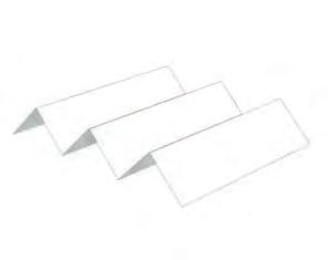
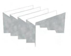
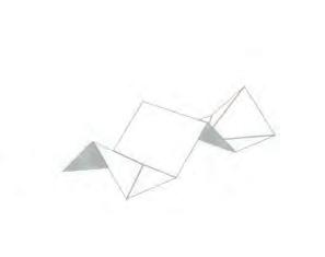
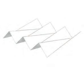
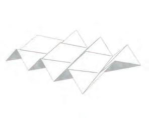
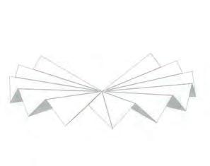
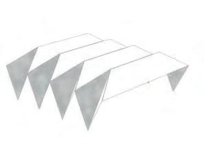
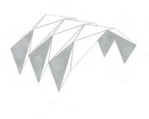
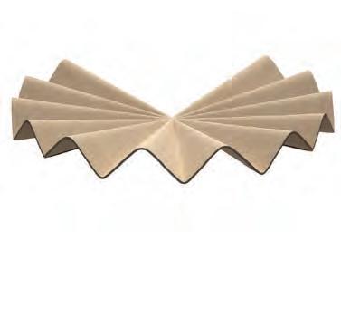
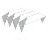
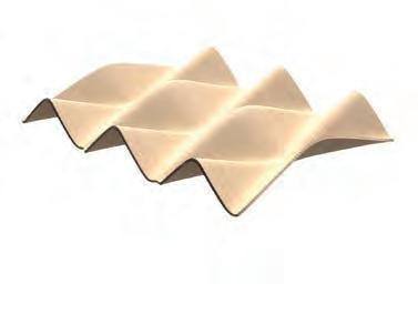
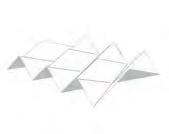
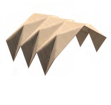
FOLDS
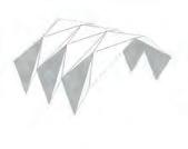
TAXONOMY OF FOLDING Structure Through Folds
Loads & Deformation
The idea of theses tests is to see how folding can be used to create timbers surface structures. Folds can be simulated with papers and to a certain degree replecated with wood. The taxonomy shows all types of folds from simple folds to more 3 dimensional spatial folds.
One-Sided Fold
Horizontal Deformation
Horizontal Fold
Vertical Fold
Buckling
Facated Wall Truss
Simple Folds Spot or Facet Folds
Frame Folds Spatial Folds
Facetted Fold
Two Hinged Frame Fold Three Hinged Frame Fold Dome Fold Pyramidal Fold
Continuous Frame Fold
Mirrored Fold
Two-Sided Fold Radial Fold
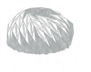
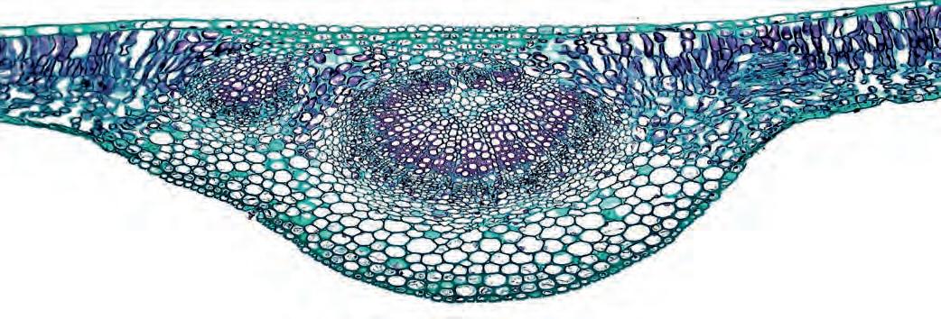
LEAF STRUCTURES
VEINS & NODES
Structure Through Folds & Branching
Leaves create structural stability through a network of veins that distribute mechanical stress evenly. The primary vein (midrib) provides central support, while secondary and tertiary veins branch out to form a strong, flexible network. This vein structure allows the leaf to withstand forces like wind and rain without damage.
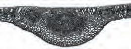
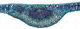
Xylem
Phloem
Stoma
- Leaf Vein Section
Leaf Vein Detail
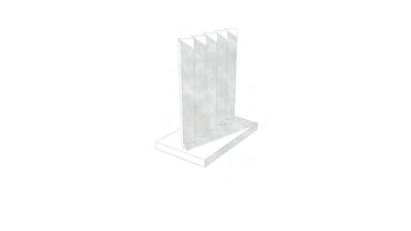
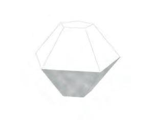
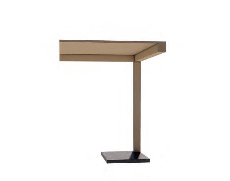
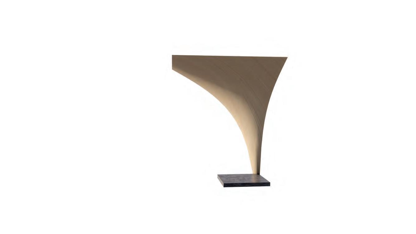
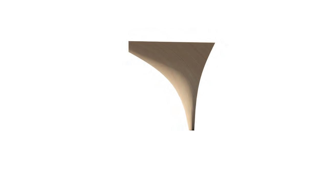
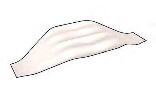
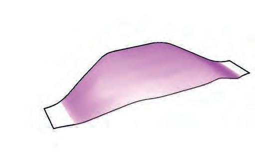
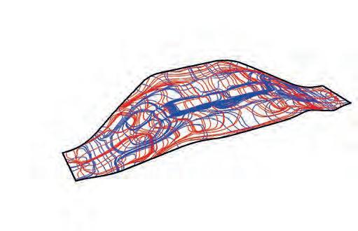
The aim of this prototype is to reduce the amount of material and create a surface based structural system. A column is replaced by a stretched optimized geometry which is then stress analysed. Principal stress lines are derived which create optimal paths for curving the wood. Theses ‘channels’ increase inertia and stabilize the structure.
Simple Column Beam Connection Assembly
COLUMN INTEGRATION
PROTOTYPE
Scaled Digital Model
The aim of this prototype is to reduce the amount of material and create a surface based structural system. A column is replaced by a stretched optimized geometry which is then stress analysed. Principal stress lines are derived which create optimal paths for curving the wood. Theses ‘channels’ increase inertia and stabilize the structure.
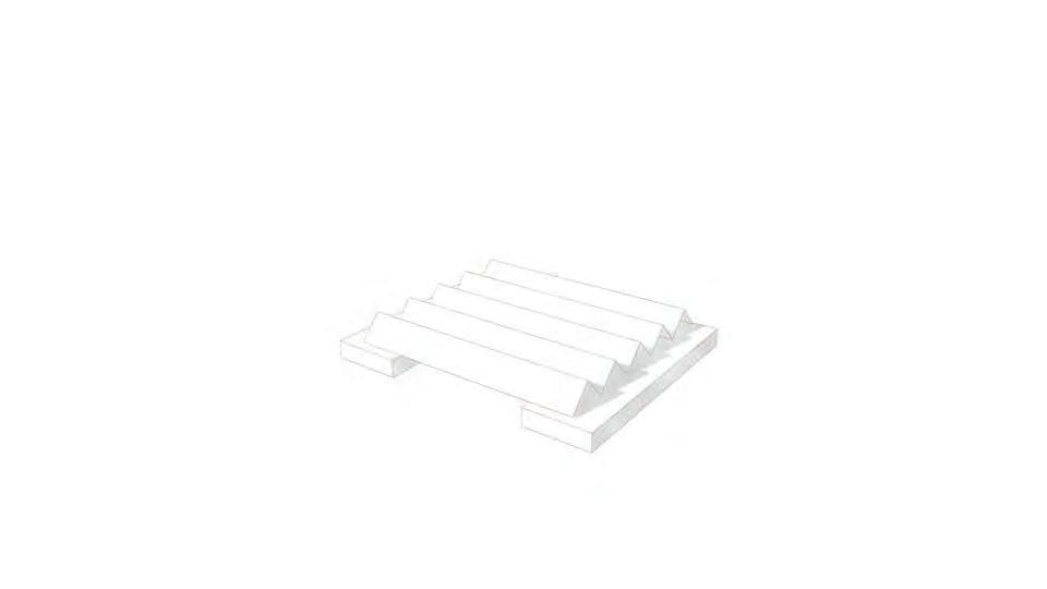
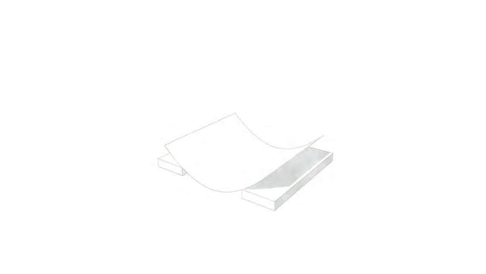
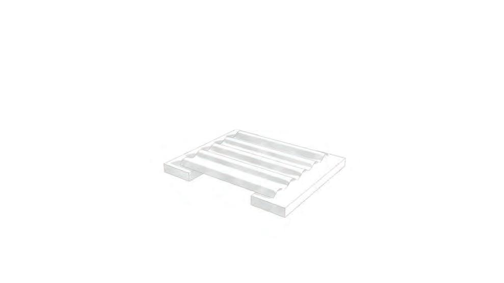
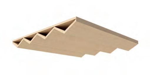
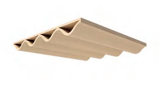
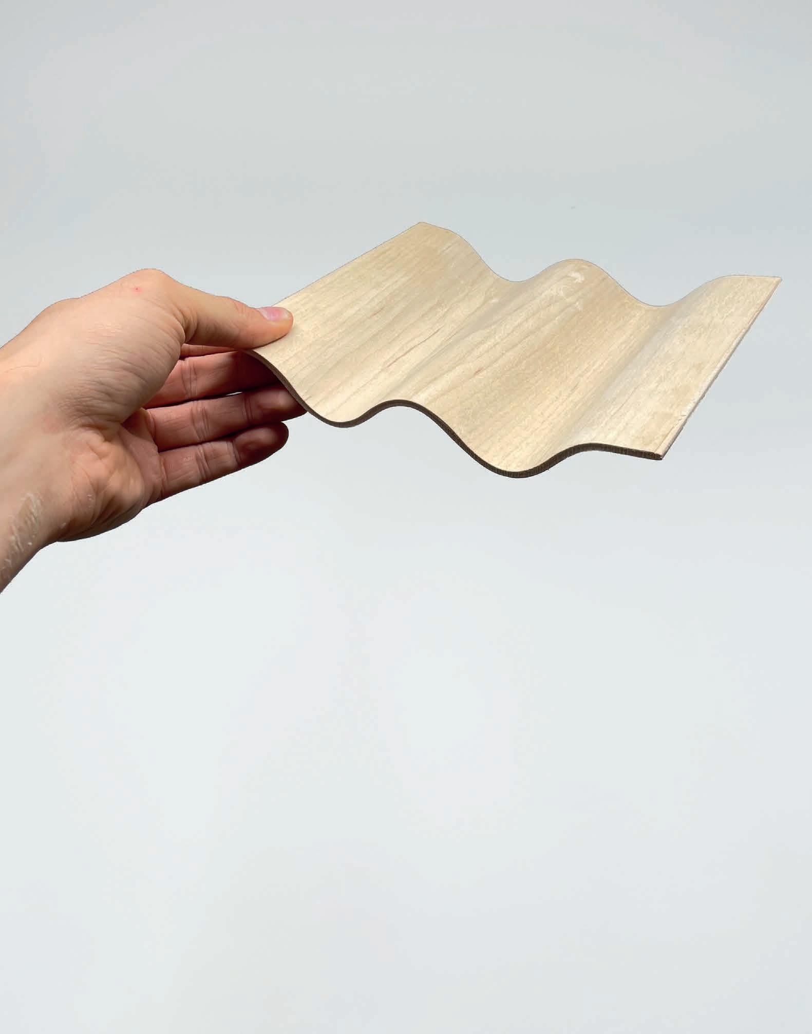
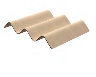
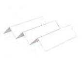
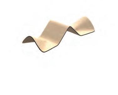
CORRUGATED WOOD PHYSICAL MODEL
Strength Through Bending
Corrugation is used to strengthen the load capacity of walls and floors. The rippled surface gives the cross section higher inertia against changes in rotational motion. This technology can be applied with reinforced concrete metal decking but has not been thoroughly tested with timber members.
Geometry
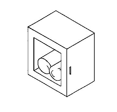
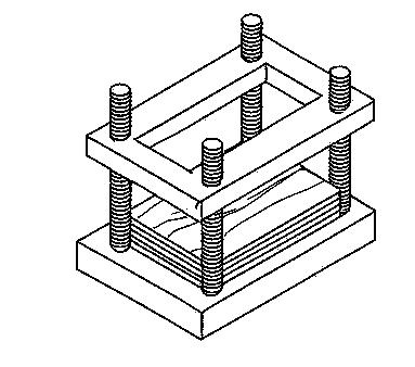
MOLD PRESSING
PHYSICAL TESTING
Geometry, Press & Time
Single pieces pf mould pressed timber can only achieve single curvature (whereas double curvature is only possible with cuts or additive techniques). For good results it is crucial to apply equal pressure to the male and female mould. Finally, press duration and moisture of the timber pieces affect the quality of mould and how well it stays in form.
Pressing
Physical Model
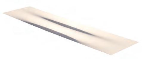
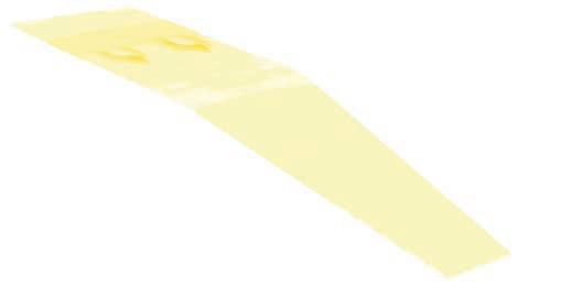
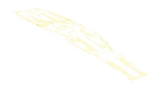
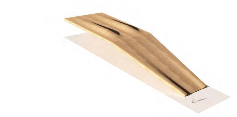
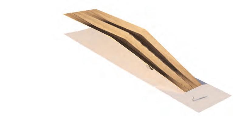
FOLD ITERATIONS
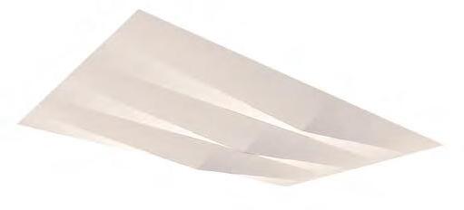
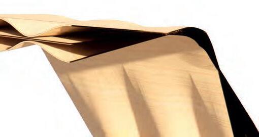
WOOD SURFACE BENDING
Folds
These are timber representations of ‘impossible’ timber folds. Impossible, because the folding angle is very high and would require incredible thin veneers. Breaking the components into smaller pieces would enable more geometric flexibility and help avoid the issue of impossible folds.
Impossible
Enclosure
Impossible Folds
Stairs
Levels
Bridge
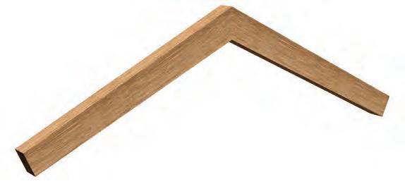
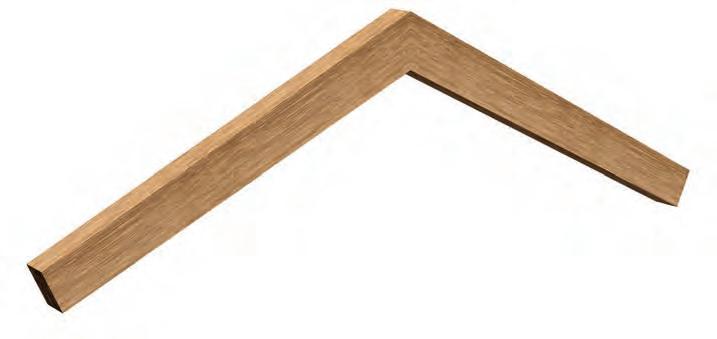
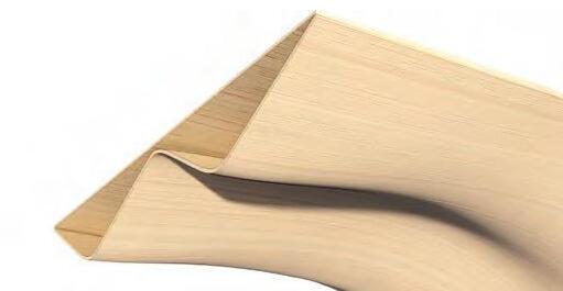
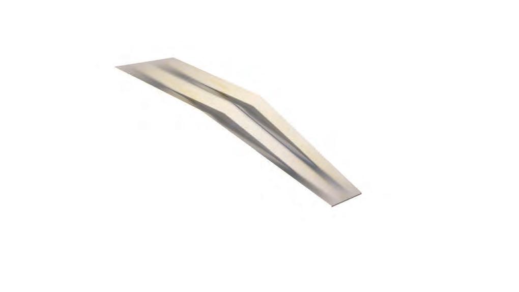
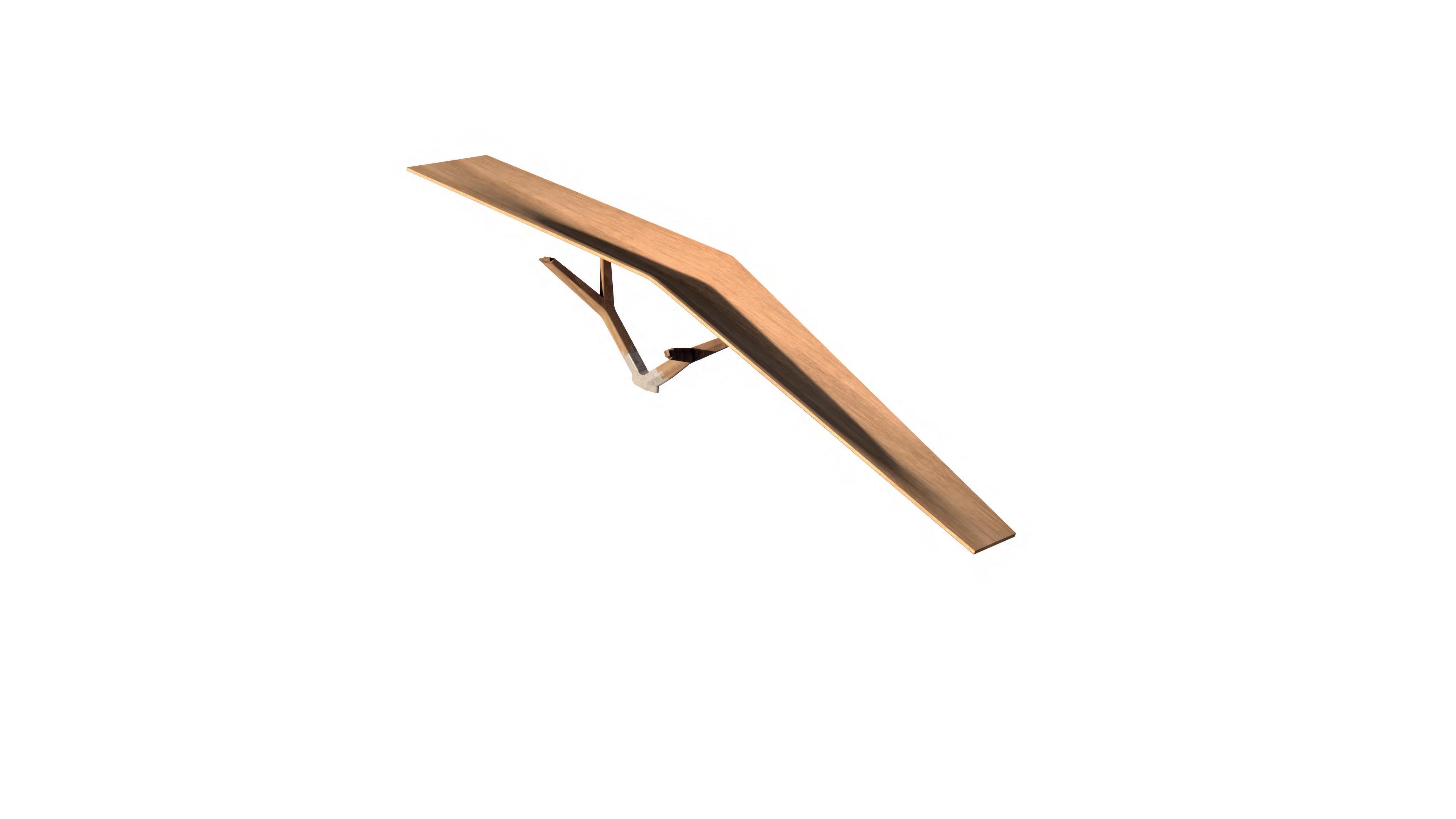
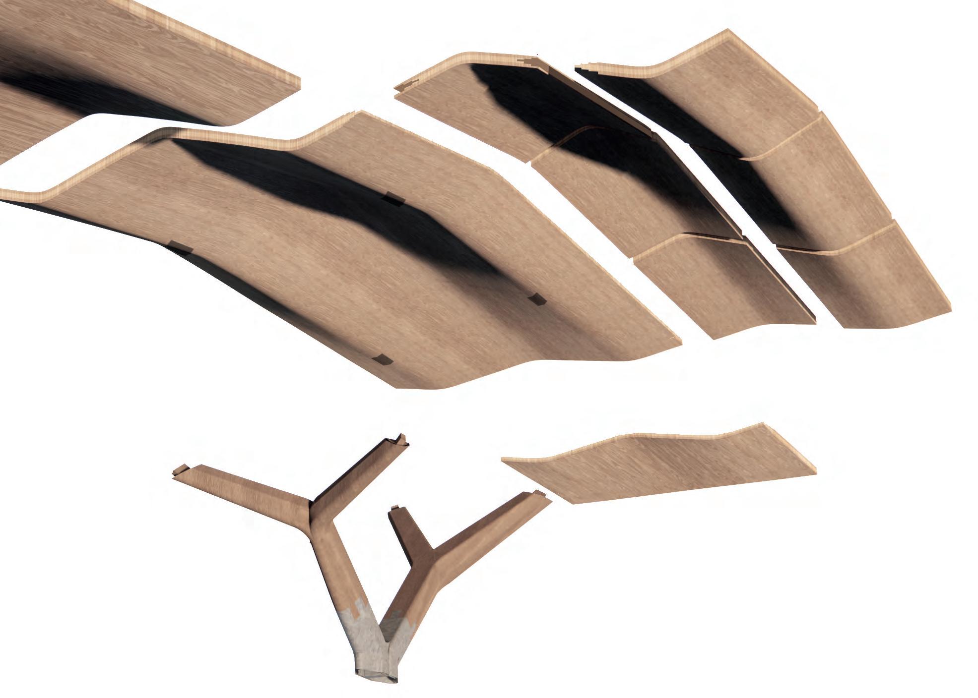
BUILD COMPONENTS
Components Folded
Bending the folds over cutting and reconnecting them offers the significant benefit of preserving material continuity, which directly increases structural performance. The natural fibre alignment remains unbroken across the fold allowing the material to carry forces efficiently. This reduces stress concentrations and weak points that typically arise at joints
Tangents
Tangents
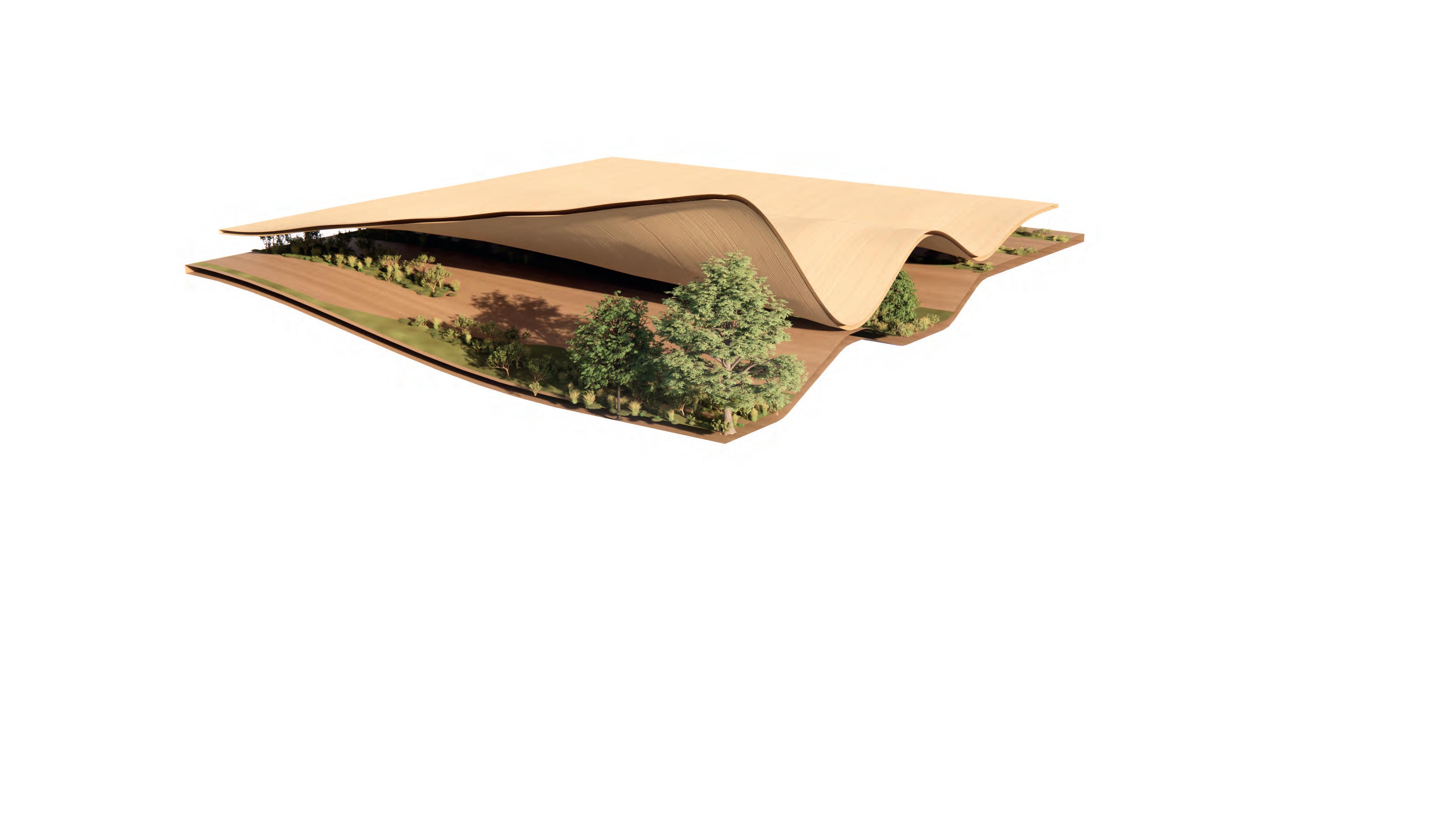
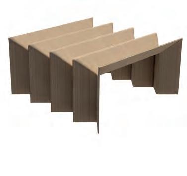
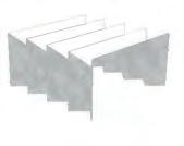
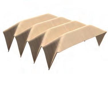
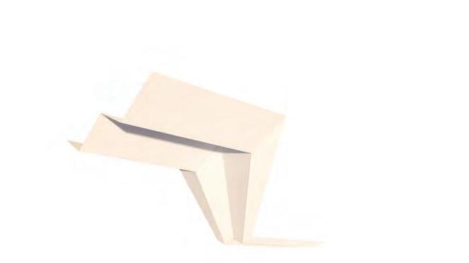
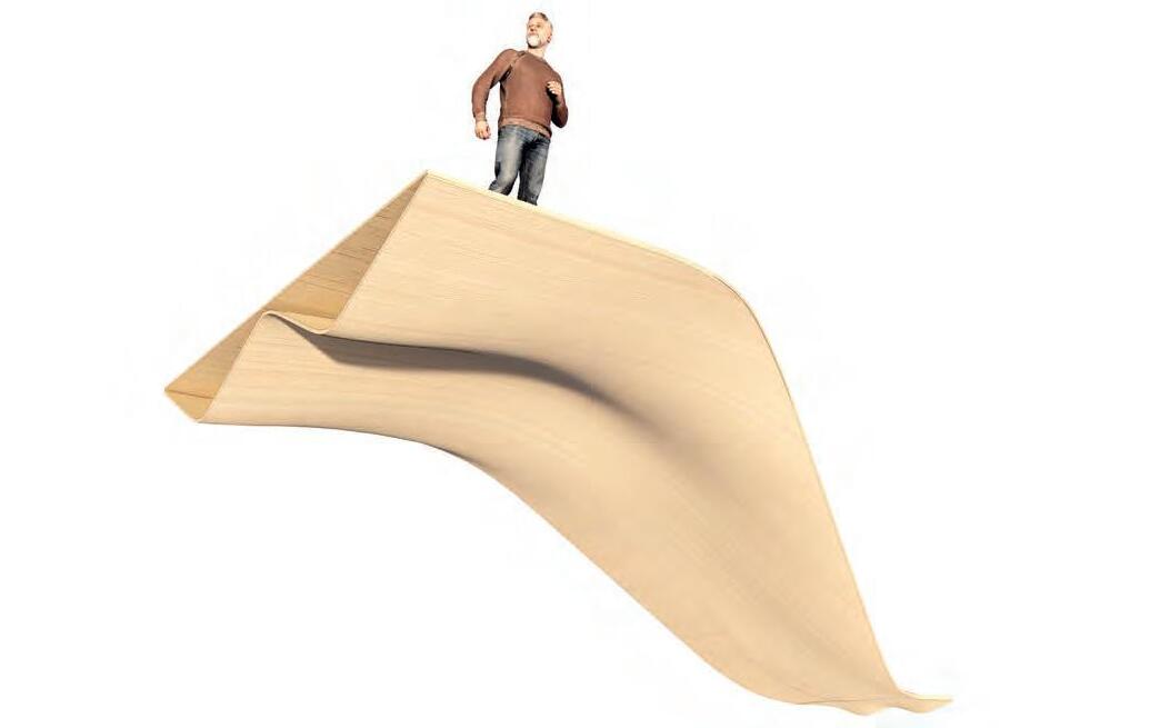
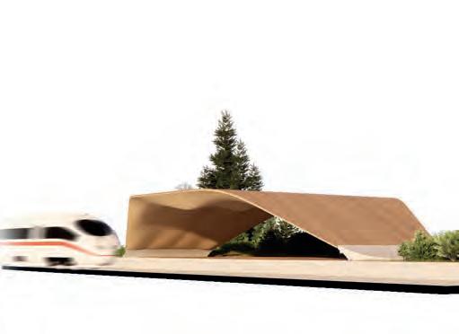
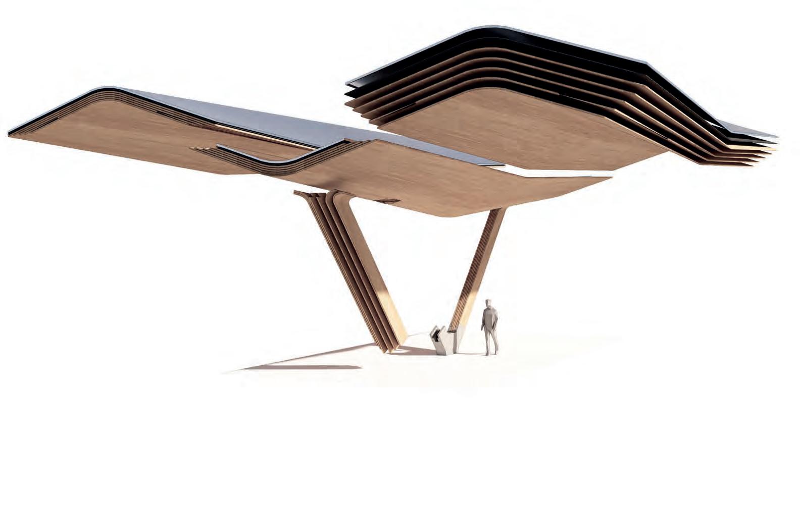
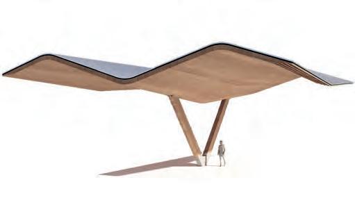
FOLDING TUBE FRAGMENT
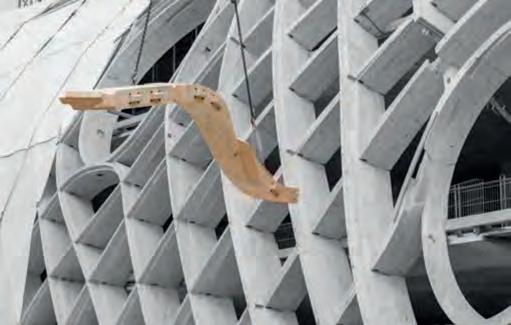
Structural Through Folds
This fragment uses structural folds to increase the stiffness of the tube design roof. The idea is that through the folds material can be reduced as inertia is increased. The fragment is set into a natural environment to understand it’s integration into the surrounding.
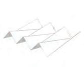
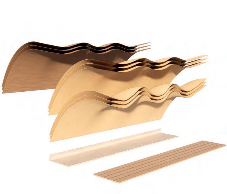
Exploded
Tangents
Concrete
Flooring
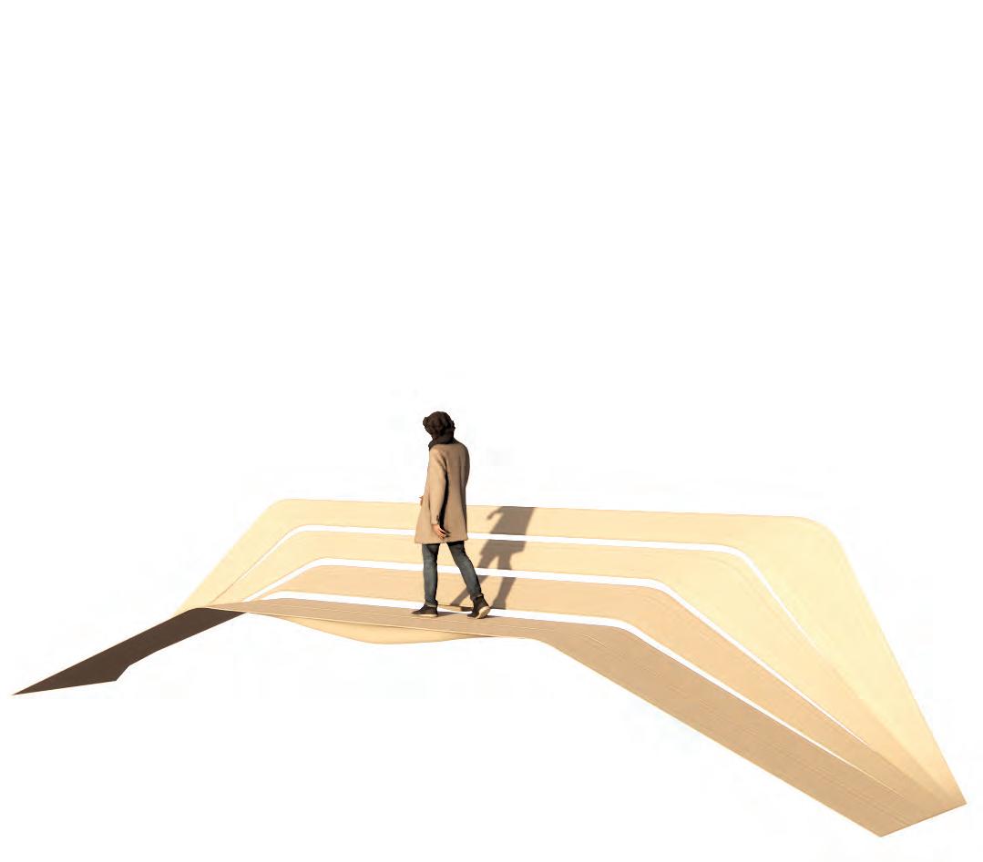
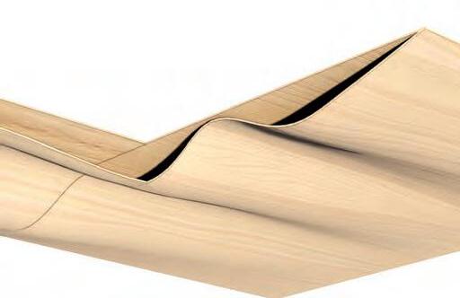
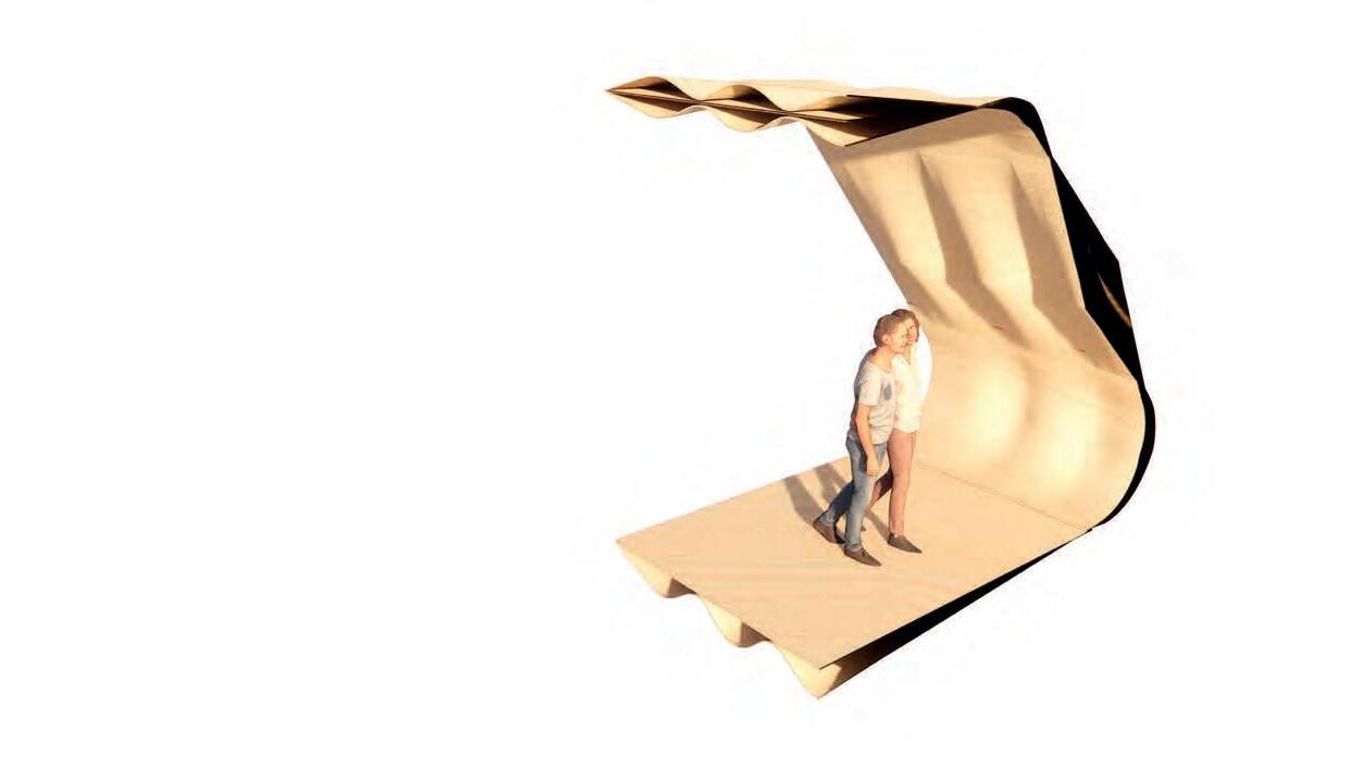
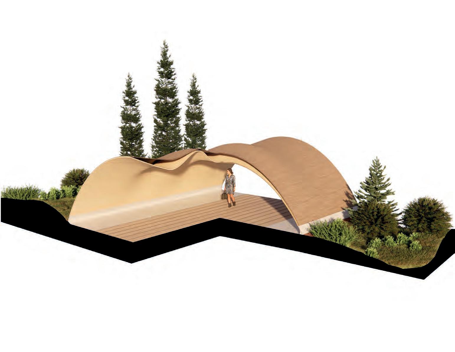
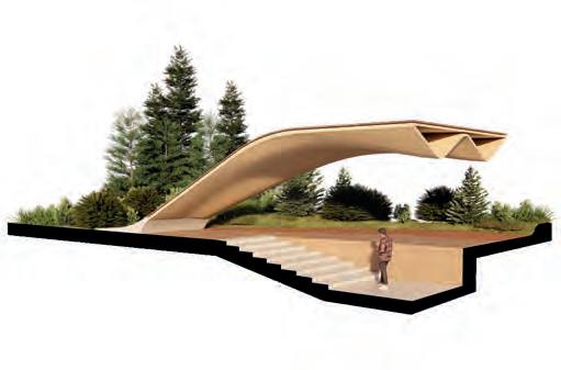
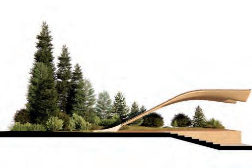
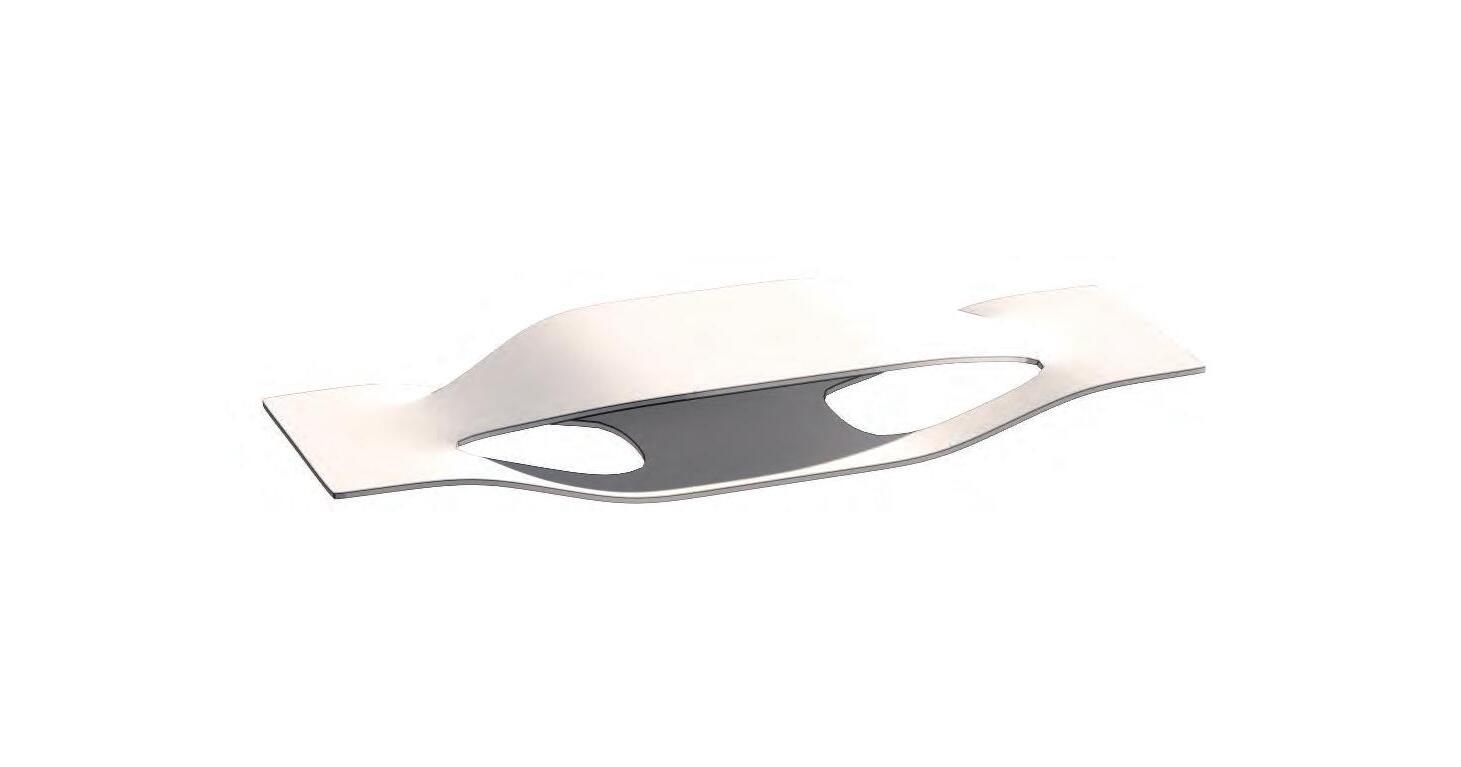
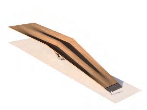
FOLDING ARCH FRAGMENT
Structure Through Folds
This fragment uses the same principal of structural bending for increased inertia and stiffness on a ground to floor/ ground to roof fragment geometry. In difference to the previous fragment bending only occurs on the horizontal plane reducing the amount of double curvature.
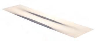
FRAGMENT
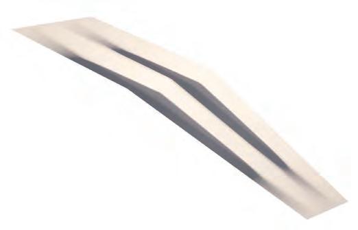
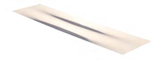
STRUCTURAL ANALYSIS
In the digital analysis, performed with Karamba3D, a 10 N load was uniformly distributed over the surface. Two simulations were run. The results show that, at the same material thickness, the optimized corrugated surface deflects only 0.56 mm under load, compared to more than 1 mm for the simple surface.
Tearing
Debonding Load
Multi-Support Point Loads
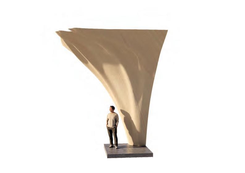
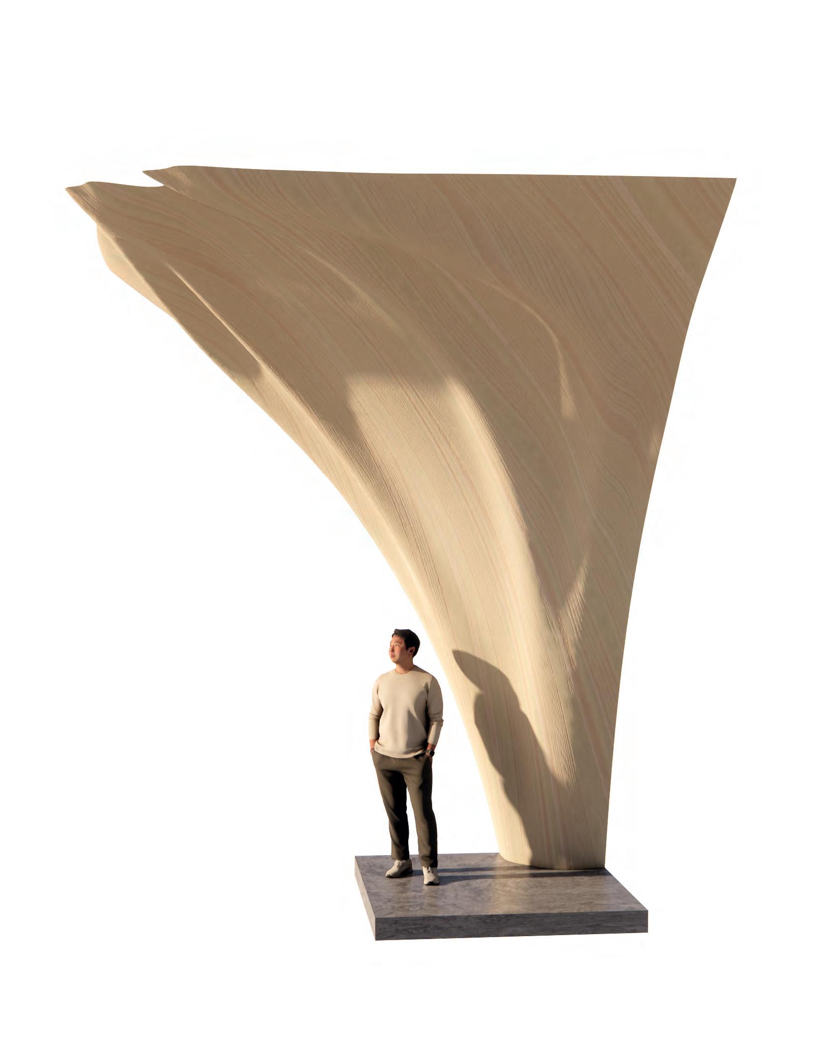
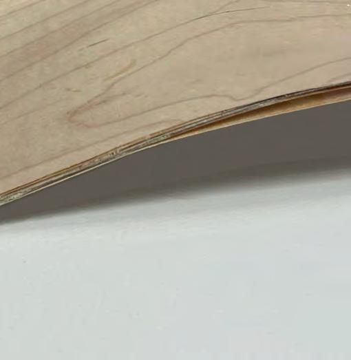
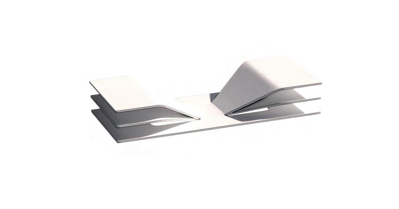
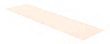
PHYSICAL PROTOTYPE FRAGMENT
Structure Through Folds
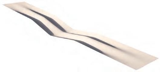
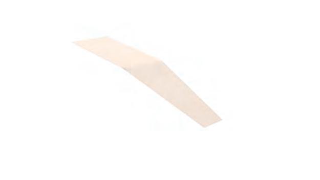
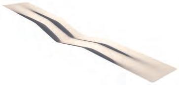
The fragment measures 300 mm in length and 150 mm in width and uses a 60 mm bending radius for continuity. The geometry is symmetrical along both axes, and the physical prototype represents a half-section of the full model. Following best practices from previous tests, positive and negative moulds were 3D-printed, and 0.4 mm birch veneers were laminated to a total thickness of 5 mm.
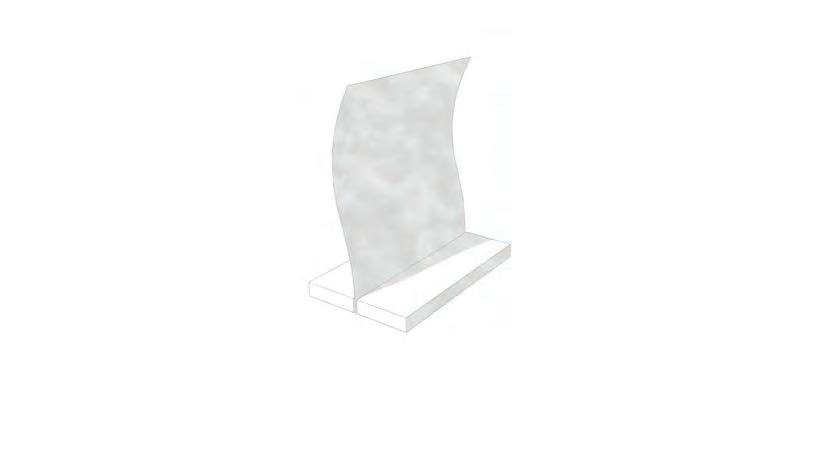
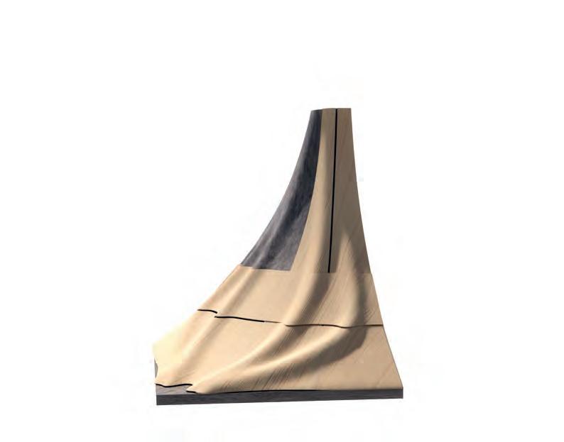
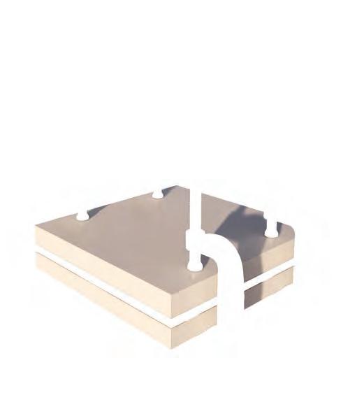
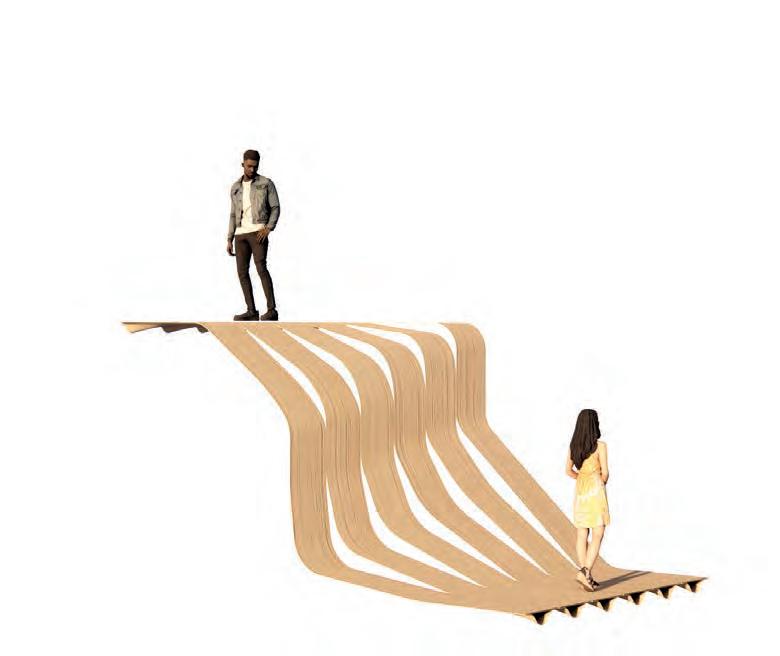
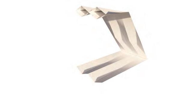
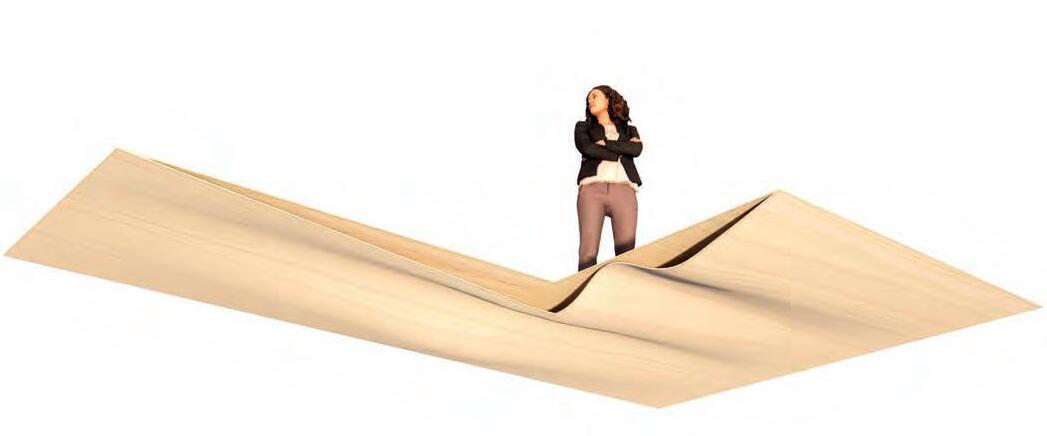
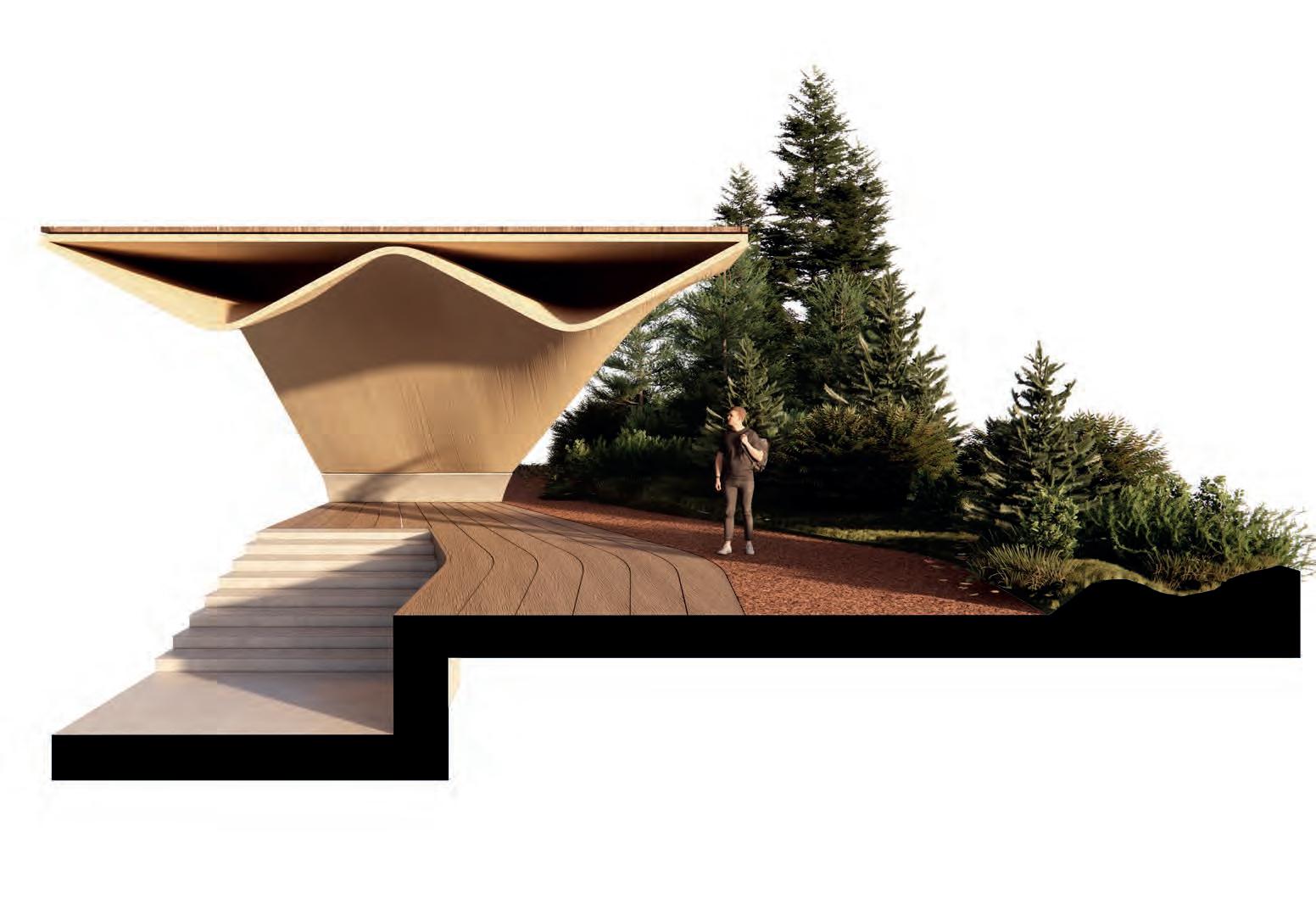
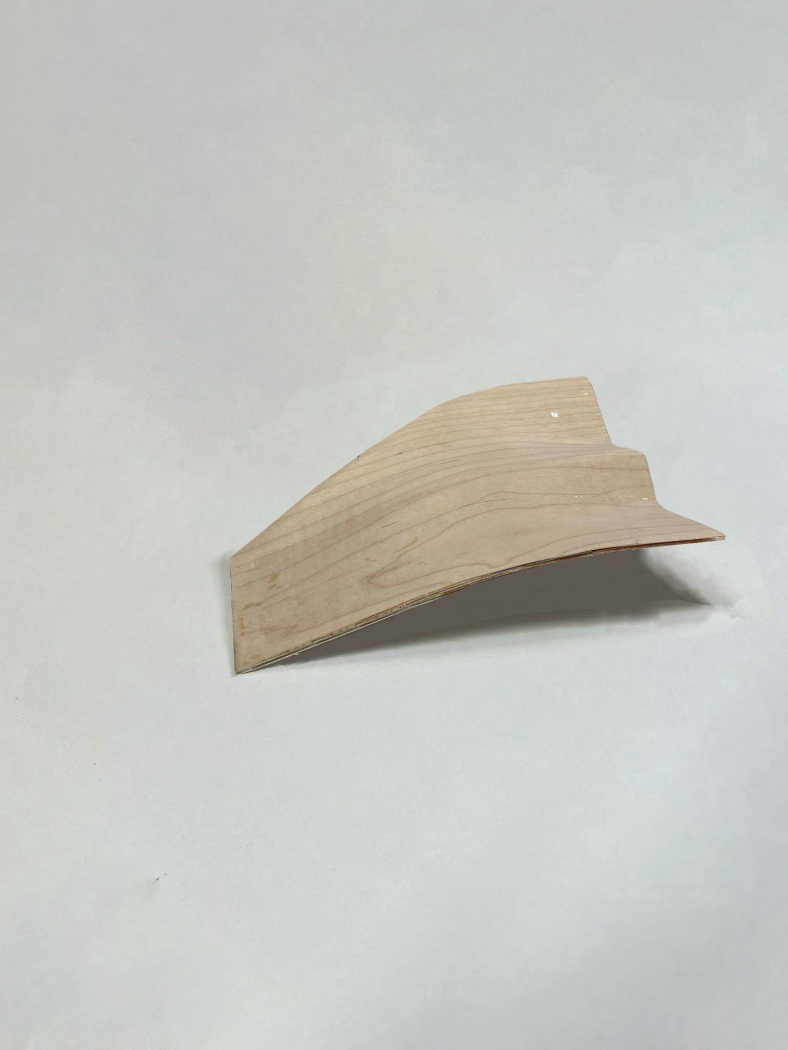
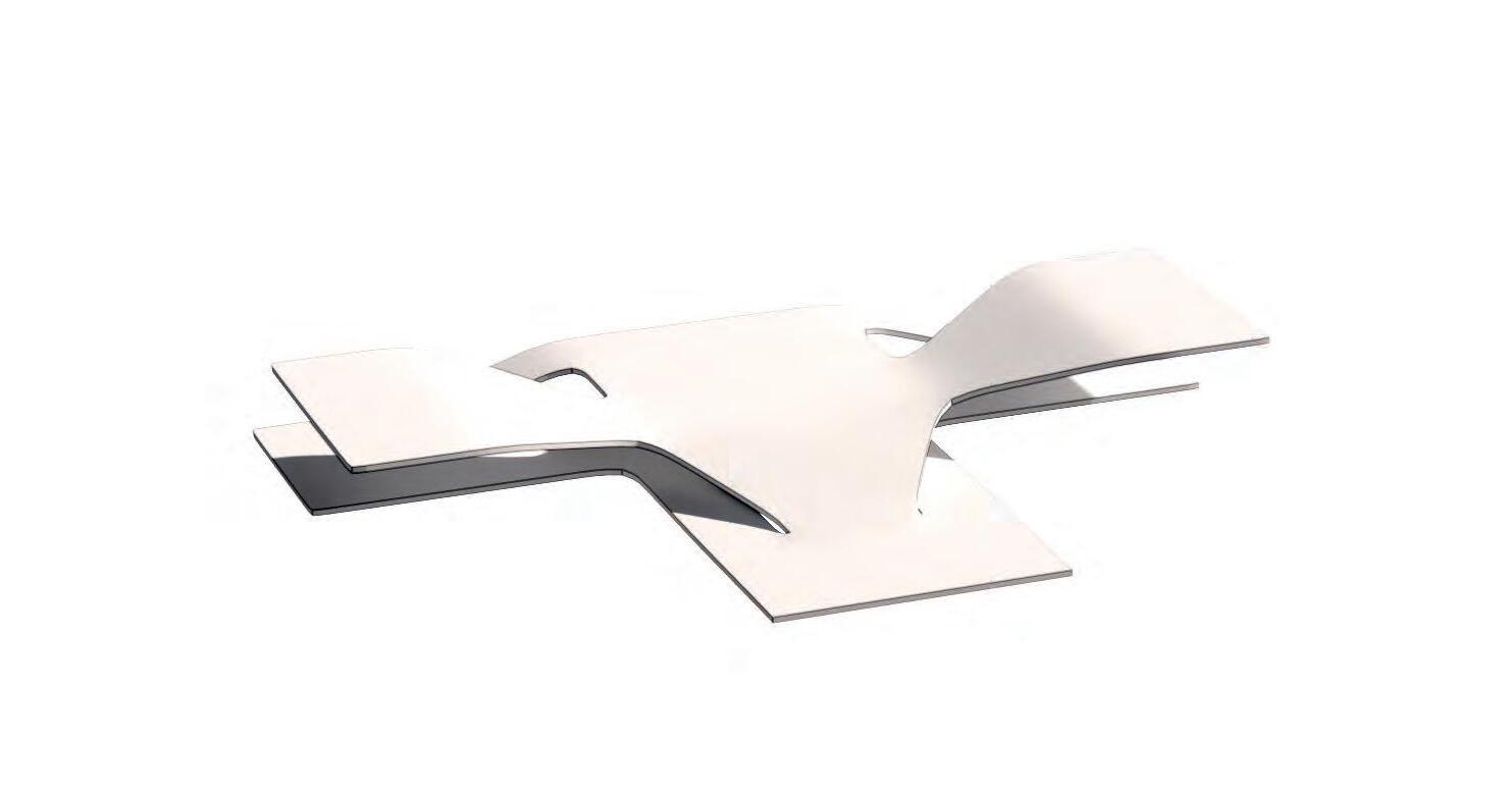
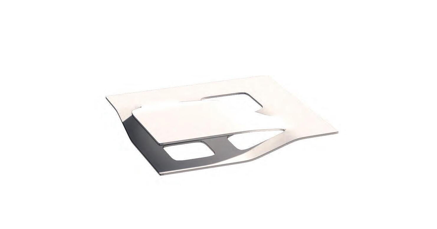
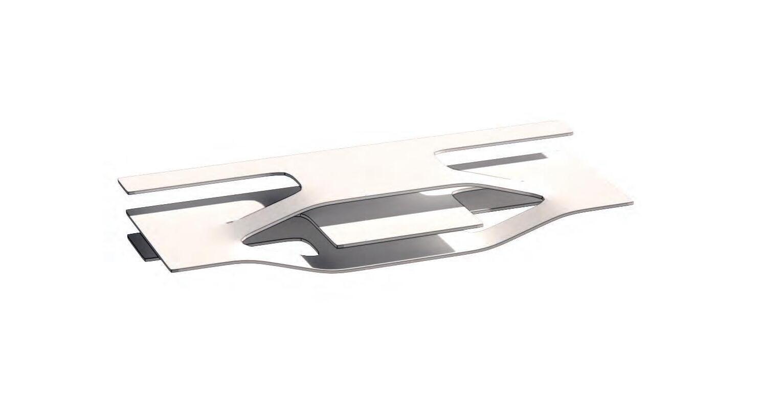
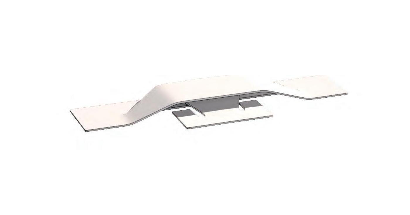
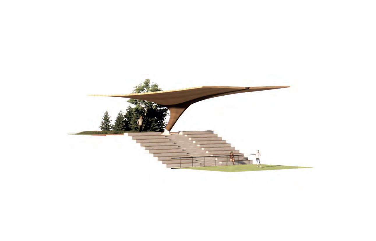
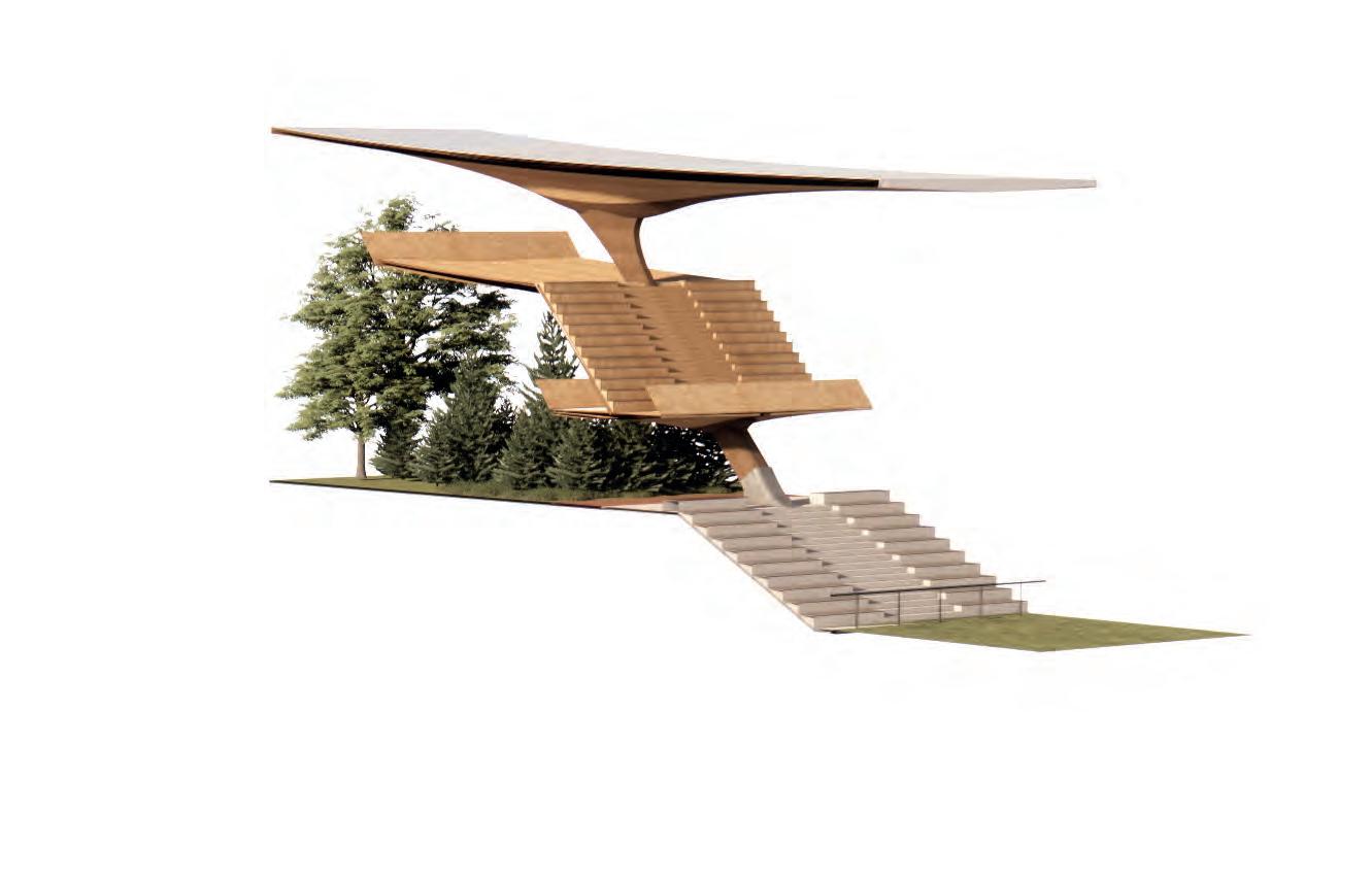
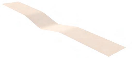
SURFACE INTEGRATION FRAGMENT
Structure Through Folds
This fragment demonstrates how the previously established principles of bending can be applied to this tectonic. The surface connects a lower and upper level with a mezzanine, incorporating a fluid transition into the stair elements. On horizontal spans, the cross-section is thickened through bending, as demonstrated in earlier fragments.
Fluent Surface
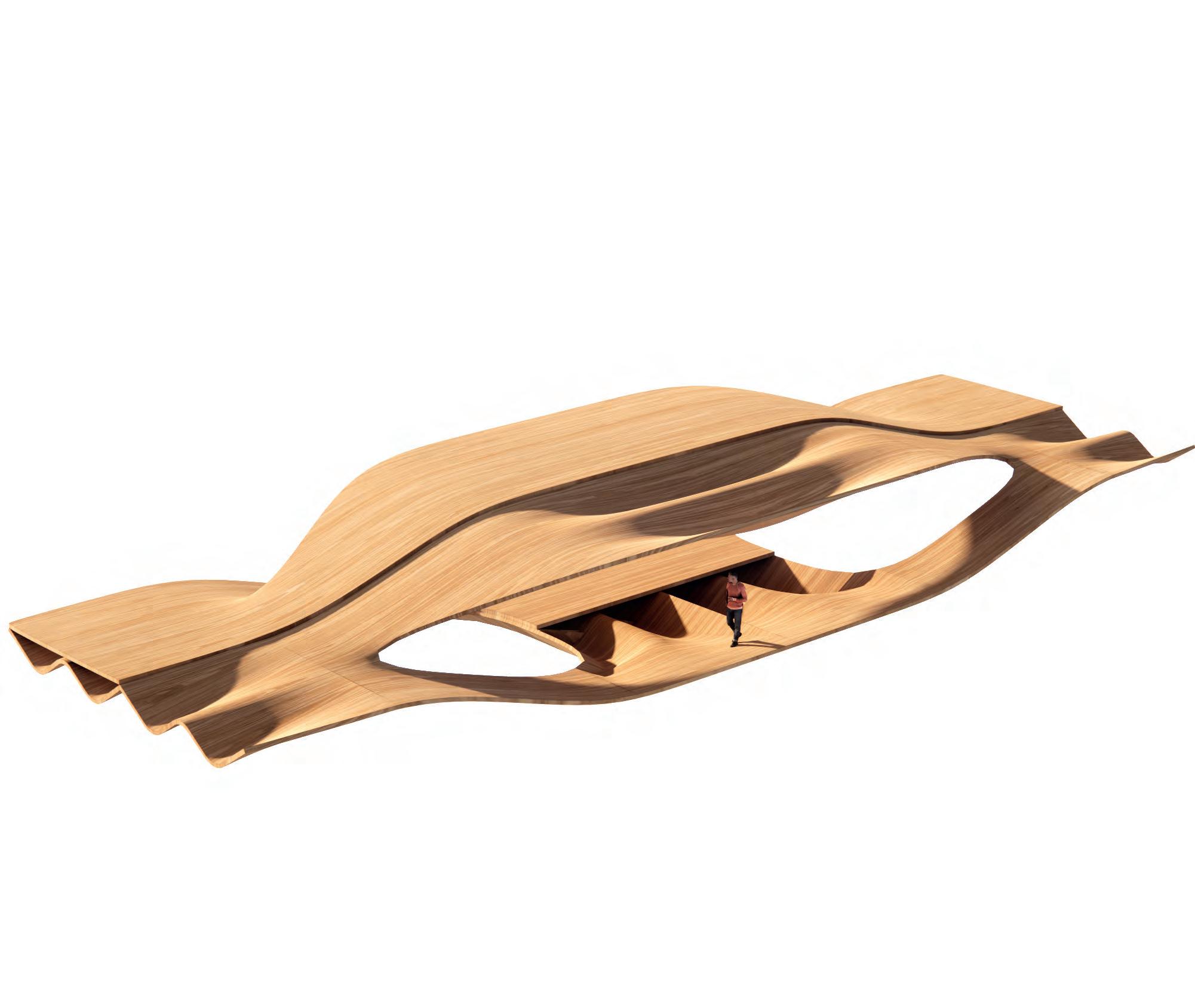
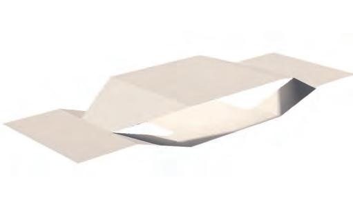
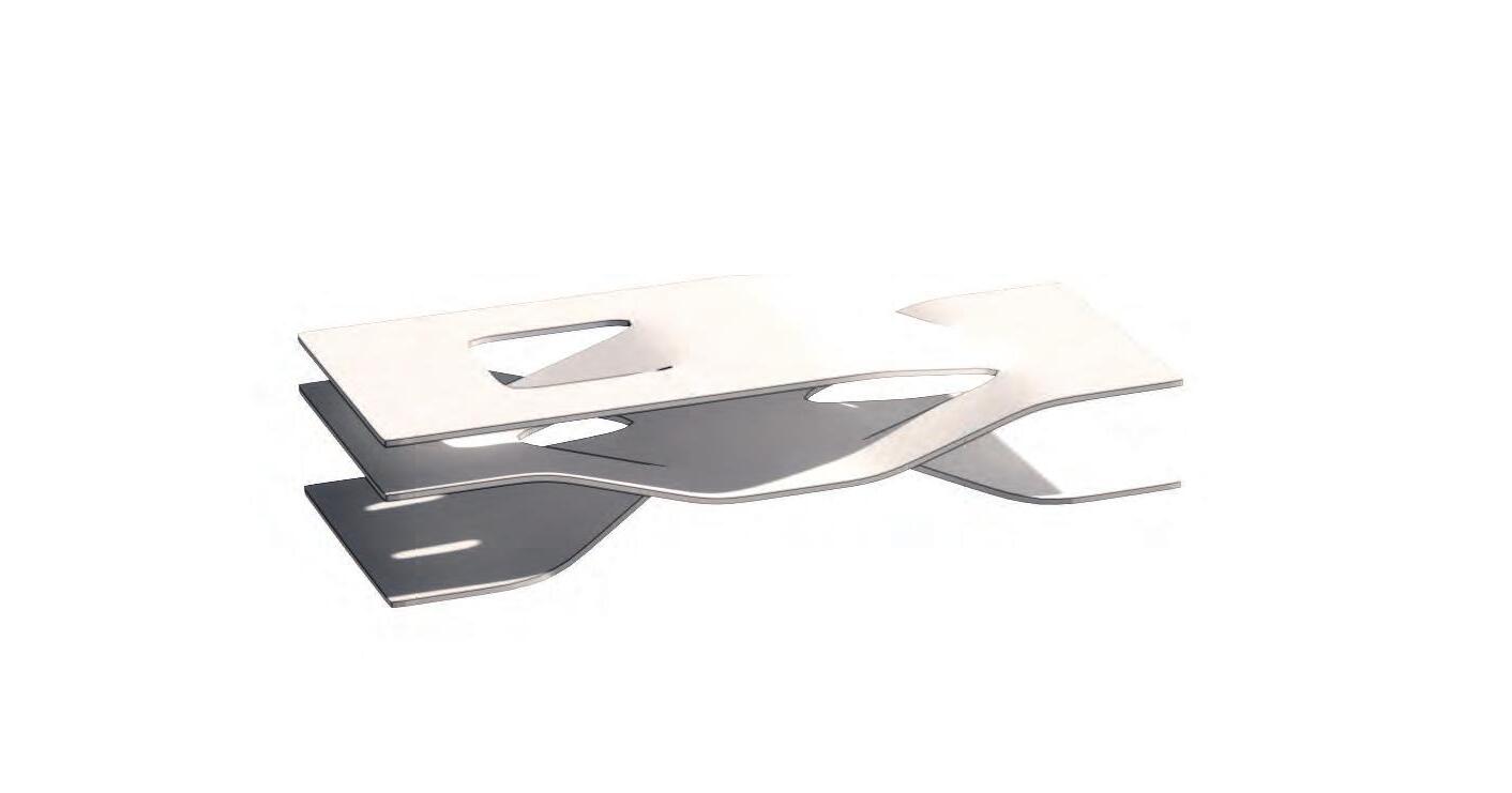
FRAGMENTS
Integrating Spaces
The use of continuous structural surfaces enables the development of a new tectonic, as illustrated in the fragments above. Floors, walls, stairs, and roofs can be seamlessly integrated into a single, unified geometry.
Compression Tension
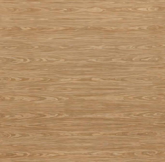
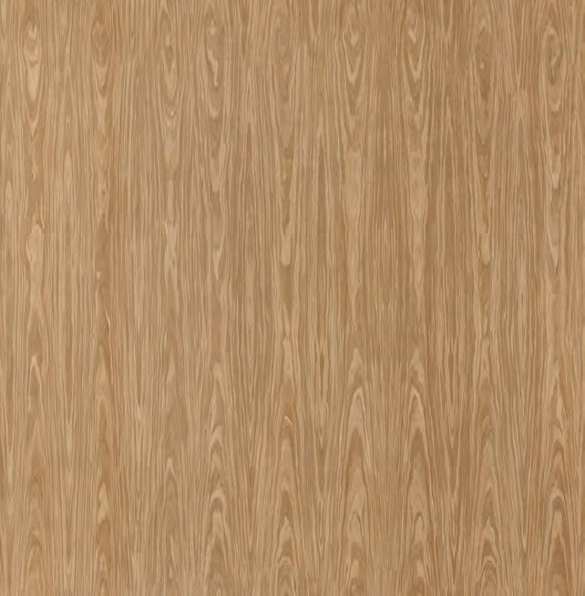
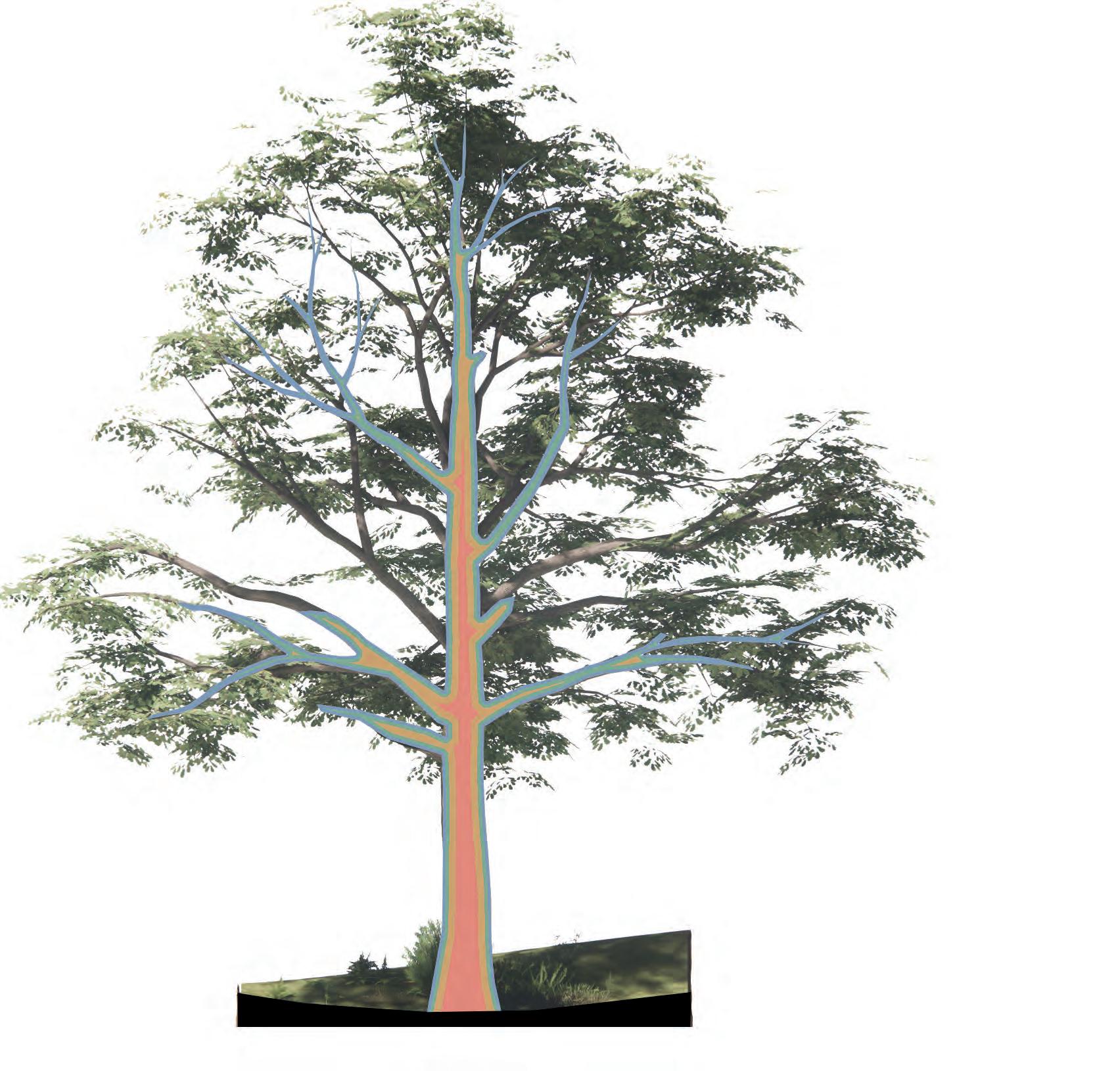
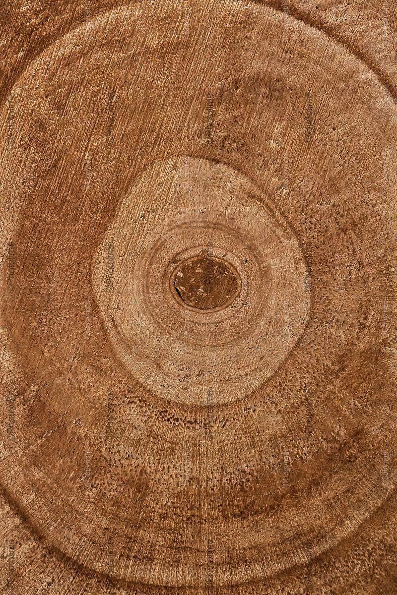
WOOD MATERIAL PROPERTIES
Cellular Structure
Wood is a composite material made up of the fibrous structural tissue of trees. It primarily serves to support the plant mechanically, transport water and nutrients, and store biochemical energy. Structurally, wood is composed mainly of cellulose, hemicellulose, and lignin. Cellulose fibers provide tensile strength, while lignin acts as a binder, adding compressive strength and rigidity.
Hardwood
Cork
Sapwood
Outer Bark
Sapwood Periderm
Hemicellulose
Living Phloem & Vascular Cambium
Cellulose Heartwood
Lignin
Vessels Fibres
Medullary Ray
WOOD PROCESSING INTEGRITY
In modern construction there are a number of different ways wood can be processed. Each method has its distinct production steps and technological applications. Ultimately, structural considerations break down to differences in material control and material integrity.
Glue Laminated Timber Cross Laminated Timber
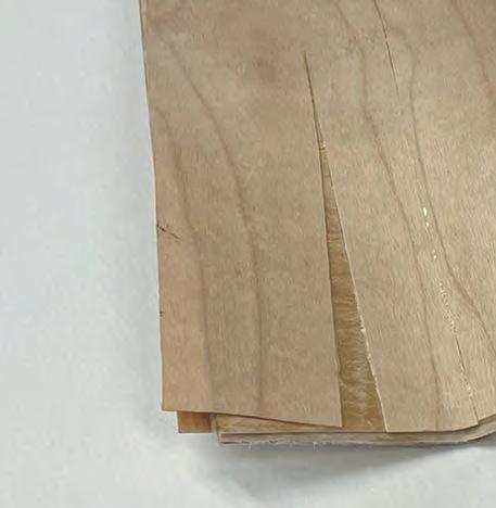
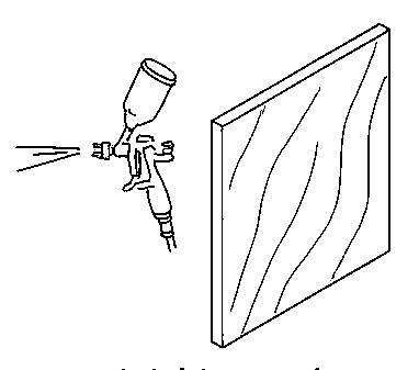
VENEERING
Trunk to Product
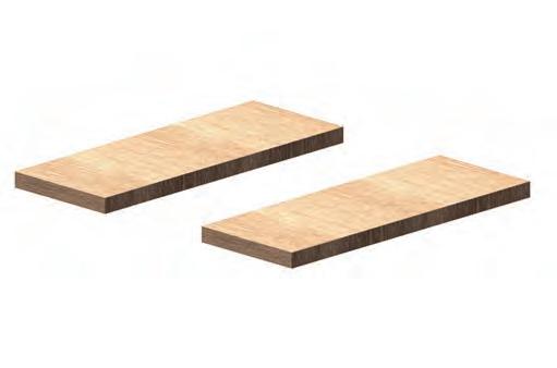
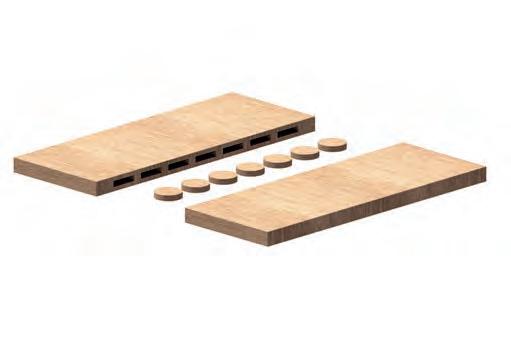
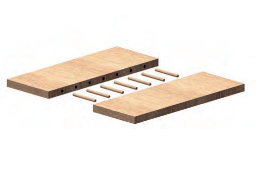
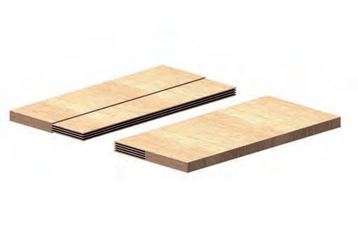
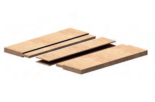
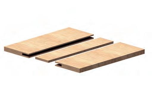
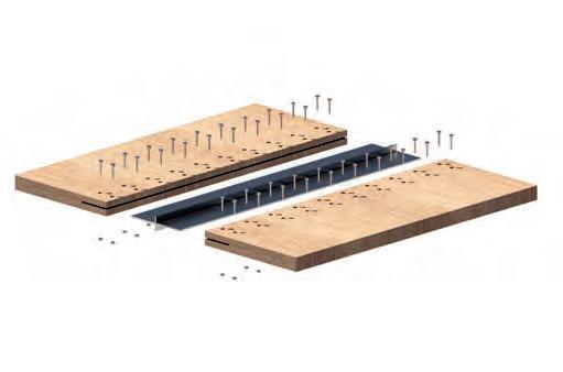
WOOD SURFACE SPLICING
To overcome the natural size limitations of wood due to tree size and thickness the correct design and use of wood joinery is required for any form of large scale construction. Designing wood joinery poses challenges at any scale due to the material’s anisotropic properties although the effects are increased with bigger scale.
Lamella
TIMBER CONNECTION
DETAIL AND COMPONENTS
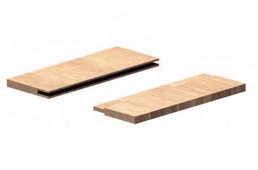
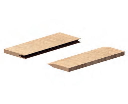
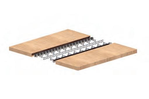
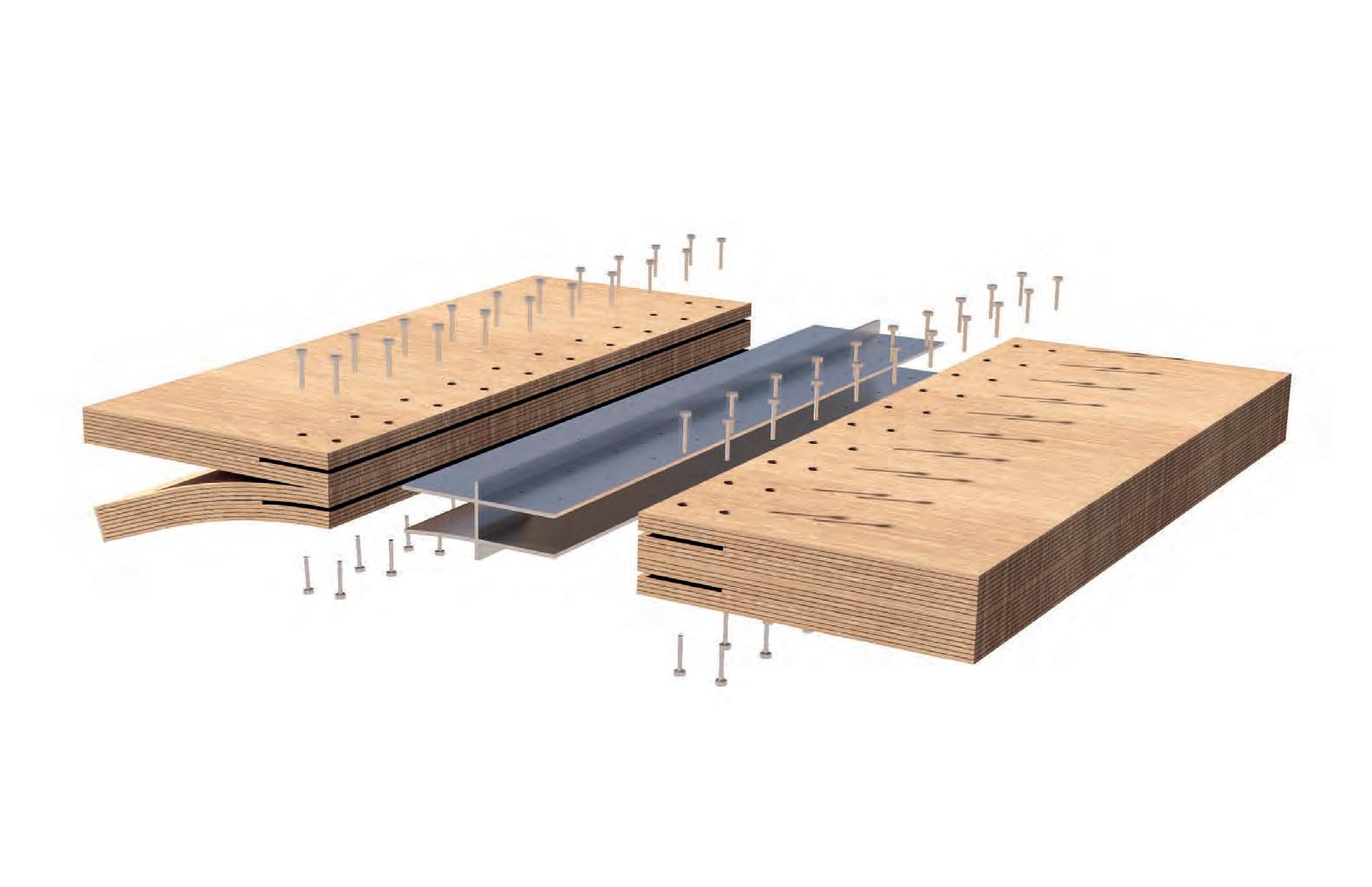
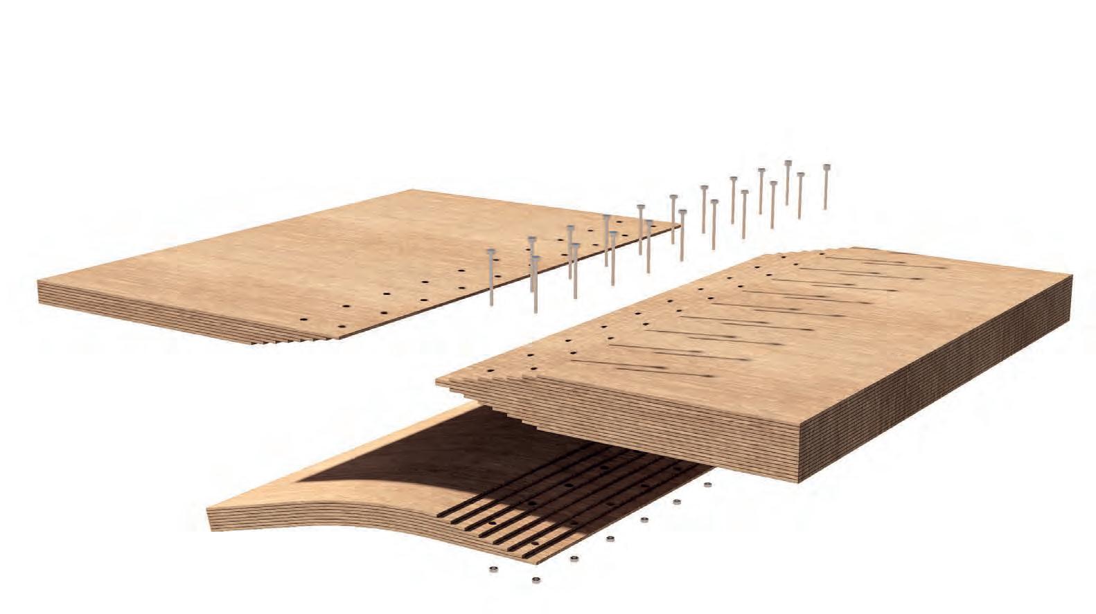
Stepped Tongue and Grove Joint
Lamella Layers
ROOF SUPPORT
DETAIL AND COMPONENTS
Surface Lamination and Support Structure Top Layer
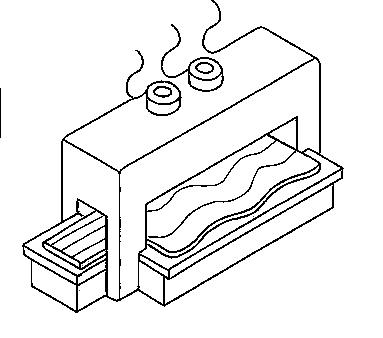
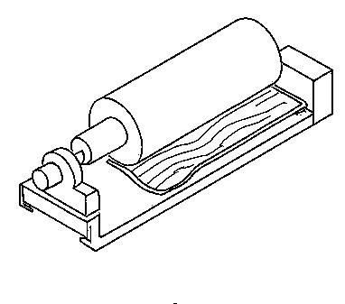
A hydraulic glulam press works by using hydraulic cylinders to apply uniform pressure to layers of glued wood, bonding them together to form strong, laminated beams. The process involves stacking glued wooden lamellas in the desired configuration and placing them in the press, where pressure is maintained until the adhesive cures. Once the curing is complete, the pressure is released, and the laminated beam is removed from the press, resulting in a durable and robust construction material.
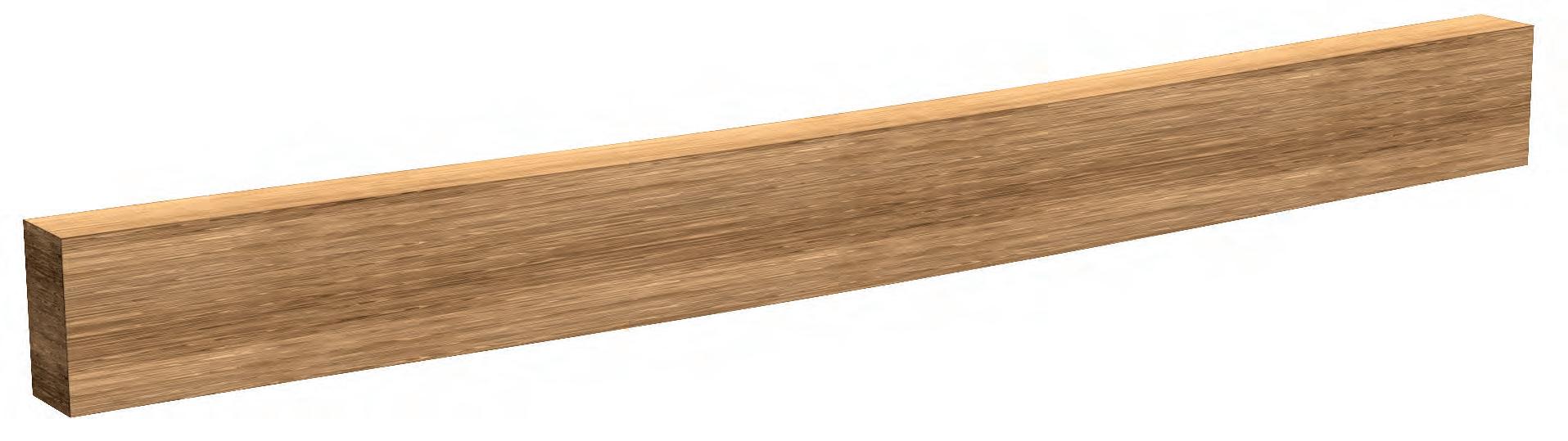
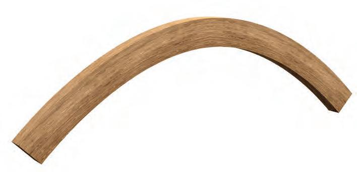
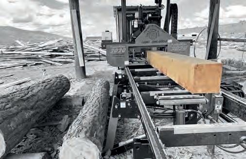
BENDING TIMBER
GLULAM BEAMS
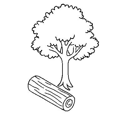
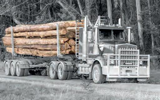
From Log to Construction
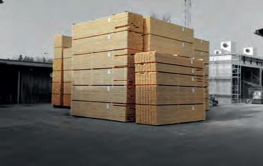
The process of glulaminating begins with logs being sawn into thin layers of wood called lamellas. These lamellas are dried, planed, and coated with adhesive before being stacked in the desired configuration. The stack is then placed in a hydraulic press, where uniform pressure is applied to bond the layers together, forming strong, laminated beams. Once cured, these glulam beams are cut into size ready for construction.
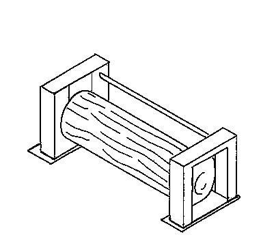
Trees Cut into Logs, Soaked & Dried
Lumber
Cutting of Lamellas
Bending and Glueing of Lamellas
Cutting & Post Processing
On Site Assembly
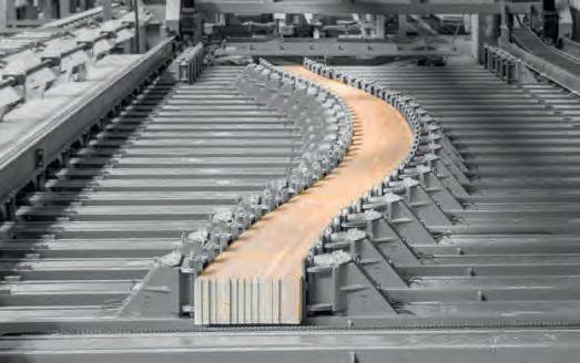
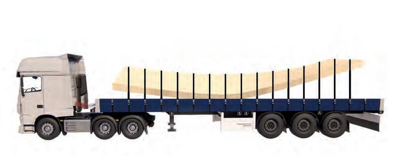
Forming Deformation
of Pressed Building Components
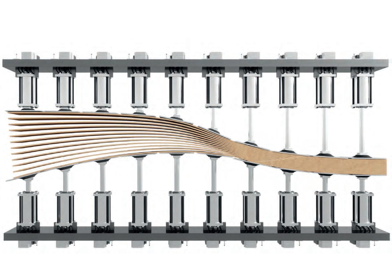
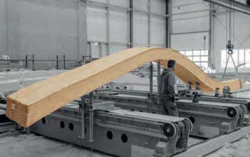
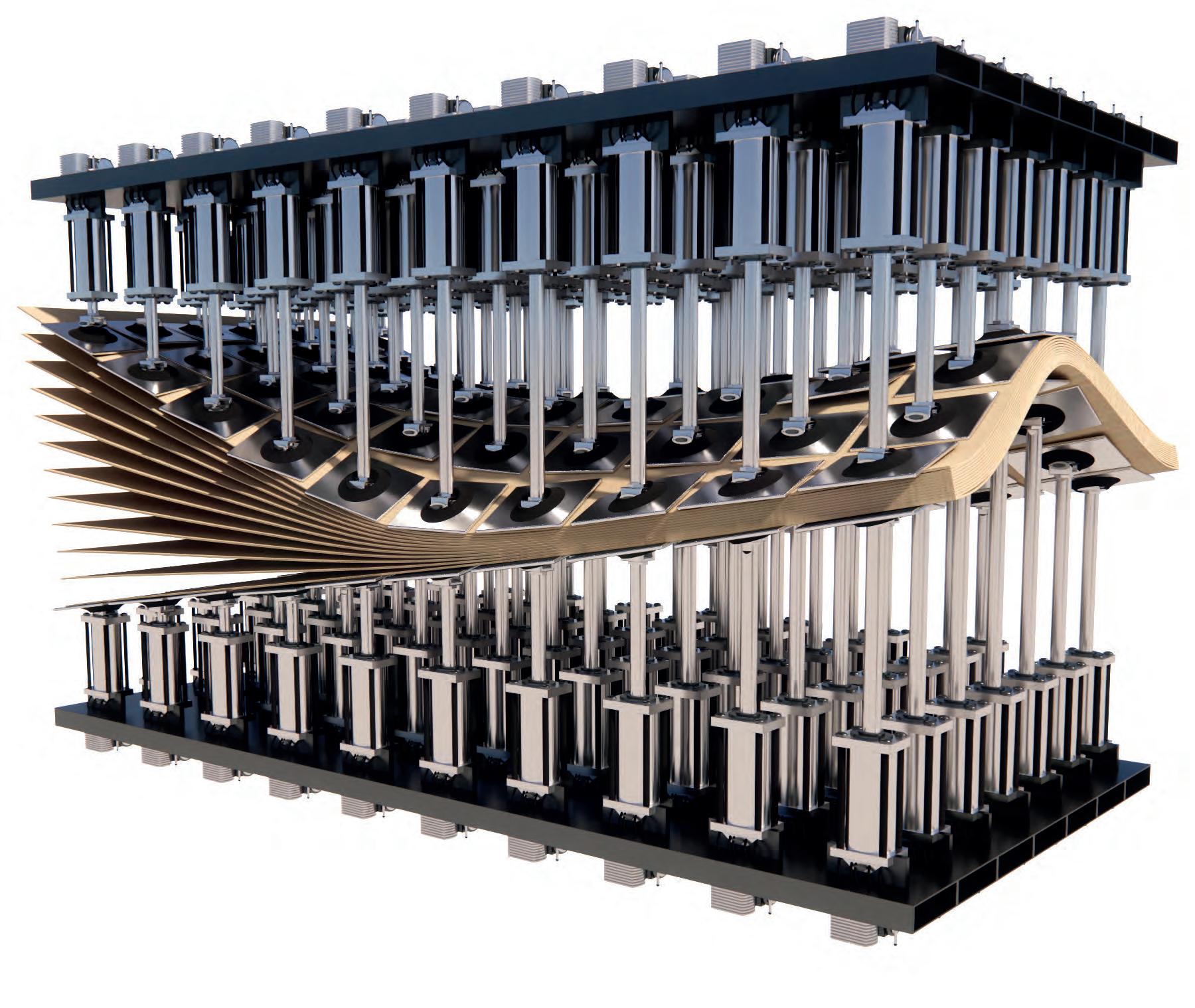
SURFACE BENDING
PARAMETRIC PRESS
From Log to Construction 0
The surface lamination press uses the same principles as a flexible glulam beam press only on a 3 dimensional scale. This technology does currently exist but mostly on the furniture scale. Outside of financial considerations there is no reason why this technology cannot be adapted to a larger scale.
Sheet
Scale
RESEARCH & DEVELOPMENT
1893 e.V.
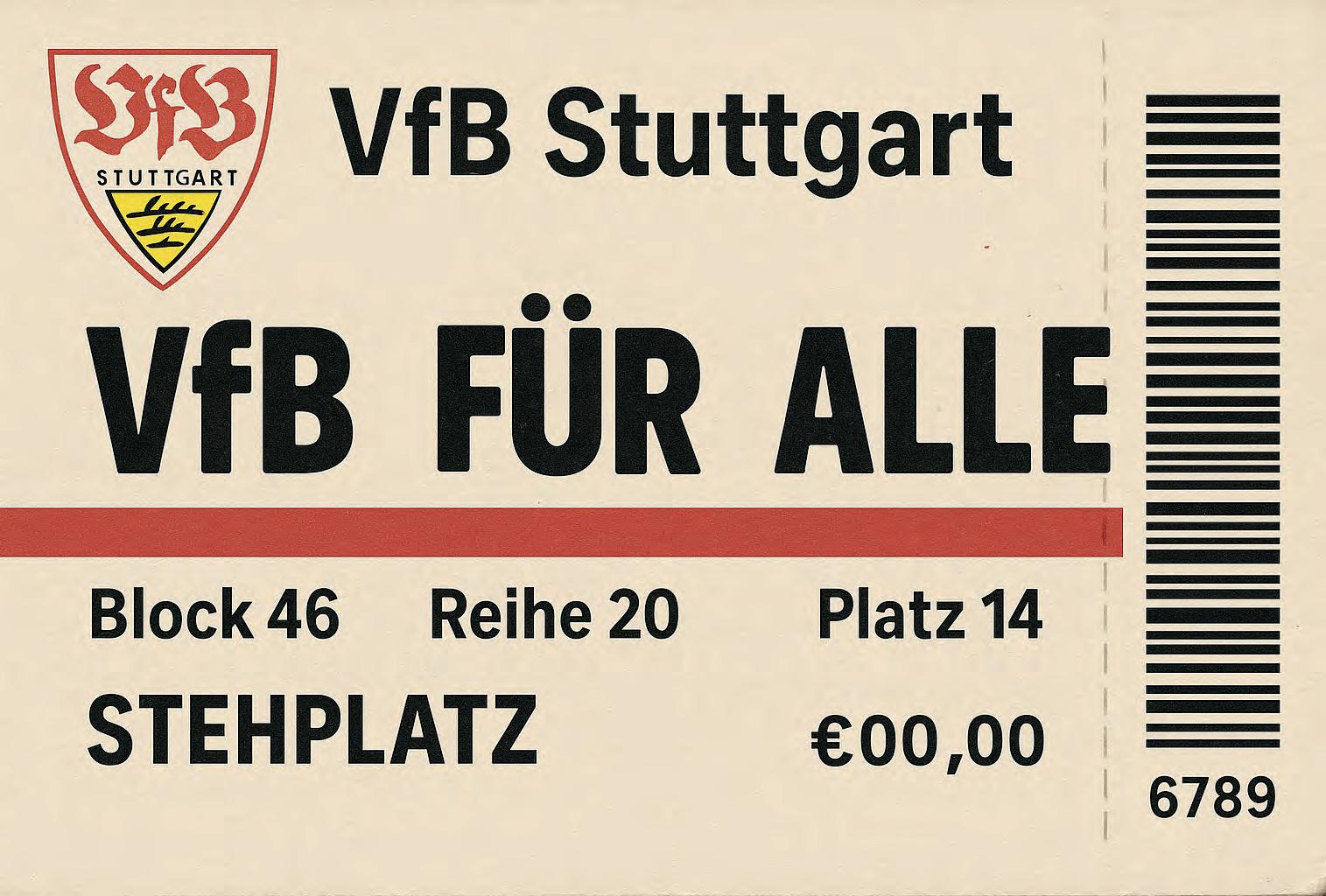
VFB STUTTGART
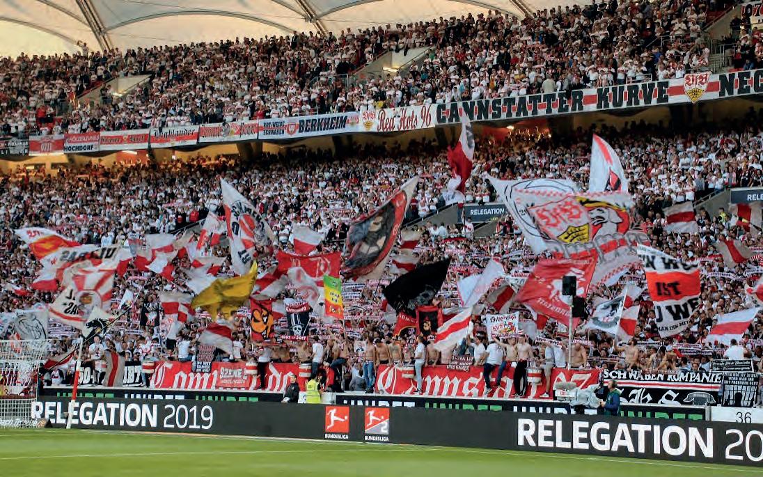
FOOTBALL RELIGION
Club, Community and City
Stuttgart e.V. is a cultural institution deeply embedded in the city’s identity. Founded in 1893, the club has a rich history and has become a symbol of pride for the people of Stuttgart and the surrounding region. It currently has over 100 000 members and is the biggest club in the state Baden-Württemberg.
VfB
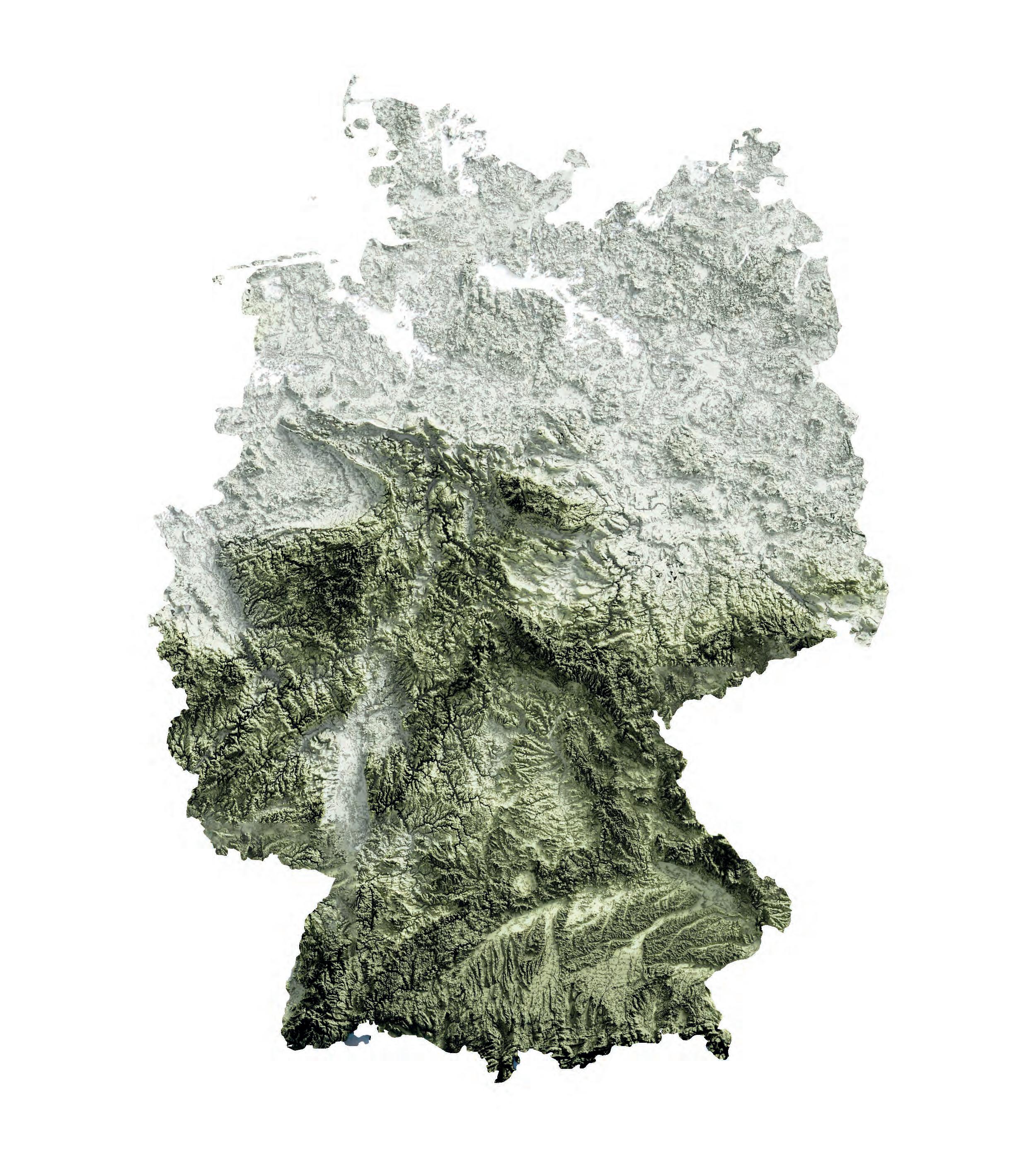
GERMANY
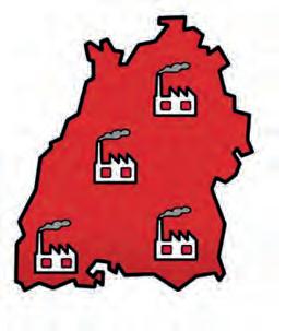
TOPOGRAPHY & CITIES Centre of Europe
Germany is at the centre of Europe. Not only geographically but also economically. Germany is the largest economy in Europe, acting as a key driver of economic growth and stability within the European Union. Its strong industrial base, particularly in automotive and manufacturing sectors, significantly contributes to the overall economic health and competitiveness of the region.
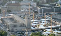
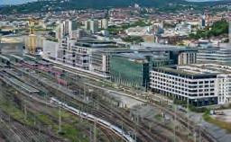
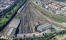
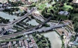
Stuttgart 21 has been in construction since 2010 is planned to open in 2025. It is a high-speed links from Stuttgart to other cities with the improvement of local infrastructure and replacement of the current terminal station. The current 16-track station is to be replaced by an underground 8-track station. The new station will open up a large site where currently tracks are laid in the Rosensteinpark.
Stuttgart Centre Old Train Station
Stuttgart After Stuttgart 21
New S-Bahn Stop
Station Under Construction
New Stuttgart Main Station Tracks Train Garage
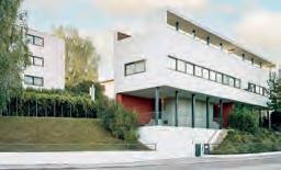
Weissenhofsiedlung Underground Station Rosensteinpark
New Train Bridges
Space Water City Site
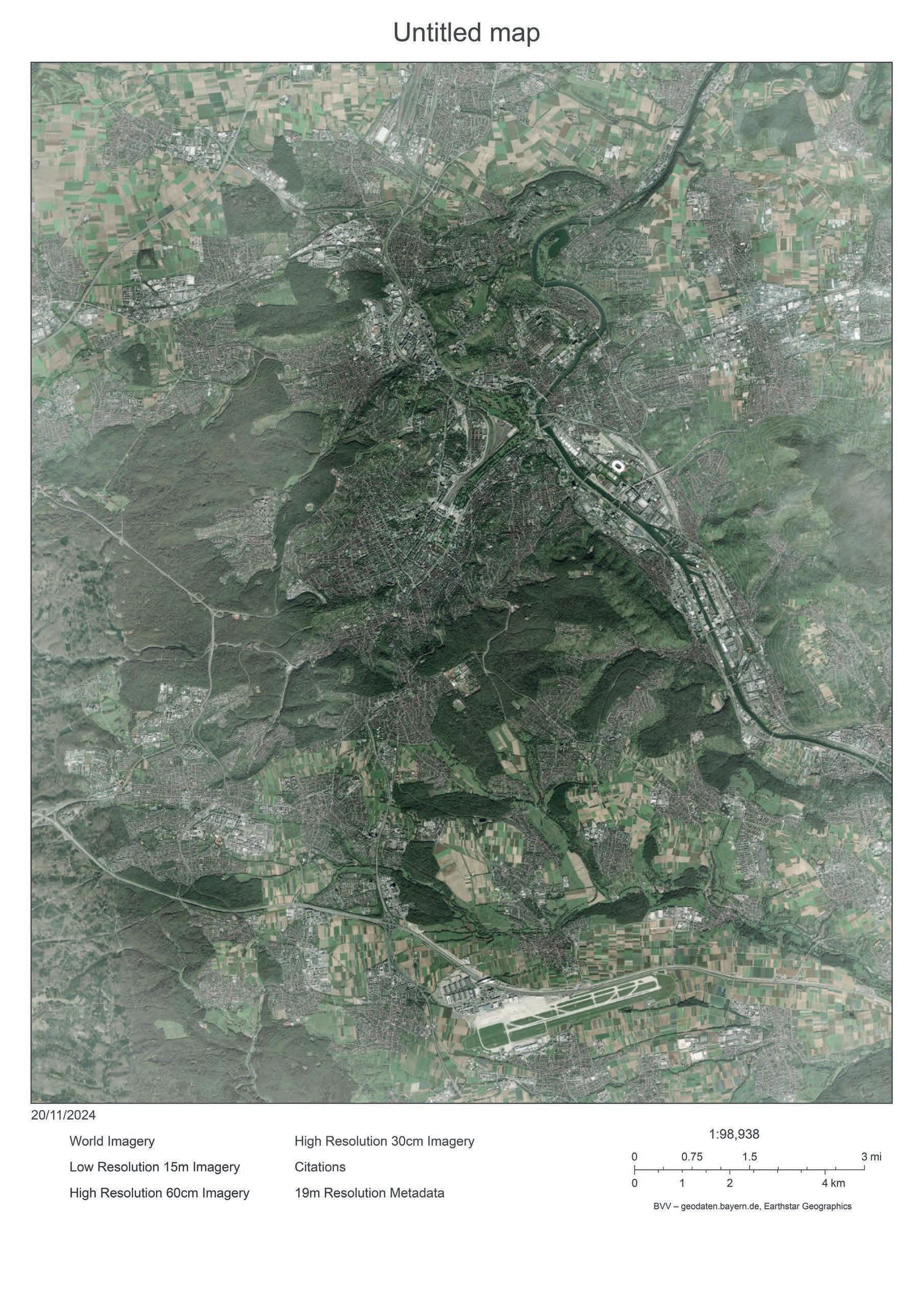
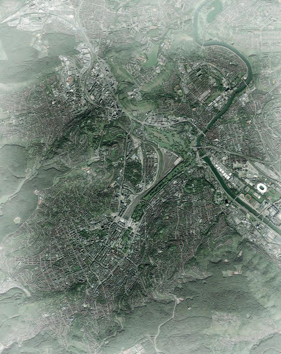
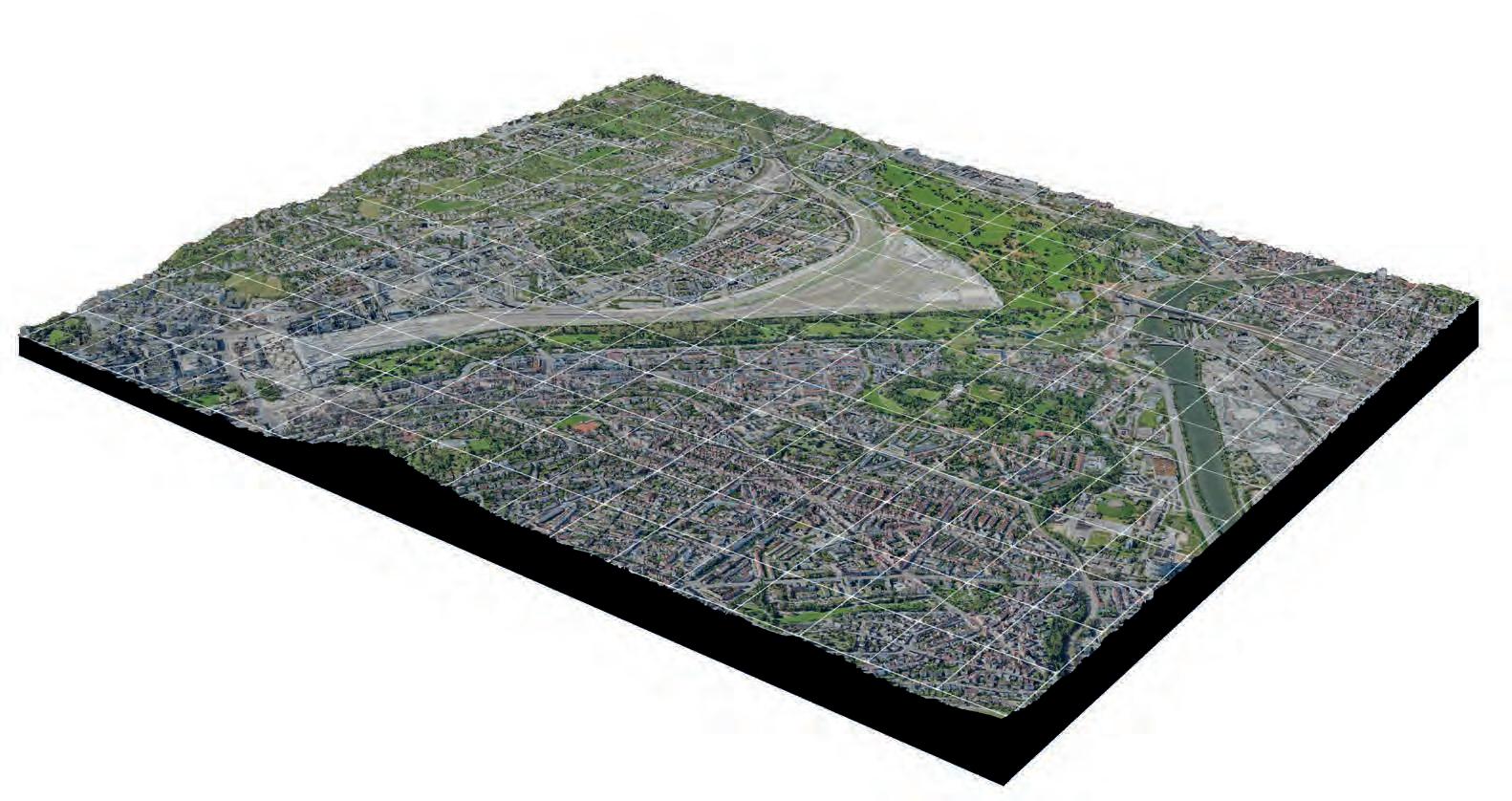
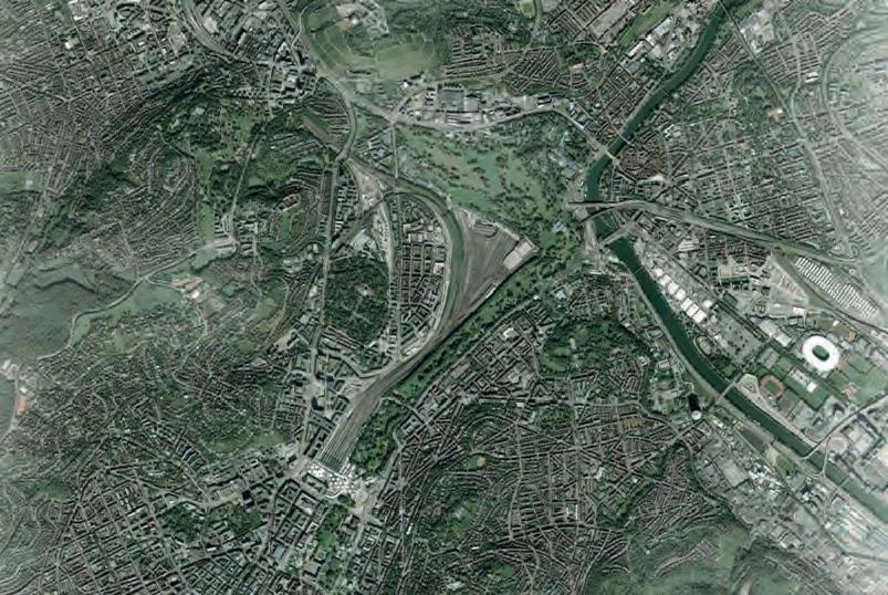
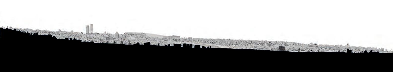
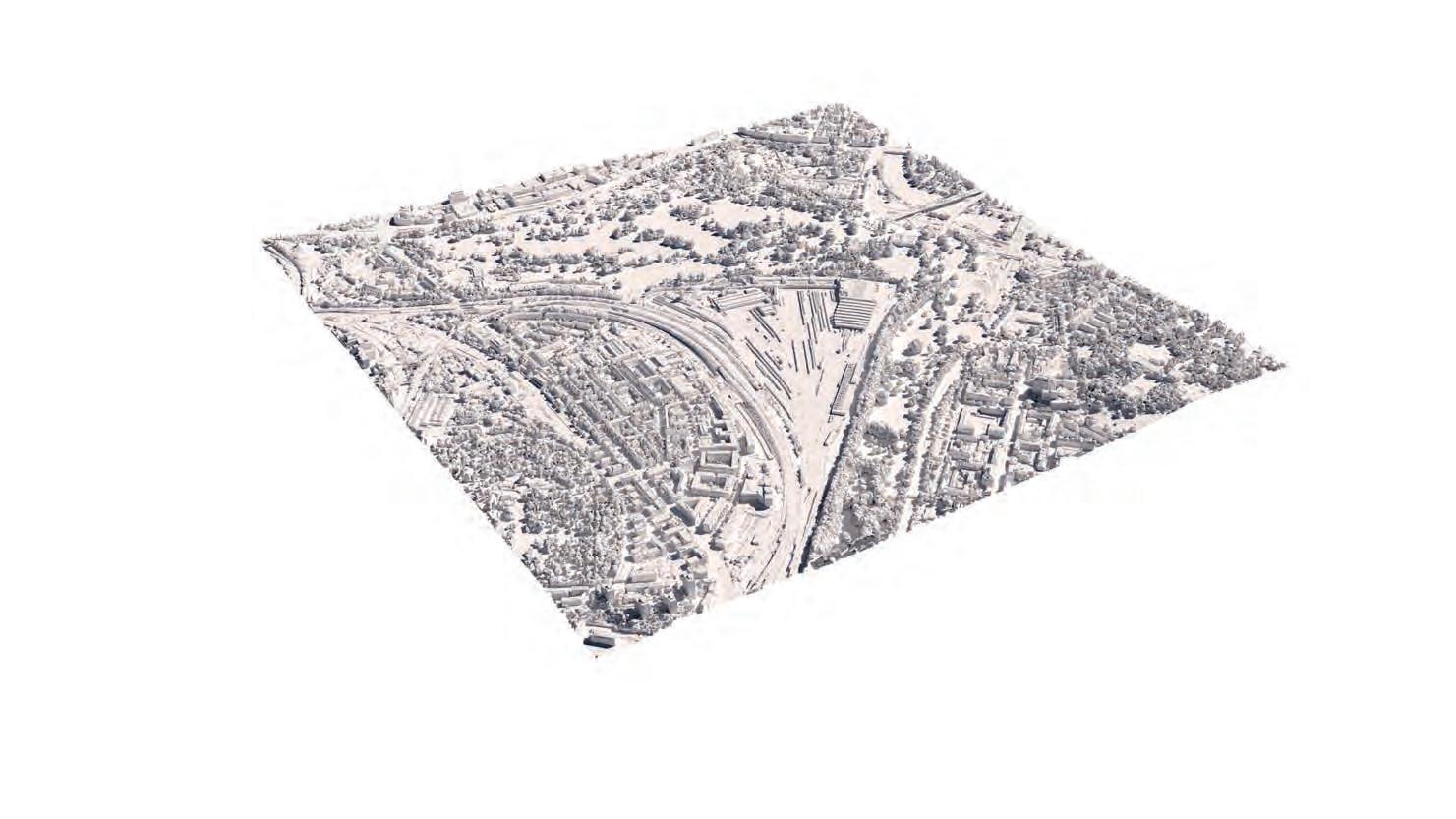
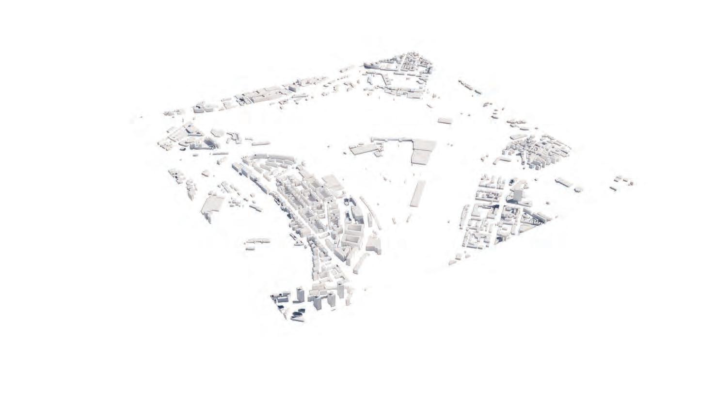
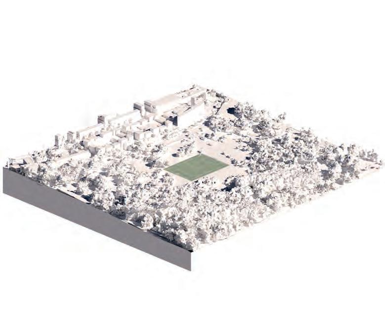
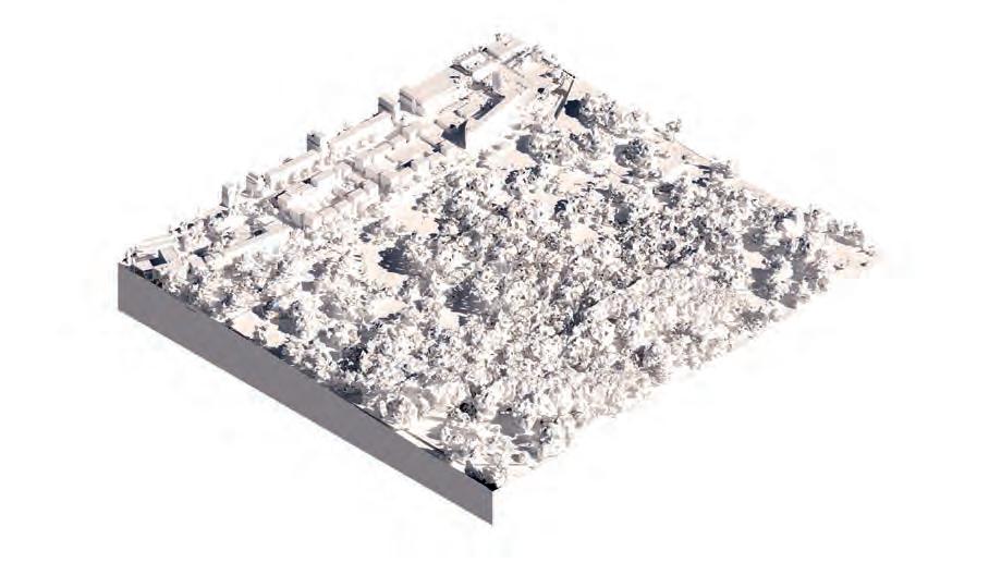
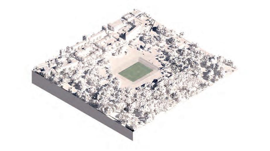
SITE INFORMATION CITY VALLEY
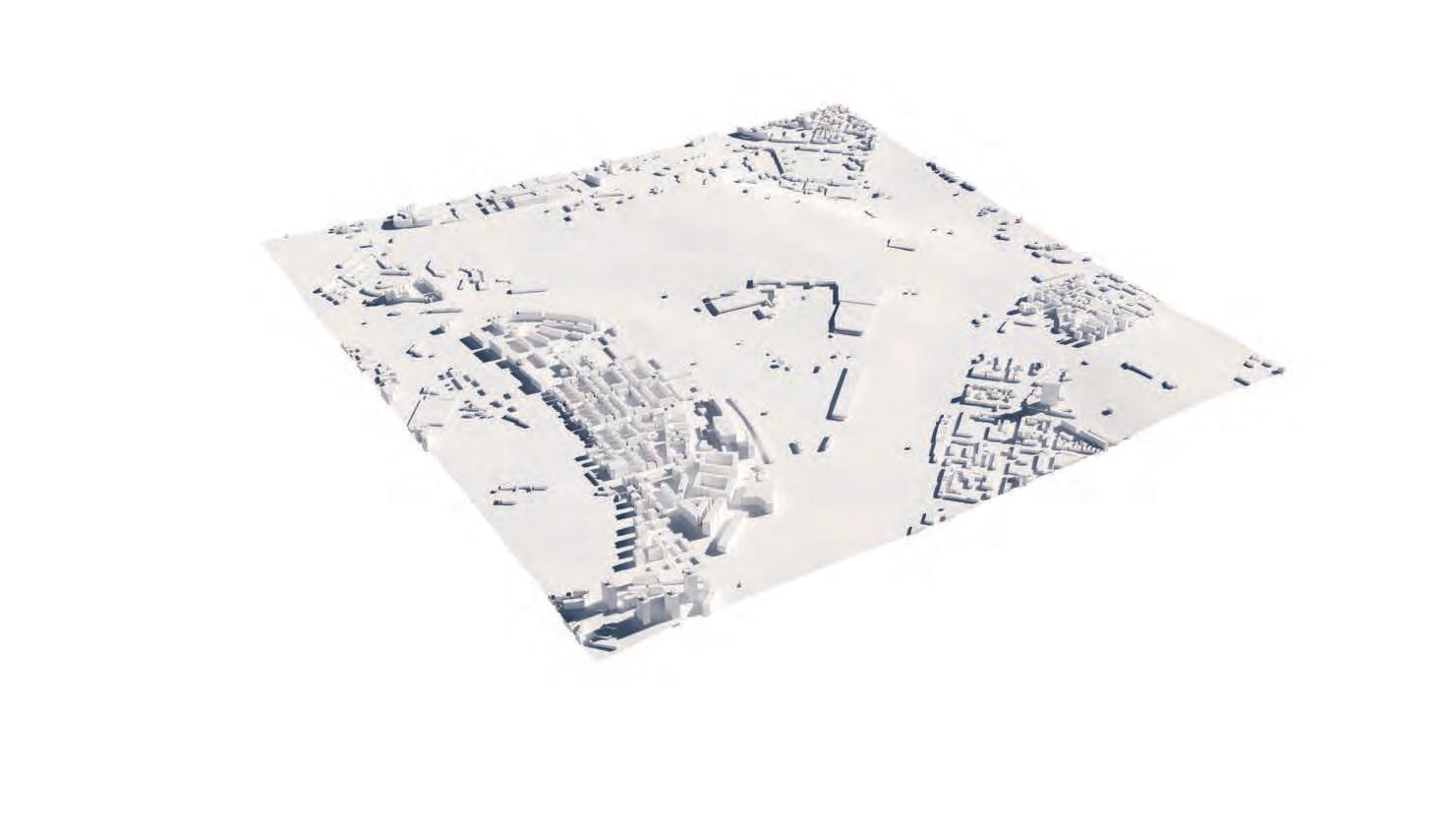
Rosensteinpark, Weissenhof and Neckar Valley
The site is located on a slope. There is a drop of 20 meters between the West and East end of the new Rosensteinpark development. This adds further design constraints. The neighbourhood adjacent to the site, Weissenhofsiedlung is mostly residential and allows for good views over the valley.
250 m250 m
Rosensteinpark
Site
Schlossgarten
Stuttgart Ost
Pragfriedhof
Stuttgart 21
Stuttgart 21 Killesberg
Killesberg
Pragfriedhof
Weissenhofsiedlung
Rosensteinpark
Weissenhofsiedlung
Neckar
Neckar
Green
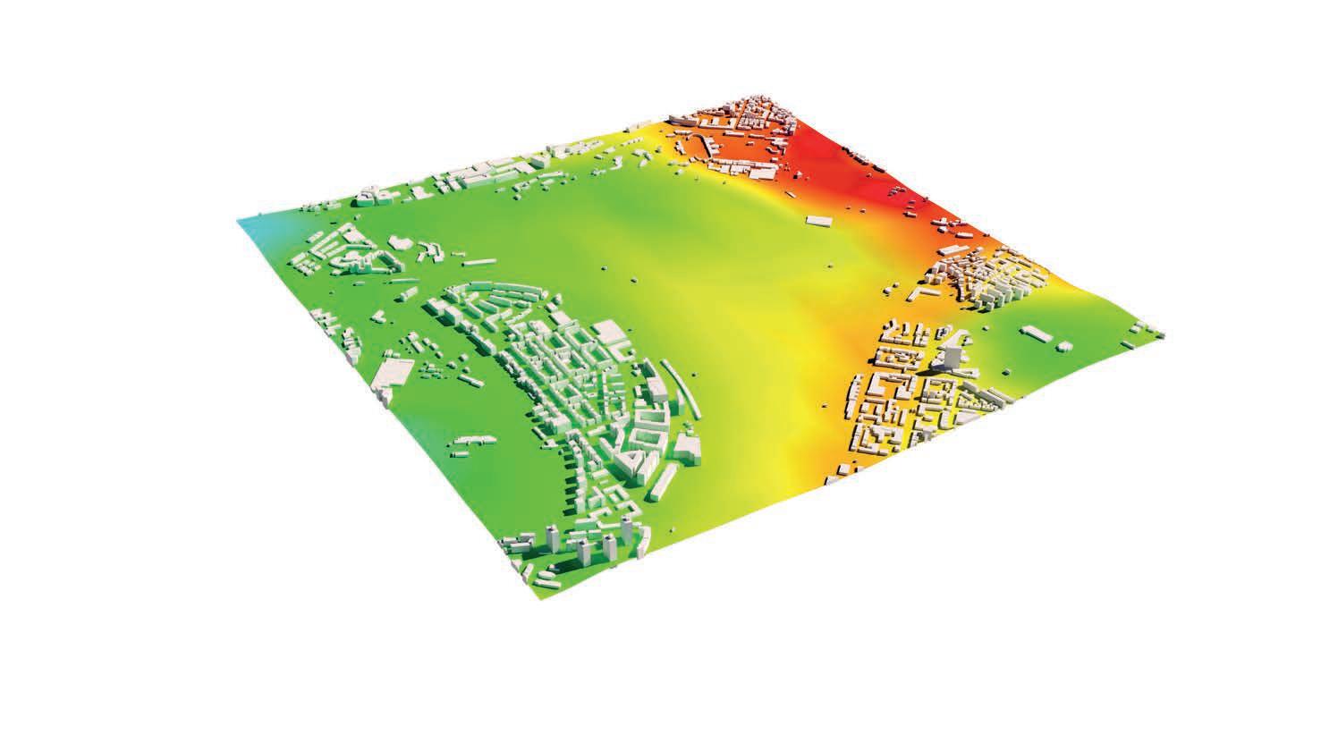
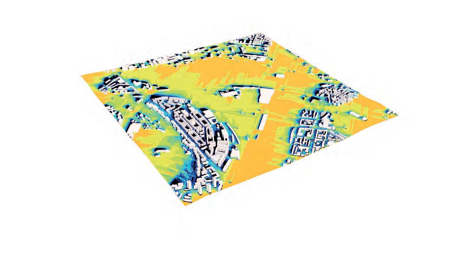
The site is adjacent to the Rosensteinpark Stuttgart NorthEast of Stuttgar’s city centre. Due to it’s location in a ‘Kessel’ bowl the city is dense and wind is funneled through the city with a primary wind direction of South-West. The open landscape gives the site lots of sun exposure. As part of the Stuttgart 21 redevelopment a new train connection is created at the North-Western edge of the site.
Mittnachtstr.
Pragfriedhof
Nordbahnhof
Löwentor
Eckart
Bibliothek
Metzstr.
Mineralbäder
Wilhelma
Rosensteinbrücke
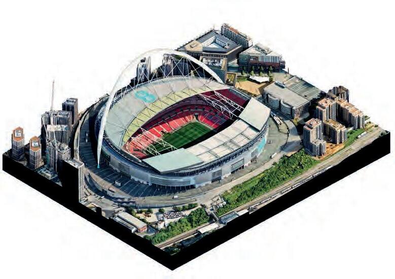
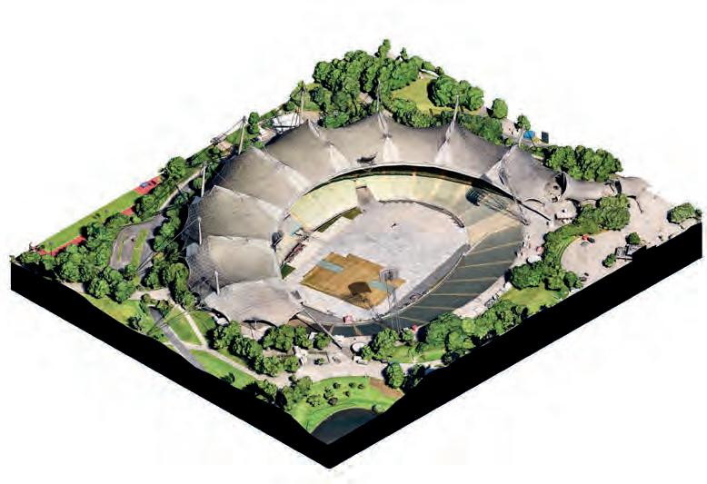
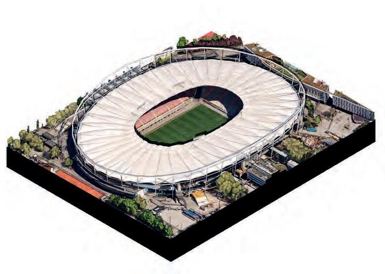
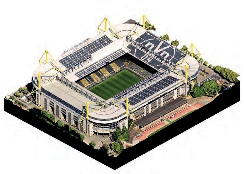
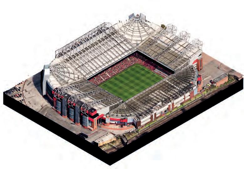
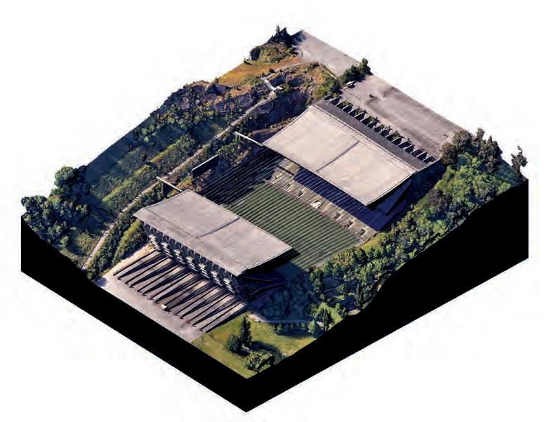
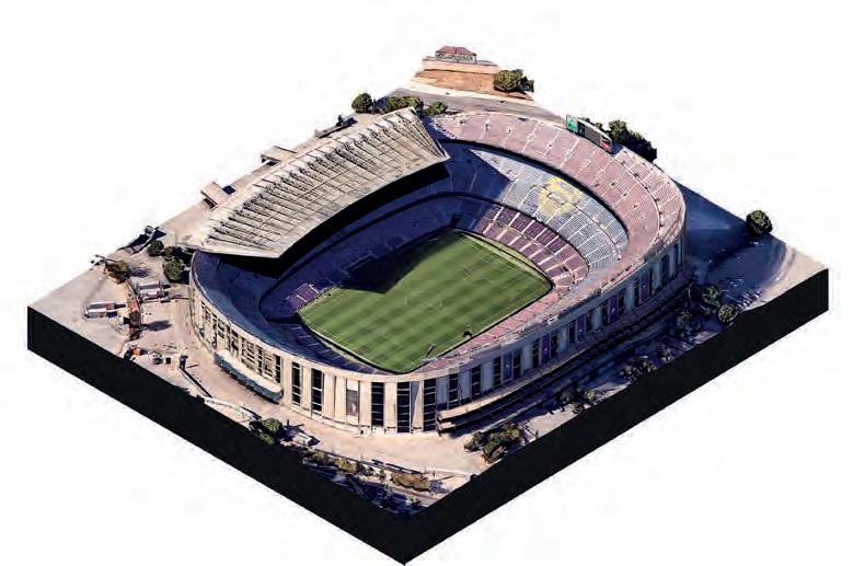
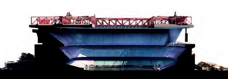
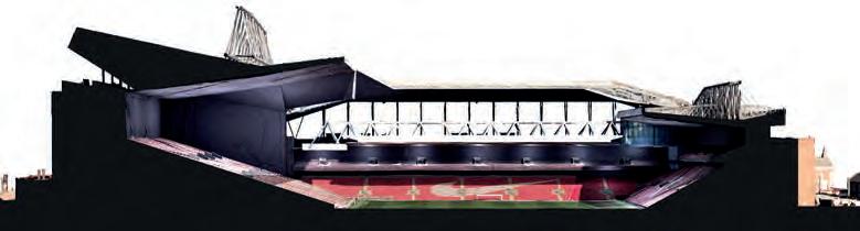
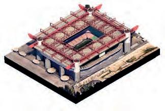
STADIA TYPOLOGIES
Westfalenstadion
Neckarstadion
Estádio Municipal de Btraga
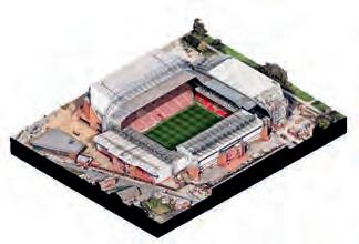
Old Trafford
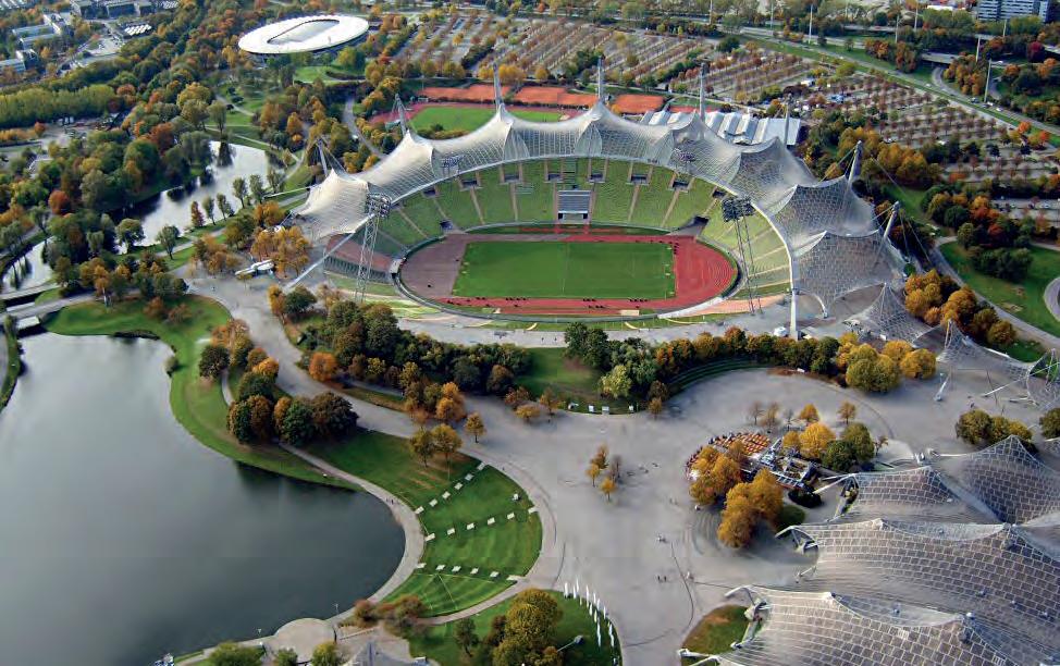
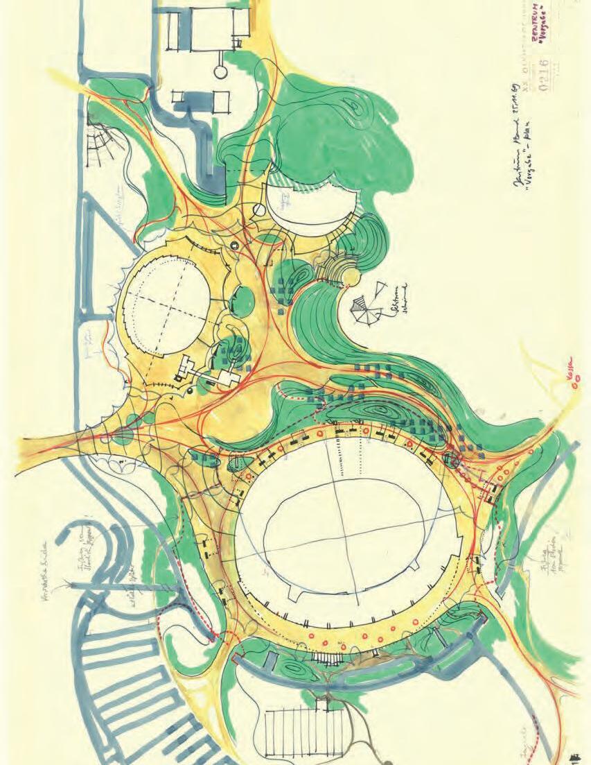
Olympic Stadium Munich
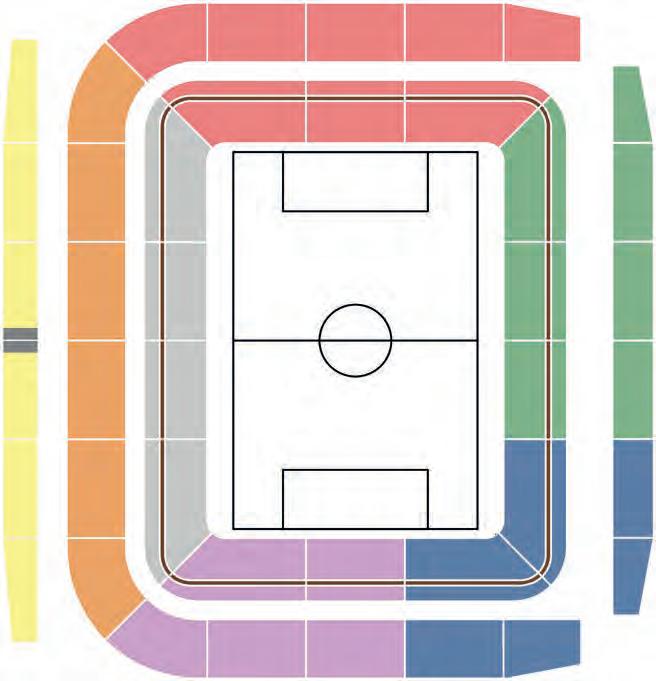
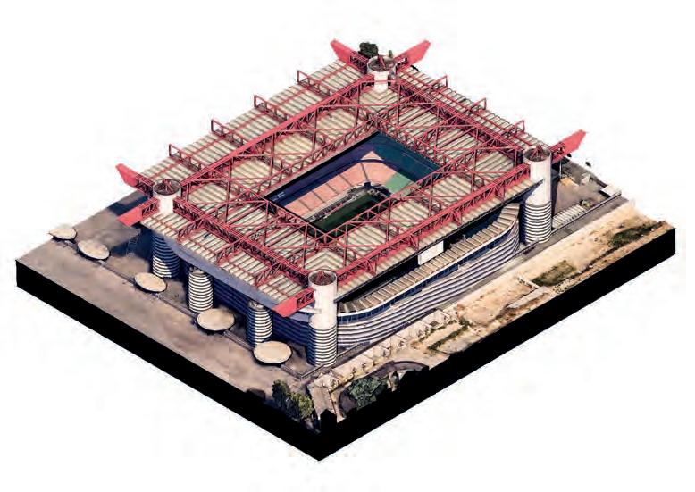
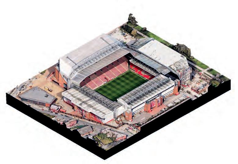
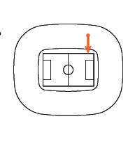
BOWL DESIGN
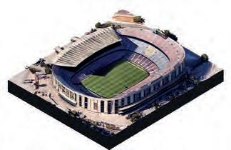
San Siro
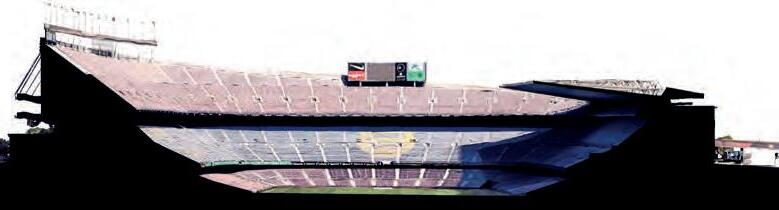
Camp Nou
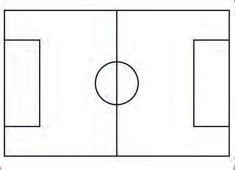
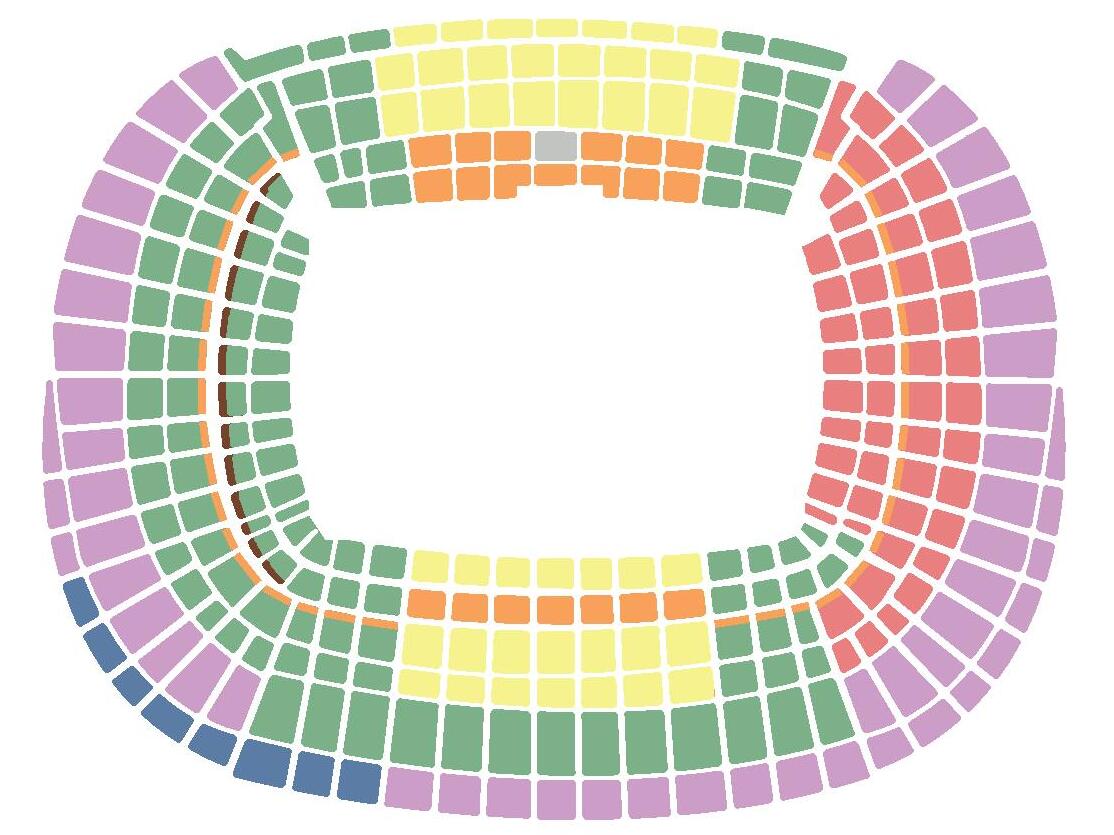
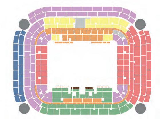
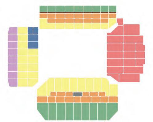
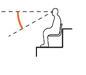
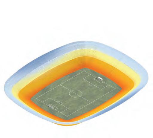
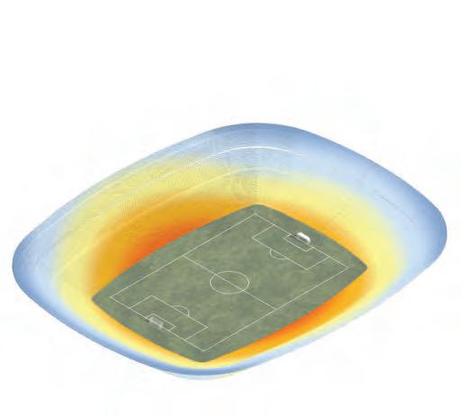
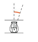
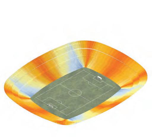
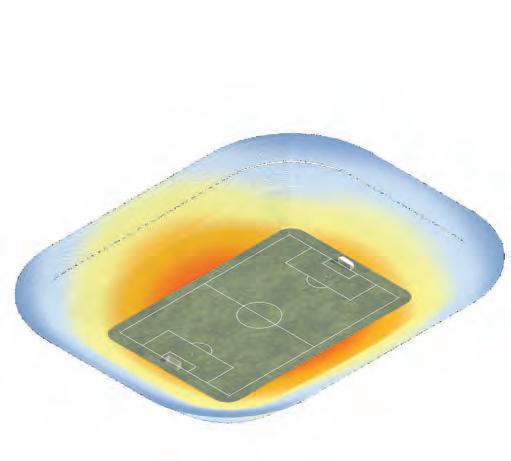
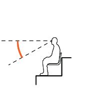
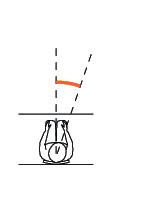
BOWL ANALYSIS
& ANGLES
VIEWS
Metrics for Bowl Design
San Siro
Camp Nou
Anfield Road
6 Options
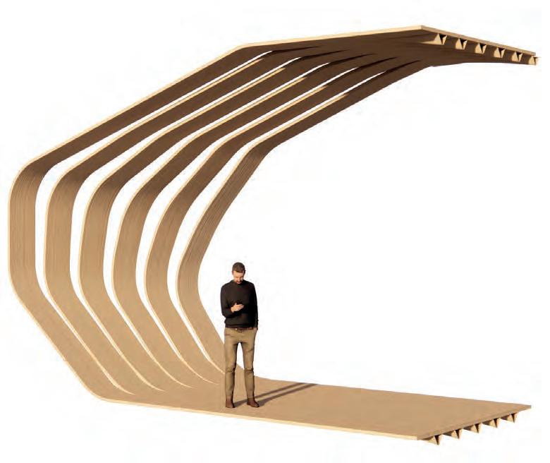
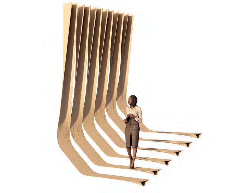
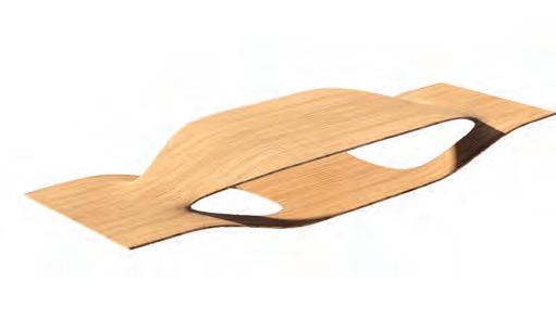
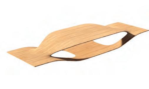
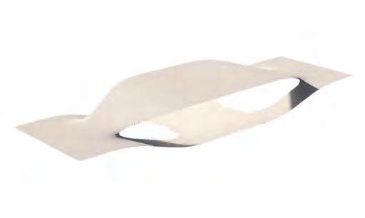
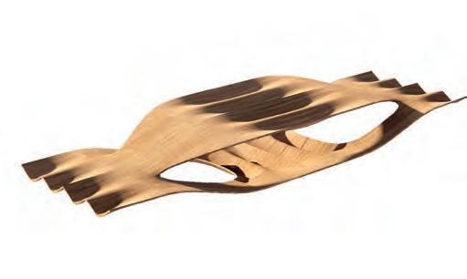
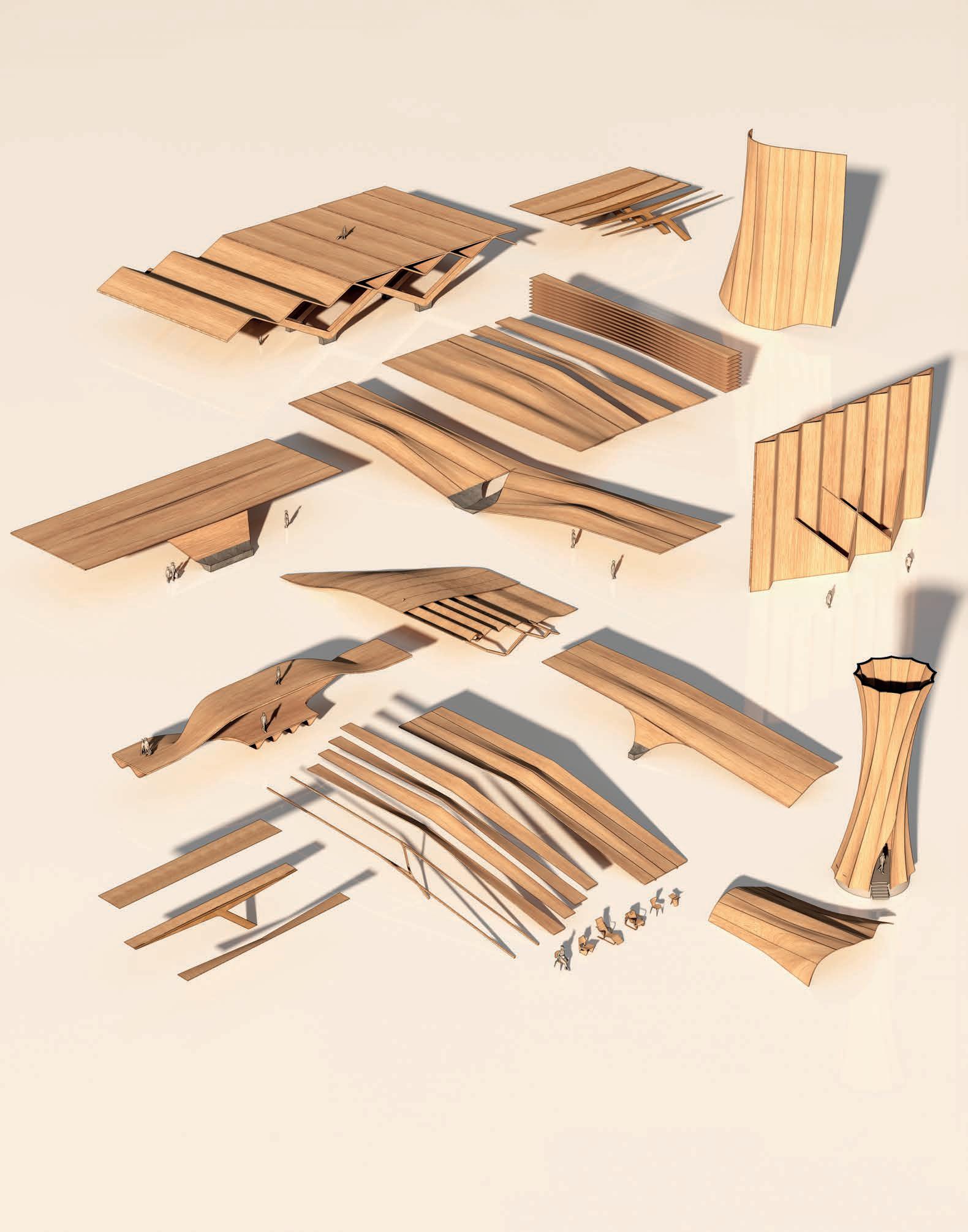
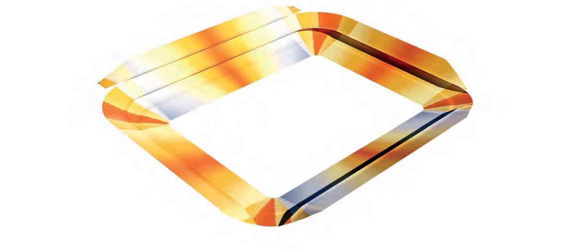
FRAGMENT ITERATIONS
BENDING WOOD EXPERIMENTS
Testing Structures
Throughout the design process different fragments have been tested. This image gives an overview over the most prominent iterations. They are based on the lamination strategy explored in furniture design or the Urbach Tower. All iterations use structural bending as a form of increasing strength.
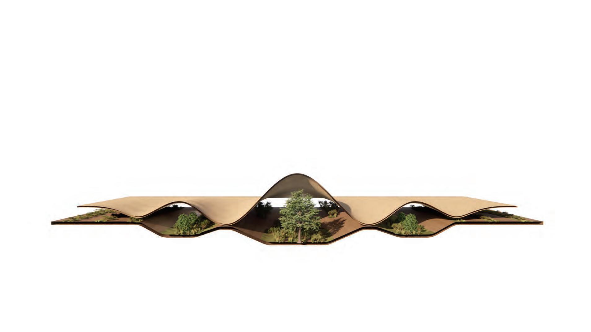
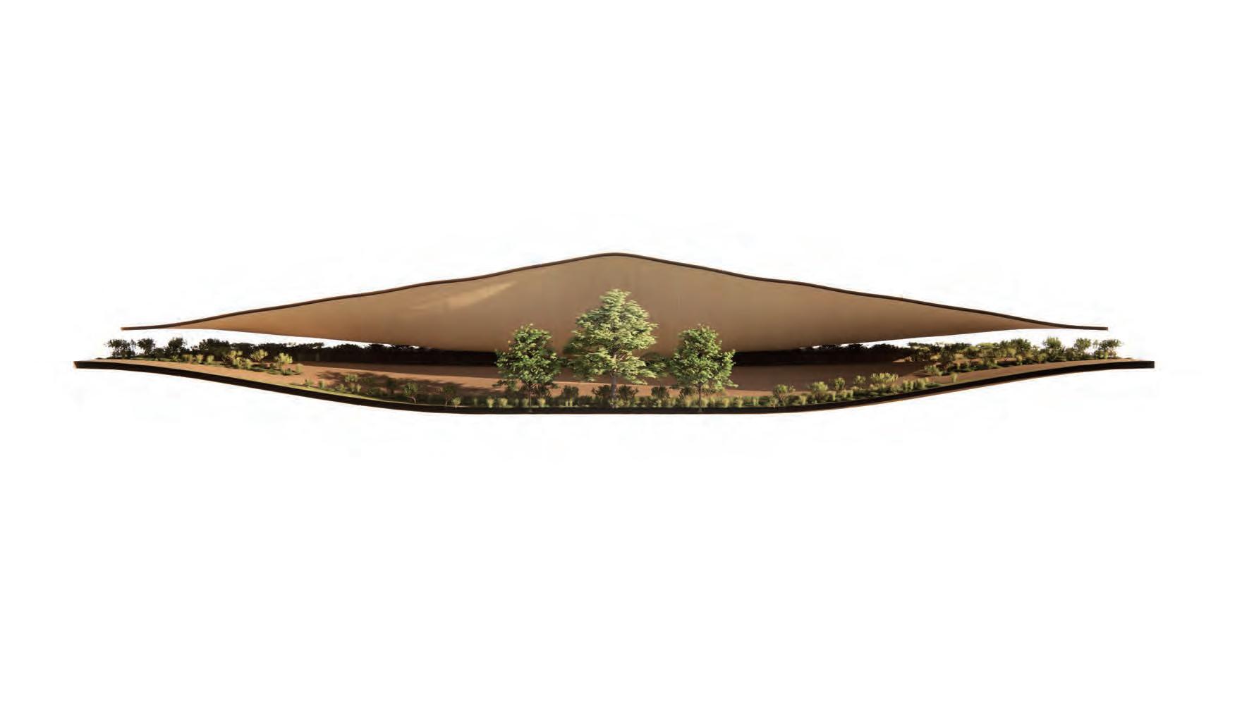
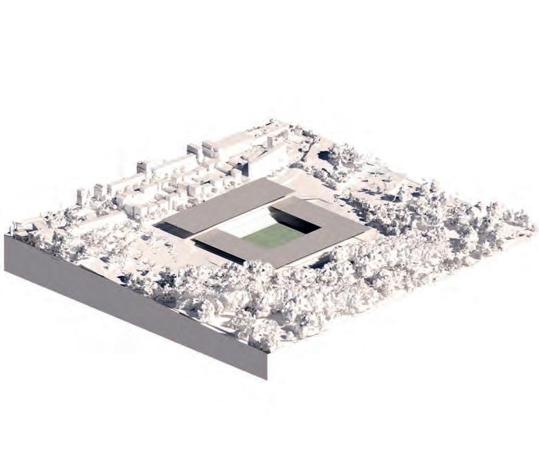
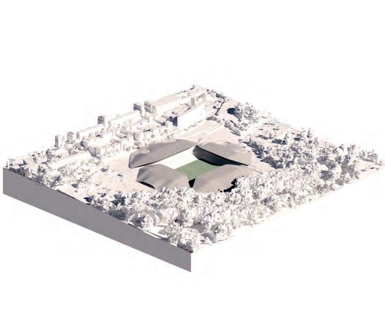
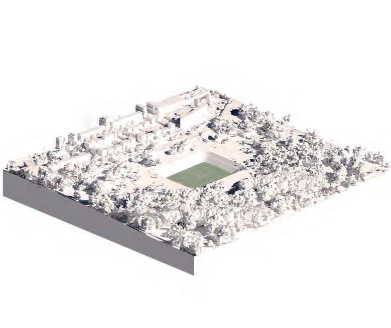
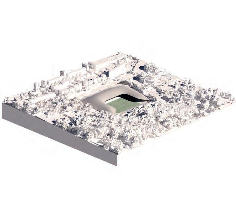
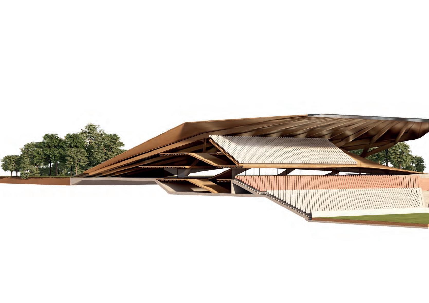
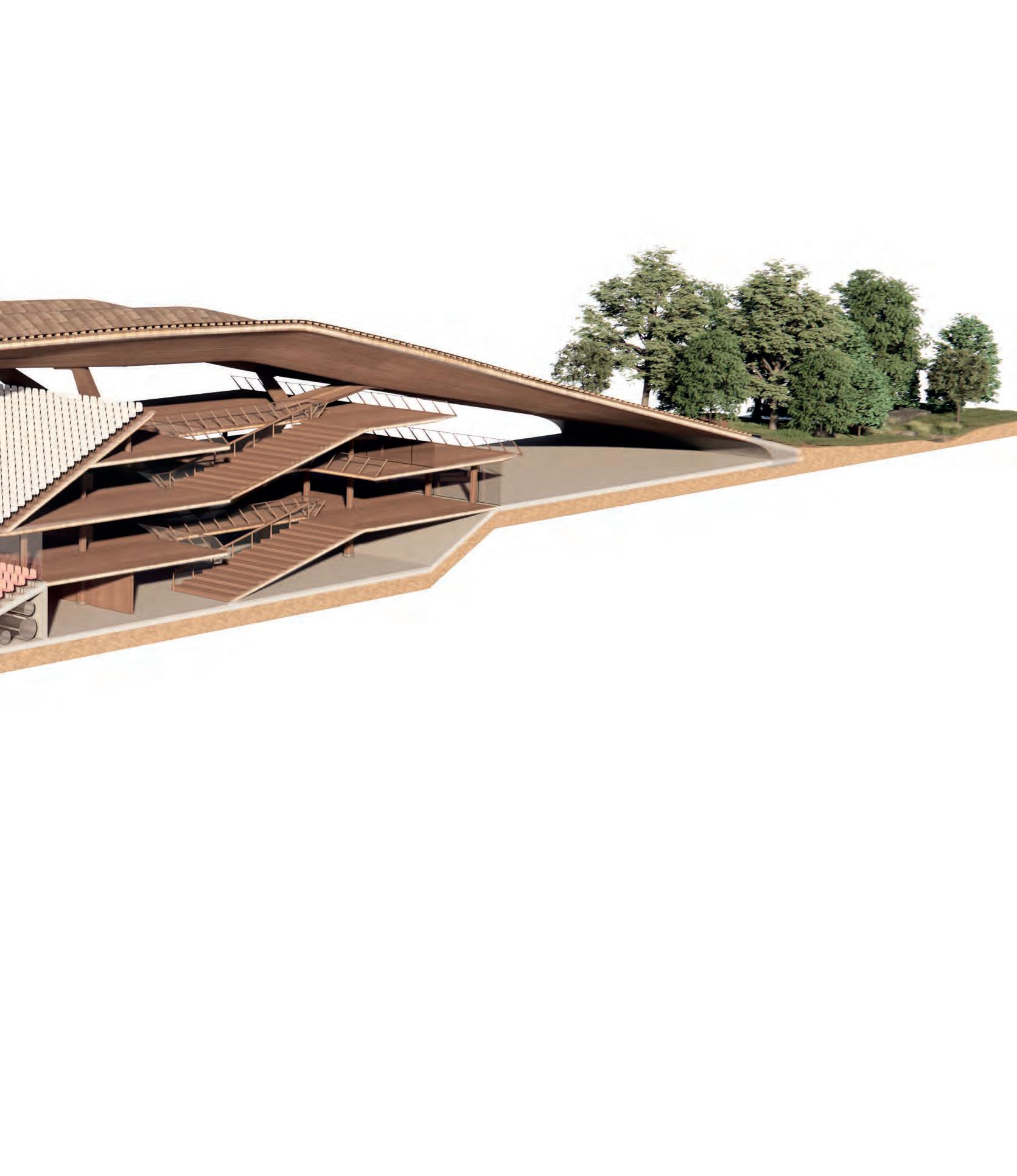
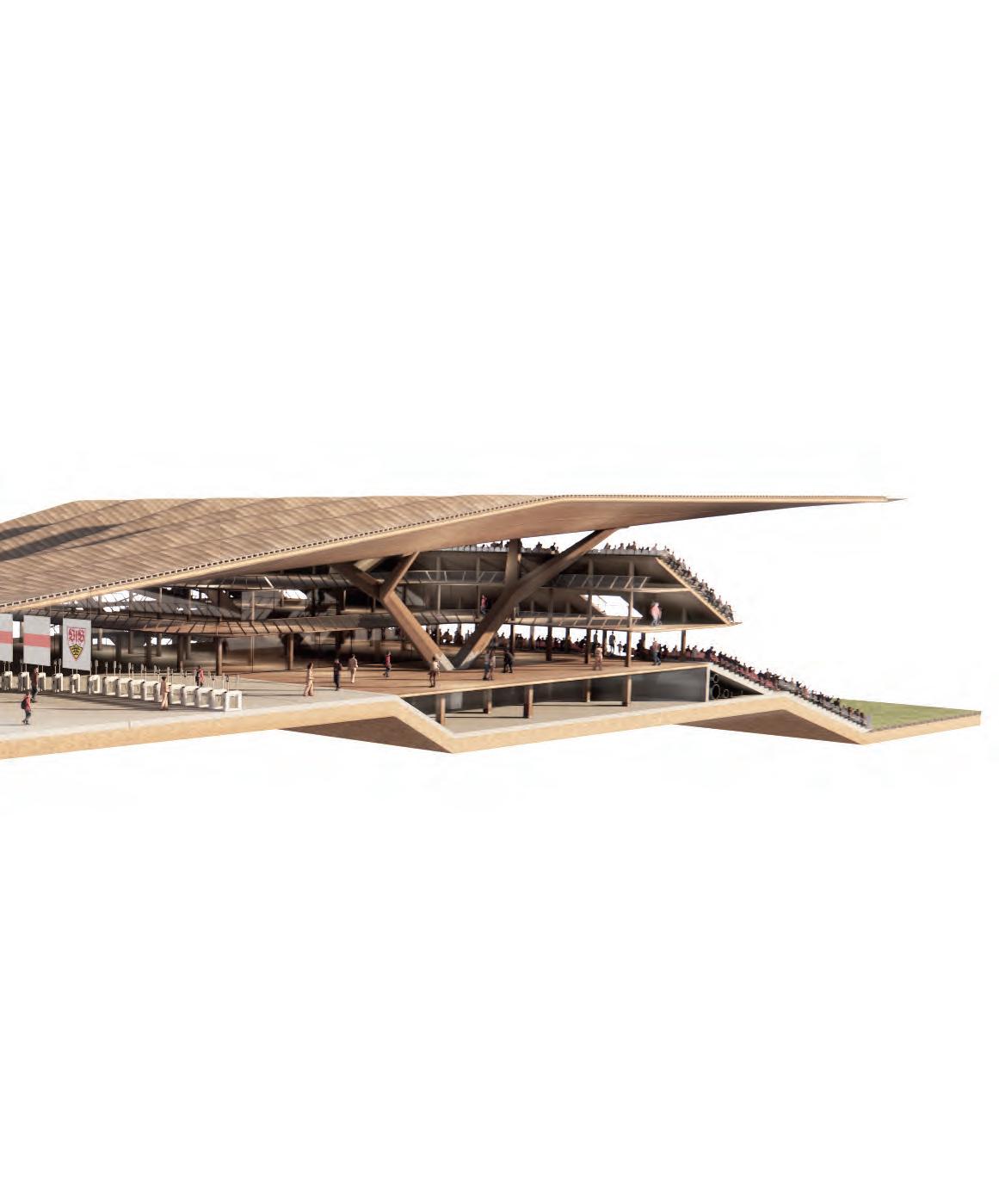
This is a study of different possible sections and roof configurations. The idea is that the roof drops down to the park in order to seamlessly integrated into the park. Towards the city it opens allowing a fluid transition. The sity side is larger due to an additional concourse and the train station.
SECTION STUDIES
ITERATION 1 to 4 Fragments
SECTION STUDY CITY
FRAGMENT
Pitch, Seating, Station & Community
The roof of this fragment follows the programmatic demands of the spaces beneath. The aim of this fragment is to create a city atrium for the stadium and also show how the train station can be set into the stadium.
CORNER STUDY
Roof
Shingles
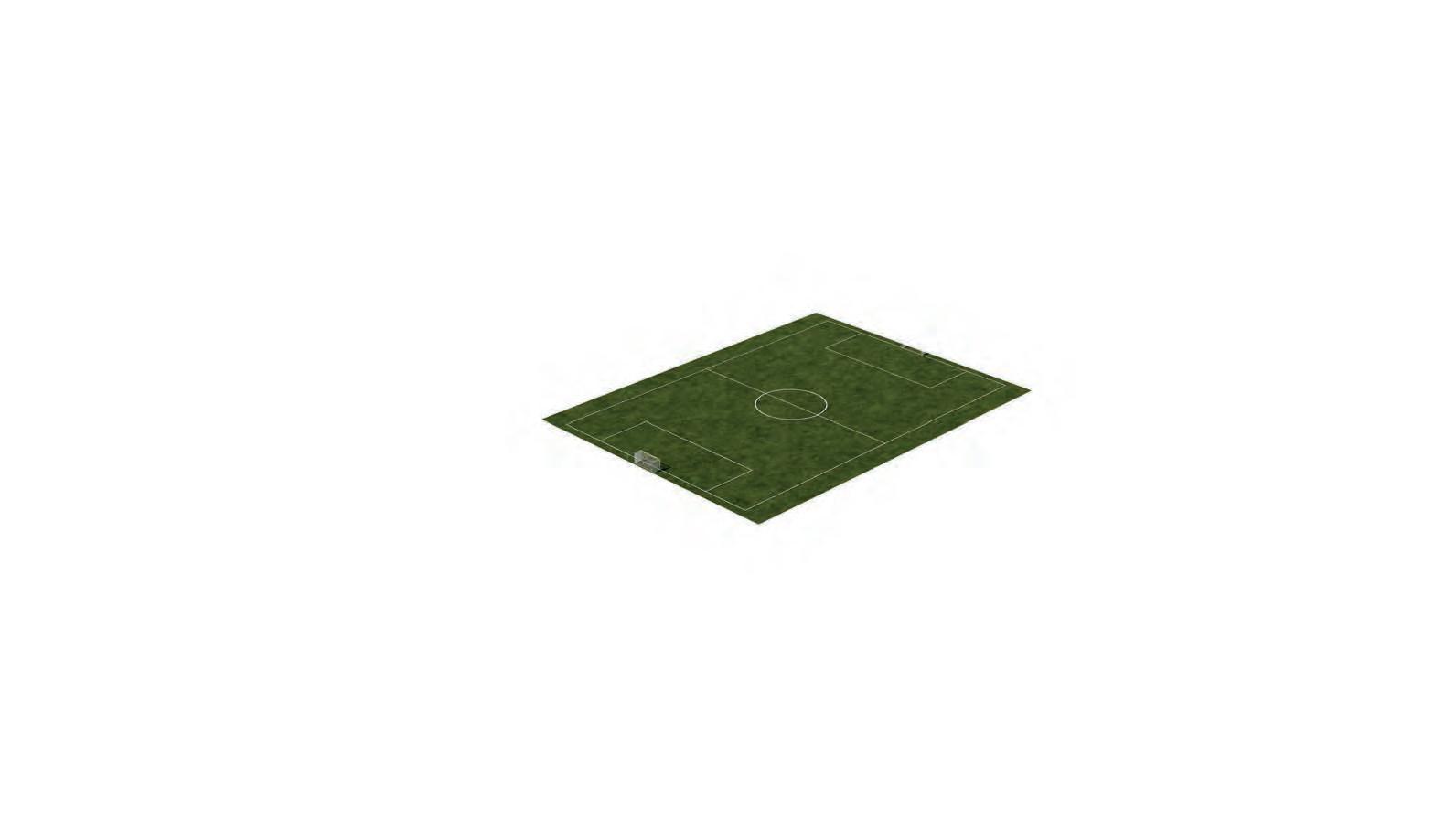
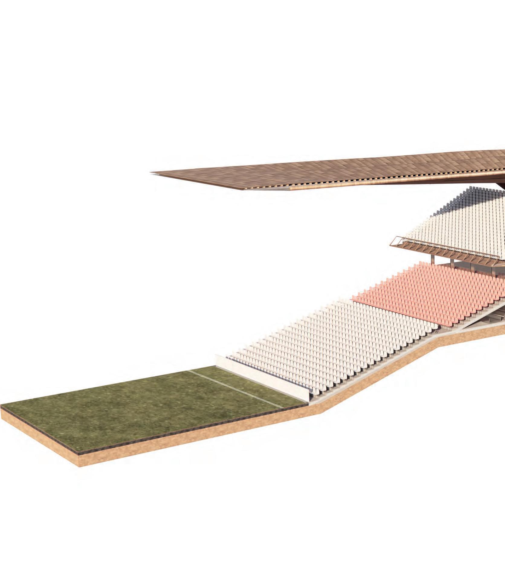
BOWL DESIGN
SEATING AND CONCOURSES
Optimizing Viewing experience
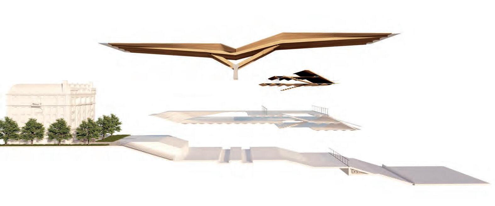
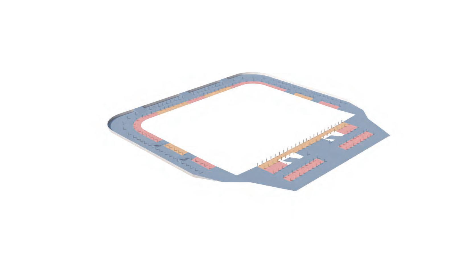
GENESIS DIAGRAM
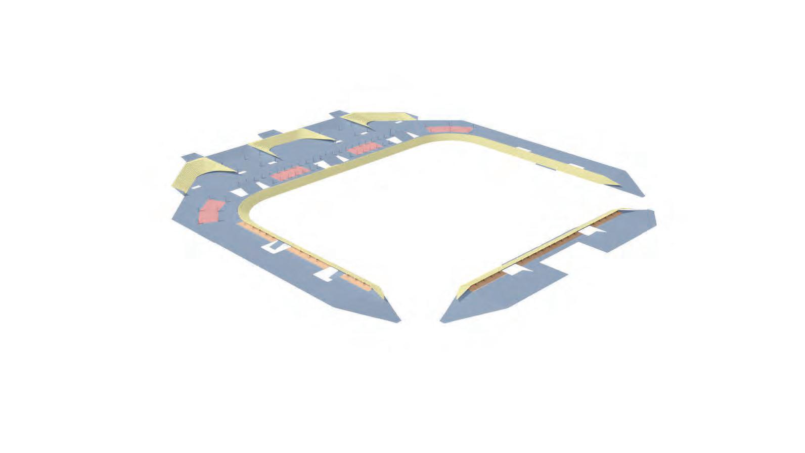
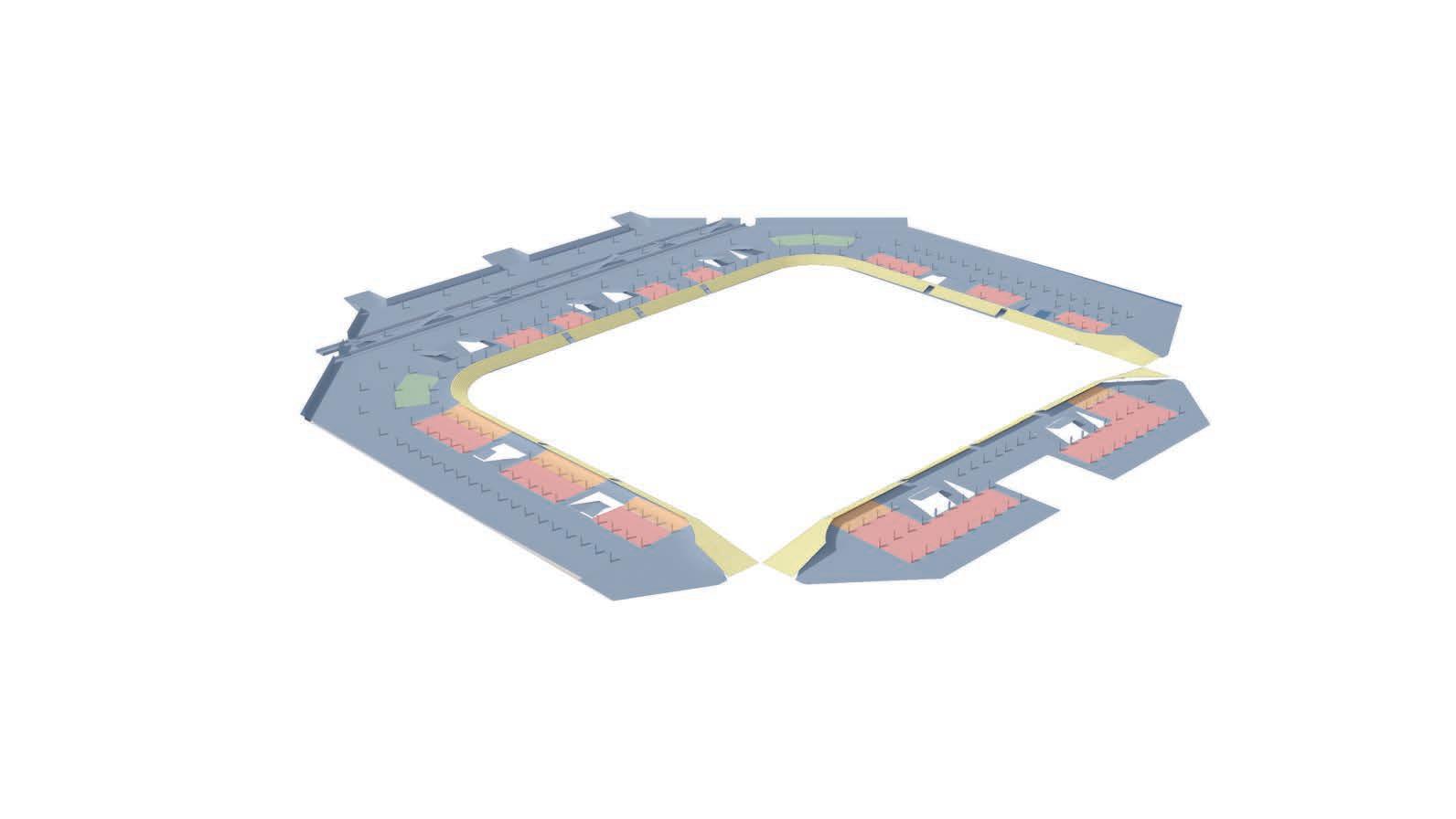
ACCESS & UTILIZATION
New Stadium Typology
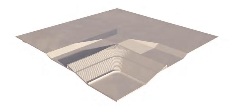
To reduce the footprint and the sizes of structural components of the building the site is dropped into the ground. It is located on a North-South axis which is standard for modern stadia design. Towards the city side the stadium is more open and spacious allowing for supporter gathering points. Within the concourses different types of hospitality are located.
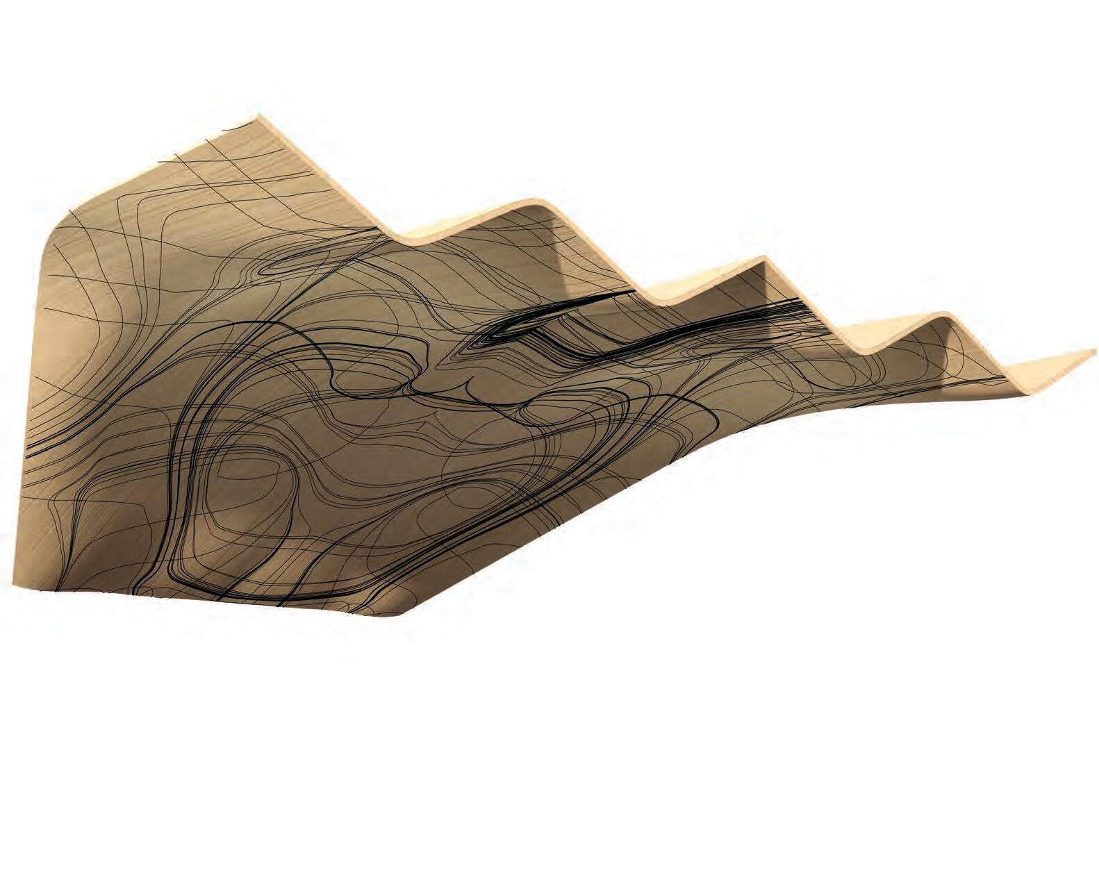
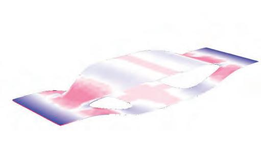
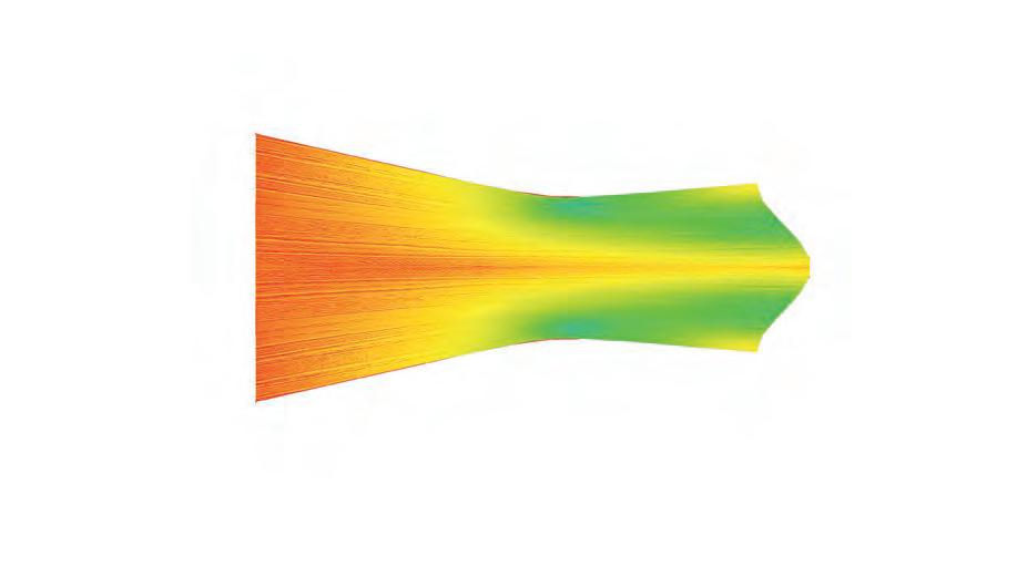
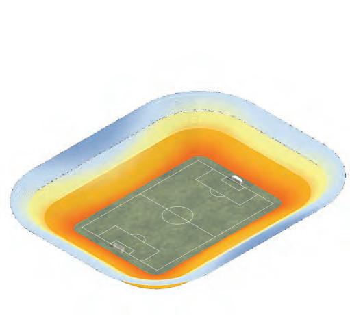
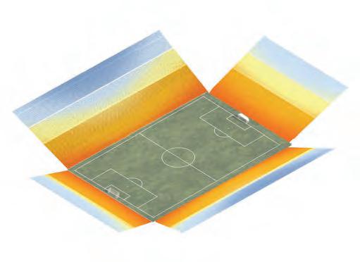
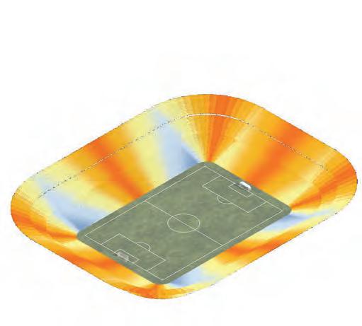
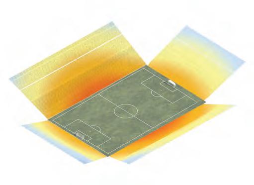
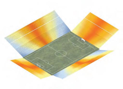
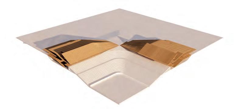
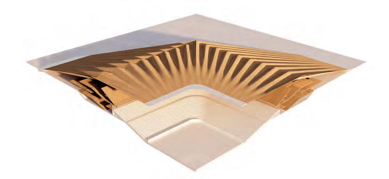
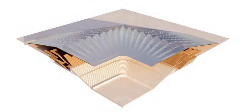
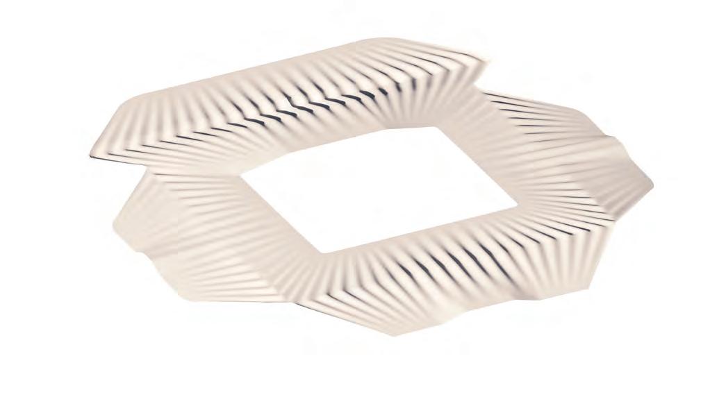
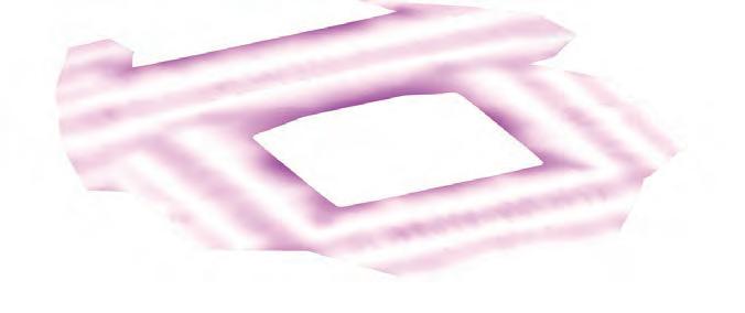
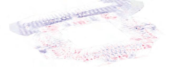
ROOF DESIGN STRUCTURAL OPTIMIZATION
Overview
These images give an overview on the structural performance of the roof. Due to the size of the model and many variables it is not clear how accurate the results are. Therefore in a next step the roof is subdivided into different sections, whereas each section is analysed individually.
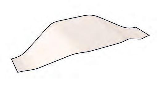
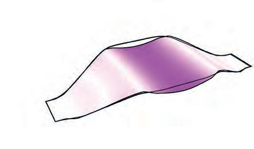
ROOF FORM FINDING GEOMETRY
RELAXATION
Workflow
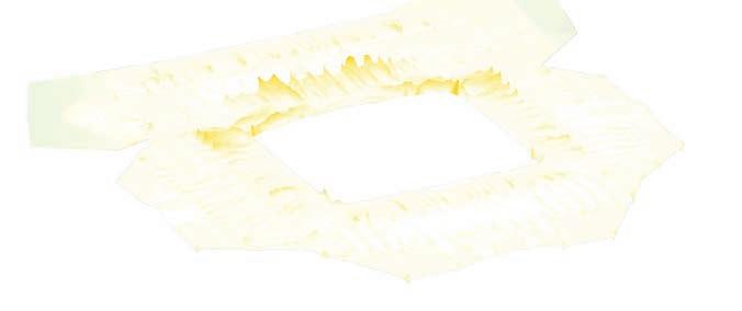
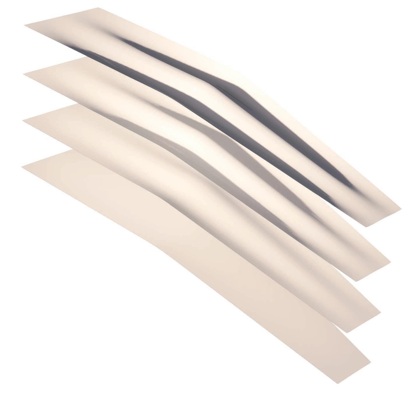
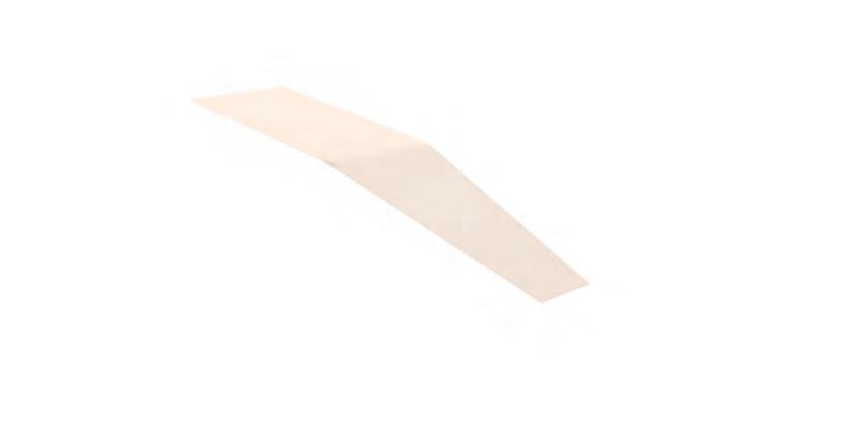
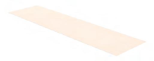
Geometry optimisation is carried out with the plug-in Kangaroo. This tool performs a relaxation process in which forces are redistributed across a mesh, iteratively smoothing and adjusting the form until a stable equilibrium is reached that reflects structural efficiency. The diagram demonstrates this process on a single roof cross-section, showing how the surface progressively bends from version 1 to 4.
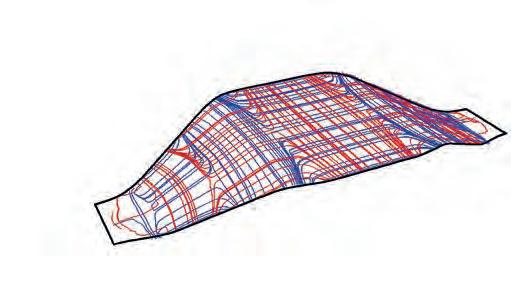
ROOF RATIONALIZATION
GEOMETRY RELAXATION
Karamba Optimization
The input surface is subdivided according to predefined panel sizes, with boundary edges A and B fixed. When subjected to a uniform distributed load (UDL), the geometry relaxes into an optimised curved form. Following this step, any remaining hard edges are curved for continuity. This process is calculated for 3 different geometries of the roof.
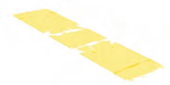
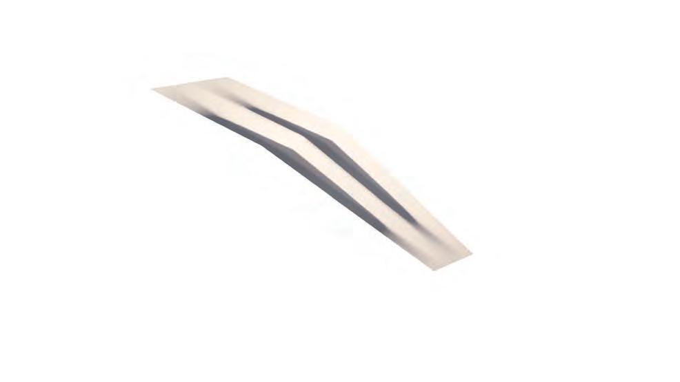
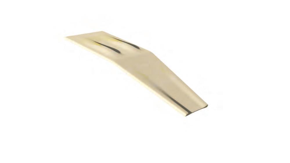
The diagrams show the performance improvement achieved with structural bending. The cross section is reduced significantly. This reduces the dead load which takes load of the support structure.
Hardwood
Hardwood
Hardwood Fragment
Hardwood Fragment
Thickness Optimization
Thickness
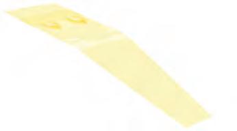
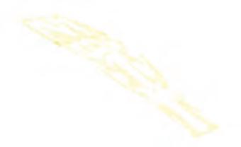
Principal Stress Lines
Principal Stress Lines
Geometry
Displacement
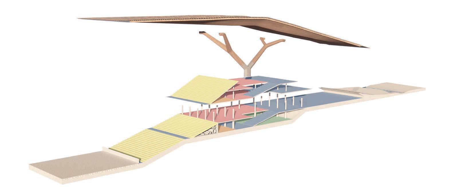
STRUCTURAL SYSTEM
SURFACE & SUPPORT STRUCTURE
Analysis
Half the timber panels are bent convex and the other half is concave. Supports connect to the concave panels. The support structure branches which reduces the foundation size and allows for bigger spaces under the roof.
& LAMINATION
Lamination thickness are optimized with Karamba 3d. The crossection uses a total of 17 x 20 mm laminates with 5 oak hardwood laminates sandwiching 7 fir softwood layers. The supports ‘plug’ into the roof structure.
Convex Panels
Concave Panels
SUPPORT STRUCTURE
SUPPORT STRUCTURE
The support system is arrayed along the roof. Due to the fixed connection between the different panels there is no need for additional stiffening.
Roof Section
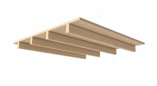
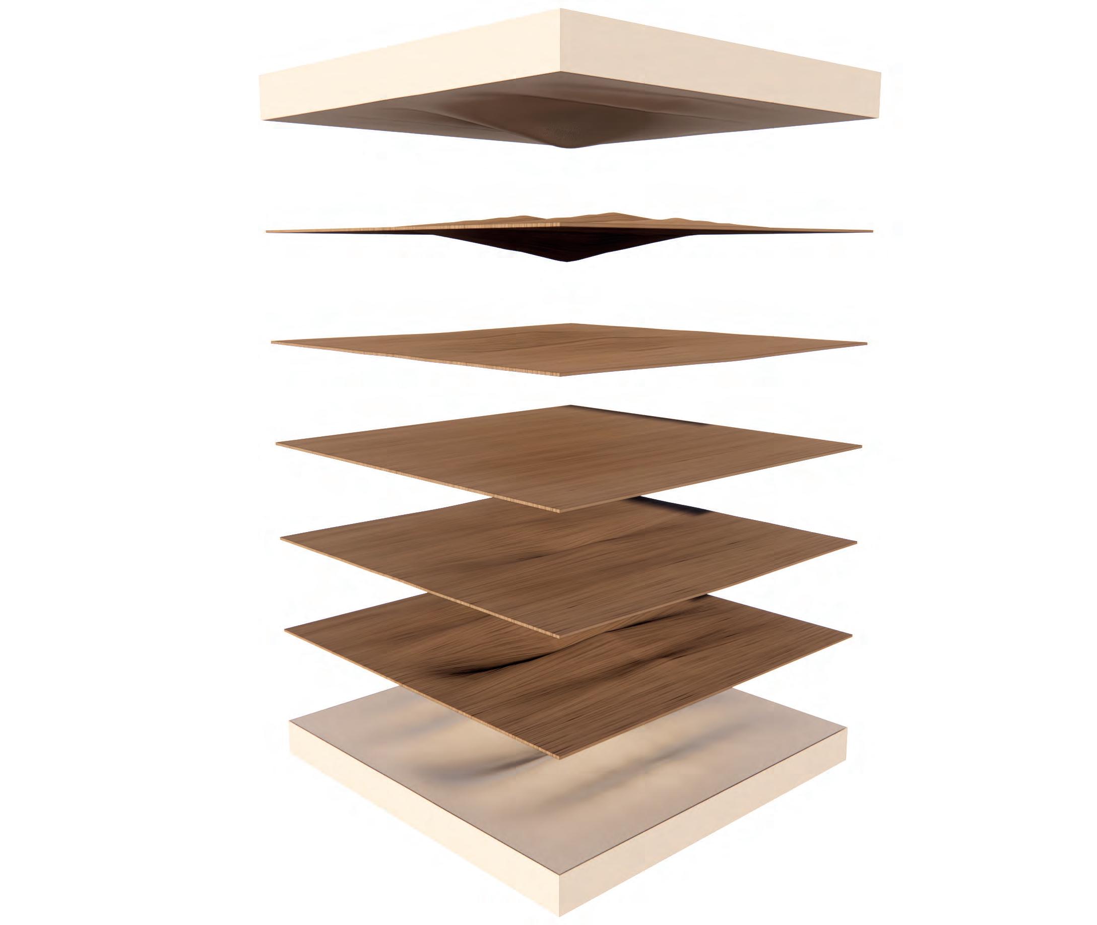
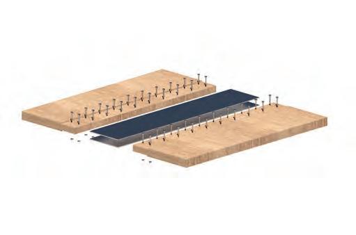
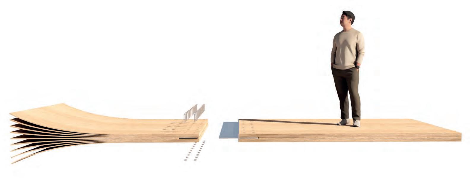
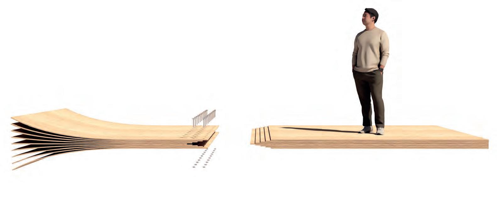
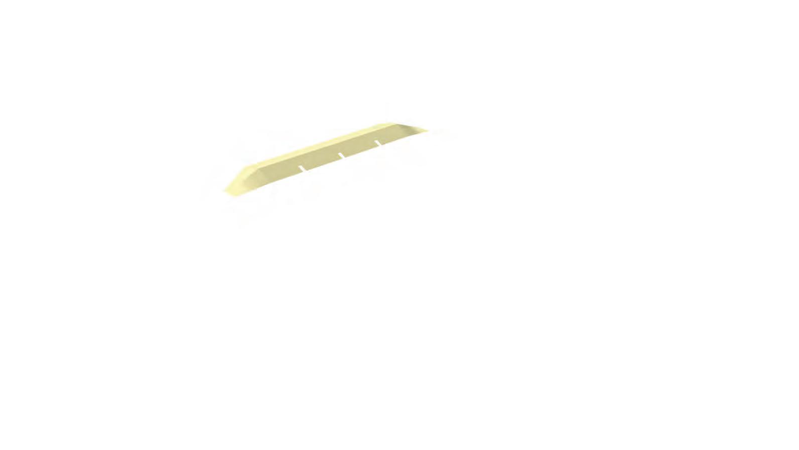
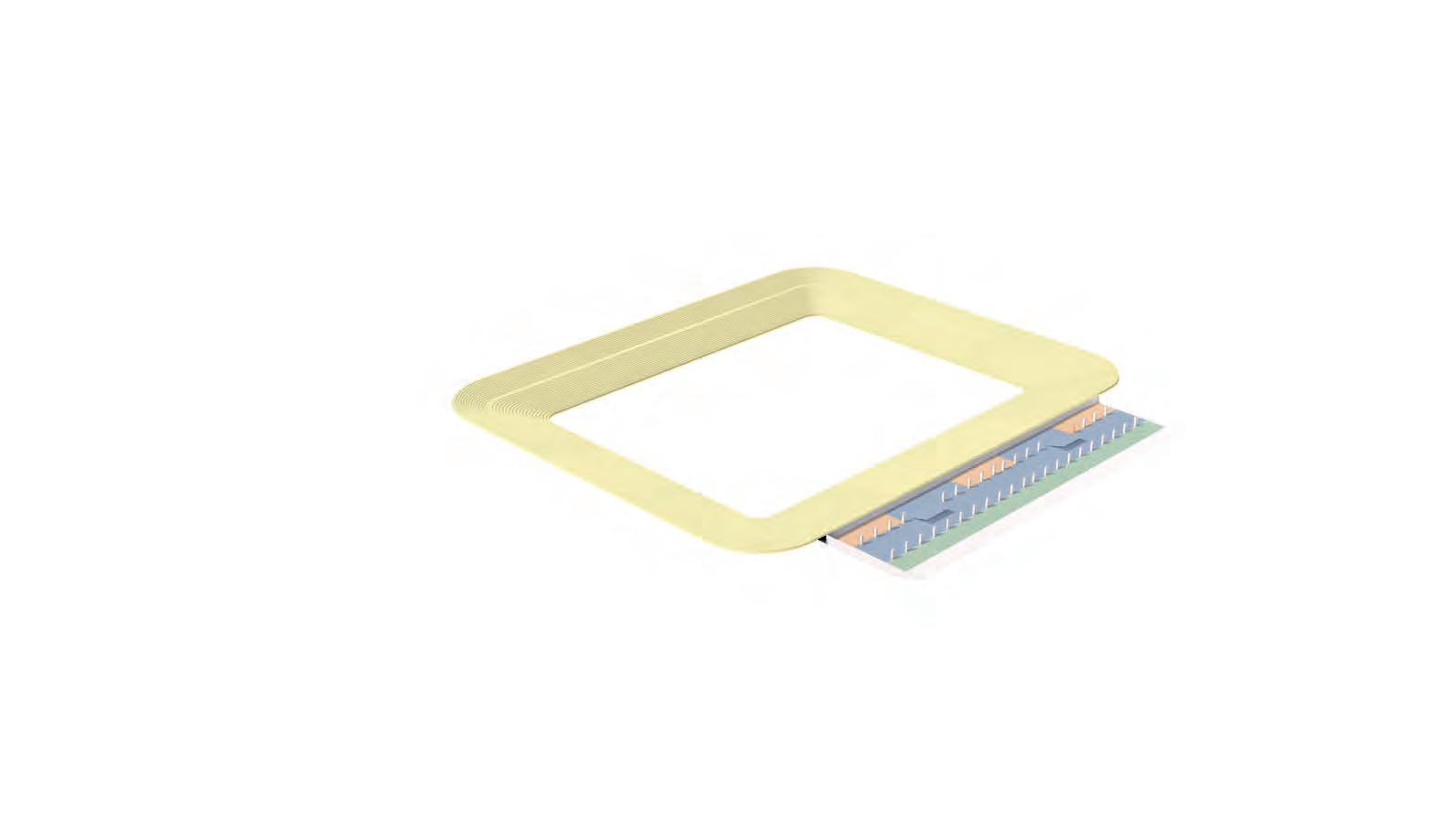
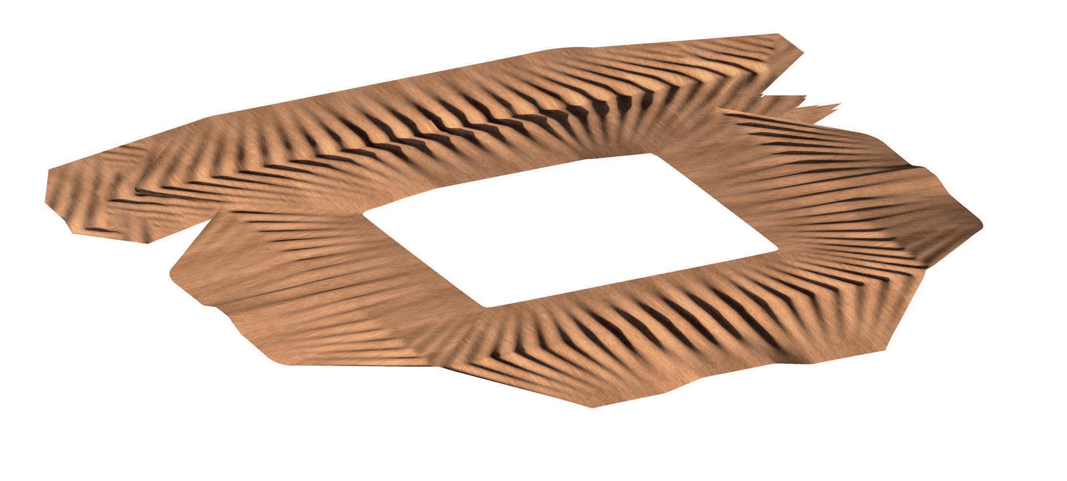
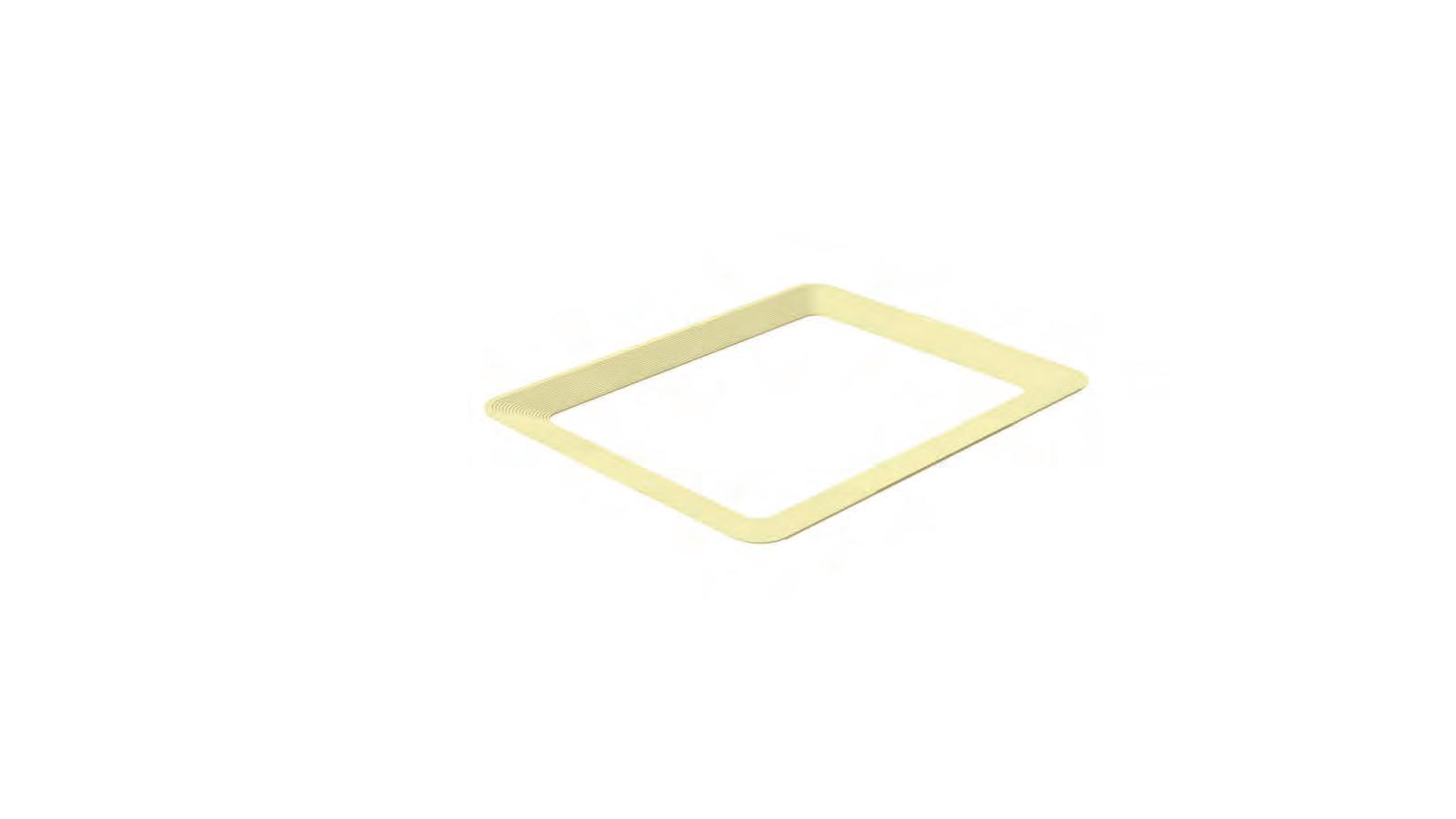
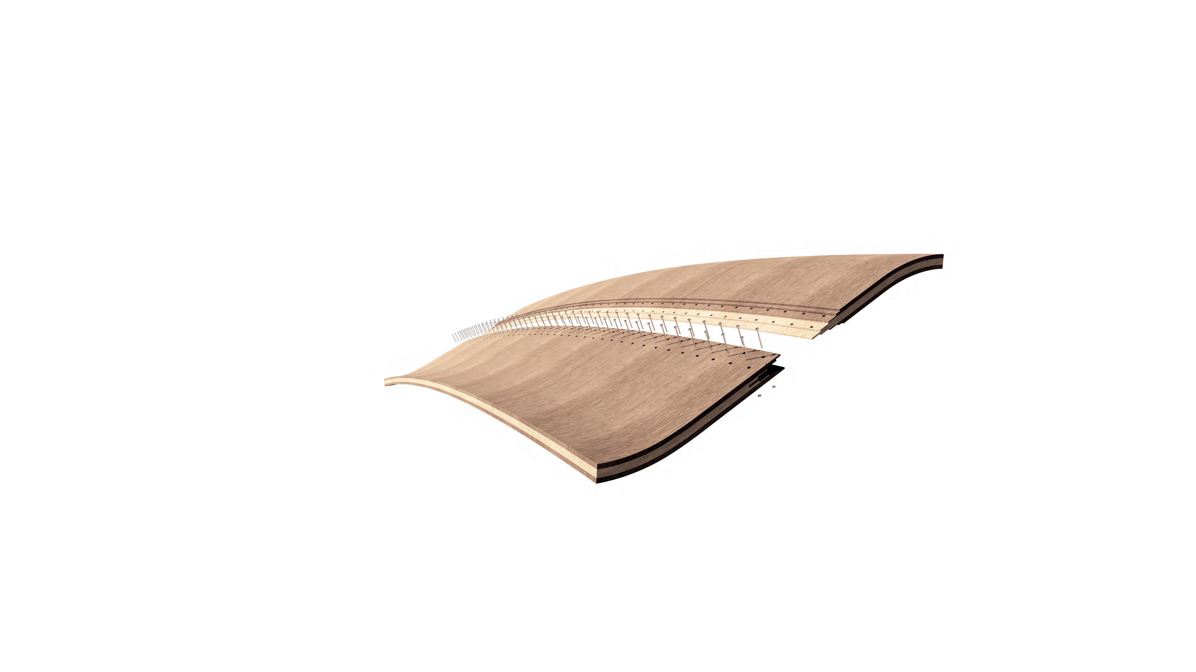
JOINERY DETAIL
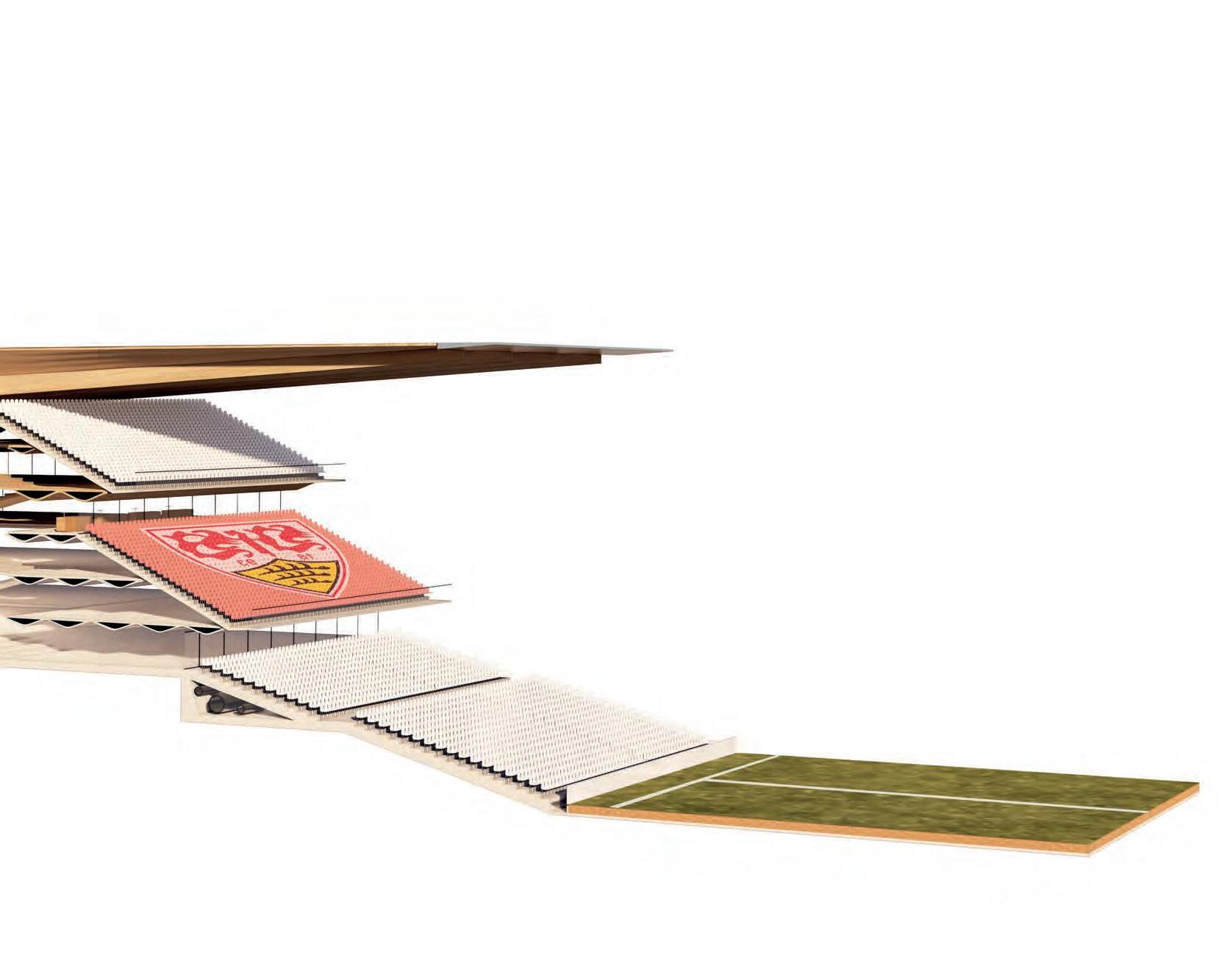
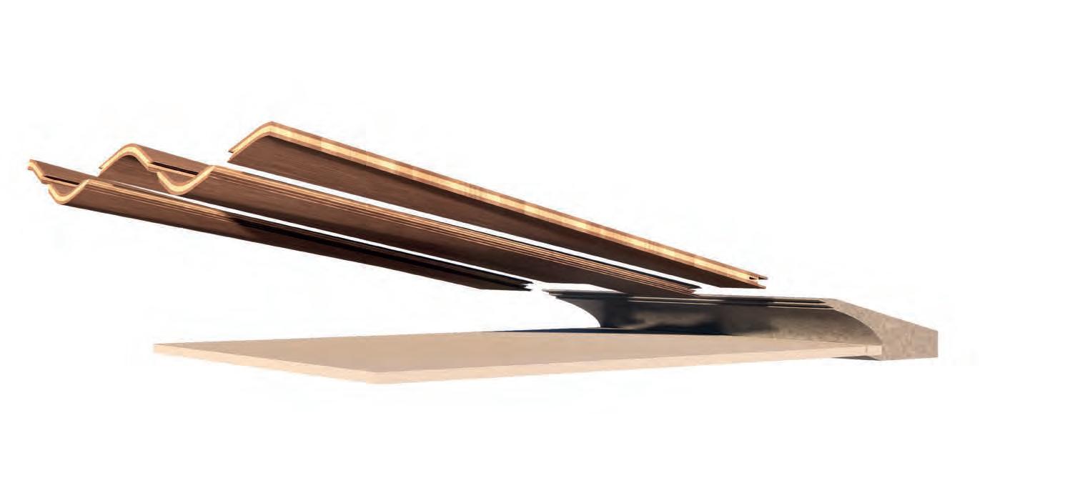
ROOF LAYERS
This detail shows the roof layers. including the waterproofing and weather protection. Slates sit on 50 mm timver joists. Each laminate panel is created with a set of smaller stitched laminates and then pressed together into the required form.
Laminate Roof
Concave Laminate
Convex Laminate
Joist
Shingles
All work produced by Unit 14
Cover design by Charlie Harrishttps://www.ucl.ac.uk/bartlett/architecture
Copyright 2025 The Bartlett School of Architecture, UCL All rights reserved.
No part of this publication may be reproduced or transmitted in any form or by any means, electronic or mechanical, including photocopy, recording or any information storage and retrieval system without permission in writing from the publisher.
INVESTIGAIVE DOMAIN 2025
At the center of Unit 14’s academic exploration lies Buckminster Fuller’s ideal of the ‘The Comprehensive Designer’, a master-builder that follows Renaissance principles and a holistic approach. Fuller referred to this ideal of the designer as somebody who is capable of comprehending the ‘integrateable significance’ of specialised findings and is able to realise and coordinate the commonwealth potentials of these discoveries while not disappearing into a career of expertise. Like Fuller, we are opportunists in search of new ideas and their benefits via architectural synthesis. As such Unit 14 is a test bed for exploration and innovation, examining the role of the architect in an environment of continuous change. We are in search of the new, leveraging technologies, workflows and modes of production seen in disciplines outside our own. We test ideas systematically by means of digital as well as physical drawings, models and prototypes. Our work evolves around technological speculation with a research-driven core, generating momentum through astute synthesis. Our propositions are ultimately made through the design of buildings and through the in-depth consideration of structural formation and tectonic. This, coupled with a strong research ethos, will generate new and unprecedented, one day viable and spectacular proposals. They will be beautiful because of their intelligence - extraordinary findings and the artful integration of those into architecture.
The focus of this year’s work evolves around the intrinsic chance and professional desire for creative and systematic investigation. The explorative and intellectual process of iterative learning through informed experiment, catalysed by potent discoveries and ultimately seeking an architectural application. An intensely investigative approach enables the architect’s fundamental agency and core competency of the profession to anticipate the future as the result of the highest degree of synthesis of the observed underlying principles underpinned by strong research. Constructional logic, spatial innovation, typological organisation, environmental and structural performance are all negotiated in a highly iterative process driven by intense architectural investigation. Through the deep understanding of principles, we will generate highly developed architectural systems of unencountered intensity where spatial organisation arises as a result of sets of mutual interactions. Observation as well as re-examination of past and contemporary civilisational developments will enable us to project near future scenarios and position ourselves as avant-garde in the process of designing a comprehensive vision for the forthcoming. The projects will take shape as research based, imaginative architectural visions driven by speculation.