Archie Koe_Y4 | Unit 14 | Bartlett School of Architecture
THE HYPÆR DERBY
ARCHIE KOEYEAR 4
All work produced by Unit 14 Cover design by Charlie Harris
https://www.ucl.ac.uk/bartlett/architecture
Copyright 2025 The Bartlett School of Architecture, UCL All rights reserved.
No part of this publication may be reproduced or transmitted in any form or by any means, electronic or mechanical, including photocopy, recording or any information storage and retrieval system without permission in writing from the publisher.
@unit14_ucl
archiekoe@gmail.com @archi.e.tecture
THE HYPÆR DERBY
A HORSE RACING STADIUM WITH INNER PADDOCK AND OUTER RACETRACK
Salisbury, UK
The Hypær Derby reimagines racetrack architecture through hyperbolic paraboloid (Hypar) surfaces that unify structure and spectacle on the outskirts of Salisbury. This floating timber roof serves as both shelter to the grandstand beneath and occupied stage for viewing and betting, with its saddle-shaped geometry enhancing views while optimizing urban flow. The design features dual viewing experiences – exterior track observation and interior paddock viewing – all contained in one architectural system.
Structurally, the roof exploits hypar geometry to create a self-supporting torsion box ‘monocoque’ that floats above concrete grandstands, providing cantilevered protection and VIP elevated viewing experiences. Sustainable systems include on-site timber cultivation for carbon-negative construction and River Bourneintegrated storm water management for natural cooling. Piezoelectric seating harvests crowd energy, contributing to net-zero operations. Aerodynamically, the floating roof acted as a wing which induced vertically loading which required careful consideration for both the foundation connection and the live-load capacity.
Beyond racing, the venue adapts into a concert hall and gallery, offering year-round community value. By replacing traditional horse racing with mechanical competitors, the project addresses ethical concerns while maintaining sporting excitement. Creating immersive spectator engagement was crucial to gain competitive advantage and establish a market. The design
demonstrates how a stadium can reconcile entertainment, ecology, and technology— establishing a new model for future-focused sports venues.
THE HYPÆR DERBY
DESIGN RESEARCH
Energy Recovery System
Design Research
Concept Development
The artefact selected to address the ‘Investigative Domain’ brief was a trebuchet. Understanding the dynamic forces that act through the wooden structure of a trebuchet provides valuable insights for the design of systems intended to launch projectiles. Of particular interest was the energy recovery mechanism employed in some trebuchet designs, wherein the energy released during the firing process is partially captured and utilized to assist in rewinding the trebuchet arm for the next launch cycle.
Energy Recovery System - Non-fired State
Energy has not yet been harvested from the firing process, and the trebuchet’s mechanical system remains in an unfired state.
Energy Recovery System - Fired State
Energy is harvested from the firing process after release of projectile, harvested energy is used to wind the rope and recover energy.
The Optimisation of the Bow
Design Research
Concept Development
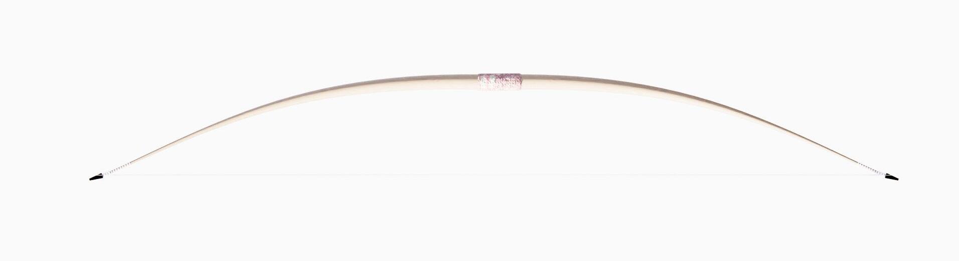
After studying the trebuchet’s mechanics, I began exploring how projectile-launching systems evolved— from longbows to crossbows. This led me to examine how wood selection and design changed over time to better withstand varying force loads, demonstrating improvements in material use, structural optimisation, and understanding of dynamic force distribution in weaponry.
LONGBOW
Development of Tensile Architectural System
Design Research
Concept Development
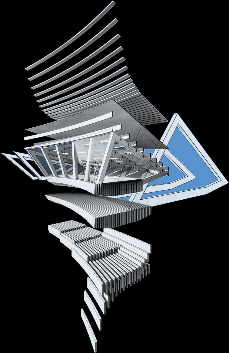
Studying the mechanics of the trebuchet and the optimized flex of a bow revealed how tension and compression shape dynamic force paths through wooden sytsems. This informed an architectural system that echoes these principles—balancing opposing forces through curved geometries—ultimately leading to a hyperbolic structural language.
Surface Typology of Hyperbolic Parabaloids
Design Research
Concept Development
Anticlastic (Hypar)
This project began by exploring hyperbolic paraboloids (hypars) as surface-driven urban flow applications, leveraging their anticlastic geometry to mediate interstitial boundaries between interior/ exterior spaces.
Hyperbolic paraboloids (hypars) are inherently anticlastic, meaning their orthogonal curves bend in opposite directions (one convex, one concave), creating a saddle-like surface with negative Gaussian curvature. This geometry efficiently channels tension and compression along distinct stress trajectories.
Synclastic surfaces, by contrast, curve in the same direction (e.g., domes), exhibiting positive Gaussian curvature and resisting loads through uniform compression.
Accessibility, Interstitial Boudnaries and Urban Flow
The variable angle of the edges of a hyperbolic parabaloid have architectural application for accesibility, intersitital boundaries and enhancing urban flow.
Accessibility
Application as Variable Angle Staircase
Interstitial Boundaries
Application as threshold between internal and external sapces, with multiple points of access.
Urban Flow
Application as interface between traffic and pedestrian crossing.
Hyperbolic Paraboloid (Hypar) Surface Formation and Advantages
Design Research Concept Development
Hyperbolic paraboloid (hypar) surfaces offer exceptional structural performance through their doubly curved geometry. The anticlastic shape naturally channels compressive and tensile forces along opposing curvatures, creating an efficient load path that minimizes bending stresses. This inherent stiffness provides excellent torsional resistance without requiring additional bracing.
Two Key Surface Topology Advantages
Tension along upward-curving parabolas. Compression along downward-curving parabolas
Existing Applications
PURE TENSIONCOMPRESSION SHELLS
HYBRID TIMBER-STEEL GRIDS
Bi-Directional Load Transfer
Geometric Stiffness
FÉLIX
CANDELA’S LOS MANANTIALES RESTAURANT
SAVILL BUILDING (UK) – LVL GRIDSHELL WITH STEEL TENDONS
TENSEGRITY PANELS
CANTILEVERED CANOPIES
Mechanism: Double curvature resists bending/torsion without internal bracing.
Benefit: Ideal for long spans and cantilevers (e.g., 10m overhangs with no supports).
Existing Applications
SEISMICRESISTANT WALLS
MODULAR ACOUSTIC BAFFLES
SERPENTINE PAVILION (2016) – HYPARS WITH PRE-TENSIONED CABLES.
MUNICH OLYMPIC STADIUM ROOF
HYPARFOLDED FAÇADES IN EARTHQUAKE ZONES (E.G., JAPAN).
PHILHARMONIE DE PARIS CEILING PANELS.
Anticlastic
Behavior
Hypars are anticlastic—their orthogonal curves bend in opposite directions (one convex, one concave). This creates inherent stiffness: compressive stresses follow the arch-like convex curve, while tensile stresses align with the concave “trough,” resisting torsion and buckling without added bracing.
Structural Generation
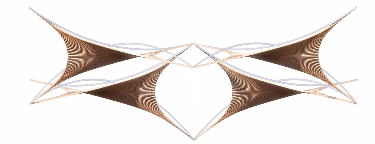
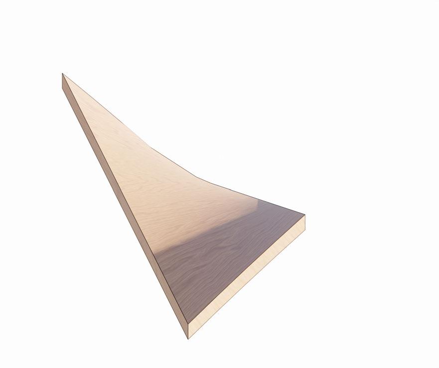
Lofting two non-parallel triangles generates three hyperbolic paraboloids (hypars) as the straight edges between them twist into doubly curved surfaces. This occurs because each triangle’s linear boundaries force the interpolation into a saddle shape.
ANTICLASTIC
ANTICLASTIC HYPERBOLIC PARABOLOID
Spicing Anticlastic Surface into Structural Sytsem
Design Research
Concept Development
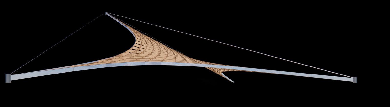
By slicing a hyperbolic paraboloid in half, I developed a spanning bridge structure—exploring how to harness its inherent structural efficiency while raising the question: how can we exploit the logic of the hypar without compromising its geometric purity?
Hypar Bridge Surface
The bridge surface was analysed for principal and perpendicular stress lines, ensuring the spliced hypar retained structural rigidity and integrity.
TENSILE
PRESSURE
Surface-Driven Urban Mobility and Accessibility Strategy
Design Research
Concept Development
This new study explores a multi-angled staircase derived from the hypar’s edge conditions. The varying angles create an embedded accessibility strategy—shallow inclines for ramps and seating, steeper sections for circulation—while preserving the structural logic of perpendicular principal stress lines for rigidity.
Hyperbolic Beam
Hyperbolic beams supports staircase providing multiple angles for a range of accesibility.
Interstitial Surface - Optimising Large Scale Urban Mobility
Design Research
Concept Development
Interstitial surfaces were explored as catalysts for urban mobility, drawing from Claude Parent’s oblique principles. This research informed hyperbolic paraboloid geometries, where anticlastic curvature generates gradient thresholds that choreograph movement without barriers, transforming circulation into spatial continuity.
Claude Parent
Claude Parent’s oblique theory reimagines architecture through inclined planes, replacing flatness with dynamic slopes that redefine movement, space, and habitation
Applying Interstitial Boundaries to Hypar
Hypar geometries materialize interstitial boundaries through anticlastic curvature, creating gradient thresholds that dissolve rigid program divisions while maintaining structural and circulatory coherence.
Interstitial Boundaries
Enhancing urban mobility by integrating curvilinear inclined planes
Gradient Thresholds
Urban mobility is enhanced with curvilinear gradient thresholds.
Spatial Continuity
Drawing a competitive compound bow can require up to 28 kilograms (60 pounds) of force.
Modularising Anticlastic Interstitial Artefact
Design Research
Concept Development
This research explores the modularization of hyperbolic paraboloid (hypar) geometries to create adaptable structural systems. By dissecting anticlastic surfaces into prefabricated timber or steel units, the project develops a kit-of-parts that reconfigures interstitial thresholds—enhancing urban mobility through reconfigurable ramps, bridges, and canopies. The system leverages hypar curvature’s inherent rigidity to minimize supports while maintaining spatial fluidity between programs.
PERMEATED SURFACE ENCLOSURE
3-1 ANGLE TO ANGLE
Vertical and Horizontal Circulation
Modular system of oblique planes allows for vertical and horizontal circulation paths.
Permeable Surface Enclosure
Permeable surface is enclosed and protected from the elements.
Single Level to Multi-Level Circulation
Interstitial artefact passively allows for circulation from one level to multiple levels.
Rationalising Modularised Structural System
Design Research
Concept Development
Exploring an embedded strcutural system within the modularised hypar urban mobility artefact, Contouring the geomtry along the x-axis endures that circulation is not blocked.
Purity of Hypar
Modularising hypar potnetially interferes with the structural purity of the hypar and disrupts optmisied principal stress lines.
THE HYPÆR DERBY
CONCEPT DEVELOPMENT
Layering Urban Fabric - Urban Mobility Strategy
Design Research
Concept Development
Conventional pedestrian/vehicular crossings create conflict points through abrupt level changes. Hypar geometries enable smooth grade transitions—their anticlastic curves naturally ramp and bridge, separating flows without stops. This structural surface stitches urban layers seamlessly, turning intersections into continuous spatial experiences.
Conventional Pedestrian/Vehicular Crossing
Clash appears when two converging pedestrian and vehicular paths cross.
Hypar Pedestrian/Vehicular Crossing
Hypar ramps enable seamless pedestrian flow over roads, eliminating stops through gradual 8° slopes that merge walkways with bridges
Surface Driven Accesibility Strategy
Design Research Concept Development
The hypar’s anticlastic geometry enables three triangular entry points within one system, where curved ramps (6% slope) seamlessly merge interior/exterior spaces. This creates intuitive, barrier-free circulation—elevators, stairs, and walkways unify under a single warped plane, dissolving conventional thresholds.
Triangular Flow
3-directional access
Spatial Fluidity
No abrupt transitions - fluid spatial interface.
Anticlastic Surface Landscape Integration
Design Research
Concept Development
The triangular hypar system mirrors landform contours, its three-directional geometry blending with topography. Curved planes transition seamlessly between built and natural elements, creating terraced gardens, shaded pathways, and storm water channels within one continuous surface.
Ingegrating Accesibility Strategy into Landcape
Design Research Concept Development
This architectural system of undulating surface mirrors natural topography while embedding universal access—gentle 5% ramps and tactile pathways discreetly woven into the terrain ensure wheelchair users navigate all zones seamlessly, merging fluid circulation with inclusive design.
Access Points
Points of access for wheelchair users within system which allows for an accessibility strategy that enhances landscape integration.
Landscape Continuity - Embedded Surface
Design Research Concept Development
The terrain-mimetic architecture creates a restorative environment where patients access nature therapy seamlessly. Gentle ramps (1:20 slope) and immersive gardens merge, enabling wheelchair users to navigate sensory landscapes independently while curved roofs frame therapeutic sightlines to greenery.
Please note: ‘Therapy Centre’ programme was not continued
S-Shaped Landscape Integration System
Fluid ramps and terraces mirror natural topography while enabling universal access across the ‘therapy center’s’ restorative gardens
S-Shaped System
Curvilieanr geometry that converges to one point is diffcult to resolve strucuturally.
Enhancing Viewing Experience
Design Research
Concept Development
Surface-driven studies demonstrate how anticlastic geometries seamlessly connect multi-level viewing platforms, enhancing spectator sightlines while optimizing urban mobility flows in large-scale stadium contexts.
PERMEABLE STRUCTURAL STRATEGY
Integrated Structure allows for change of level in interior spaces.
MAXIMISE VIEWS
Shearing the floor plates backwards enhances viewing experience and creates viewing platforms (interior/exterior).
L3
INCREASE URBAN FLOW/ LEVEL NAVIGATION
Pinching the ends allow all floor levels to arrive at the same level.
FOLLOW TRACK ANGLE
Angle of the track is folowed to ensure perpendicular sightlines.
Multi-Levelled Viewing
Design Research
Concept Development
Multi-levelled viewing platforms, enabled by surface-driven geometries, provide optimized vantage points—elevating sightlines for dynamic event perspectives while maintaining spatial continuity across the stadium.
Engineering Levels Below/Viewers Above
Three tiers of viewing evels are all above the track.
Unusable Space - Unresolvable Geometry
Floor levels tending towards one level creates unusable floorspace and becomes increasingly diffcult to resolve structural.
Drawing a competitive compound bow can require up to 28 kilograms (60 pounds) of force.
THE HYPÆR DERBY
SITE AND BRIEF
Wiltshire
Development
The site is situated in Wiltshire, England—a county renowned for its rural landscapes, historic landmarks (like Stonehnege), and proximity to key transport networks like the M4 and A303.
FORCE VECTOR
Drawing a competitive compound bow can require up to 28 kilograms (60 pounds) of force.
Saliisbury - Rail Connection
90 mins to London by rail. 30 mins to Bath. Site & Location
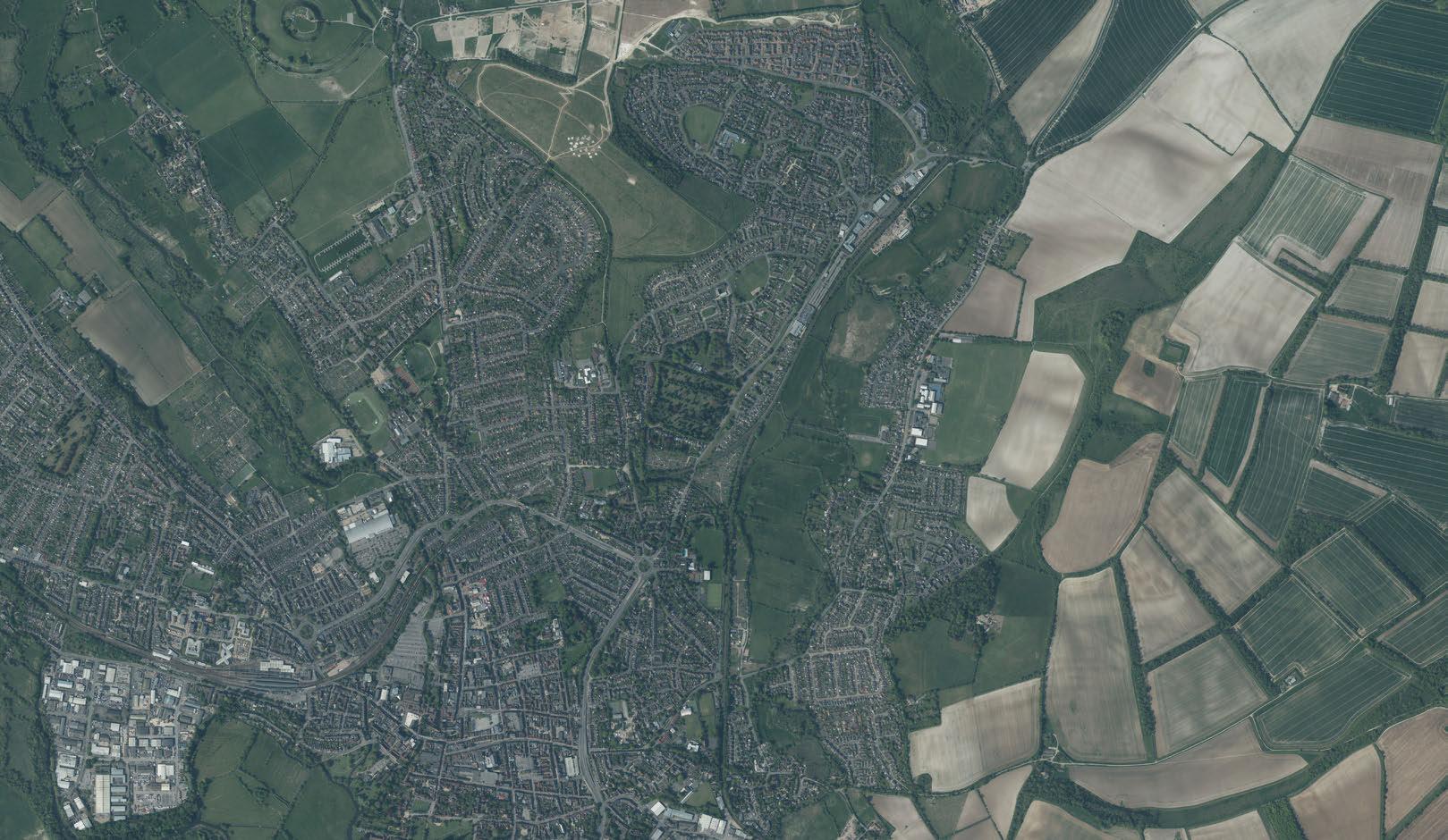
The site is located in Wiltshire, England, approximately 5 miles northeast of Stonehenge. It borders the A303 road, railway and sits within the River Bourne Wiltshire
Salisbury Sights of Interest
Salisbury, England, features a medieval cathedral, historic railway station (1847), and former horse racetrack (defunct 1898), blending heritage with transport links in a compact urban center.
Location of Sights of Interest
All within 3km of site.
SALISBURY
ACKLING DYKE HILL FORT
Site Location
The site is located in Wiltshire, England, approximately 5 miles northeast of Stonehenge. It borders the A303 road, railway and sits next to the River Bourne.
Urban environment to the west and rural agricultural landscape to the right.
URBAN
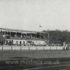
Located near Netherhampton, Salisbury Racecourse offers picturesque countryside views, flat racing events, and functional grandstand facilities for enthusiasts.
Gothic cathedral with a 123-meter spire, historic Magna Carta, serene Cathedral Close, and stunning architecture dating back to 1258.
Rolling chalk downs, including Old Sarum, offer historic sites, panoramic views, and trails amidst Salisbury’s scenic countryside.
Victorian-style station connecting Salisbury to major cities; features arched windows, modern facilities, and proximity to the city centre.
THE
A NEW ERA OF RACING HERITAGE
Site & Location Brief Development
“THE HYPÆR DERBY” re-imagines the world of motor sport by fusing the rich traditions of horse racing with the cutting-edge technology of Formula 1. This project aims to transform the cultural essence of equestrian sports into a dynamic, sustainable future for electric racing. Drawing inspiration from the rituals, architecture, and atmosphere of historic UK racetracks.
ECONOMIC CONTRIBUTION (UK)
GENERATES £4.1 BILLION ANNUALLY, INCLUDING INDUCED ECONOMIC IMPACTS.
ATTRACTS 4.8 MILLION SPECTATORS ANNUALLY, THE UK’S SECOND-LARGEST SPORT.
SUPPORTS 85,000+ JOBS IN TRAINING, BREEDING, AND EVENT MANAGEMENT.
GENERATES £2.57 BILLION IN REVENUE, BOOSTING THE LOCAL ECONOMY.
480,000 ATTENDEES FOR THE BRITISH GP, ONE OF F1’S LARGEST EVENTS.
SUPPORTS 100,000+ JOBS IN ENGINEERING, EVENTS, AND MEDIA.
TRACK DESIGN AND MAINTENANCE
PROGRAMME DEVELOPMENT
SITE SALISBURY
VISION
BY BLENDING THE TIME-HONOURED SPIRIT OF HORSE RACING WITH THE INNOVATIVE, ECO-CONSCIOUS FUTURE OF FORMULA E, THIS TRACK CREATES A NEW CULTURAL EPICENTRE WHERE THE TRADITIONS OF SPEED EVOLVE FOR GENERATIONS TO COME.
RACING CULTURE AND TRADITIONS
BETTING AND ECONOMIC IMPACT
ANIMAL WELFARE AND ETHICS
HORSE RACING
SITE SALISBURY
FORMULA 1/E
BREEDING AND TRAINING
FUSE HERITAGE AND INNOVATION
PROMOTE SUSTAINABILITY
THE ELECTRIC DERBY
URBAN MOBILITY
OBJECTIVES
ATTRACT AND ENGAGE DIVERSE AUDIENCES
ENHANCE COMMUNITY AND ECONOMIC IMPACT
DEVELOP A LEGACY OF EXCELLENCE
RACING TECHNOLOGY AND INNOVATION
SUSTAINABILITY AND ENVIRONMENTAL IMPACT
FAN EXPERIENCE AND ENGAGEMENT
URBAN INTEGRATION AND INFRASTRUCTURE
HERITAGE OF HORSE RACING IN THE UK
Horse racing in Britain began with Roman chariots, evolving into medieval match races. The Jockey Club (1750) standardized rules, while iconic events like the Derby (1780) and Grand National (1839) shaped its prestige. Today, the UK hosts world-class flat and jump racing, blending centuries-old tradition with cutting-edge breeding and training.
Racing
Elite thoroughbreds race at 60kph, governed by welfare standards and 300 years of British tradition.
Betting
Bookmakers use algorithms to set odds, while anti-fraud systems monitor £3bn annual UK wagers.
Drinking
Champagne bars and pubs fuel raceday revelry, balanced by responsible service initiatives.
Breeding
Genetic selection produces champions, with stud fees reaching £300k for elite bloodlines.
Huge Track
One Distant Grandstand Problem
Newmarket, Royal Ascot and Chetenham - Track Anatomy
Notable UK horseracing tracks. Scale preserved.
Terrible Sight-lines 0
THE HYPÆR DERBY
ETHICAL CONTEXT AND CONSIDERATIONS
(A Response to Traditional Motorsport & Equestrian Controversies)
3,500+ racehorses die annually worldwide from injuries, overbreeding, or euthanasia after failed careers.
52 driver deaths since 1950, including recent incidents like Anthoine Hubert (2019).
HIGH HORSE MORTALITY
BRUTAL TRAINING PRACTICES OVER BREEDING & WASTAGE
HORSE RACING
DOPING & DRUG ABUSE
& INJURIES
OBJECTIVES
Eliminate Animal & Human Harm
Zero animal use: Replace live horses with AI-powered robots (no breeding, doping, or slaughter).
No human danger: Remove jockeys/drivers; operators control robots remotely.
THE HYPÆR DERBY
Decarbonize Racing Democratize Access & Profit
100% renewable energy: Solarpowered racecourses; robots charged via green grids.
Robots built from recycled materials (e.g., repurposed F1 parts).
Revenue shares for former horse-racing workers. 1 2 3
Affordable tech: Open-source robot designs to lower entry costs.
Local co-ops fund teams (vs. oil sponsors).
Ethical Considerations of Robot Horse Racing vs. Traditional Sports
Ethical Issue F1 Racing
Human Fatalities
52 driver deaths (1950–2023)
Animal Fatalities N/A
CO2 Emissions
Economic Barriers
Doping/Cheating
Gambling Harm
Labour Exploitation
Cultural Impact
256,000 tons/year (per team)
$140M+ team budgets
12 F1 team violations (2022)
$150B annual global F1 bets
Pit crew: high injury rates
70+ years of global fandom
Traditional Horse Racing
1,000+ jockey injuries/year (globally)
0.25 km² (25 hectares)
~2,550 tonnes CO2e
500K–5M/year to stable a racehorse
Robot Horse Racing
Zero human risk
No animals used
Renewable energy possible
Lower entry cost (no livestock)
4% of racehorses fail drug tests (UK, 2023) Transparent AI algorithms
$115B horse racing bets (2023)
Stablehands: 60% below living wage (US)
300+ years of tradition)
Major Oil Sponsors in F1 + Greenwashing Tactics
Title sponsor of Ferrari (2023+)
Funds Arctic drilling; $23B/yr oil investments
McLaren technical partner
Climate denial lobbying (exposed in 2015)
Similar risks, but auditable
Tech jobs require fair wages
Needs new fan engagement models
Global F1 partner (Saudi Arabia)
Linked to Khashoggi murder; world’s largest oil producer
Mercedes team sponsor (since 2010)
Malaysian oil giant; deforestation lawsuits
Timeline of Major Events (and Disasters) in F1 and Horse Racing
HORSE RACING
History of Horse Racing and F1 in England
Site & Location
1947: POST-WAR RESURGENCE
1973: SECRETARIAT’S TRIPLE CROWN
Brief Development
1903: WEIGHT-FOR-AGE SCALE INTRODUCED
1920: MAN O’ WAR’S DOMINANCE
1947: POST-WAR RESURGENCE (ROYAL ASCOT)
1968: PHOTO-FINISH TECHNOLOGY INTRODUCED
1984: BREEDERS’ CUP INTRODUCED
1990: DUBAI WORLD CUP GAINS PROMINENCE
2020: VIRTUAL RACES DURING COVID-19
1920: MAN O’ WAR’S DOMINANCE
1950: F1 WORLD CHAMPIONSHIP BEGINS
1955:
1967: AERODYNAMIC WINGS INTRODUCED
2014:
2021: VERSTAPPEN-HAMILTON SHOWDOWN
1950: F1 WORLD CHAMPIONSHIP BEGINS
LE MANS DISASTER IMPACTS SAFETY
1955: LE MANS DISASTER IMPACTS SAFETY
1976: HUNT VS. LAUDA RIVALRY
1976: HUNT VS. LAUDA RIVALRY
1977: TYRRELL P34 6-WHEELER BANNED
1977: TYRRELL P34 6-WHEELER BANNED
1988: SENNA VS. PROST RIVALRY
1988: SENNA VS. PROST RIVALRY
1994: AYRTON SENNA’S DEATH
HYBRID ENGINE REGULATIONS
UK Motor Sport Precedent Analysis
Precedent analysis of famous UK motor sport tracls was undertaken to understand the scale of tracks. Silverstone, Brands Hatch and Donnington are all vital tracks in the formation of popularity for motor sport in England.
Silverstone, Brands-Hatch and Donnington
Famous UK racetracks.
5.891 km (3.661 miles) –Current Grand Prix Layout
Scale of Silverstone vs Site
Site & Location Brief Development
F1 circuits (3–7km) prioritize high-speed straights and technical corners for aerodynamic testing, while horse tracks (1–2.5km) emphasize tight turns and banked curves for agility. The shorter, repetitive laps of racing differ from F1’s endurance-focused layouts.
Site (to Scale)
The site is large enough for track, stadium, grandstand and amenities.
Silverstone (to Scale)
racetrack can be half the size of Silverstone racetrack.
Horse
Spatial Adjacencies - Masterplan
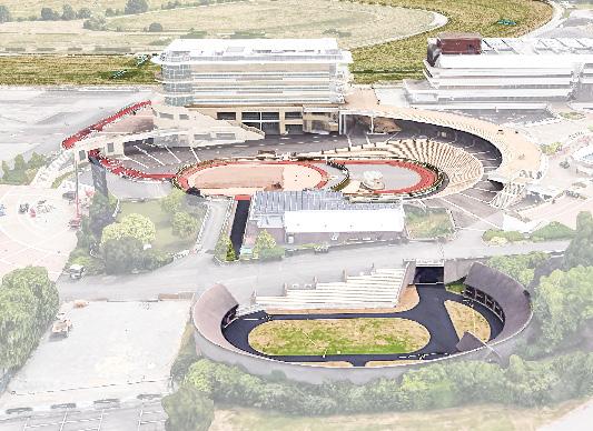
MASTERPLAN
SPATIAL ADJACENCIES
The spatial masterplan highlights the interconnections and alignment of key programmatic elements. The design emphasizes seamless urban and rural integration, optimized flow, and the strategic positioning of spaces to support both functionality and user experience. Each component is carefully placed to maximize efficiency, accessibility, and interactivity while maintaining a coherent spatial hierarchy.
Functional Adjacency Diagram
Initial investigation into spatial adjacencies for a racetrack environment aiming to hybridiz3e viewing experience and connectivity.
ACCESS
CIRCULATION ZONE
SKYWALK
MAGLEV TRANSPORT LINK PARK ACCESS
LOOP
PIT STOPS
OBSERVATION DECKS
VIEWING GALLERIES
FOOD AND RETAIL
MAIN RACE TRACK
ROBOTICS ENGINEERING LAB
BETTING FACILITIES
PARKING AND TRANSIT HUB
PEDESTRIAN CIRCULATION
MAIN RACE TRACK
URBAN PARK
MAGLEV
CENTRAL PLAZA
Programmatic Alignment and Triangular Orientation
Programmatic alignment (stadium, track, subterranean access) linked by functional and experiential relationships. Three-sided layout clusters amenities efficiently while framing optimal track sightlines from all spectator zones.
TRI-CIRCULATION
Platform
Stadium Secondary Grandstand
Track
Straight, clockwise track, clustered amenities and a central stadium/ paddock. Main
Site Introduction: Environmental Analysis
Site & Location Brief Development
The triangular site integrates solar optimization (south-facing tex), and flood resilience (River Bourne ponds). Solar orientation reduces energy demand, while railway connectivity cuts carbon emissions. Permeable paving and bioswa lakes that attenuate flood peaks. Earth berms (3m) lined with native flora dampen noise and stabilize soil, harmonizing acoustic and ecological functions.
Embedded Seating in Hill to Reduce Wind Exposure
Seating is embedded into hillside topography, leveraging natural landforms to buffer wind exposure. This enhances spectator comfort, reduces thermal loss, and maintains unobstructed sightlines to the track.
Wind Exposure:
Seating is embedded into Landscape on South West Hill. The dirt from sunken track is used to create hill which protects stadium from Wind Loads.
Microclimate:
Berms shield spectators from crosswinds, enhancing thermal comfort.
Prevailing Wind Direction:
Track is oriented in line with SW prevailing winds to give robot racers a speed boost with the tailwind.
River Bourne:
River Bourne runs on the east side of the site and creates a flood risk during heavy rainfall.
Lakes and ponds are strategically integrated into the track’s design, capturing storm-water runoff to mitigate inundation.
Triangle Orientation:
Triangle is oriented to allow access directly into entrance from railway and road access in the NW.
Triangle is also oriented to have long face on SW side for wind protection and PV solar energy harvesting.
Rainwater Collection Ponds:
Stormwater lakes double as protected habitats for endangered great crested newts, merging flood control with biodiversity conservation.
On-Site Tree Cultivation Strategy
Site & Location Brief Development
Problem: Conventional timber sourcing requires long-distance transport (high embodied carbon) and lacks circularity.
Solution: An on-site 1,275-tree plantation that grows with the stadium, serving as:
Carbon sink (offsetting 2,550t CO2e over 30 years)
Future material bank (15% harvested for CLT/beams)
The variable-thickness polar beam/column array strategically adjusts cross-sectional dimensions to match bending moment distribution, reducing material waste while maintaining structural performance.
1. Tree Planting Plan (30-35 Year Cycle)
Metric
Total Trees
Site Area
Carbon Sequestration
Harvest Rotation
Construction Use
0.25 km² (25 hectares)
~2,550 tonnes CO2e
30-35 years
15% of Mature Trees
2. On-Site vs. Imported Timber Comparison
Factor
Carbon Footprint
Cost
Quality Control
Time to Use
0 transport emissions
£0 (after 30-yr growth - planting costs)
Species/growth monitored
30-year delay
80-85% (20% reduced carbon)
Mixed native species (oak, beech, pine)
51 trees/hectare (optimal density)
2 tonnes/tree over 30 years
Matches timber curing time for LVL
Sourced for beams/cladding (if needed)
1.2kg CO2e/km (by truck)
£85/m³ (+ shipping)
Variable supplier quality
Immediate availability
Hybrid Poplar: Known for its rapid growth rate, it can grow up to 2 meters per year.
Eucalyptus: Popular for its fast growth and high-density wood, making it suitable for timber.
Paulownia (Empress Tree): This tree can grow 10-20 feet in its first year and reaches maturity within 10 years, making it one of the fastest-growing hardwoods.
Sycamore: A robust tree that offers ample shade and can withstand challenging weather conditions.
Walnut, Oak, Maple, Cherry, Ash, Birch: These species are also noted for their high-profit potential and relatively fast growth. These trees are ideal for quick shade, timber production, and environmental benefits.
Track Undulation - Spa-Francorchamps
Site & Location
Precedent Study
Precedent analysis examines Spa-Francorchamps’ track undulation and Eau Rouge’s elevation change, demonstrating how strategic curves enhance dynamic viewing from grandstands—informing this project’s sightline optimization.
Eau Rouge
Senna driving Eau Rouge in a Mclaren MP4
Spa-Francorchamps
Level change of 50m exoerienced by drivers around Spa-Francorchamps
Facade Interface - Circuit de Monaco
Site & Location Brief Development
Monaco’s facade study reveals how sightline angles shift with corner severity and car speed—guiding grandstand placement at collision/overtaking hotspots to maximize spectator engagement with dynamic race moments.
Facade with direct sightline to Track
Facade interface with track at Circuit de Monaco
Direct sightlines include yachts in harbour. Tunnel blocks all sightlines.
Monaco Harbour
Programme Introduction
Horse racing in Britain began with Roman chariots, evolving into medieval match races. The Jockey Club (1750) standardized rules, while iconic events like the Derby (1780) and Grand National (1839) shaped its prestige. Today, the UK hosts world-class flat and jump racing, blending centuries-old tradition with cutting-edge breeding and training.
Royal Ascot 1964
Royal Ascot, founded in 1711 by Queen Anne, has been Britain’s premier horse racing event for over 300 years, maintaining its royal traditions.
Biology of Racehorse
Thoroughbreds: 500 years of selective breeding for speed, stamina, and elite cardiovascular performance.
Grand National (1839)
The Grand National, first run in 1839 at Aintree, has been the world’s most famous steeplechase for 185 years, thrilling spectators with its challenging fences and unpredictable finishes.
Adapted ATST
AI-driven, carbon-fiber robot racehorses: precision galloping, zero fatigue, and programmable agility for next-gen sport.
The decline of traditional horse racing—due to ethical concerns, aging audiences, and financial instability— has created a void for a sustainable, high-tech alternative: Robotic Horse Racing. This new sport merges the heritage of equestrian competition with cutting-edge engineering, AI, and immersive entertainment. The Future of Horse Racing is Robotic: A Next-Gen Sport Reborn
Revenue Streams & Business Model
Site & Location Brief Development
Revenue Stream Breakdown
Stream Stream Year 1(Est.) Profit Margins
Broadcasting40-50% 80M
60–70% (low production cost vs. F1)
50–60% (high takeout, AI-driven odds)
80%+ (digital ads, sponsorships
40–50% (VIP/metaverse upsells)
Total Margin: ~55–65%
SECONDARY REVENUE STREAMS
4.5 Project Timeline
The seven RIBA stages are: Preparation (briefing), Concept Design (initial ideas), Developed Design (refinement), Technical Design (detailed specs), Construction (building), Handover (delivery), and Post-Occupancy (evaluation).
RIBA PLAN OF WORK
The RIBA design stages are Stage 2 (Concept Design), Stage 3 (Spatial Coordination/Developed Design), and Stage 4 (Technical Design)
PROJECT TIMELINE
Please note: Each circle represents a month.
ROLES AND RESPONSIBILITIES
Drawing a competitive compound bow can require up to 28 kilograms (60 pounds) of force.
This timeline inidcate the goals and actions for each stage of RIBA Plan of Work.
RIBA Stage 1: Preparation & Brief
Goal: Define requirements
Actions: Finalize seating capacity (50,000), Robotics track specifications, Sustainability targets (Net Zero by 2035)
Preperation and Breifing
Design
1 2 3 4 5
RIBA Stage 2: Concept Design
Goal: Develop Concept Design, Visuaize Stadium
Actions: Triangular roof + track 3D models, Prefab vs. traditional cost comparison, Stakeholder sign-off, planning application submitted to Salisbury City Council.
Goal: Define requirements Actions: Finalize seating capacity (25,000), Robotics track specifications, Sustainability targets (Net Zero by 2035)
(6-8 months)
RIBA Stage 5: Construction
Goal: Build the stadium
Phases: Foundation (2mo), Concrete Support Walls and Rafters (3mo), Prefabricated Seating Blocks (4mo), Floating Timber Roof Construction (4m), Detailing & Finishing (3m), Landscaping (2m)
(14-18 months) (2-3 months)
THE HYPÆR DERBY
ARCHIE KOE
Tattershall Auction House - Newmarket
Sectional Condition
Precedent Analysis
The auction hall features three seating tiers: (1) Ground-floor ringside benches for buyers/inspectors, (2) Elevated gallery seating for observers, and (3) Private boxes for high-value bidders—all oriented toward the central sales ring.
Initmate Racehorse Interface with Bidders
Understanding the sectional conditions to deduce how racehorses are auctioned to the highest bidder.
THREE CONDITIONS
Three sectional conditions of Tattershall bloodstock auction hall.
AUCTIONEER’S SECTION
SEATED
OPEN ENTRANCE - DUAL ENTRANCE
Speculation on Mirroring Conditions for Dual Purpose Architectural System
Racetrack viewing hybridized with paddock in same structural sytsem.
View Defined Sectional Conditions
GEOMETRY EXPLORATION
MODULAR COMPOSITION
The sectional strategy draws inspiration from Tattershall Auction House’s vertical layering, reimagined here as a flipped duality: the outer perimeter frames dynamic track views (racing spectacle), while the inner triangular core houses the paddock (also used for bloodstock auctions).
SECTIONAL FRAGMENT EXPLORATION
The three different sectional conditions developed to serve two functions: track viewing on the outside and paddock viewing on the inside.
OCCUPIED ROOF - AUCTIONEERS
Auctioneers Stand doubles up with shallow track viewing.
DOUBLE SIDED SEATING
Double sided seating uses the same central column and acts as counterbalance cantilever.
ENTRANCE
Entrance allows for easy acces with long cantilever for rain protection.
Structural Logic: Dual-Purpose Ring Configuration
The concentric ring structure places the racing track on the outer perimeter with the inner paddock courtyard, creating dual-purpose spaces that maintain clear functional separation while sharing a unified architectural form.
Programmatic Response to Mirrored View Conditions
Hybridizing view based programme in mirrored configuration.
Occupied Roof
Paddock View Seating
Track View Seating
Entrance
Subterranean Engineering Workshop
TRACK
TRACK
PADDOCK
PADDOCK
PADDOCK
Genesis - Global Massing
GLOBAL MASSING
Site Selection & Contextual Response
Key Features:
GENESIS
Transport Links: 5km to Salisbury Railway Station (shuttle buses), Direct access to A30/A36 (new roundabout proposed).
The global massing reflects the response to viewing conditions, programmatic zoning, accessibility and existing site conditions.
View Study
Hybridizing view based programme in mirrored structural configuration
AUCTION HOUSE OCCUPIED ROOF
PADDOCK VIEW SEATING
TRACK VIEW SEATING
ENGINEERING STABLES
Interior seating has a more intimate, higher angle seating which allows spectators to view horses up close.
The floating timber roof serves two functions; protecting spectators fromthe elements and providing a higer platform for VIP viewing.
Exterior seating areas has a shallow angle for enhanced sightlines and a higer volume of seatin.
Shallow Angle Track Viewing
High Angle Paddock Viewing
Floating Timber Roof
Programmatic zoning for F&B, Engineering and Betting Facilities.
OCCUPIED ROOF
ENGINEERING
Orientation & Geometry of Racing Tracks
Masterplan Development Acoustic Strategy
Orientation and Geometry of racetracks has a profound affect on the viewing experience. The architecture must respond to the speed of the corner, the racing line and the direction of the race. To maximise the viewing experience, both the track and architecture must be designed to respond to each other.
Straight, Chicane and Corner
A Strategic Analysis for Robotic Horse Racing Design
As the available racing lines converge at a slow corner the chance of collision/overtake dramatically increases.
Spa-Francorchamps
Talladega Speedway
During the F1 at Circuit de Monaco, the treatment of race viewing is more vertical at the facade interaction. This allows for a longer duration of viewing as the cars speed past.
During the F1 at Spa-Francorchamps, a grandstand is strategically between the two corners of the chicane at the ‘Eau-Rouge’ corner. The heightened activity of collisions during the race at the chicane increases viewing desire.
During the Indy 500 at Talladega Speedway, the track banks with a 30 degree camber. This track response is to allow the cars to travel at a faster speed around corners. To decrease speed at corners, my track will not include camber at important corners.
Circuit de Monaco
CHICANE
CORNER
Ascot Precedent Analysis
Straight, Track and Direction
Triangular Track
A triangular track was favoured as it combined the excitement of F1 sharp corners with the functionality of the straight and track integration.
At Ascot racetrack, the horse interacts with three main ‘tracks’, the stable, the paddock and the track. The continuity between these three separate surfaces is limited. I aim to enhance interaction of these ‘tracks’ by applying ttriangular geometry.
It is important to consider the direction of the race to understand the locations of increased activity for overtakes and collisions. The horses have an advantage if they run on the inside following the racing line.
Speed Variation affect on Noise Output
Masterplan Development
Masterplan Development Acoustic Strategy
Orientation and Geometry of racetracks has a profound affect on the viewing experience. The architecture must respond to the speed of the corner, the racing line and the direction of the race. To maximise the viewing experience, both the track and architecture must be designed to respond to each other.
Programmatic Alignment and Triangular Orientation
Programmatic alignment (stadium, track, subterranean access) linked by functional and experiential relationships.
Three-sided layout clusters amenities efficiently while framing optimal track sightlines from all spectator zones.
Acoustic Zoning - Programmatic Response
Open-air design, crowd noise, robot hoof sounds
Earth Berms - Track Articulation
3m high earth berms articulate around track which reflect propagating sound waves upwards
Reflection pools reflect the sound of the robot racers as they speed past. Harvesting the noise and exaggerating the acoustic environment to enhance viewing experience.
The masterplan centres a stadium encircled by a dynamic track, zoning its entrance with a subterranean section for seamless access. The asymmetrical track design—featuring sharp corners, chicanes, and a long right-hand straight—engineers speed variation, amplifying spectator thrills through unpredictable racing lines and strategic overtaking zones, blending topography with high-octane spectacle.
High-Action Zones
Red dots mark high-action zones—sharp turns and straights where collisions or overtakes most likely occur.
SUBTERRANEAN CORNER
Racing Diversity
Sprint vs. endurance tactics unfold simultaneously.
Visibility Economy
80% of track visible from key grandstands.
Hybrid Experience
Varied corners hybridize viewing thrills; looped track design delivers diverse racing action from single vantage points.
CHICANE
Construction Sequence
Phase 1: Excavation & Pile Foundation
Duration: 8 weeks
Key Activities: Topsoil removal + geotechnical stabilization, Driven RC piles (Ø600mm, 25m deep) at 5m grid points, Laser-graded raft foundation with waterproofing membrane
Phase 4: Prefabricated Seating Blocks
Duration: 5 weeks
Key Activities: Modular GRC seating units (3m x 2m) craned into place, Epoxy-anchored to rafter ledges, Expansion joints every 15m.
This timber roof structure requires meticulous execution—strict safety protocols for overhead lifts, certified rigging, and sequenced assembly.
Phase 3: Prefabricated Rafter Installation
Duration: 4 weeks
Key Activities: 150-ton crane lifts 12m precast concrete rafters, Bolted to wall embeds with M64 HSFG bolts, Temporary propping until roof is complete.
Phase 6: Secondary Structure Attachment
Duration: 8 weeks
Key Activities: Bolt curved glulam ribs to primary beam (400mm centers), Install CLT roof panels with slip-resistant walkways
Safety: Temporary edge protection nets
Phase 9: Landscaping & Crane Demobilization
Duration: 10 weeks
Key Activities: Shape acoustic earth berms around lakes, Install native drought-resistant planting, Dismantle cranes via 200-ton mobile crane.
Occupied Timber - Elevated Viewing Experience
Synthesis Design Development
The timber bridge system optimizes VIP sightlines to both paddock and track. Angled interior facades within the triangular roof frame enhance viewing angles, creating dual vantage points from elevated seating platforms.
Optimising Sight-line into Paddock and Exterior Track
The angle facade on the interior face of the triangular roof system is angled to increase opportunity to view the paddock for the VIP members.
Previous Design
The previous design for the floating roof had a non-planar floor which resulted in unusable space.
Resultant Change of Design
The exterior edge of the roof became level with the primary structure do reduce load on cantilever and to maintain datum.
Maintaining Datum of Exterior Edge
The previous design for the floating roof had a non-planar floor which resulted in unusable space.
Overall Structural Strategy
Synthesis Design Development
Timber hypar shell and torsion box cantilever over concrete walls, transferring thrust/ tie forces to spread footings via axial load paths.
ROOF STRUCTURE
The roof design uses a polar array of columns with variable cross-sections instead of a conventional truss system to improve efficiency. This radial layout directs loads toward a central support, reducing bending moments. The columns are optimized by thickening at high-stress areas (mid-span) and tapering where loads are lower.
Structural Shell
Doubly-curved timber hypar shell directs compression/ tension along anticl astic geometry for efficient load transfer.
Torsion Box ‘Monocoque’
Radially-oriented closed timber box resists twist while aligning with hypar’s principal stress trajectories.
Cantilever Beams
Tapered timber beams leverage thrust-pull action to counteract deflection under asymmetric loads.
BASE STRUCTURE
The base uses reinforced concrete to handle increased live loads from crowd movement. Its strength and rigidity distribute dynamic forces, minimize vibrations, and ensure stability and durability under heavy use.
Grandstand Seating
Precast concrete terraces transfer live loads vertically while anchoring lateral stability ties.
Beam Support
Reinforced concrete beams convert moments into axial column/wall loads.
Vertical Timber Supports
Cast-in-place shear walls provide lateral stability and distribute foundation loads.
Foundation/ Basement
Spread footings/piles resolve vertical, uplift, and overturning forces into stable strata.
Structural Principles of Overall Stadium Design
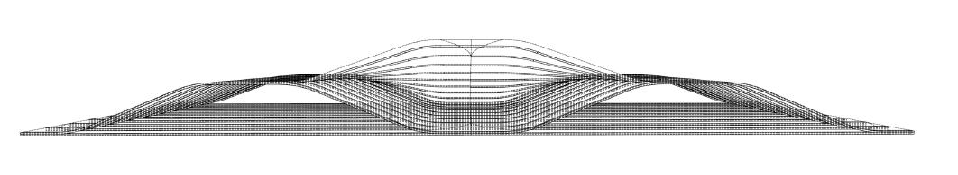
Synthesis Design Development
The concrete base transfers loads simply through shear walls and columns. Above, the timber roof employs optimized cross-section beams forming a monocoque torsion box, resisting cantilever forces through continuous surface action. Principal stress lines naturally wrap around this structural shell, creating efficient load paths without cross-bracing.
The primary structure consists of a vertically spliced cantenary beam that is anchored to the foundations with a steal blade connection
Principal Stress Trajectories (Nonlinear
The structural surface acts to redistribute principal stress lines, supporting the downwards.
Shear Lag (Stress Concentration in Wider Sections)
In wide cantilevers, stresses concentrate near supports, creating: Tension “fanning” near fixed ends, Compression “arching” toward the tip.
Grandstand Seating
Load Transfer
Grandstand seating, constructed from precast concrete rafters, transfers gravity loads and wind loads into primary structure.
Floating Timber Roof Structural
Cantilever Beams
Structural Surface
(Nonlinear Flow of Forces)
redistribute stress along the curve of the the cantilever roof from deflecting
Three Plinths
The location of the three plinths for the roof-grandstand interface are at the three corners of the equilateral triangle.
Load Distribution - Structural Maquette
A three-pointed structural maquette was modelled to understand the laod distribution of a catenary arch as a priamry compressive ring.
Vertical Splicing - Catenary Beam
The primary catenary structure requires thoughtufl splicing to unerstand the vertical defelction and the torsional forces.
Cantilever Deck
Torsional Resistance
seating area in the VIP roof applies uneven loads, the cantilever resist twisting (torsion), the cantilever relies on the structural surface mitigate torsion.
Midspan Height
The height of the midspan was important to consider; if it is to high the catanery arch will be too extreme and the load will not be evenly distributed to the primary structure.
Structural Surface
Tensile principal stress lines “wrapping around” the structure; forming the structural surface consisting of steam bent planks that run along the stress lines.
VIP Roof - Programme
Synthesis Design Development
VIP timber roof integrates betting lounges and a premium bar, offering dual views of the paddock and track. Elevated sightlines enhance the exclusive experience, merging high-end hospitality with immersive racing perspectives.
VIP Winter Garden, Bar and Betting Facilities
Private suites, champagne service, and interactive race data screens elevate the VIP experience further.
Auction Viewing
Winter Garden
Dual Sightlines
Winter Garden crowds increase cantilever live loads (5+ kPa), requiring torsion-resistant timber design for dynamic deflection control and asymmetric load distribution.
Viewing Platform
Race Viewing
VIP Bar
VIP Betting
VIP Sightlines to Paddock
VIP Sightlines to Racetrack
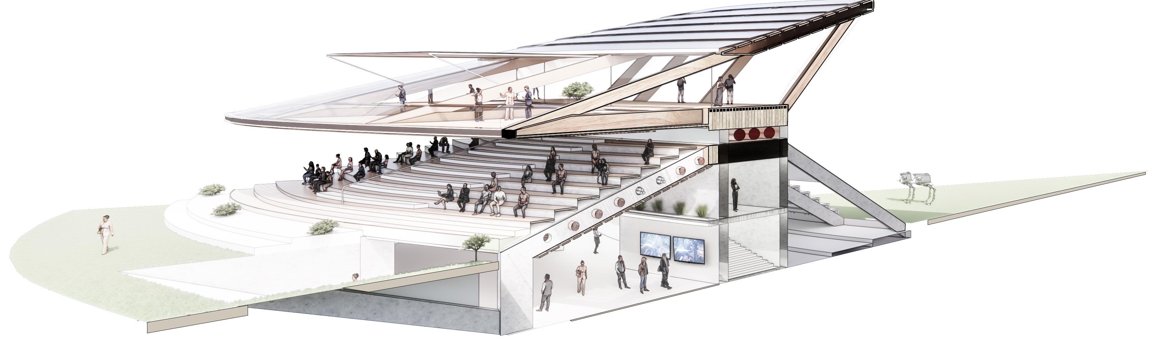
Programmatic Sectional Study
Synthesis
Design Development
The section stacks: VIP roof (lounges/bars) above grandstand seating, with betting/ circulation beneath. This vertical hierarchy optimizes views while separating flows - premium spaces elevated, public zones below, and spectator seating mediating between.
VIP Lounges (Conditioned but Adjacent to Hybrid Zones)
Air Infiltration: Leakage from semi-outdoor spaces forces HVAC to overcompensate (30% energy use).
Winter Gardens (Semi-Enclosed)
Summer Overheating: Glass-heavy areas trap solar gain, requiring dynamic shading + purge ventilation to prevent ∆T > 8°C swings.
Open Viewing Decks
Wind Chill Effect: Exposed areas feel 5–7°C colder than ambient in winter
Enclosed
Covered
Winter Garden
Live Load Variation - Load-Driven Material Response
Synthesis Design Development
Stadiums face extreme live load variations: packed seating areas require high-capacity concrete for durability and vibration control, while roof structures (subject to lighter, dynamic loads) optimize weight with timber’s strength-to-weight ratio.
Precedent Analysis: Tattershall Auction House Live Load Conditions
Three Conditions of Precedent Auction House - Tattershall Auction house
Auctioneer’s section, seated section and open entrance which doubles as a standing area for auction.
Bloodstock Auction House for Horse Racing
Highlighted in red shows the increase in live loads for the three separate sectional conditions.
VIP Roof - Low (0.5–1.5 kN/m²)
The VIP timber roof is designed to avoid concentrated live loads across its span, as the primary spectator area for racing (e.g., grandstands, viewing platforms) is located on the right side of the structure (aligned with the track’s
Stadium - High (4–7 kN/m²)
The stadium’s concrete rafters are parametrically tapered toward the left-side entrance, concentrating structural mass where live loads are lowest. Meanwhile, crowd loads (5+ kN/m²) focus on the right side, aligning with:
- Prime seating for the racetrack straight.
- High-density spectator zones (grandstands, concessions)
Increasing Exposure to Live Load
Load Comparison (Stadium vs. VIP Roof)
Load Type
(Concrete)
(crowds,
Total Design Load
Material & Structural Response
kN/m² (maintenance, wind)
LVL/Glulam beams + steel tension ring Dead Load
Capability
Sustainability
Wind uplift (>3 kN/m² in storms)
Why Chosen? 6–8 kN/m² (heavy concrete rakers) High mass resists vibration/impacts 1–2 kN/m² (lightweight CLT/LVL)
The vertically spliced primary structure must not be laterally split otherwise the compressive strength will be dramatically reduced.
Primary Timber Catenary Beam Bolted to blade, aligned with wood grain (parallel to tension forces).
Connection
High-strength bolts through steel-timber interface
Steel Blade - 25mm Thick
Running in the direction of the grain of the catenary beam do avoid disturbing the anisotropy of the vertically spliced timber primary structure.
Primary structure is anchored into place using a steel blade assembly which offsets lateral and vertical loading.
Plinth Condition
Wood Anisotropy
Steel Blade Concrete Anchorage
Vertical Wind Loading
Triangular profile can create a zone of negative pressure above the roof which can pull roof system upwards.
Previous Design
Previously, the plinth condition entailed the roof passively sitting on top of a butress foudnation wall.
Beam Connection to Primary Catenary Structure
Seamless steel plate beam-to-catenary connections ensure efficient load transfer and structural continuity.
Tensile Timber Connection
Tension-resistant timber joints transfer roof forces into torsion box securely.
Steel-Blade Advantage: High tensile strength resists uplift without adding bulk, curved shape matches natural catenary, minimizing stress concentrations.
Timber-Grain Alignment: Maximizes tensile capacity (wood is strongest parallel to grain). Prevents splitting at bolt points.
Concrete Embedment: Anchors blade against pull-out (shear keys or rebar enhance bond).
Forth Bridge Precedent - Cantilever Truss Bridge
Synthesis
Design Development
Forth Bridge’s cantilever-truss system demonstrates balanced tension/compression forces—a principle applied to this roof’s counterweight design, where rear cantilevers offset front spans via timber tendons, creating equilibrium for floating timber volumes in section
Forth Bridge
Anchor truss, cantilever truss and counterbalance.
Suspended Section
Foundations
Suspended Section
Cantilever Truss
Cantilever Truss
Deck
Cantilever Truss (Counterbalance Anchor Arm)
Anchor Truss
Anchor Truss
Human Demonstration of the Cantilever Principle for the Forth Bridge (1887-1889)
Triangular Orienation Options
VIP Roof Counterbalance Cantilever
Winter Garden crowds increase cantilever live loads (5+ kPa), requiring torsion-resistant timber design for dynamic deflection control and asymmetric load distribution.
For the roof design, a polar array of columns with variable cross-sections was selected over a conventional truss system to enhance efficiency. The polar arrangement radially distributes loads toward a central support, minimizing bending moments while leveraging cross-section optimization—thickening columns at high-stress zones (mid-span) and tapering them at lower-load areas.
Cross Section Optimization Benefits/Drawbacks
Aspect
Material Use
Deflection
100% reference
100% reference
Fabrication Simple
Truss Orientation
80-85% (20% reduced carbon)
85-90% (improved stiffness)
Variable section (20-75mm)
Truss system for the roof structure adds considerable weight if the cross section of truss members is limited at a minimum of 25mm. This added weight creates areas of exceedingly high compression at the corners.
High Compression Load
Compression Load
Tensile Load
Balanced Load
Array
Heightened Compression Load on Anchor Joint (Rt)
Midspan trusses are not effectively distributing force radially.
The radial array roof system dramatically reduces weight and requirement of wood which decreases carbon footprint. The only significant increase in force is with the bottom inner ring which is where the primary structure is placed.
Radial
Diagonal
Cross Section Optimization
The variable-thickness polar beam/column array strategically adjusts cross-sectional dimensions to match bending moment distribution, reducing material waste while maintaining structural performance.
25mm Cross Section
50mm Cross Section
75mm Cross Section
Build up of Anchor - Informed by Stress Analysis
Exploring Bifurcation for Tensile Anchor Joint
In a previous design, bifurcation was explored to understand the best redirection of tensile loads.
Resultant Change of Design
Instead of bifurcation of wooden elements, the radially arrayed torsion box was used to take advantage of structural surface.
Tensile Load on Anchor Member
Heigher Compession Load on Compression Ring
Anchor/Foundation Interface - Iteration
Synthesis
Design Development
Timber bifurcation was explored for tensile roof nodes but proved inconsistent under stress analysis. The final design adopted a monocoque torsion box—using CLT-LVL composites for uniform load distribution and torsional stability.
Three Plinth Location for Trussed Bridge Option
Trussed roof system required cross bracing which initiated the exploration if bifurcation with timber.
Tensile Foundation - Materiality
Steel was considered for the anchor interface with timber roof as high tensile forcesoccured at these nodes.
Tensile Node Bearing Force Reaction Force
Cross Bracing
Synthesis
Design Development
Cross bracing was considered but rejected in favor of a torsion box monocoque. The structural surface approach provided inherent stiffness through its hypar geometry, resulting in a cleaner, more efficient floating timber roof design.
Cross Bracing Options
Visual test of cross bracing from the arrival experience.
Load Path Transfer
Synthesis
Load Path Summary
Design Development
The structural system begins with the hyperbolic paraboloid roof’s doubly-curved surface, where anticlastic geometry naturally directs compressive stresses along arched paths and tensile forces along troughs, eliminating bending moments. These forces transfer to cantilevered monocoque timber torsion boxes that maintain rigidity while resolving thrust-and-tie actions to counteract deflection. The loads then flow axially through reinforced concrete columns and shear walls, finally dissipating into spread footings and pile foundations
Compression Load
Tensile Load
Closed-section timber torsion boxes transfer shear/torsion to supports
Foundations
Torsional shear force spiral along the anticlastic surface, resisted by the monocoque box’s
Tensile beam resolve forces, reducing deflection via thrust-pull equilibrium.
Spread footings/piles distribute vertical/uplift forces to soil
Monocoque Beams
Prefabrication - Precast Rafter System with Piezoelectric Harvesting
Synthesis Design Development
This system uses two prefab rafter types: standard and stair-integrated. Factory-cast concrete rafters with rebar are assembled into seating and stair units and lifted by crane and bolted on-site. Piezoelectric pads under timber seating harvest crowd movement energy (1–3 kWh/day per 50m), reducing vibrations while powering the venue.
Prefabricated Units: Stair Unit and Seating Unit
16 units of prefabricated seating units used to access the seating on inside and outside for watching the race and the auction.
The 200-ton crawler crane lifts 8-ton precast rafter units using four-point lifting frames. Each 12m-long concrete rafter has cast-in M20 lifting sockets rated for 5x safety factor.
Rapid installation/removal – Bolted connections simplify assembly and disassembly.
Minimal site disruption – Repair or replace rafters without major demolition.
Circular material flow – Concrete can be recycled; steel reinforcement recovered.
Adaptive reuse – Units can be relocated if venue requirements change.
Embedded Piezoelectric Pads to Harvest Live-load Energy from Crowd Movement
Timber Seating
Treated with Waterproofing Resin
- LVL timber - M12 epoxy-set anchors
Precast Concrete Rafter
Rebar-reinforced spine with seating abutments
- C35/45 concrete
- Ø12mm rebar @ 200mm
Piezoelectric Pads
Mounted atop abutments under seating
- PZT-5H ceramic (10mm)
- 8W/m² peak
Mounted atop abutments under seating
- PZT-5H ceramic (10mm)
- 8W/m² peak
Steel plates at rafter ends (bolted to primary structure) to MEP zone
Precast Concrete Seating Rafters
The rafters use wooden formwork shaped to the design profile. A rebar grid is placed inside, and concrete with aggregate is poured around it. Once cured, the prefabricated units are shipped to site for quick installation.
Precast Concrete Rafters
Embedded piezoelectric pads.
Rebar Grid
Ø6mm @ 150mm spacing
Wooden Formwork
Steel Bracing to mitigate buckling during pouring casting process.
Steel Plate Connection
Custom steel welded plate joints Attach the rafter to the primary structure.
Integrating Structural Surface to Monocoque
Synthesis
Design Development
While this project employs a vertically lofted triangular roof with a load-bearing structural surface, Dorte Mandrup’s Ilulissat Icefjord Centre (2019) demonstrates an alternative approach. Its horizontal triangular loft—a series of flat, stepped platforms— distributes loads through a conventional beam-and-column grid, eliminating the need for a structural shell. Visitors walk directly on the timber decking, which spans between exposed glulam beams.
FORCE VECTOR
Drawing a competitive compound bow can require up to 28 kilograms (60 pounds) of force.
Dorte Mandrup vs Structural Bridge
Vertical-lofted triangles align with load paths, creating a self-bracing hypar surface. Sharper curvature enhances stiffness, reducing bracing needs by 30% versus passive horizontal-lofted shells.
Activating the Structural Surface
Parametrically lofting a flipped triangle activates the structural surface as it now carries the load of the cantilever.
DORTE MANDRUP - ICEFJORD CENTRE
Dorte Mandrup’s Ilulisat Icefjord Centre
VIP Floating Timber Roof
Surface Strategy to use Torsional Force to Support Cantilever
Principle Stress Lines
Compression Tension
Structural Skin
Structural Skin
Counterbalance
Tension in Strucutural Skin used to support Cantilever
Structural Skin
Cantilever
Viewing Bridge - Monocoque with Structural Surface
Design Development
Structural Surface
Structural surfaces resist cantilevers by channeling tension stresses along curved paths to foundations, optimizing force flow.
Maintaining Datum
Maintaining an exterior datum ensures level floor surfaces for unobstructed viewing, while the roof’s curvature above accommodates structural forces without compromising spectator sightlines.
Structural Heirachy
Vertically spliced catenary beams anchor the system, supporting triangular torsion-box ribs, while the anticlastic structural surface completes the monocoque, unifying load paths for cantilever stability and clean sightlines.
Triangulated Timber Ribs
Copper Panels
Louvered Oak Panels
Catenary Beam Structural Skin
Walkway Glass Facade
Catenary Beam Foundation
Monocoque with Structural Timber Surface
Synthesis
Design Development
The bridge applies the stadium’s principles linearly: a single catenary beam anchors triangular torsion ribs and a hypar deck, optimizing unidirectional spans with identical material logic.
Monocoque Torsion Box
Monocoque with Structural timber surface
Entrance to Viewing Bridge
Structural Ribs
Structural Skin
Racetrack
Catenary Beam
Bankside Viewing
Structural Ribs
Standing Box
Entrance
To Grandstand
Concrete Plinth
Build-Up
Design Development Synthesis
The floating roof design integrates a hierarchical structural system for efficiency and dramatic cantilevers. Vertically laminated timber beams act as the primary structure, maximizing stiffness with minimal weight to support long spans. A torsion box deck (CLT faces with LVL ribs) serves as a rigid secondary structure, distributing loads and housing services while remaining lightweight. A tensile ring at the perimeter stabilizes cantilevers by countering wind uplift, enabling slender overhangs. Loads transfer from the torsion box to the beams and down to columns, while the tensile ring resists uplift forces.
Wood Anisotropy
Vertically spliced timber creates a unified primary structure capable of large spans.
Veneer (LVL) Lamination
The vertically spliced offset timber must not be laterally split otherwise the compressive strength will be dramatically reduced.
Hierarchical Timber Roof System: Cantilevers, Rigidity, and Tensile Stability
Structural Surface Hypar in timber/steel tension ring
Resists global bending; column load transfer.
Distributes loads; resists shear/torsion.
Triangular
Laminated
Structural Surface
Torsion Box
‘Monocoque’
Primary Catenary Beam
Triangular Columns
Engineering Cantilevers: Torsion-Resistant Timber Construction
Synthesis Design Development
The hypar surface integrates with the torsion box, using its anticlastic curvature to redirect cantilever forces. Compression arches channel thrust into the box’s rigid core, while tension troughs anchor to perimeter beams. This synergy transforms bending stresses into axial loads, enabling slender 10-15m cantilevers without added mass.
Karamba Principle Stress Line Analysis of Input Surface
Karamba analysis diagram shows tensile principal stress lines wrapping the structural surface, proving forces naturally pull back on cantilevers—validating the design’s self-stabilizing geometry.
Principle Stress Lines
Forces in Double-Curved Triangular Roof System
Elevation of Cantilever
Location of Structural Surfaces
Primary Structural Surface
Secondary Structural Surface
Joined by finger joints + epoxy
Force: Resists uplift + anchors
15m North East Cantilever
20m South-West Cantilever
Material: Steam-bent LVL loop
Aerodynamic Performance
Synthesis Design Development
South-West Prevailing Winds
The south-west facade is exposed to prevailing winds, The span of the timber bridge will create an uplift. The rakers in the paddock on the north-east corner will direct the wind upwards.
Utilising Passageway
Wind filtered through passage located on Nort-East corner to mitigate upwards windloads on internal SW facing glass panels.
Excessive Uplift Problem
The profile of the monocoque roof will create strong uplifts with a consistent laminar flow of south-west prevailing winds; this must be mitigated to avoid vertical deflection of the catenary member. Earth berms, vortex shedding and passegways are used as mitigation strategies.
Uplift Aerodynamic Principles - Resultant Force Distribution
Uplift from crosswinds.
Reduced uplift from crosswinds.
Torsional foce applied by weight on cantilever with anchor pivot.
Torsional force minimised with two anchor points.
Addition of Earth Berm - Wind Breaker and Track Seating
The south-west facade is exposed to prevailing winds, The span of the timber bridge will create an uplift. The rakers in the paddock on the north-east corner will direct the wind upwards.
Shading, Thermal Comfort and Natural Ventilation
Design Development
Smooth Transition of Thermal Comfort
This design ensures thermal comfort transitions seamlessly from exterior to interior zones through tailored strategies, leveraging materials, passive systems, and micro climate controls
Heated Seating
Heat permeates into the seated grandstand to provide warmth during the cold English winter months.
Cooled Seating
Collected rainfall is circulated through MEP slots in prefabricated seating rafters to cool internal space below and provide cooled seating to grandstand.
Mass
1.5m deep concrete floor slab acts as a thermal mass that regulates temperature. Taking longer to heat up in Summer after a cold night, keeping interior cool, and remaining hot overnight in Winter.
Vent vent at the back of the rakers to allow hot air to summer months.
Hinged PV Panels
PV panels are hinged which allows the to be mechanically opened in Summer to allow heat to escape through roof. Rubber seal ensures a tight thermal envelope when closed.
Heat Exchange Unit
Powered by PV roof panels in roof Acts to cool concrete floor slab during Summer Acts as underfloor heating in winter
Internal exposed area. Robot horses parade around to be inspected before the racing starts and betting can begin.
Viewing gallery for VIP members of the Hypaer Derby. Balconies for track viewing and optimal raised viewing for the paddock.
Track dips below access bridge to allow stadium. 2
Track dips below the entrance bridge to allow access to internal stadium.
Pit stop for engineers to perform upgrades on robot horses.
Viewing bridge grandstand provides elevated view above the track. allow access to main 5 - Track 6 - Pit Stop
4 - Viewing Bridge Grandstand
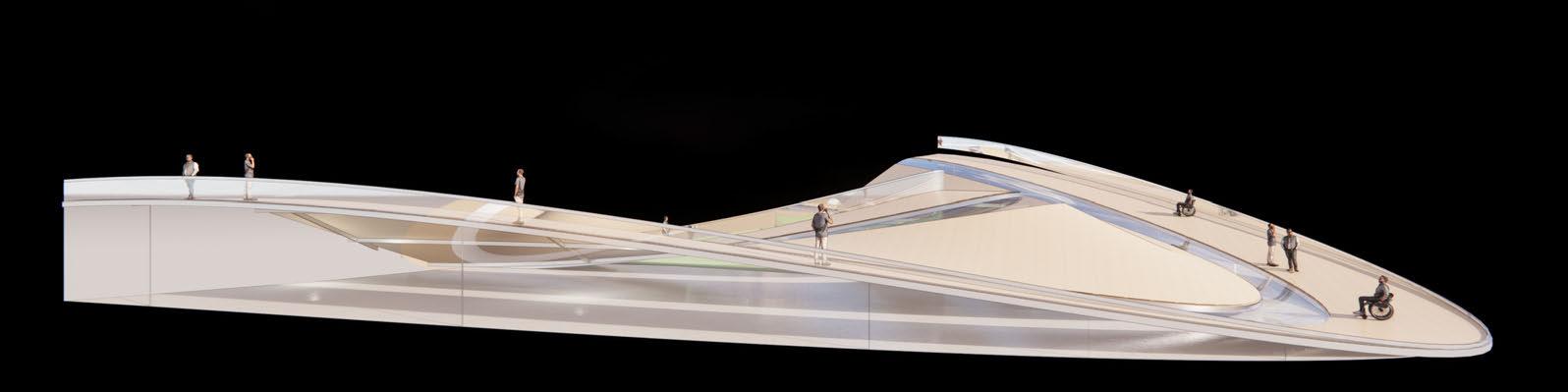
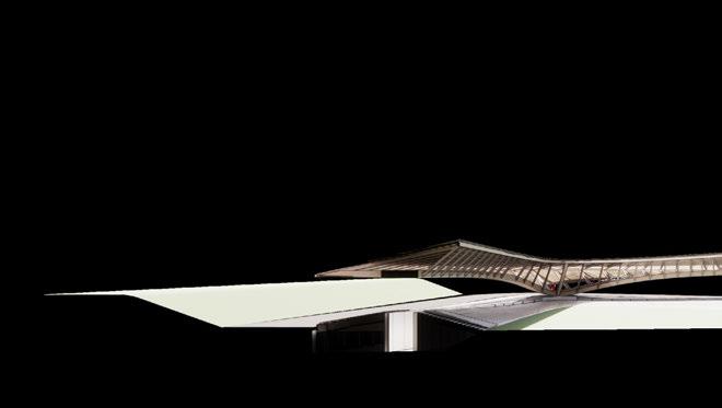
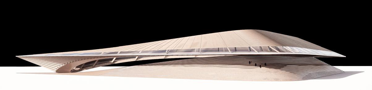
Distant Elevation View - Silhouette
Design Development
Grandstand seating for main straight with access to internal betting faciltiies.
Viewing bridge grandstand provides elevated view above the track.
Viewing gallery for VIP members of the Hypaer Derby. Balconies for track viewing and optimal raised viewing for the paddock.
THE HYPÆR DERBY
FINAL DRAWINGS
ARCHIE KOE
Final Drawings
CHICANE RIVER BOURNE VIEWING BRIDGE
PIT STOP
PARKING
CORNER-VIEWING LAKE
CORNER RUN-OFF
THE HYPÆR DERBY
STABLES
Internal exposed area. Robot horses parade be inspected before the racing starts and begin.
Viewing ga llery for VIP members of the Hypaer Derby. Balconies for track viewing and optimal raised viewing for the paddock.
2 - Paddock
1 - VIP Floating Timber Roof
Track dips below the entrance bridge to allow access to internal stadium.
parade around to
Underground workshop for ongoing repairs to the robot horses.
Underground betting facilities for online/mobile bets displayed on large screens with recordings of race.
5 - Track
4 - Engineering Workshop
3 - Subterranean Betting Facilities
Viewing gallery for VIP members of the Hypaer Balconies for track viewing and optimal raised for the paddock.
1 - VIP Floating Timber Roof
Track dips below the entrance bridge to allow access to internal stadium.
Internal exposed area. Robot horses parade around to be inspected before the racing starts and betting can begin.
Hypaer Derby. raised viewing
Underground betting facilities for online/mobile bets displayed on large screens with recordings of race.
4 - Track
2 - Paddock
3 - Subterranean Betting Facilities
HYBRID VIEWING
Viewing gallery for VIP members of the Hypaer Balconies for track viewing and optimal for the paddock.
1 - VIP Floating Timber Roof
Track dips below the entrance bridge to allow access to internal stadium.
Internal exposed area. Robot horses parade around to be inspected before the racing starts and betting can begin.
Hypaer Derby. raised viewing
Underground betting facilities for online/mobile bets displayed on large screens with recordings of race.
4 - Track
2 - Paddock
3 - Subterranean Betting Facilities
2
Final Drawings
Track dips below the entrance bridge to allow access to internal stadium.
Internal exposed area. Robot horses parade around to be inspected before the racing starts and betting can begin.
Viewing gallery for VIP members of the Hypaer Derby. Balconies for track viewing and optimal raised viewing for the paddock.
3 - Track
2 - Paddock
1 - VIP Floating Timber Roof
Final Drawings
Interior VIP circulation following primary catenary beam.
Robot horses navigate onto triangular bridge to allow sight-lines for everybody before betting.
Seating for standard tickets to view paddock before placing bets before race starts.
3 - Interior VIP Occupied Roof Walkway
2 - Elevated Paddock Walk
1 - Paddock Seating
SILHOUETTE
Final Drawings
Final Drawings
Natural urban park with coniferous and deciduous trees blocks sound to nearby residential houses.
beam. Grass paddock surface allows betters to walk around and get close to the robot horses.
Steel foundation is elevated so that the primary structure does not sit in water.
5 - Urban Park
- Paddock 3 - Foundation
TWILIGHT RACE
Final Drawings
N Track dips below the entrance bridge to allow access to internal stadium.
Track dips below the entrance bridge to allow acces to inernal stadium.
Track dips below the entrance bridge to allow acces to inernal stadium.
Track dips below the entrance bridge
inernal stadium.
Track
stadium.
Track
Internal exposed area. Robot horses parade around to be inspected before the racing starts and betting can begin.
Underground workshop for ongoing repairs to the robot horses.
Viewing gallery for VIP members of the Hypaer Derby. Balconies for track viewing and optimal raised viewing for the paddock.
Underground betting facilities for online/mobile bets displayed on large screens with recordings of race.
PLAN - VIP TIMBER PLAN
Internal exposed area. Robot horses parade around to be inspected before the racing starts and betting
Underground betting facilities for online/mobile bets displayed on large screens with recordings of race.
Track dips below the entrance bridge to allow access to internal stadium.
Track dips below the entrance bridge to allow acces to inernal stadium.
Track dips below the entrance bridge to allow acces to inernal stadium.
Track dips below the entrance bridge
inernal stadium.
Track
stadium.
Track
Underground workshop for ongoing repairs to the robot horses.
Viewing gallery for VIP members of the Hypaer Derby. Balconies for track viewing and optimal raised viewing for the paddock.
PLAN - SEATING PLAN
Track dips below the entrance bridge to allow access to internal stadium.
Track dips below the entrance bridge to allow acces to inernal stadium.
Track dips below the entrance bridge to allow acces to inernal stadium.
Track dips below the
inernal stadium.
Track
Track
Internal exposed area. Robot horses parade around to be inspected before the racing starts and betting
Underground workshop for ongoing repairs to the robot horses.
Viewing gallery for VIP members of the Hypaer Derby. Balconies for track viewing and optimal raised viewing for the paddock.
Underground betting facilities for online/mobile bets displayed on large screens with recordings of race.
PLAN - GROUND FLOOR PLAN
GENERAL ARRANGEMENTS GF (0.5M)
Track dips below the entrance bridge to allow access to internal stadium.
Track dips below the entrance bridge to allow acces to inernal stadium.
Track dips below the entrance bridge to allow acces to inernal stadium.
Track dips below the entrance bridge
inernal stadium.
Track
inernal stadium.
Track
Internal exposed area. Robot horses parade around to be inspected before the racing starts and betting
Underground workshop for ongoing repairs to the robot horses.
Viewing gallery for VIP members of the Hypaer Derby. Balconies for track viewing and optimal raised viewing for the paddock.
Underground betting facilities for online/mobile bets displayed on large screens with recordings of race.
5 - Track
PLAN - BASEMANT PLAN
Track dips below the entrance bridge to allow access to internal stadium.
Track dips below the entrance bridge to allow acces to inernal stadium.
Track dips below the entrance bridge to allow acces to inernal stadium.
Track dips below the entrance bridge to
inernal stadium.
Track
inernal stadium.
Track
stadium.
Internal exposed area. Robot horses parade around to be inspected before the racing starts and betting can begin.
Underground workshop for ongoing repairs to the robot horses.
Viewing gallery for VIP members of the Hypaer Derby. Balconies for track viewing and optimal raised viewing for the paddock.
Underground betting facilities for online/mobile bets displayed on large screens with recordings of race.
ELEVATION AA’ - SECTION AA’
APPENDIX
Viewing gallery for VIP members of the Hypaer Derby. Balconies for track viewing and optimal raised viewing for the
GENERAL ARRANGEMENTS
Underground workshop for ongoing repairs to the robot horses.
Underground betting facilities for online/mobile bets displayed on large screens with recordings of race.
Track dips below the entrance bridge to allow access to internal stadium.
Internal exposed area. Robot horses parade around to be inspected before the racing starts and betting can begin.
Grandstand seating to watch the main race events
paddock.
6 - Subterranean Betting Facilities
ELEVATION BB’ - ELEVATION CC’
APPENDIX
Viewing gallery for VIP members of the Hypaer Derby. Balconies for track viewing and optimal raised viewing for the paddock.
GENERAL ARRANGEMENTS
Underground workshop for ongoing repairs to the robot horses.
Internal
Grandstand seating to watch the main race events
Track dips below the entrance bridge to allow access to internal stadium.
Underground betting facilities for online/mobile bets displayed on large screens with recordings of race.
exposed area. Robot horses parade around to be inspected before the racing starts and betting can begin.
- Subterranean Betting Facilities
ELEVATION DD’ - SECTION DD’
APPENDIX
Viewing gallery for VIP members of the Hypaer Derby. Balconies for track viewing and optimal raised viewing for the
GENERAL ARRANGEMENTS
Underground workshop for ongoing repairs to the robot horses.
Grandstand seating to watch the main race events
Underground betting facilities for online/mobile bets displayed on large screens with recordings of race.
Track dips below the entrance bridge to allow access to internal stadium.
Internal exposed area. Robot horses parade around to be inspected before the racing starts and betting can begin.
paddock.
- Subterranean Betting Facilities
All work produced by Unit 14
Cover design by Charlie Harrishttps://www.ucl.ac.uk/bartlett/architecture
Copyright 2025 The Bartlett School of Architecture, UCL All rights reserved.
No part of this publication may be reproduced or transmitted in any form or by any means, electronic or mechanical, including photocopy, recording or any information storage and retrieval system without permission in writing from the publisher.
INVESTIGAIVE DOMAIN 2025
At the center of Unit 14’s academic exploration lies Buckminster Fuller’s ideal of the ‘The Comprehensive Designer’, a master-builder that follows Renaissance principles and a holistic approach. Fuller referred to this ideal of the designer as somebody who is capable of comprehending the ‘integrateable significance’ of specialised findings and is able to realise and coordinate the commonwealth potentials of these discoveries while not disappearing into a career of expertise. Like Fuller, we are opportunists in search of new ideas and their benefits via architectural synthesis. As such Unit 14 is a test bed for exploration and innovation, examining the role of the architect in an environment of continuous change. We are in search of the new, leveraging technologies, workflows and modes of production seen in disciplines outside our own. We test ideas systematically by means of digital as well as physical drawings, models and prototypes. Our work evolves around technological speculation with a research-driven core, generating momentum through astute synthesis. Our propositions are ultimately made through the design of buildings and through the in-depth consideration of structural formation and tectonic. This, coupled with a strong research ethos, will generate new and unprecedented, one day viable and spectacular proposals. They will be beautiful because of their intelligence - extraordinary findings and the artful integration of those into architecture.
The focus of this year’s work evolves around the intrinsic chance and professional desire for creative and systematic investigation. The explorative and intellectual process of iterative learning through informed experiment, catalysed by potent discoveries and ultimately seeking an architectural application. An intensely investigative approach enables the architect’s fundamental agency and core competency of the profession to anticipate the future as the result of the highest degree of synthesis of the observed underlying principles underpinned by strong research. Constructional logic, spatial innovation, typological organisation, environmental and structural performance are all negotiated in a highly iterative process driven by intense architectural investigation. Through the deep understanding of principles, we will generate highly developed architectural systems of unencountered intensity where spatial organisation arises as a result of sets of mutual interactions. Observation as well as re-examination of past and contemporary civilisational developments will enable us to project near future scenarios and position ourselves as avant-garde in the process of designing a comprehensive vision for the forthcoming. The projects will take shape as research based, imaginative architectural visions driven by speculation.