TRAIN STATION KATOWICE GŁÓWNE

-
PACH -
5 @unit14_ucl UNIT Y5 KP
KACPER
YEAR
All work produced by Unit 14
-
www.bartlett.ucl.ac.uk/architecture
Copyright 2021
The Bartlett School of Architecture, UCL All rights reserved.

No part of this publication may be reproduced or transmitted in any form or by any means, electronic or mechanical, including photocopy, recording or any information storage and retrieval system without permission in writing from the publisher.

@unit14_ucl
 Cover design by Charlie Harris
TRAIN STATION KATOWICE G ŁÓ WNE
KATOWICE, POLAND


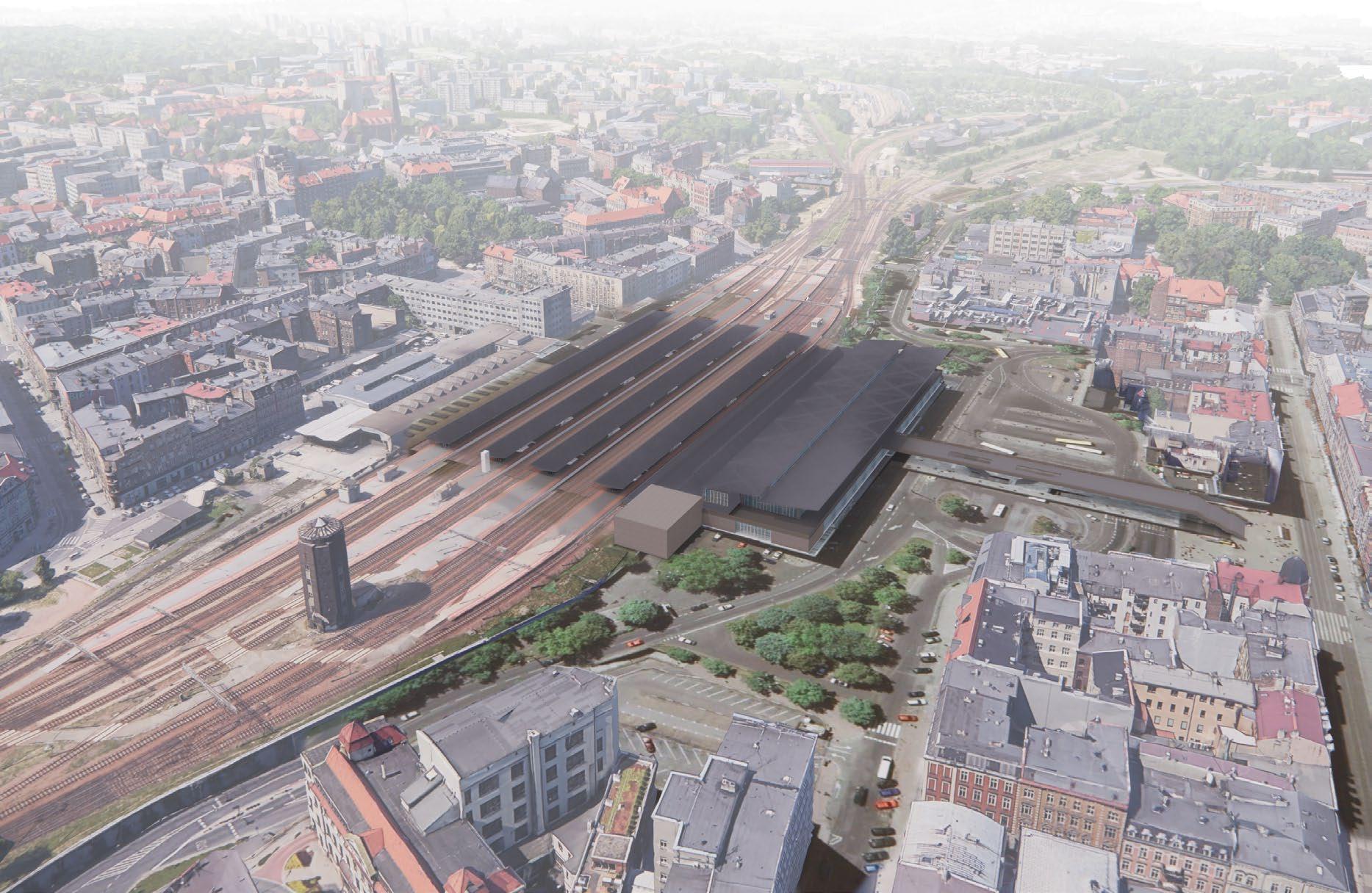
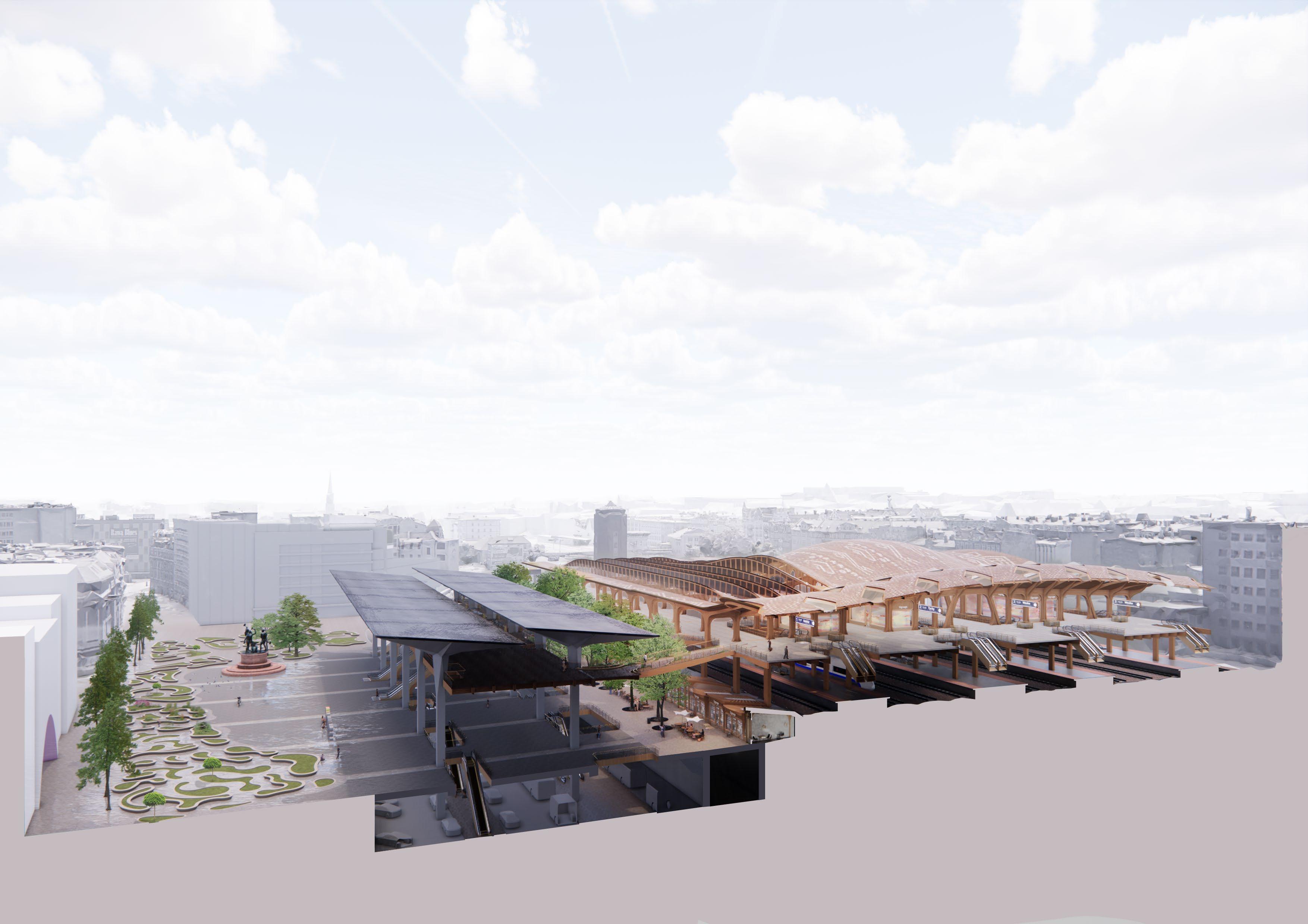
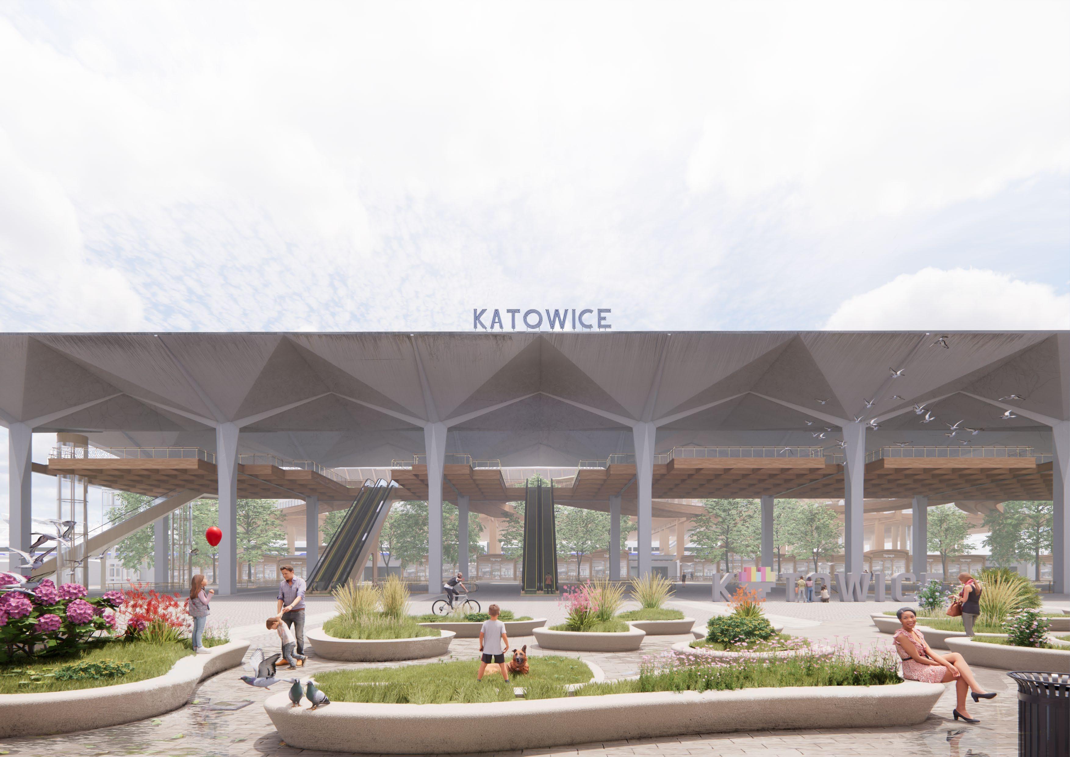
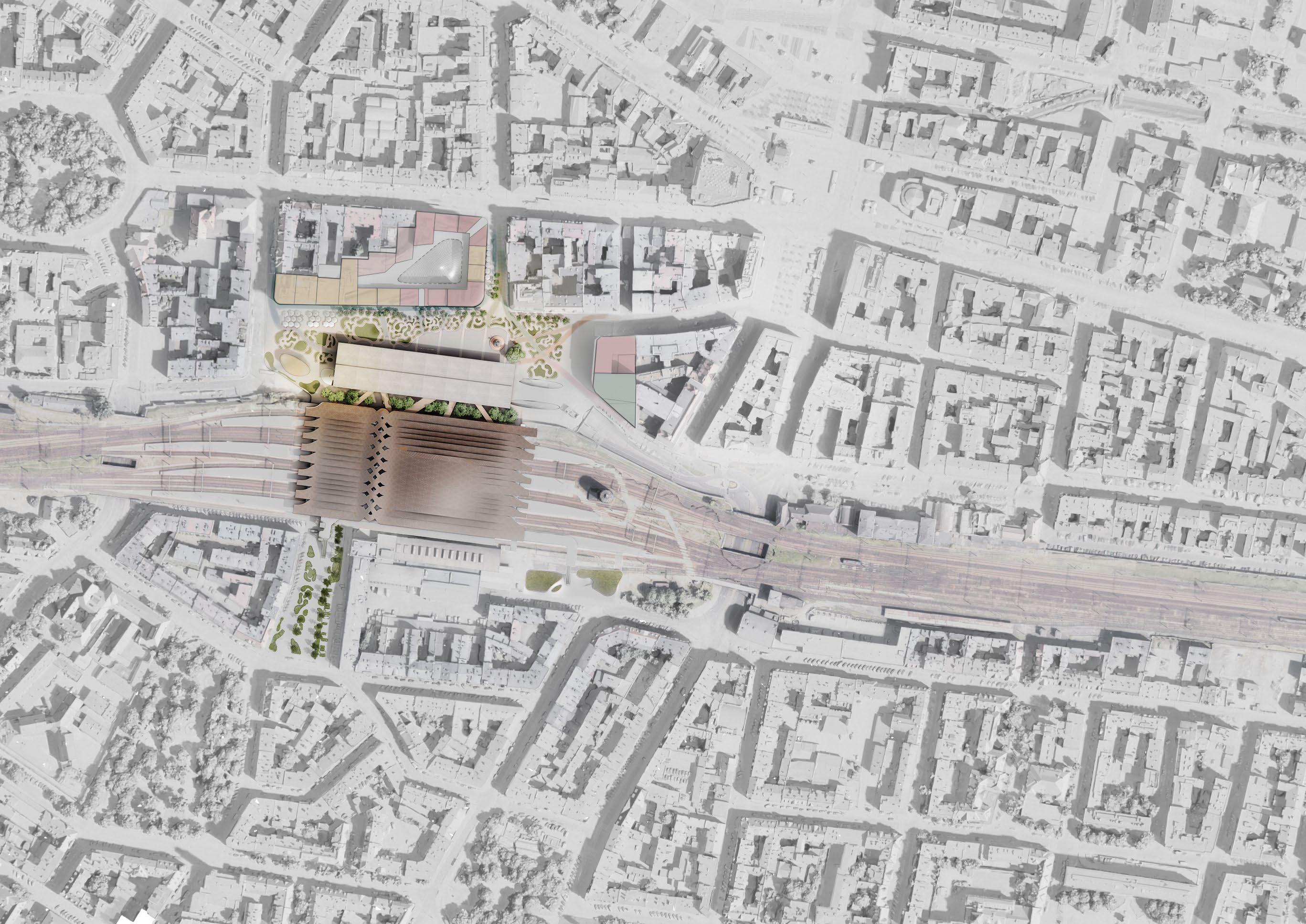
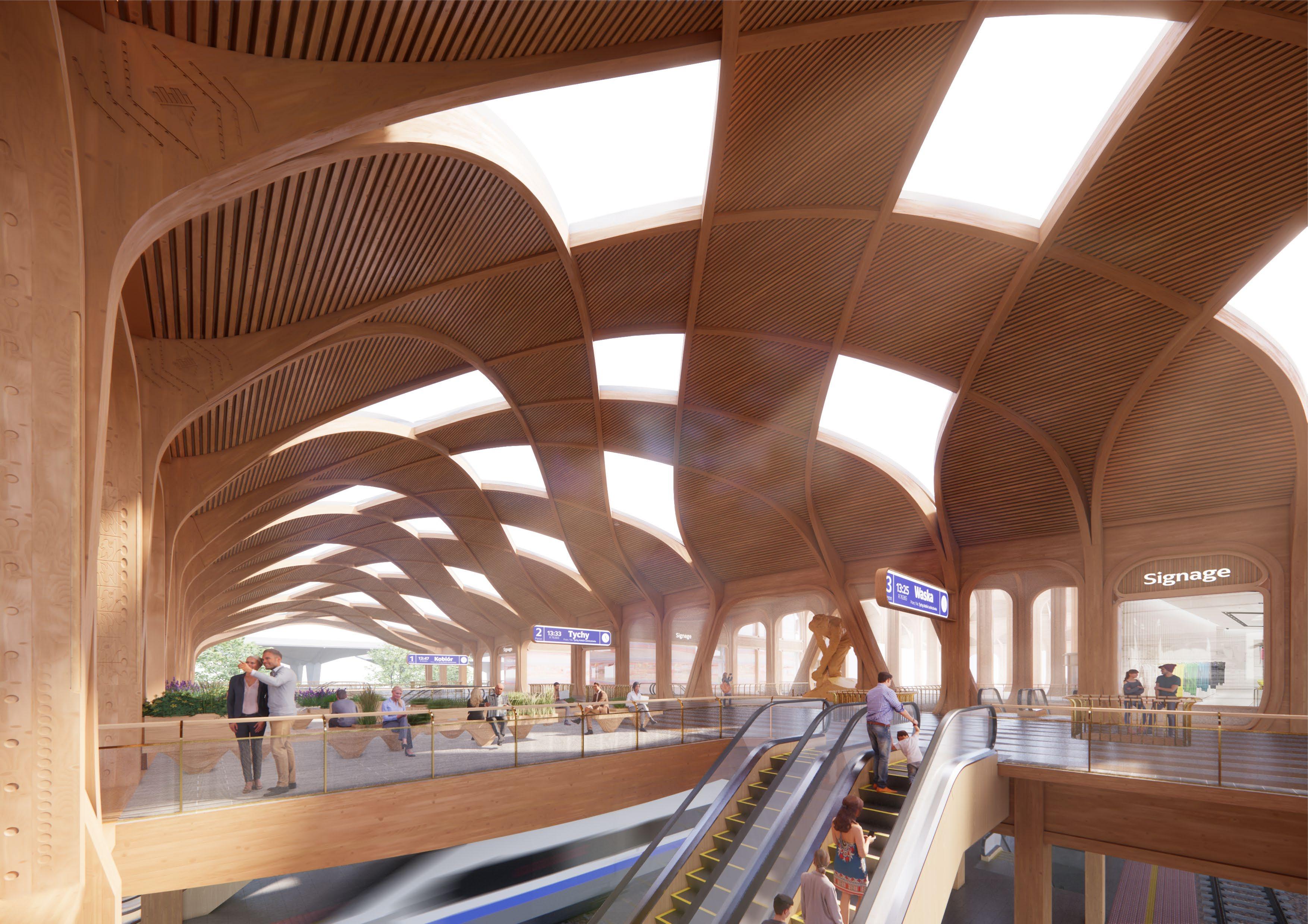
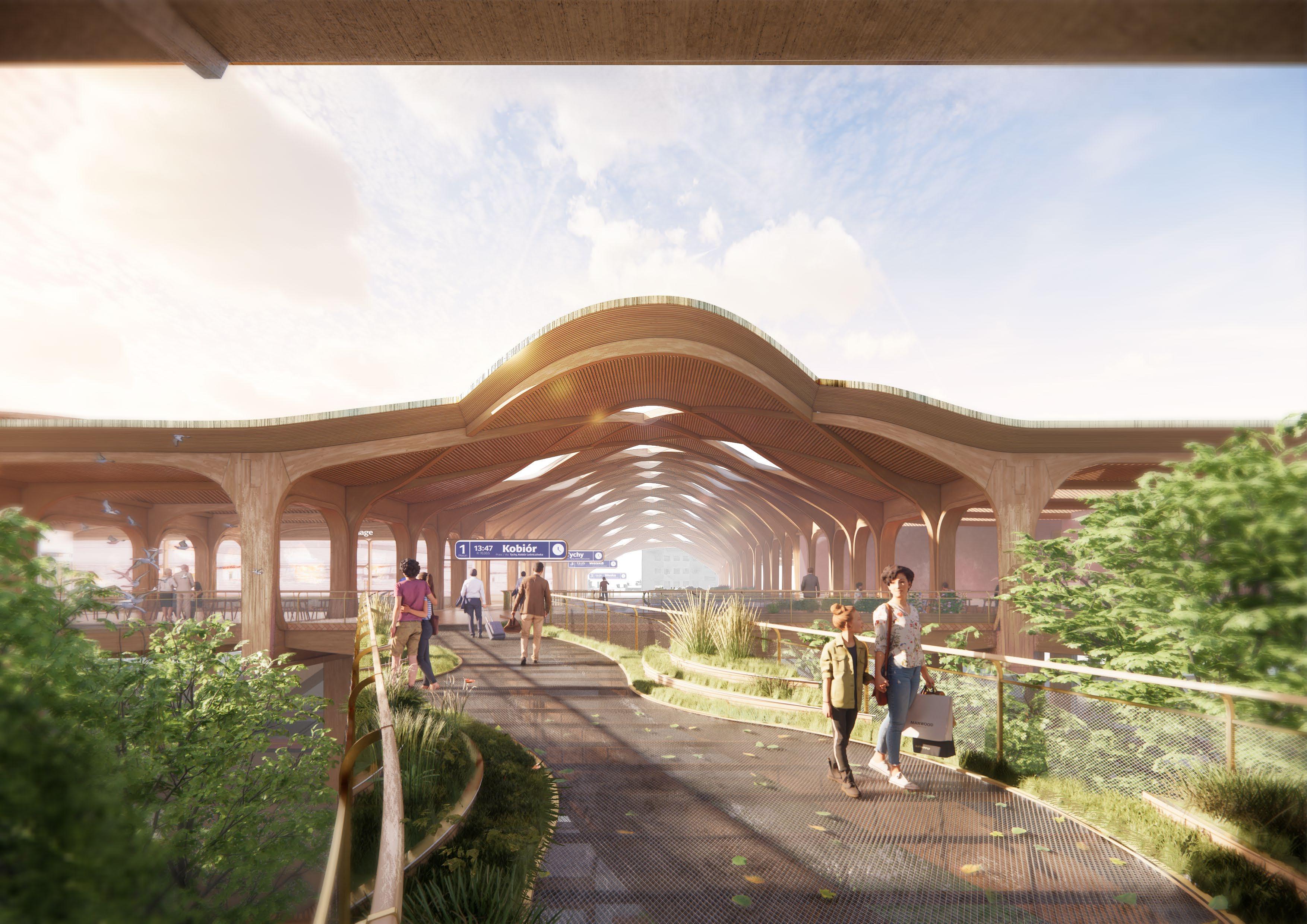
This project proposes an alternative to the redesign of Katowice Główne train station, Poland, which was completed in 2012. The new station is more considered of its historically sensitive context and provides better pedestrian connectivity across the railway. The bus station and the road are moved underground to pedestrianise the newly created public realm. The station forecourt is in front of the 1970s canopies, which the new proposal retains. The building redefines the image of the city by making Katowice a green and pedestrian friendly city that pioneers sustainability through public infrastructure.
KACPER PACH YEAR 5
Y5 KP
pach.kcpr@gmail.com @unit14_ucl
Chapter 1 - IN tr ODUC t ION
1.1. PROJECT LOCATION
Zag ę szczenie ludno ś ci (os/k m 2) Population dens ty (person/k m 2) G
255
1
EUROPEAN METROPOLISES WITH INDUSTRIAL PAST Katowice Area (km ² ) Population (million) Population density ( person/km 2) GDP (bln) GDP per capita 1 276 2,55 2 001 € 62,00 € 24 282 Area (km ² ) Population (million) Population density ( person/km 2) GDP (bln) GDP per capita 5 427 1,20 222 € 28,16 € 23 4 00 OSTRAVA (MORAVIAN-SILESIAN REGION) Area (km ² ) Population ( million) Population density ( person/km 2) GDP (bln) GDP per capita 2 500 2,24 896 € 35,66 € 14 64 0 12 330 4,53 € 260,53 METROPOLIS GZM Upper Silesia region Area (km ² ) Population (million) Population density ( person/km 2) GDP (bln) GDP per capita 4 4 35 5,11 1 153 € 162,60 € 31 810 2 3 1 RUHR REGIONALVERBAND M A NC HE S T E R ME T R O P O L I S 4
PKB (mld) G DP (bln) PKB per c apita
DP per c apita
2 - I NTRO du CTION
Powierzchnia (k m ² ) Area (k m ² ) Ludno ść (mln) Population (million)
€ 163 80 € 30 588
4 268 5 36
project – intell gent city transp or t O B S Z A R M E T R O P O LI TA L N Y BA R CE L O N Y A R E A M E T R O P O LI TAN BA R C E L O N A M E T R O P O LI TA N A R E A A R E A M E T R O P O L I TAN A D 3 1 2 1 3 Upper Silesia Historical Silesia GórnośląskoZagłębiowska Metropolia
Zalety i sukcesy Metropolii Advantages and successes of m etropolis Transp or t, pr ze mys ł sa m ocho do w y, fa r m aceutyczny, che miczny; 4 najba rdziej inno wacyjne mi asto w Europie w g Innovation Cit es Index by 2thinkno w; 3 miejsce w Europie po d k ą te m atrakcyjno ś ci zak ł adani a sta r tup ó w w g Sta r tUp Heatm ap Europ e 2019; 3 4% eksp or tu Hiszpani i p ocho dzi z Kata loni i C M obILE project – intel igentny transp or t miejski / Transp or t autom otive pha r m aceutica l and che mica l industr ies 4th m ost innovative city in Europ e according to the nnovation Cit es ndex by 2thinkno w; 3rd pl ace in Europ e in ter m s of the attractiveness of establ ishing sta r tups according to Sta r tUp Heatm ap Europ e 2019; 3 4% of Spa ins exp or ts co m e f ro m Cata loni a C M obILE
Poland
1.2. WHAT IS THE PROJECT ABO u T
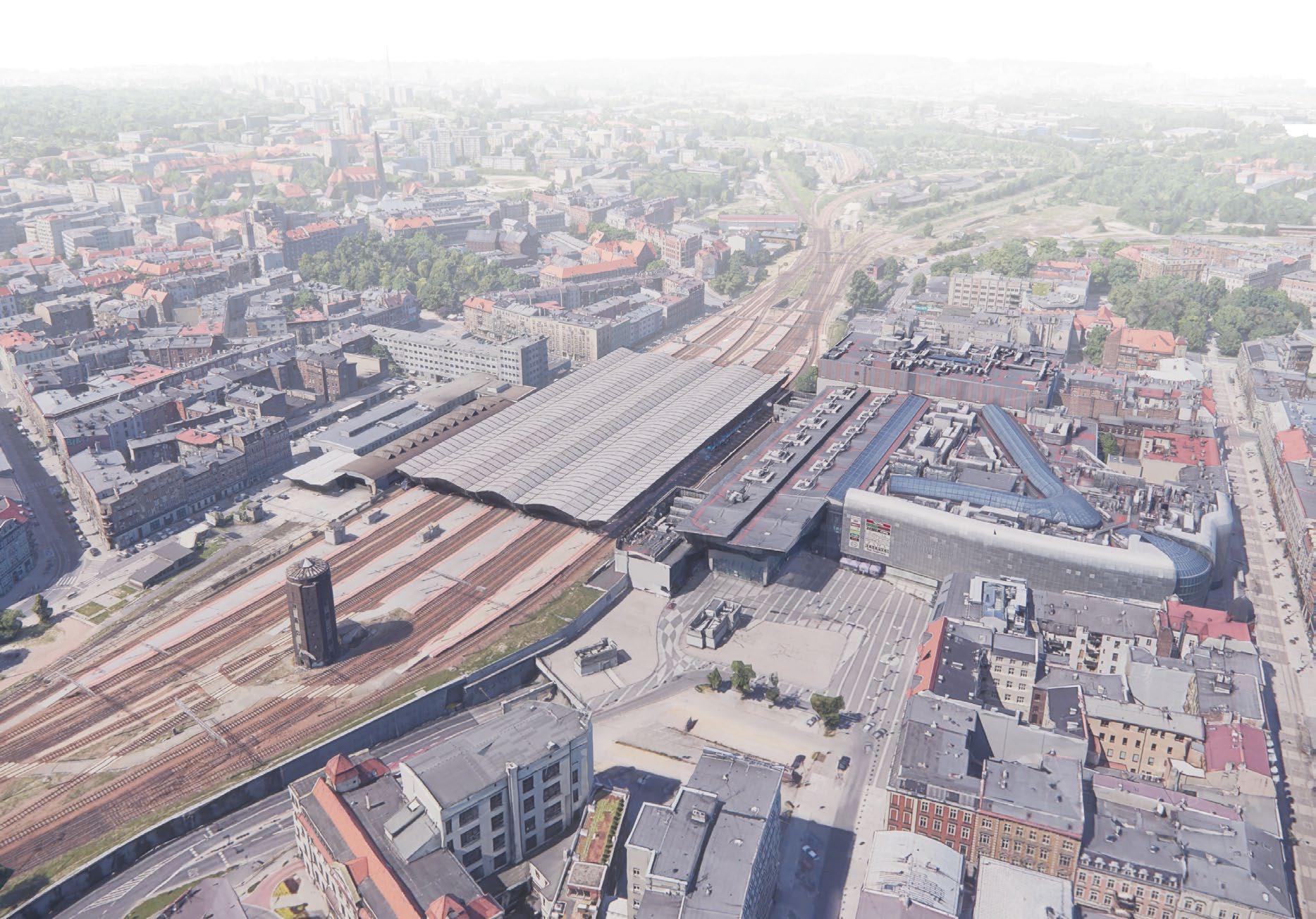
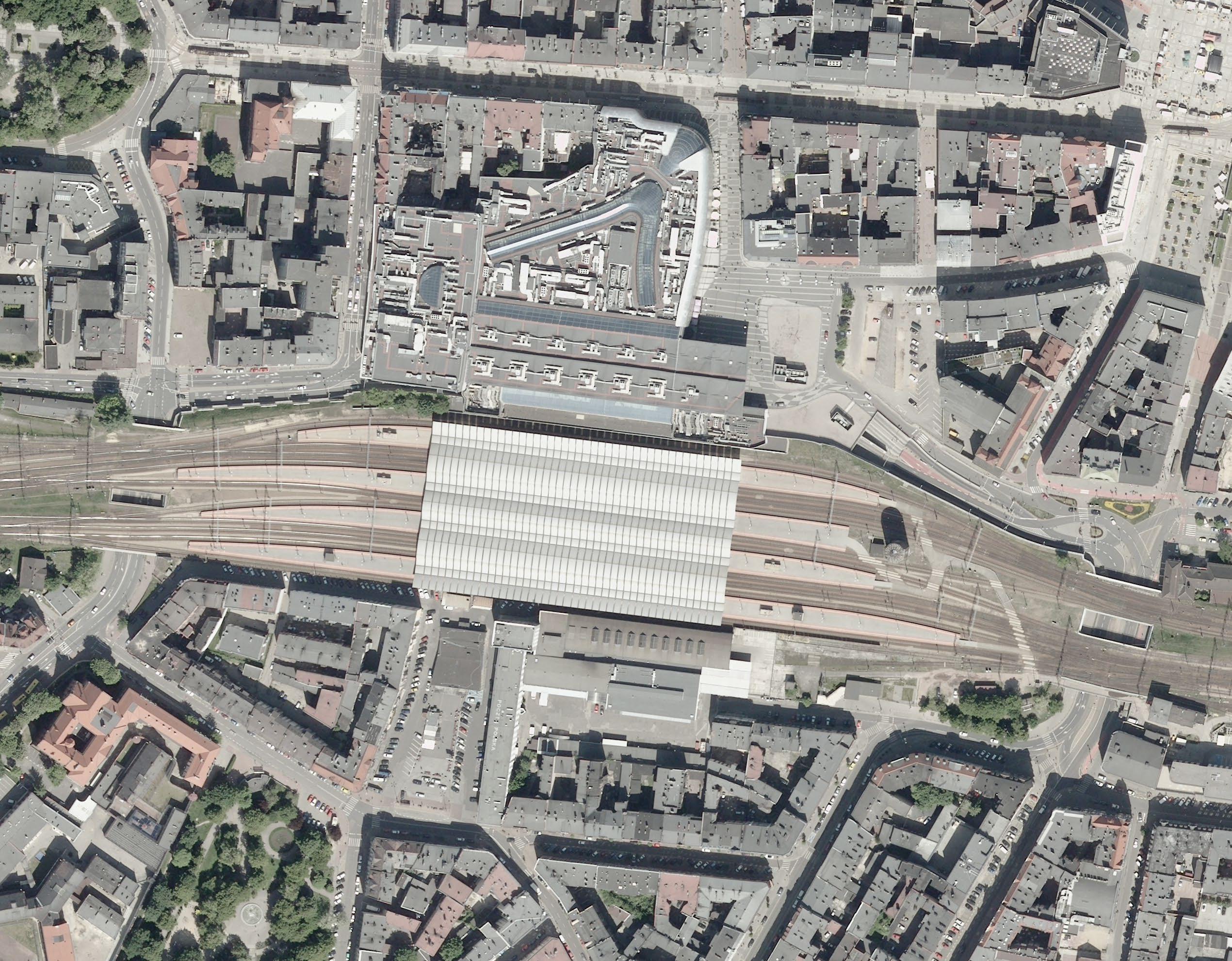
This project proposes an alternative to the design of Katowice train station from 2012. Train station with shopping mall erected in 2012
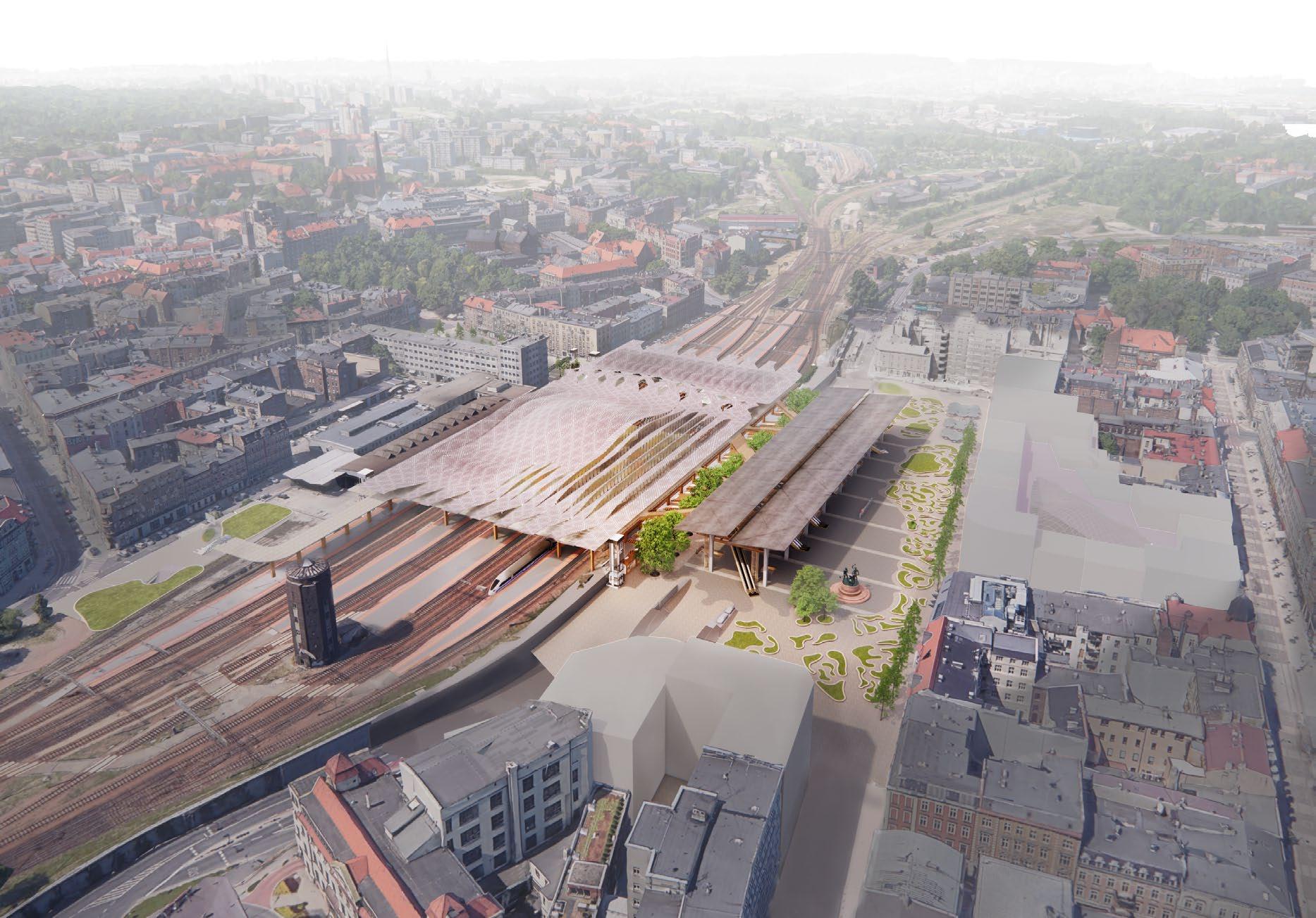
Proposed alternative design
3 AN A D
L O N A D E BA R CE L O N A
E BA R CE
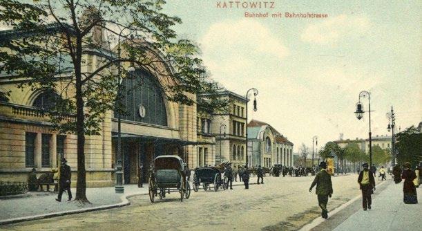
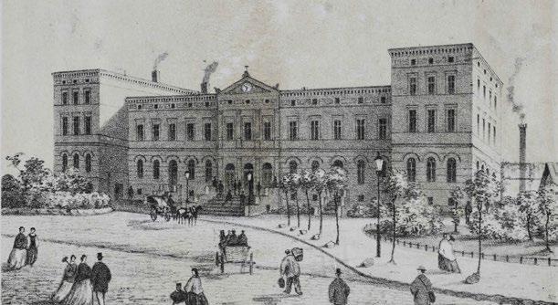
1.3. HISTORY
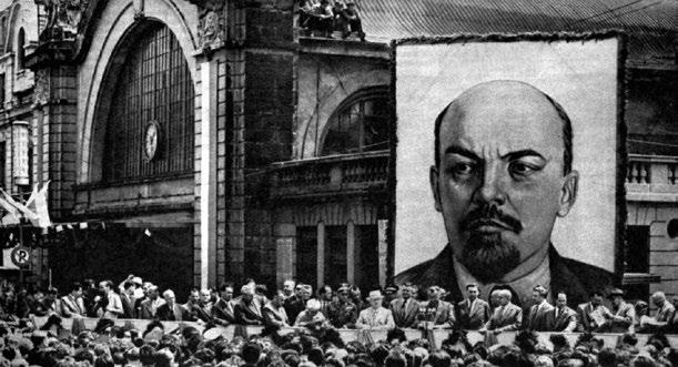
Station’s names
Kattowitz (1846–1909), (1939–1943)
Kattowitz Staatsbahnhof (1910–1922)
Kattowitz Hauptbahnhof (1944–1945)
Stalinogród (1953–1955)
Katowice Główne (1975–1976)

4 - I NTRO du CTION
1859 1906 1908 early 20th C. early
early
20th C.
20th C.
19-20TH c.
1984
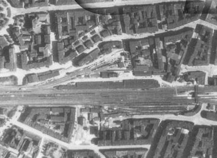
OLD STATION - KATTOWITZ HAUPTBAHNHOF
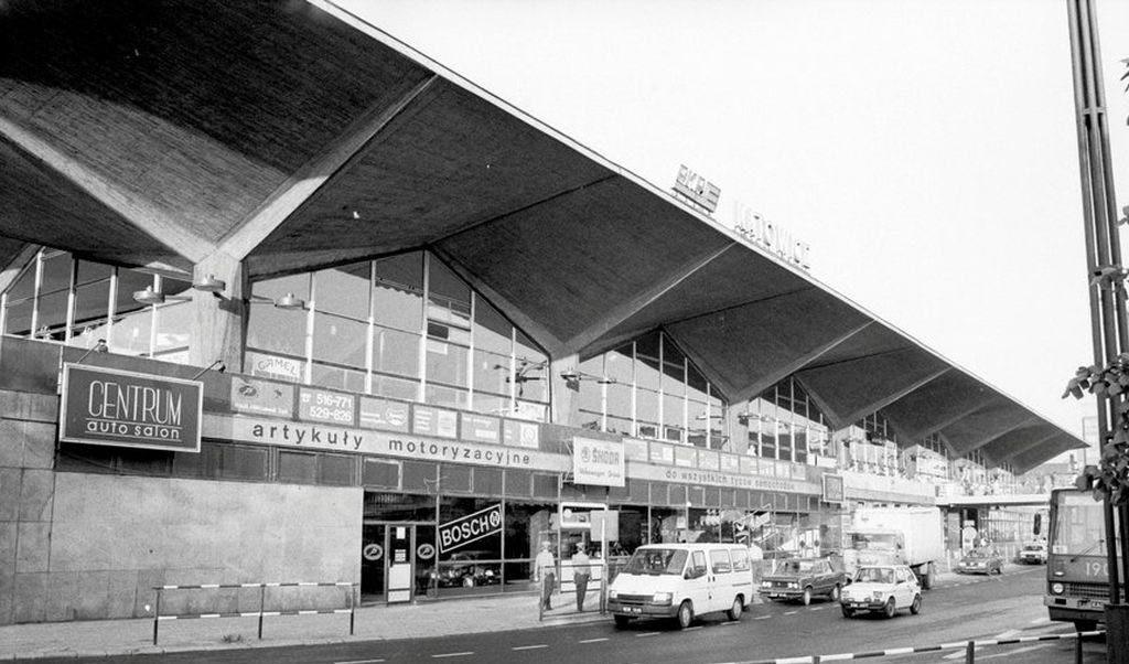
‘70S NEW BRUTALISE TRAIN STATION - STALINOGRÓD
Second station building, 1864-6 Art Noveau expansion, 1906-11 During the visit of Khrushchev, 1959
1944 2009
COAL DROP DEPOT ON THE SITE
Demolished in 1960s
The urban fabric that the proposed ‘mimics’. Demolished in 1960s
Soviet urban planners demolished 60 000 sqm of old town
This mistake happened In the context of the dangerous ideas of cleansing of modernism and of 20thc. in general
NEW STATION IS RE-LOCATED IN ‘70 s
5
1944 2009
KATTOWITZ HAUPTBAHNHOF IS FURTHER EAST - COAL DROP FACILITIES
6 - I NTRO du CTION
STATION STALINOGRÓD - A LOT OF DEMOLITIONS
2012 2012
KATOWICE GŁÓWNE - NEW STATION WITH SHOPPING MALL
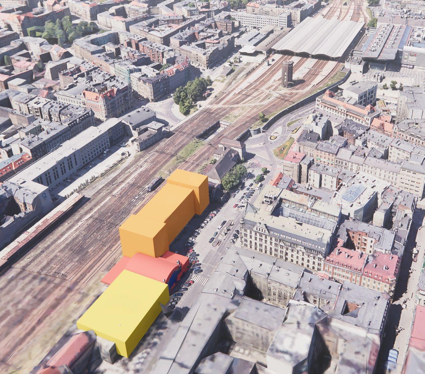
SPECULATIVE ALTERNATIVE DESIGN - STARTING POINT
7
Partial demolition of Soviet’s Station Brutalist canopy is retained
This 2012 solution is inconsiderate of the historical old town, urban fabric and the city’s image.
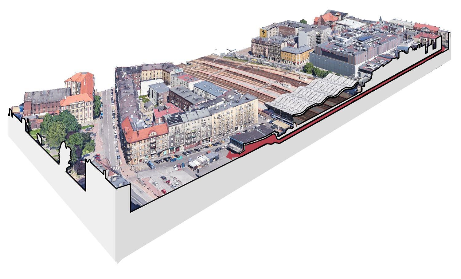
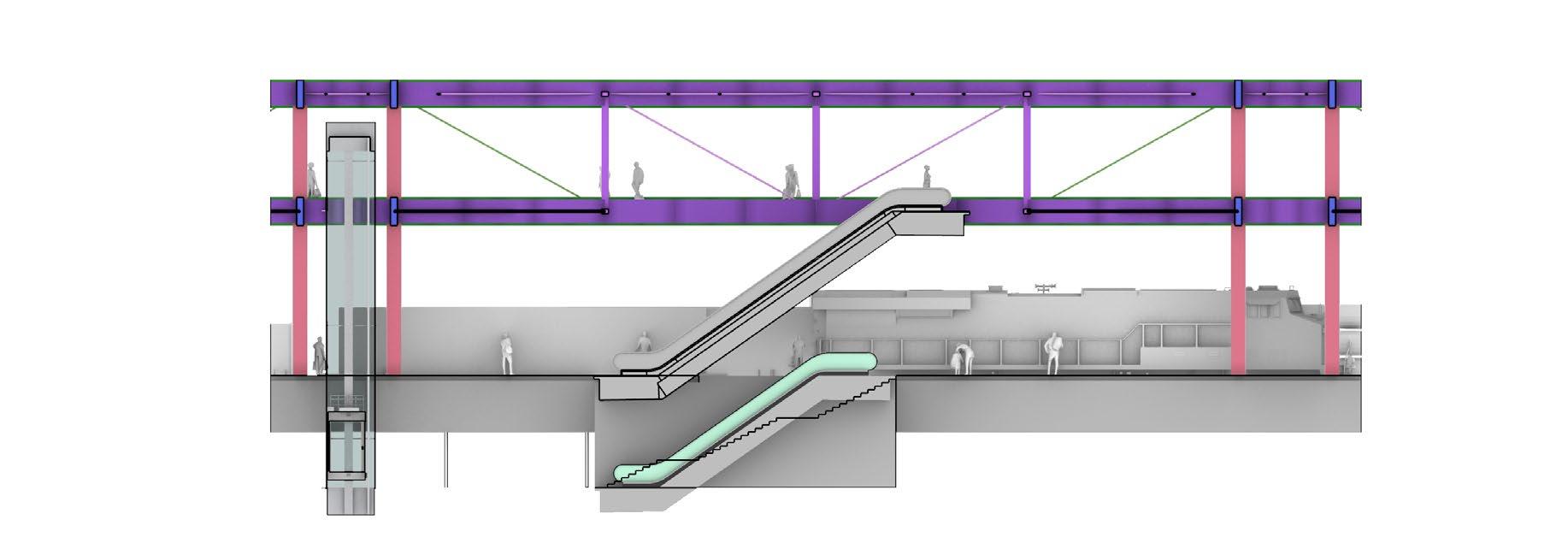
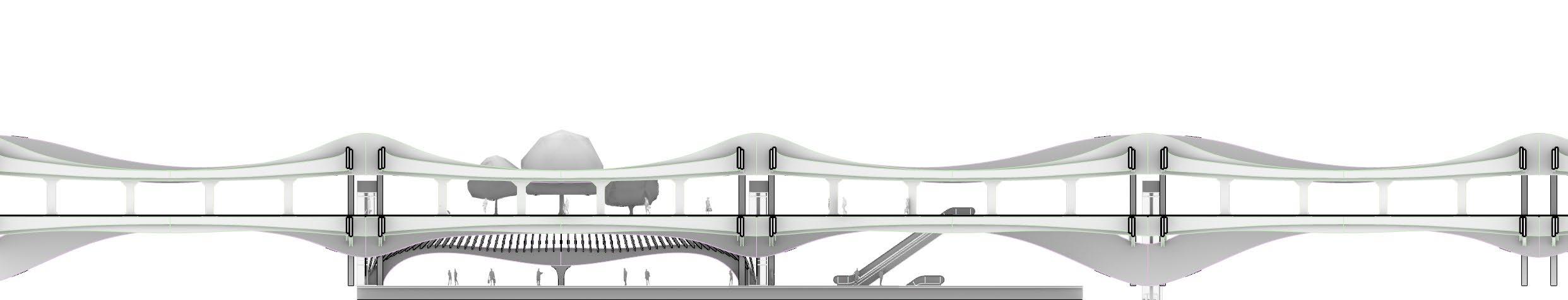
Section AA 1:1000 @A2 - Year 2009
South East Ticket hall
Section AA 1:1000 @A2 - Year 2012
Section AA 1:1000 @A2 - Year 2012 - New proposal
Tunnel - access to platforms 2012 2012
Elevating and extending the urban fabric
Section BB 1:1000 @A2 - Year 2012 - New proposal
Section AA 1:1000 @A2 - Year 2012 - New proposal
8 - I NTRO du CTION
2012 FInal Proposal
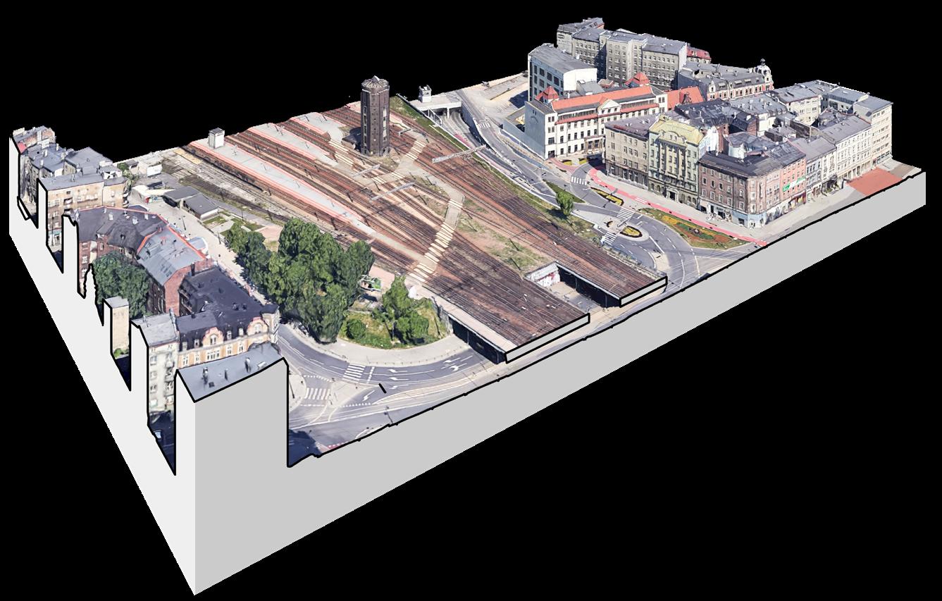
2009
Ticket halll Bus Station with elevated platform for access to station
Ticket halll, below parking
Shopping mall
Bus station under ground Canopies
Filling -in the gap in urban grid


Gradient 1:40 Gradient 1:40 9 A A B B
Extending the street over railway
 *Based on Existing 2012 Station III
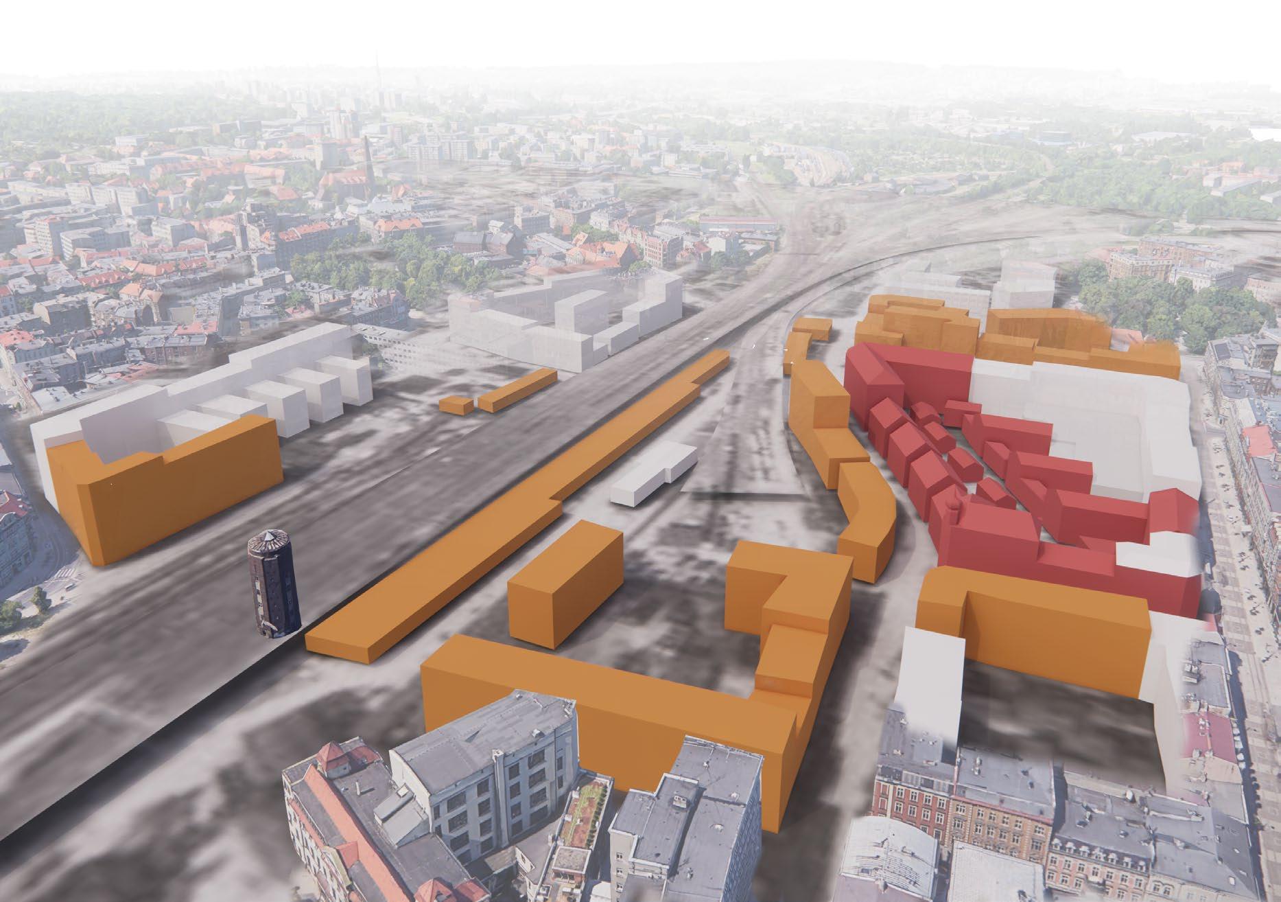
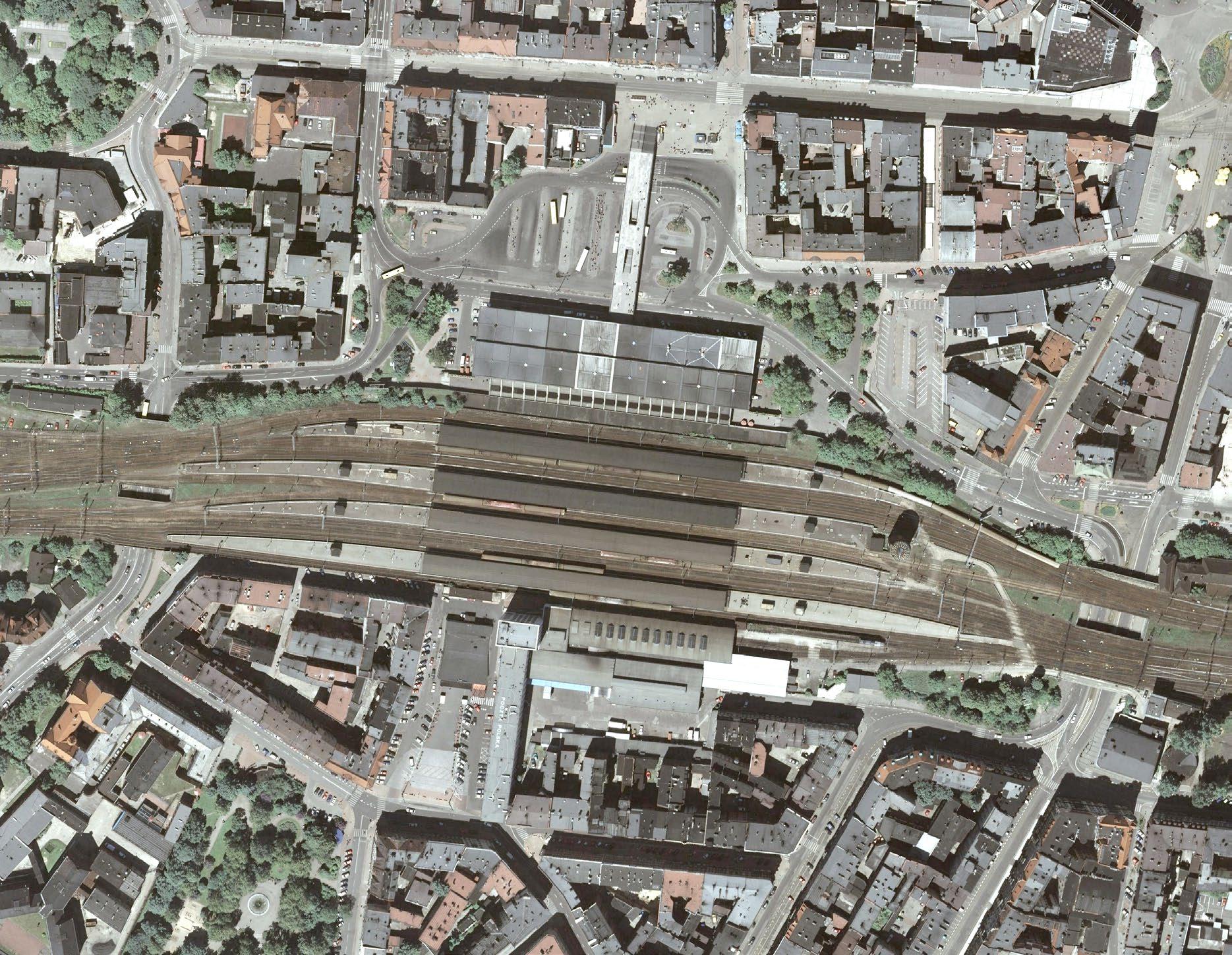
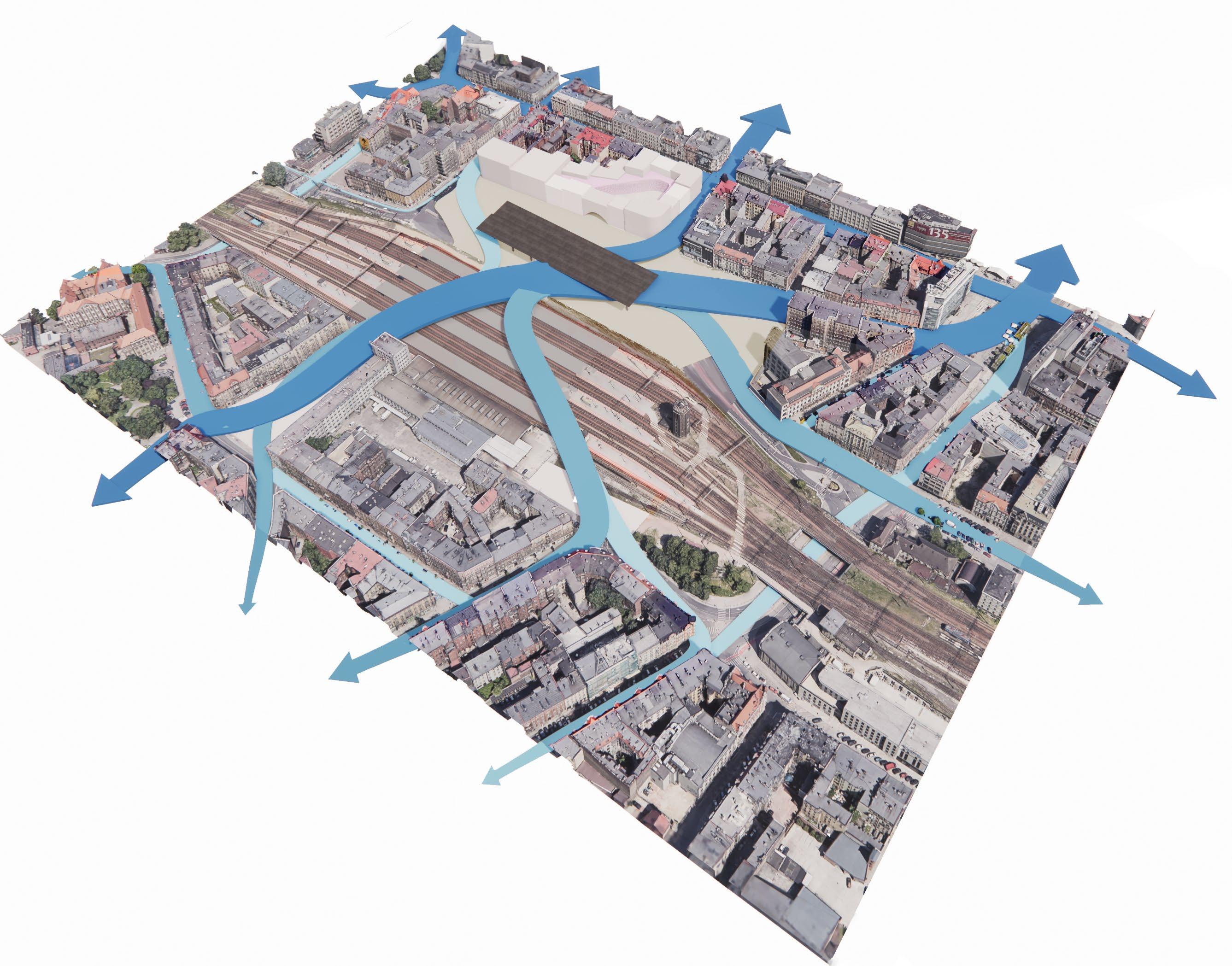
The city has been built around the railway tracks. It has been split since it conception. The city has developed due to railway but has to grow around it. Then Post war urban planning caused further divisions. This project addresses this division by proposing to extend the urban fabric over the railway - which is different to just a pedestrian bridge.
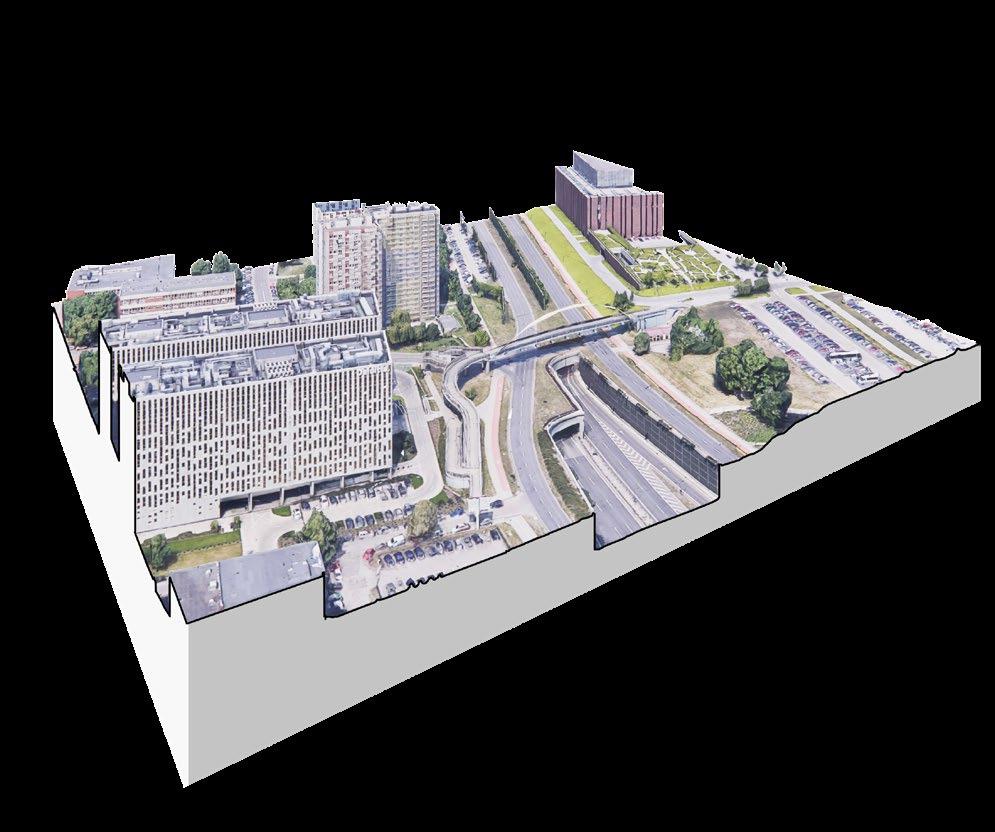
Pedestrian Bridge
Failed connectivity solution. All it connects are two carparks. No pedestrians to be seen.
Underpass
Car centred design with 2 m wide pavement without any greenery buffer from a very busy road.
Tunnel *BasedonExisting2012StationIII
Proposed New Approach to North-South Connectivity Problem
Over better than under Section Shows the city of 2010, before the Shopping mall development
11 railway 1:40 Gradient
1.4. THE d IVI d E d CITY
1.
Chapter 2 - the pr O p OS a L 2.1. d ESIGN ELEMENTS
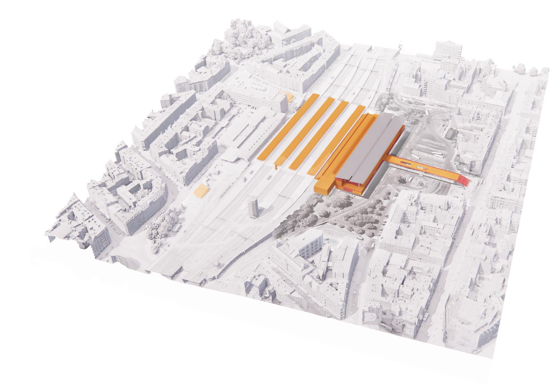
Preserving the Canopies

Only the canopies, platforms and underpasses are retained
Demolished
Ground Level was dominated by asphalt and vehicles
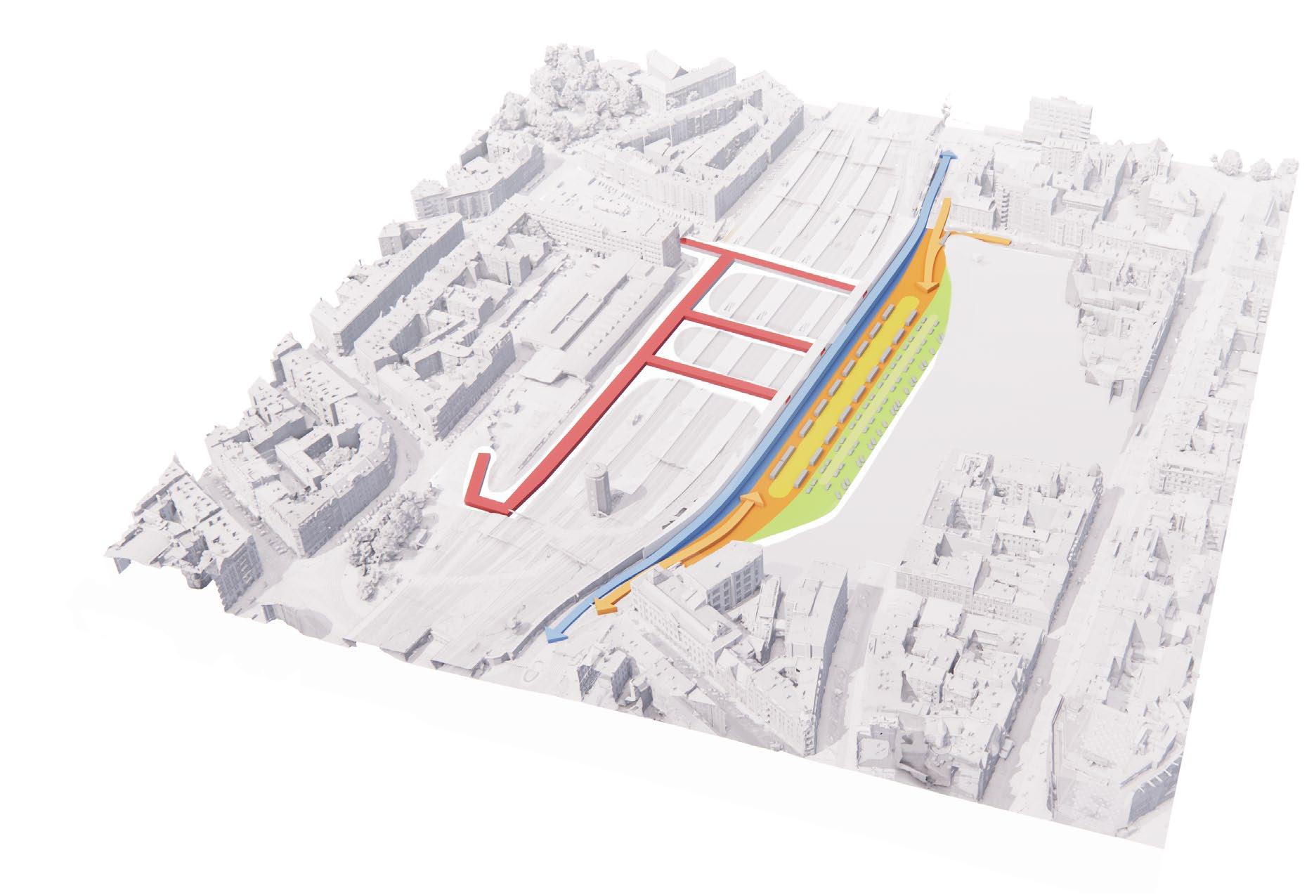
2. Underground Connectivity
Relocation of the Bus Station underground
Taxi and 3min ‘Kiss and Goodbye’ Parking
Existing tunnels retained New underground connection for cars. This allows for greater pedestrianisation of the public spaces in front of the station
12 - I NTRO du CTION
3. Urban Fix
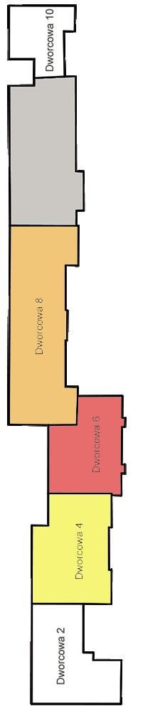
New Townhouses with high street shopping and a shopping arcade
Completing the urban block with a new building
New public space with a slope up to 1:30 gradient
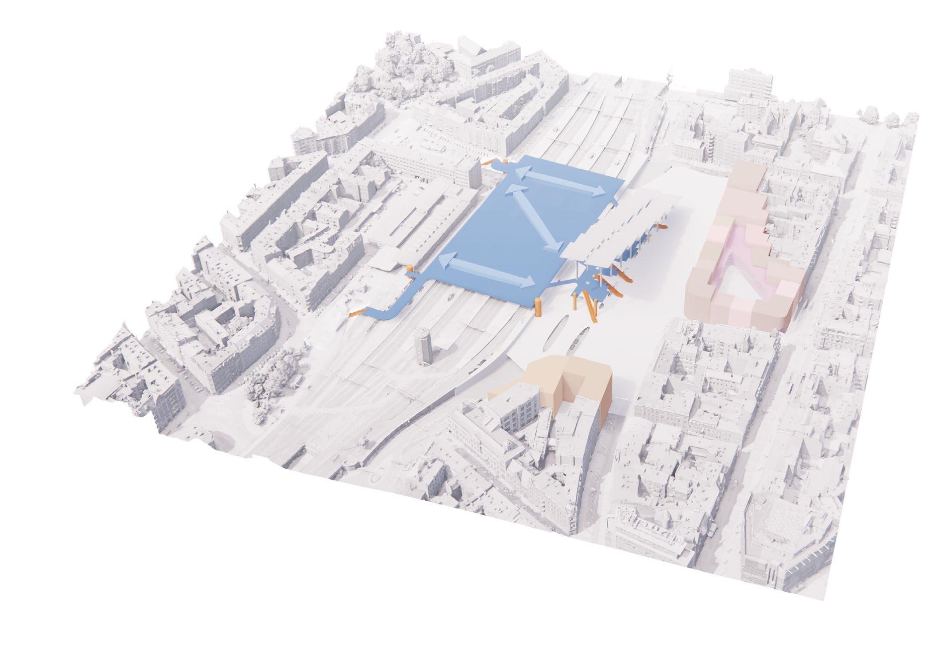
Providing quality pedestrian access across the railway
Kiss and Goodbye - No
and Goodbye - No Kisses above 3 min.!
Taxi lane Stop E2
Kisses
Taxi lane Taxi lane Stop D2 Stop B2 Taxi lane
Stop F2 Stop G2 Stop C2 Stop A2 Stop B1 Stop D1 Stop I2 Stop E1 Stop G1 Stop A1 Stop C1 Stop H2 Stop F1 13
above 3 min.!
Kiss
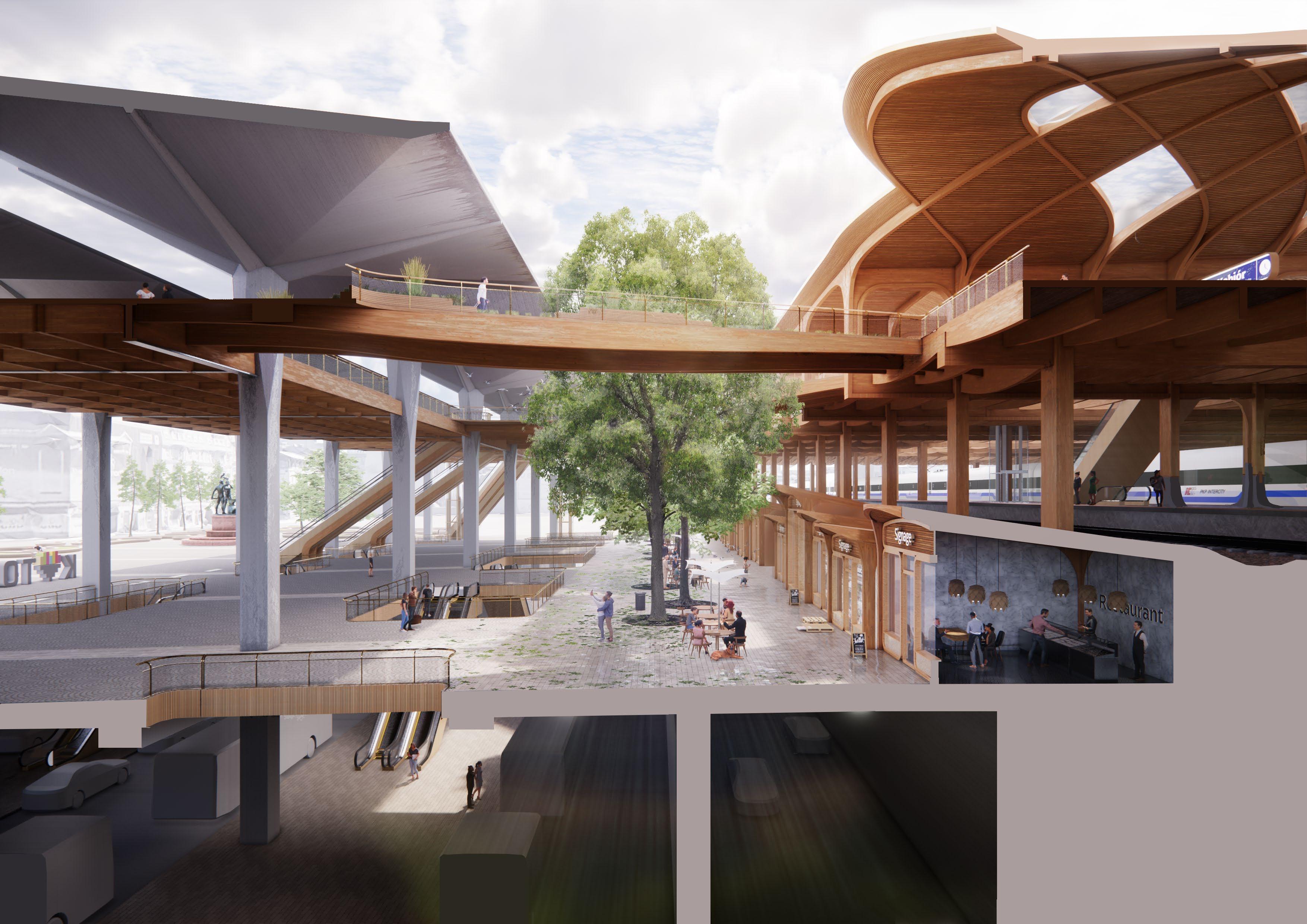
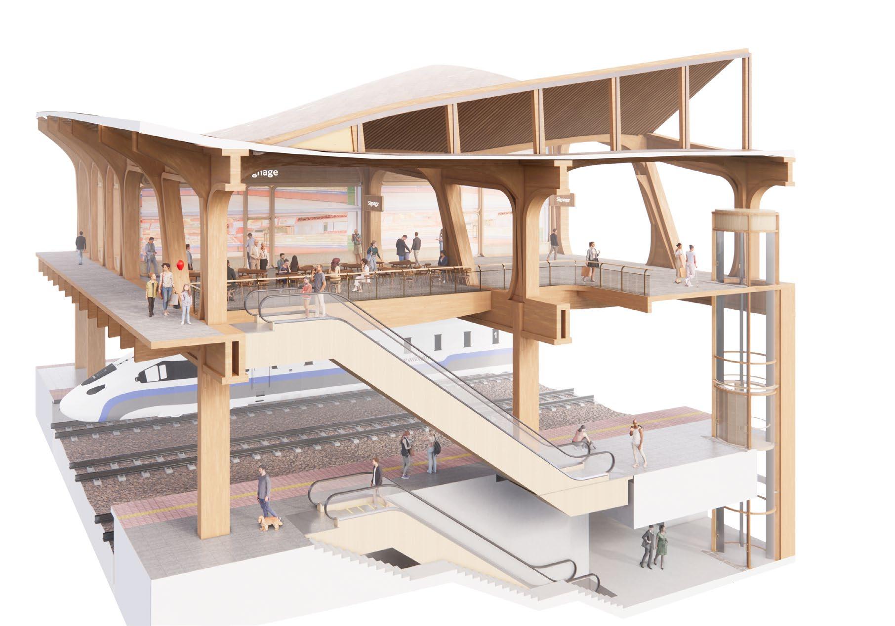
Elevated urban streets
Elevated boulevard has direct access to all platforms
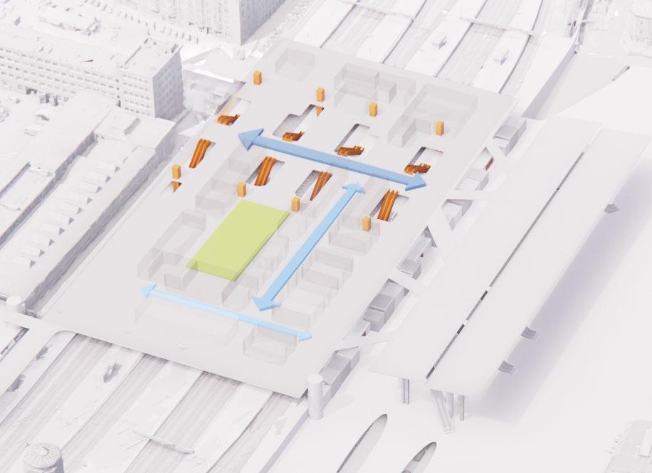
Shopping Arcade is the secondary street
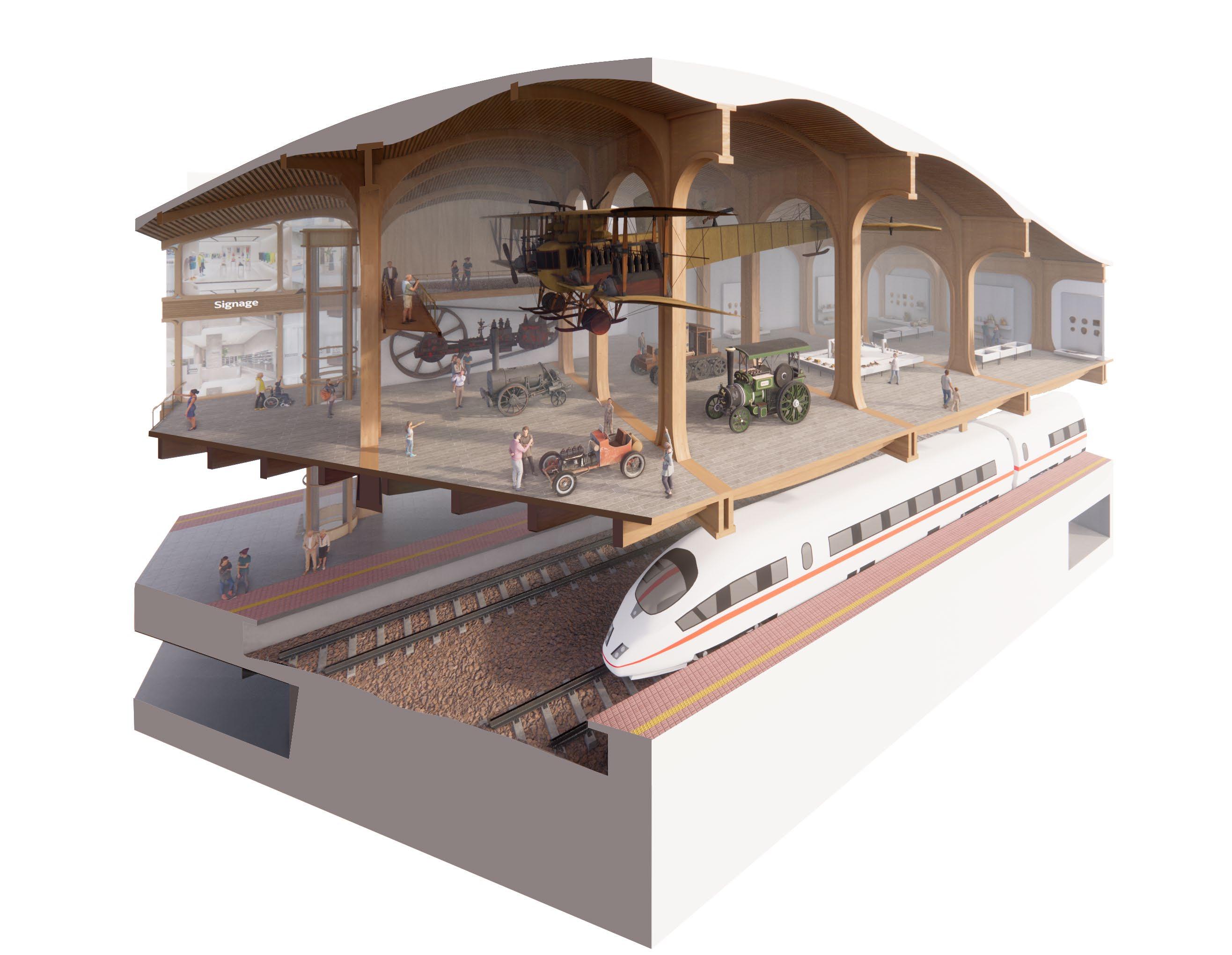
The Boulevard opens to courtyard with museum
Vertical circulation
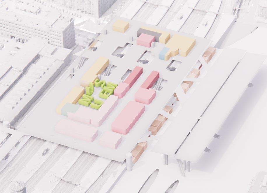
Program among streets
Food and Beverage
Tickets
Museum
Office
Primary Retail
Secondary Retail
Tertiary Retail
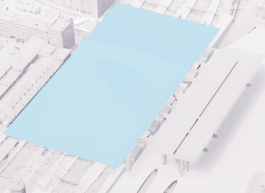
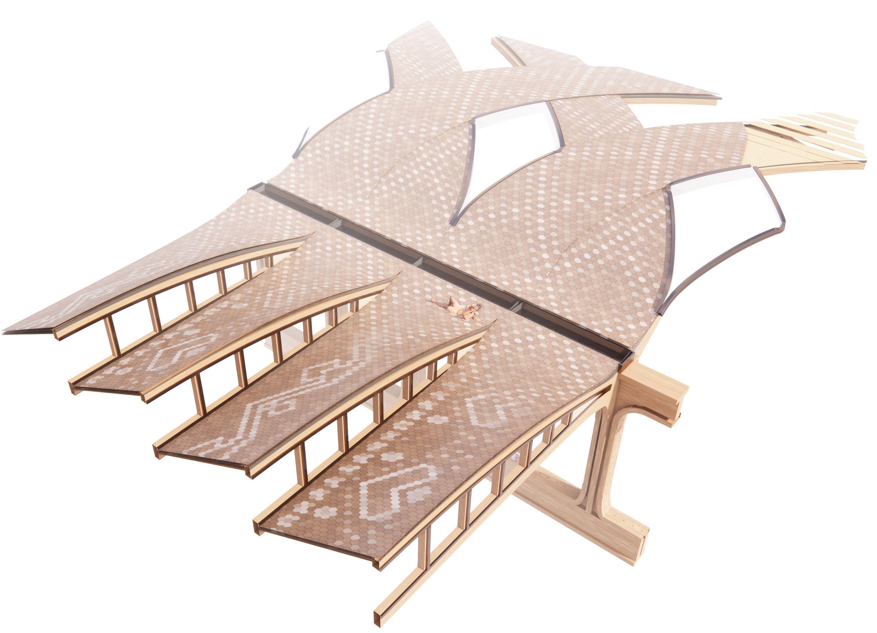
Program drapped with roof
Roof
14 - P ROPOSAL
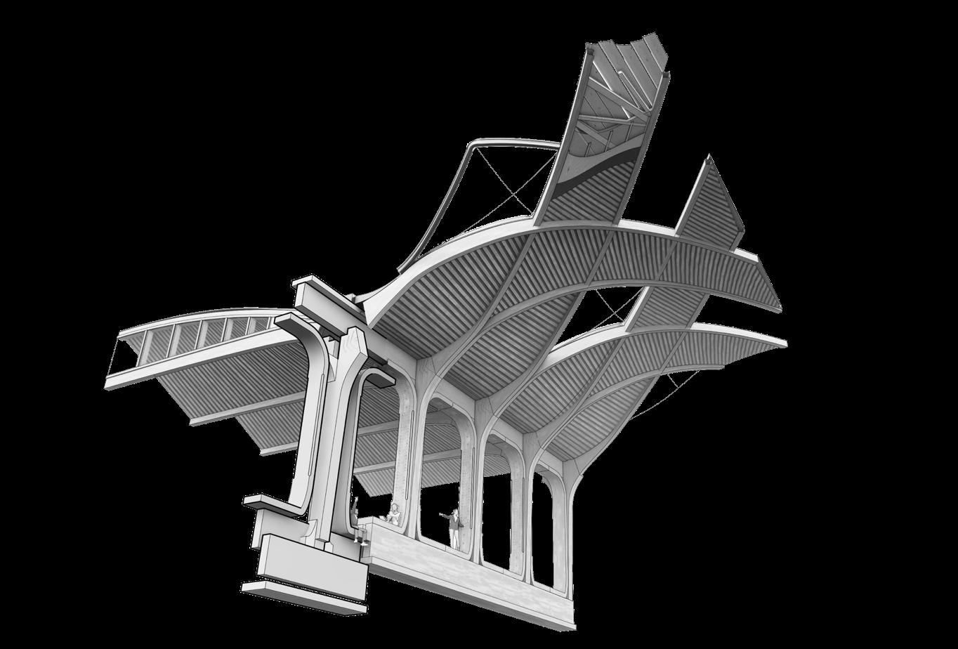
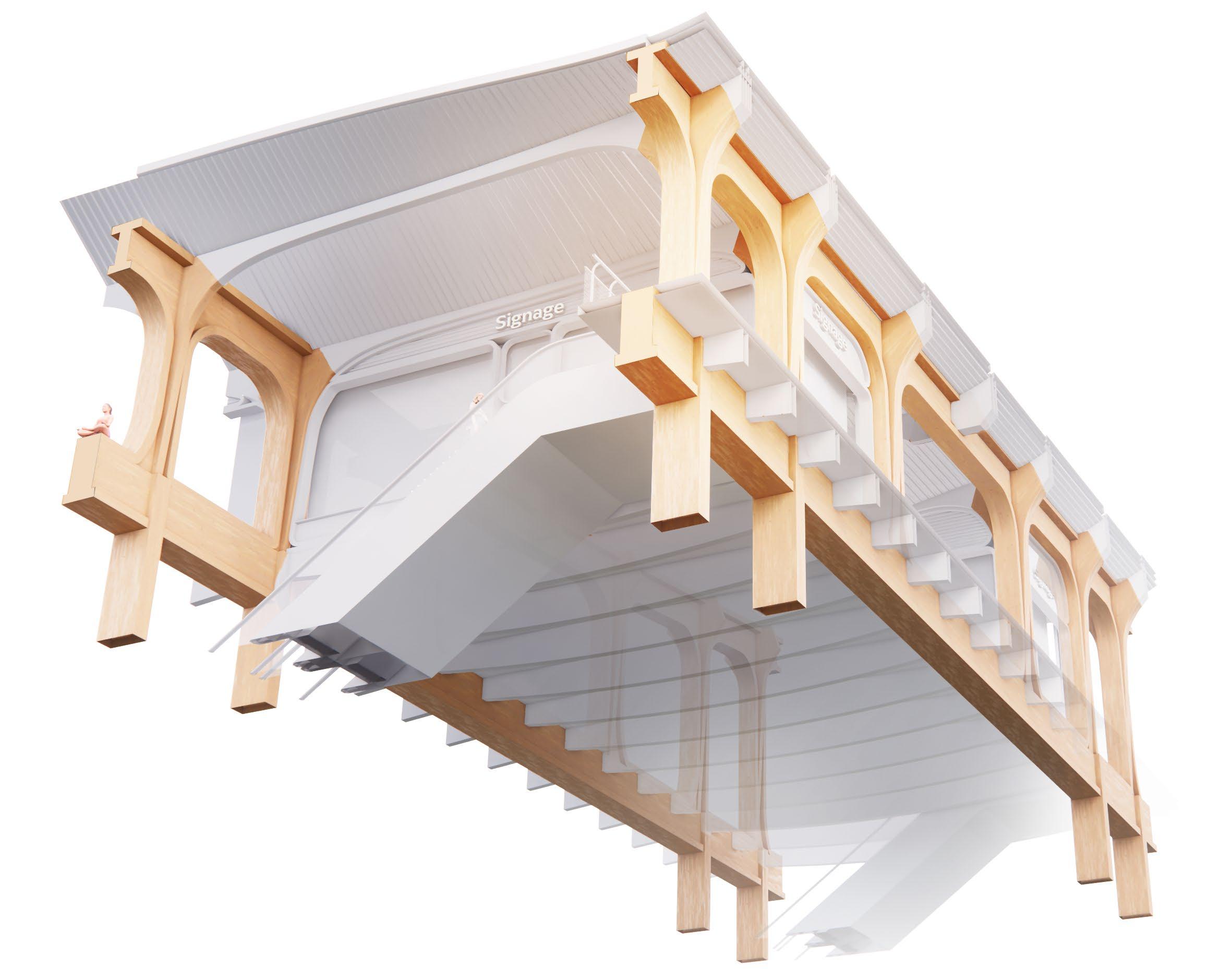
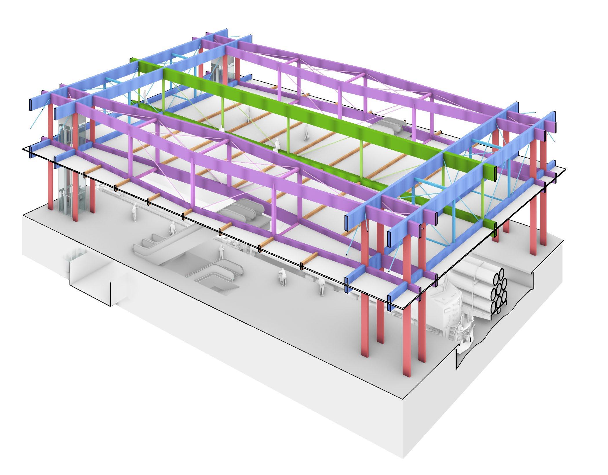
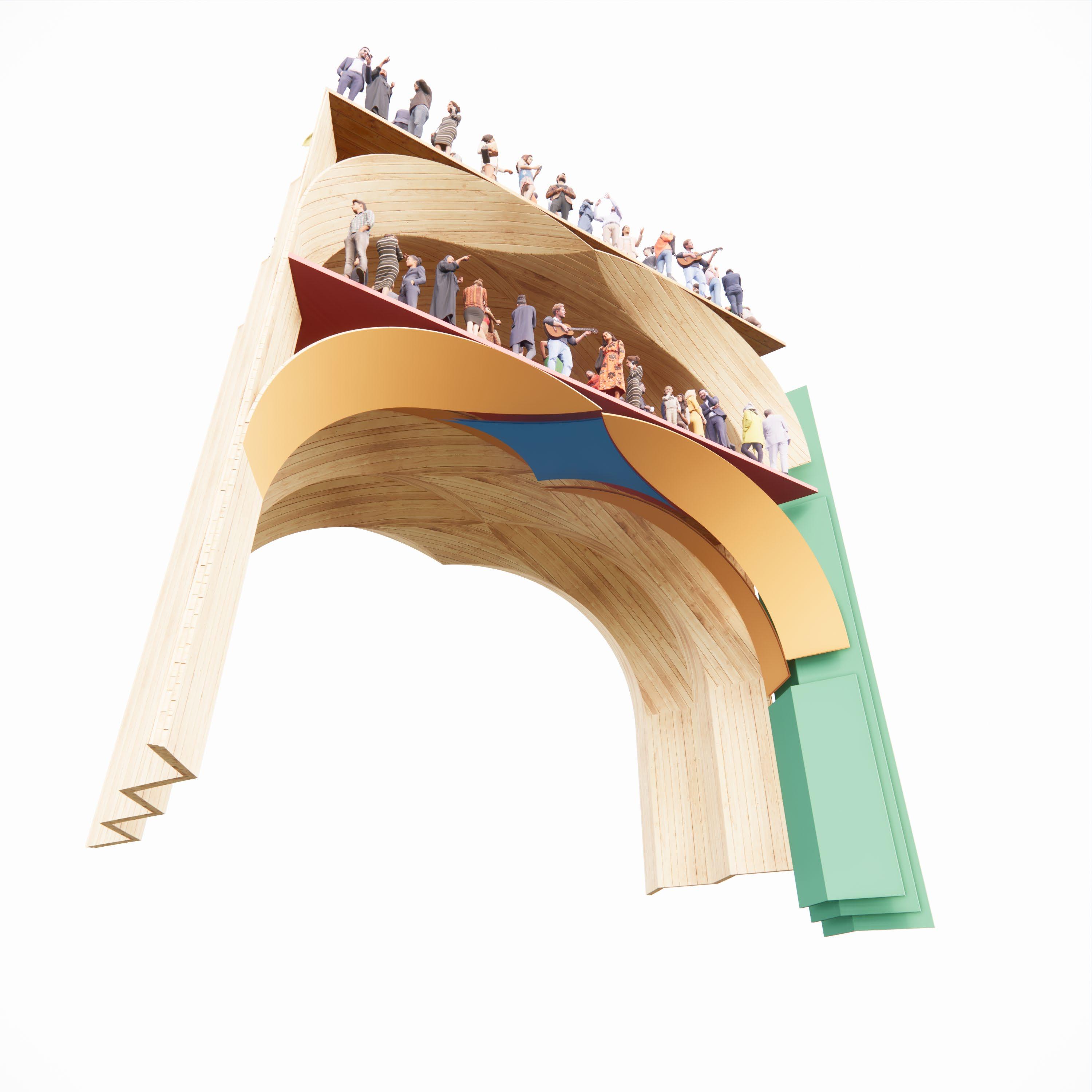
Vierendeel Trusses
Primary Structure
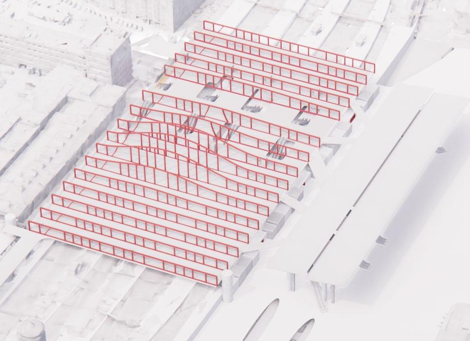
LINKING EXISTING PATHWAYS
15
16 - P ROPOSAL
17
20 - P ROPOSAL
21
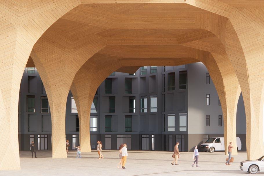
2.2. APPROACH TO THE STATION
22 - P ROPOSAL
1970s canopies
23
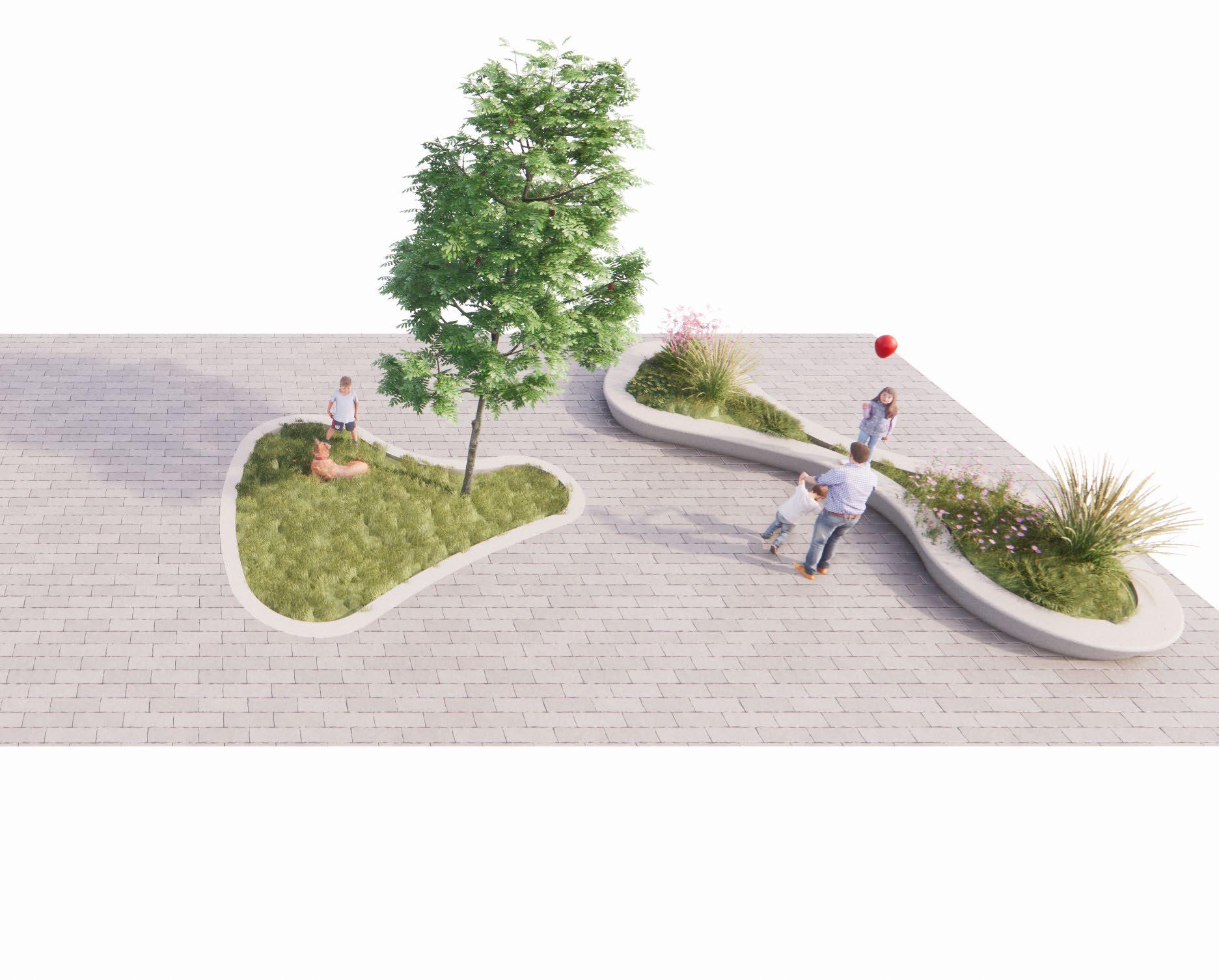
Type A
Seating
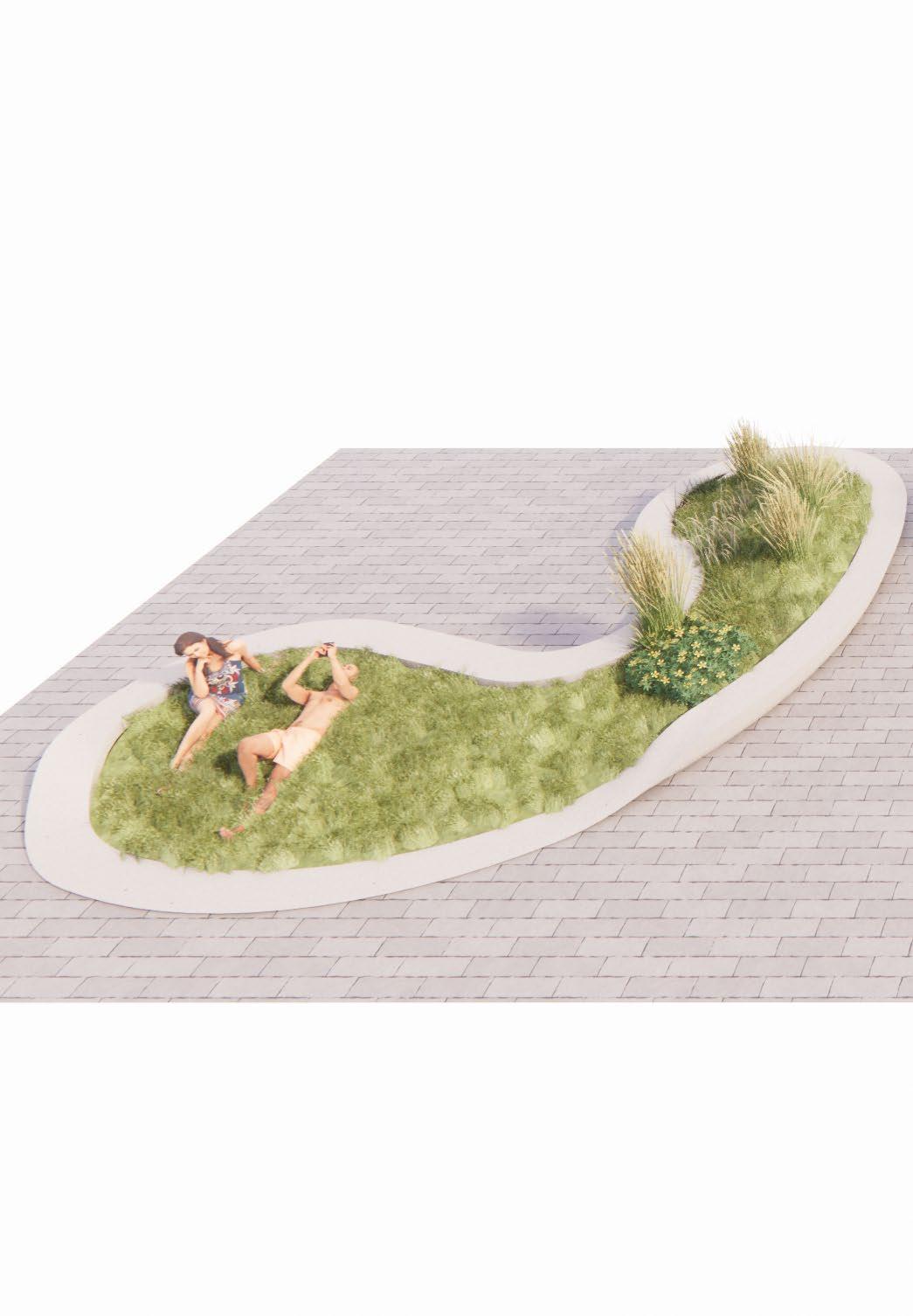
Type C
Laying
Type B
Storm Water Absorber
24 - P ROPOSAL
25
26 - P ROPOSAL
27
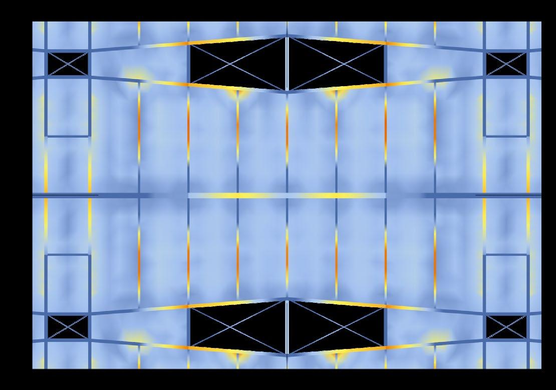
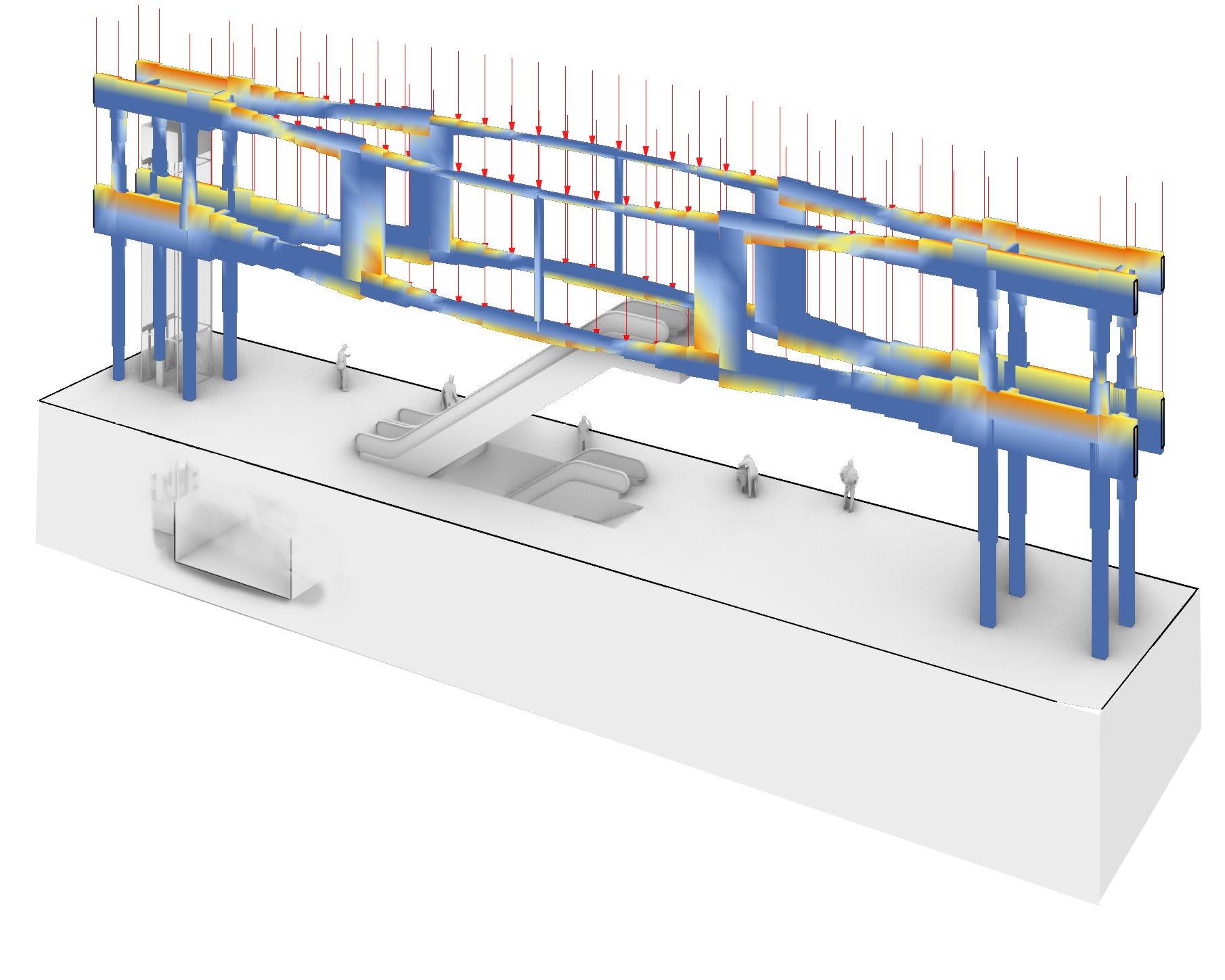
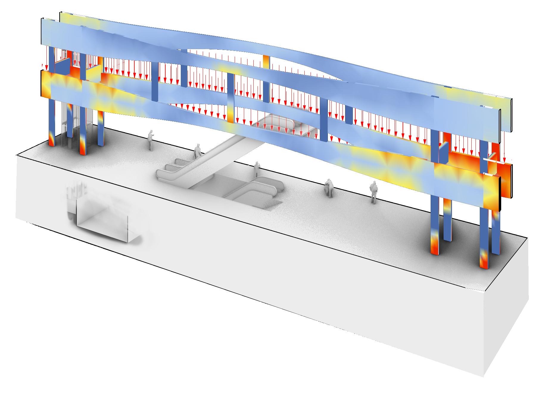
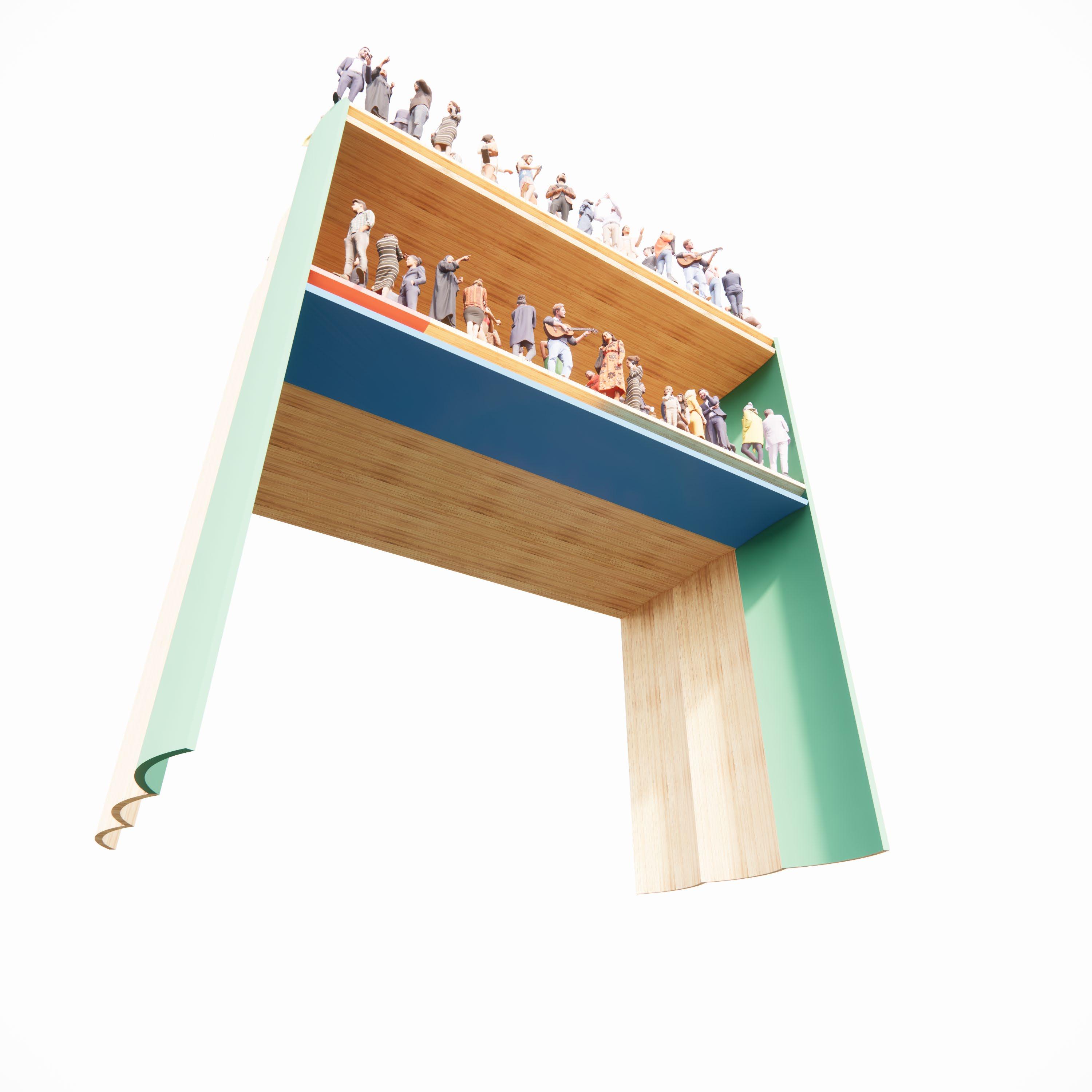
VIEREN d EEL TR u SS
Inhabiting Virendell truss

28 - P ROPOSAL
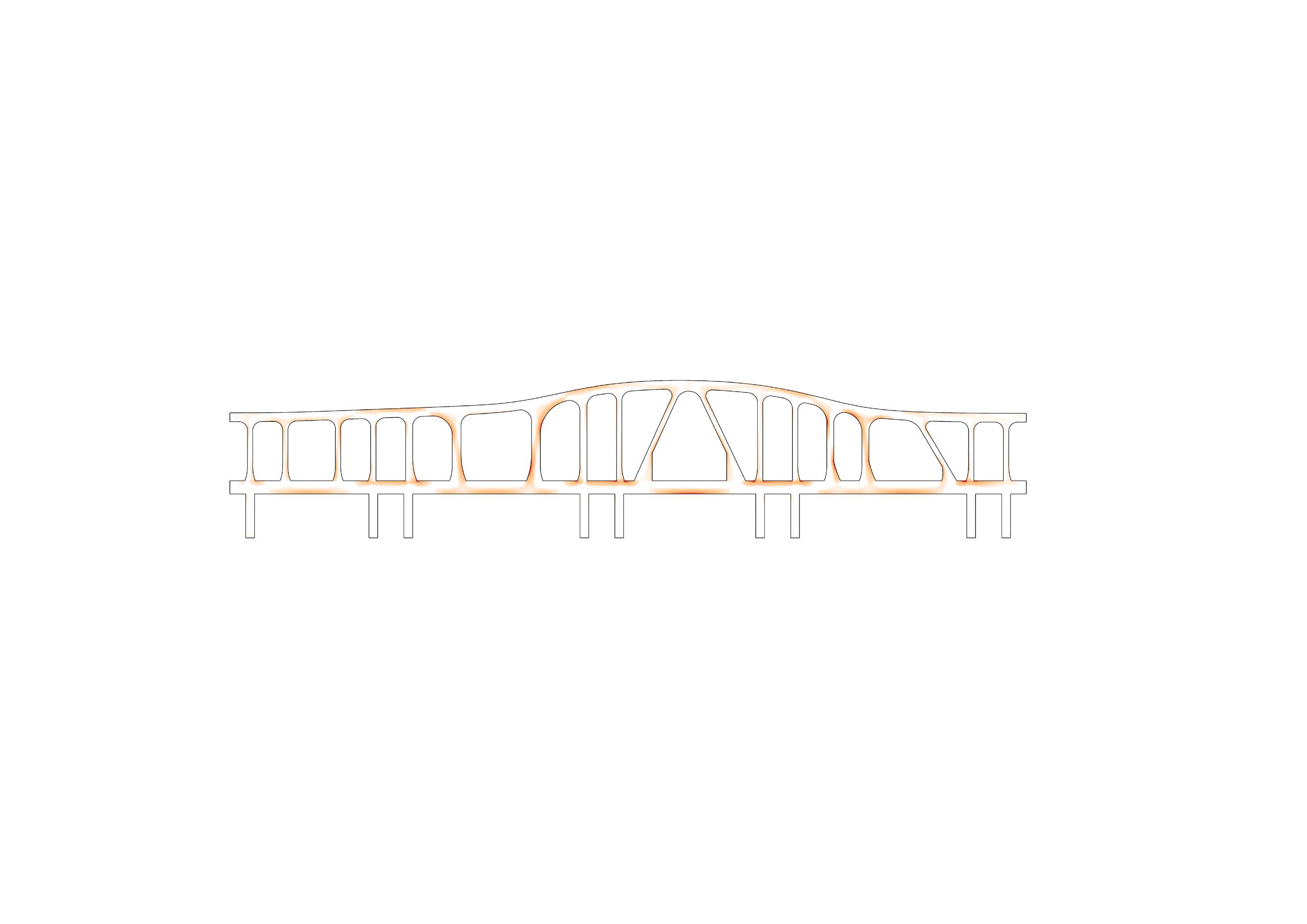
2.3.
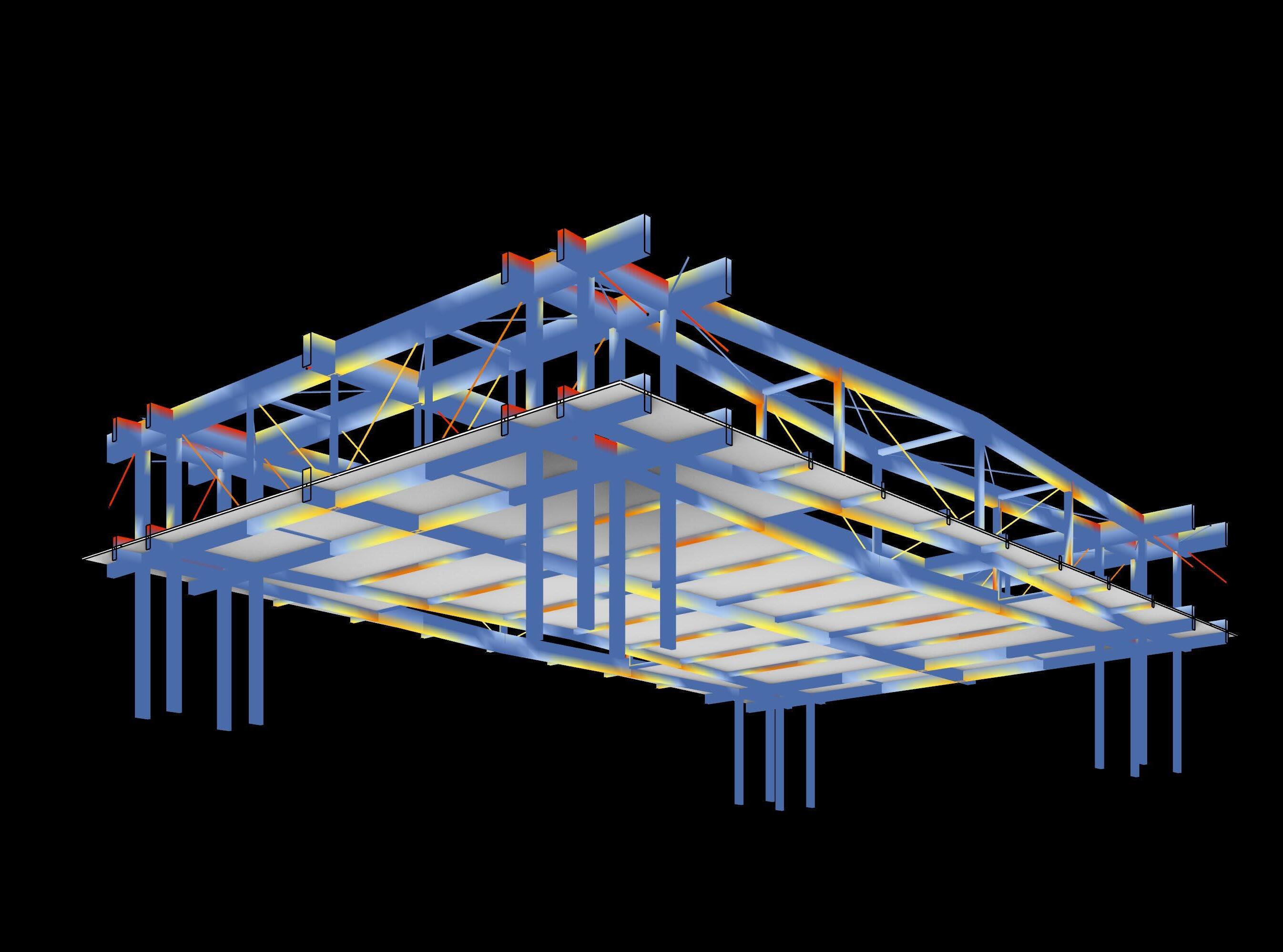
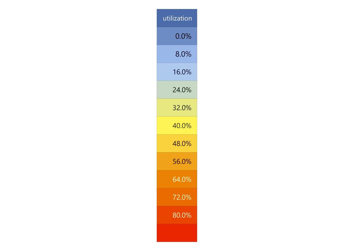
Many areas beyond 80% utilization
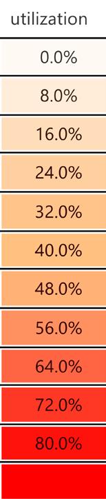
Modelled as solid shell of constant thickness of 300 mm All joints and supports fixed and constrained in all axis.
Loads:
Total of 8600 kN acting on bottom of the truss and total of 2000 kN on the top
29 4.0 20.0 4.0 16.0 4.0 20.0 4.0 14.0 4.0 20.0 4.0 16.0 4.0 20.0 4.0 14.0
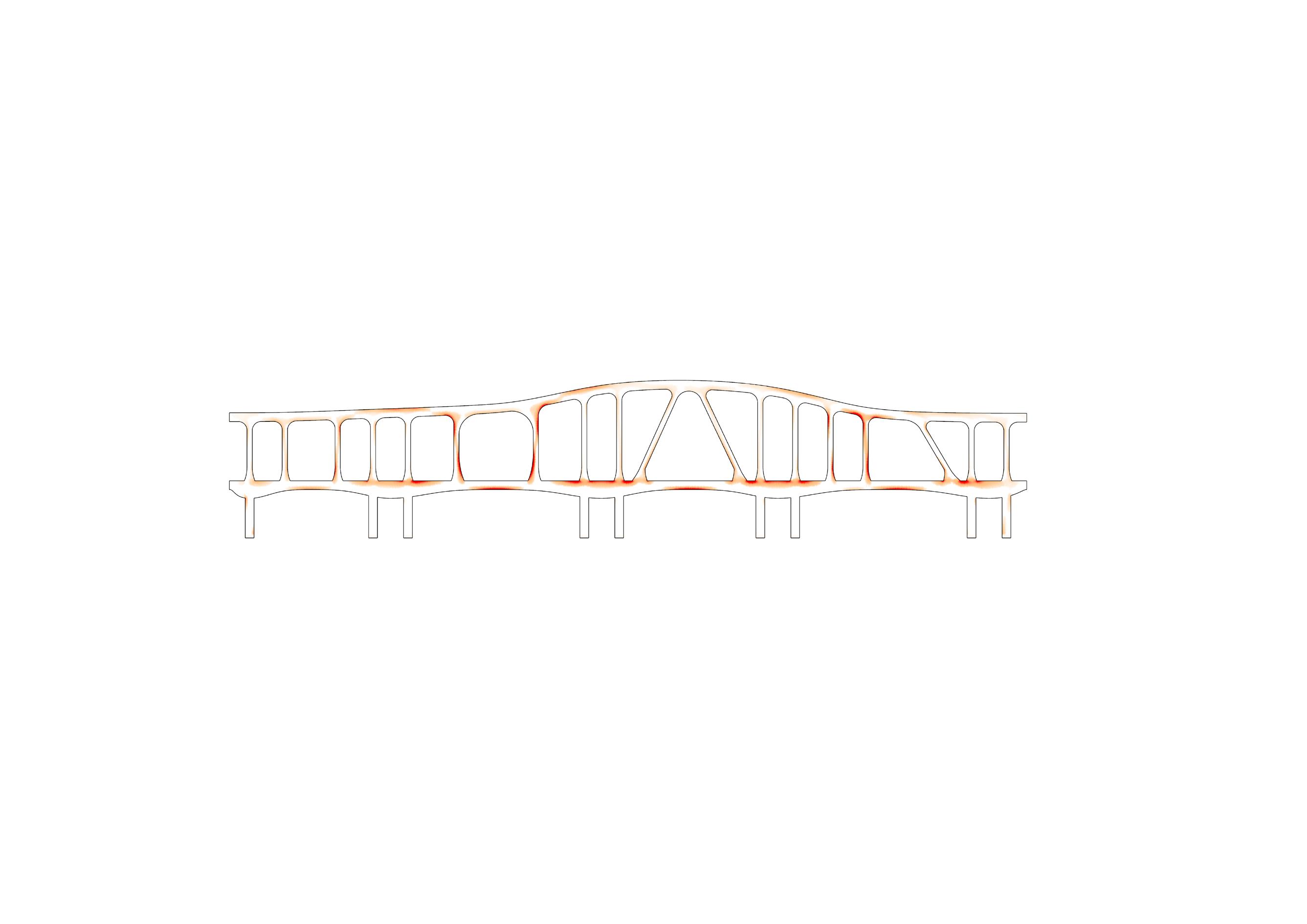
Early Iteration
Late Iteration Pruning redundant hunches Eliminating bulges of the bottom chord Adjusting hunches Increasing width of some posts
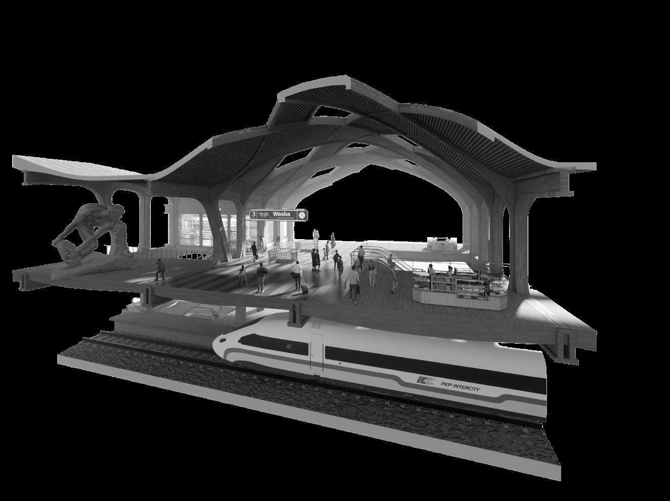
2.4. FRAGMENTS OF PROGRAM
32 - P ROPOSAL
Museum
33
Food
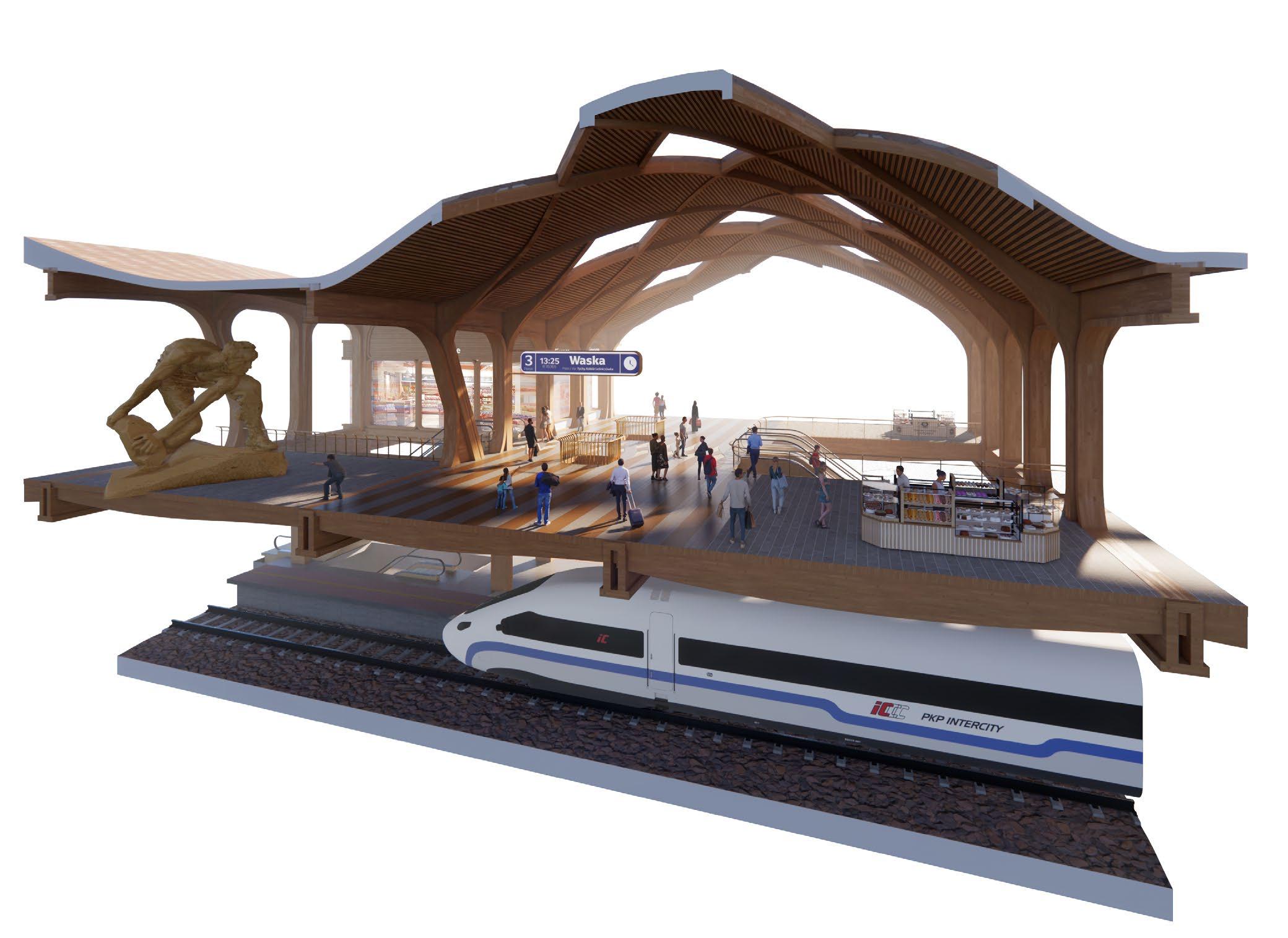
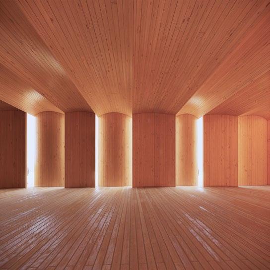
Main Concourse
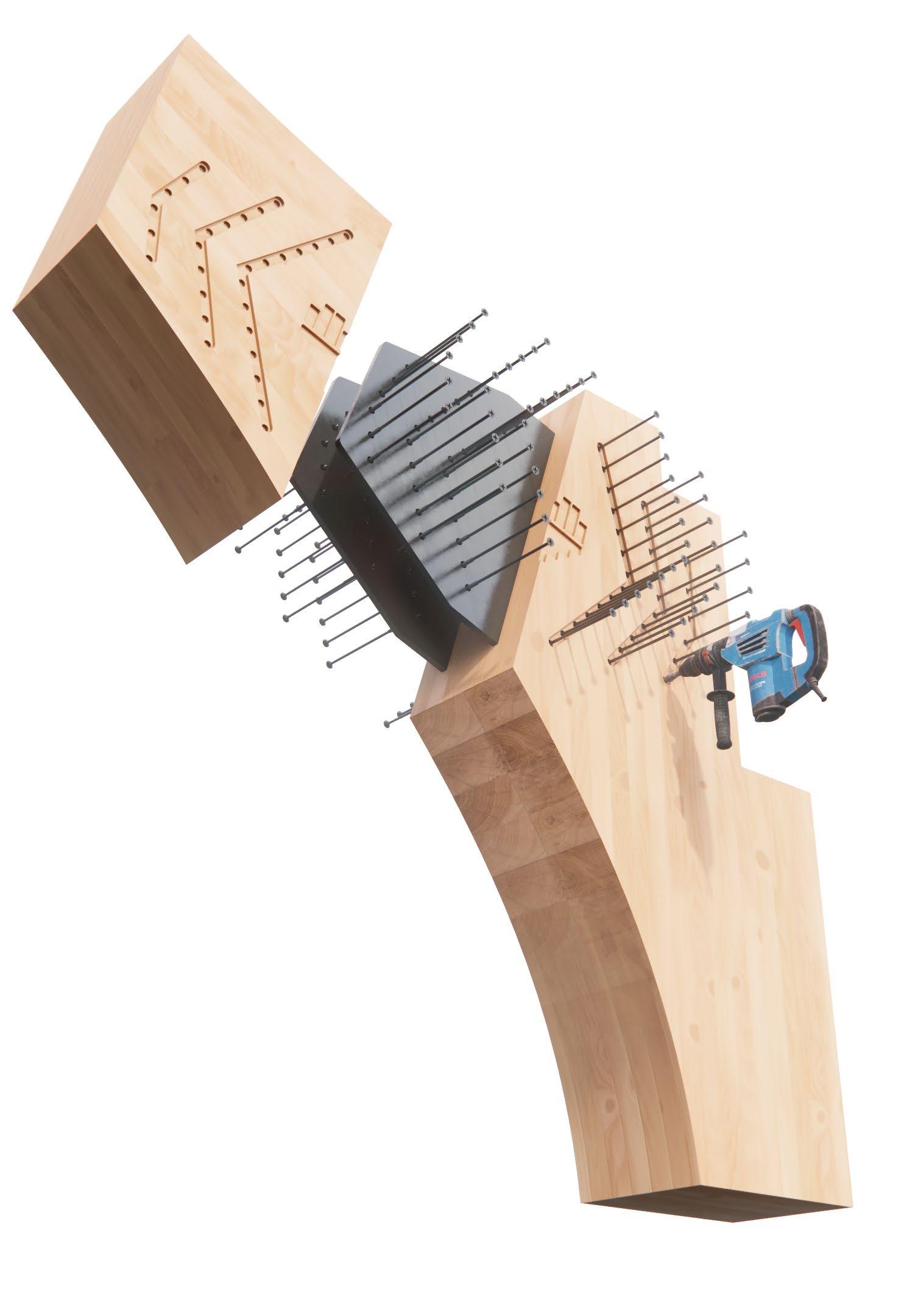
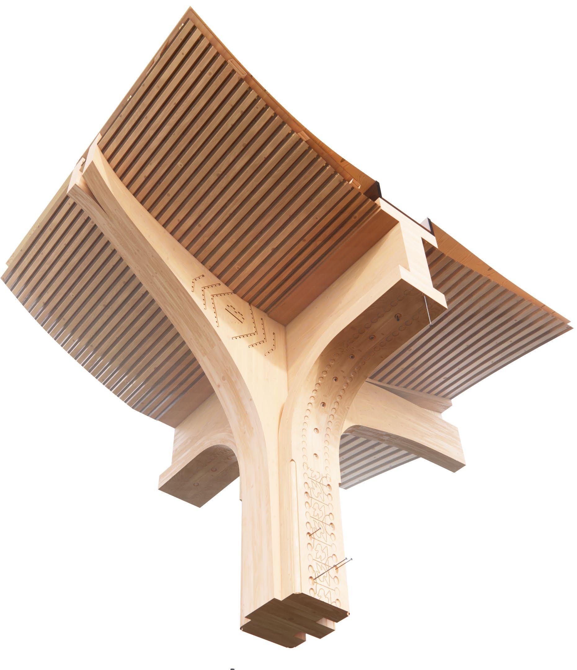
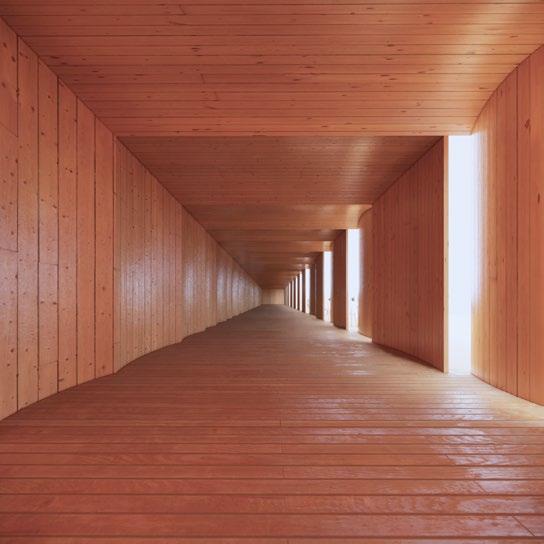
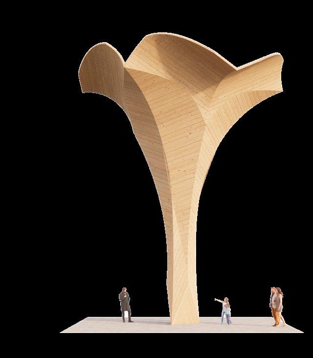
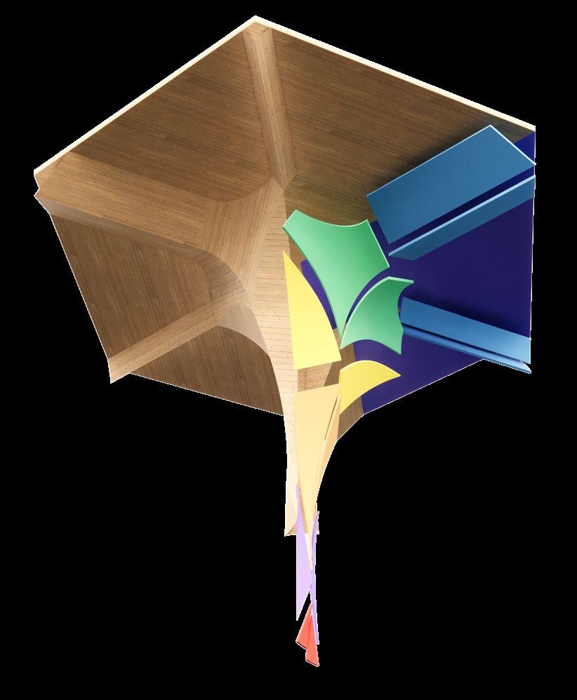
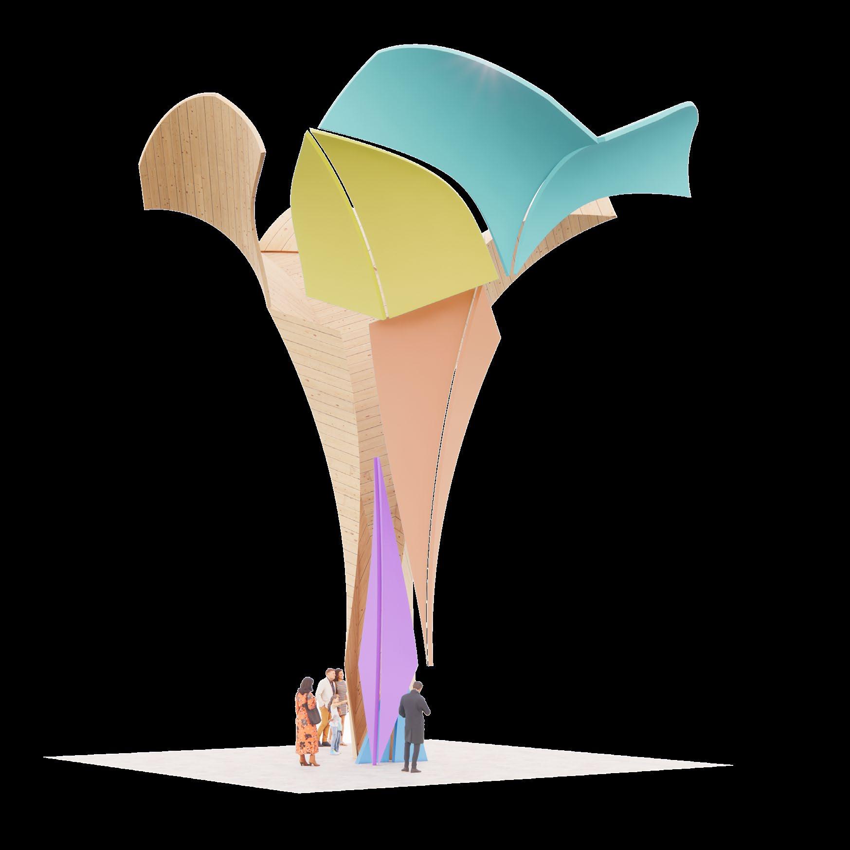
2.5. TECTONICS OF OF THE ROOF AN d THE TR u SS
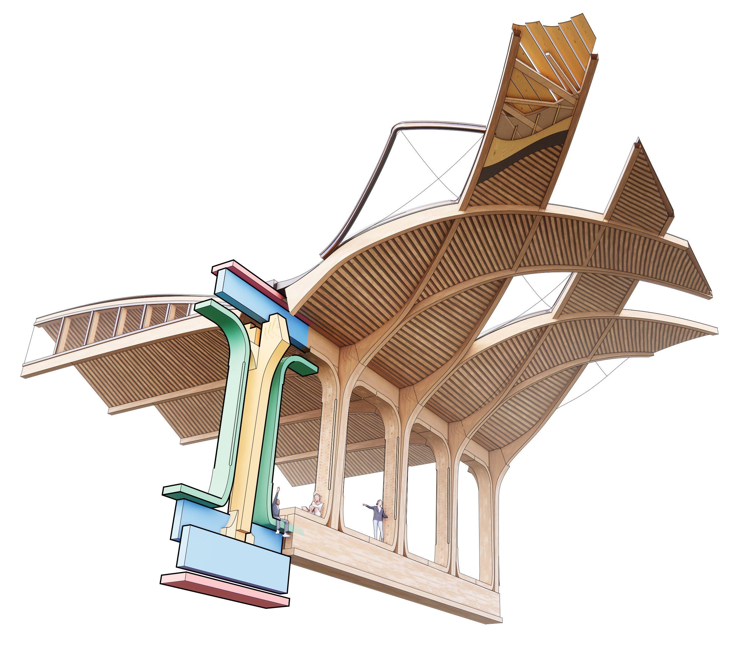
34 - P ROPOSAL
35
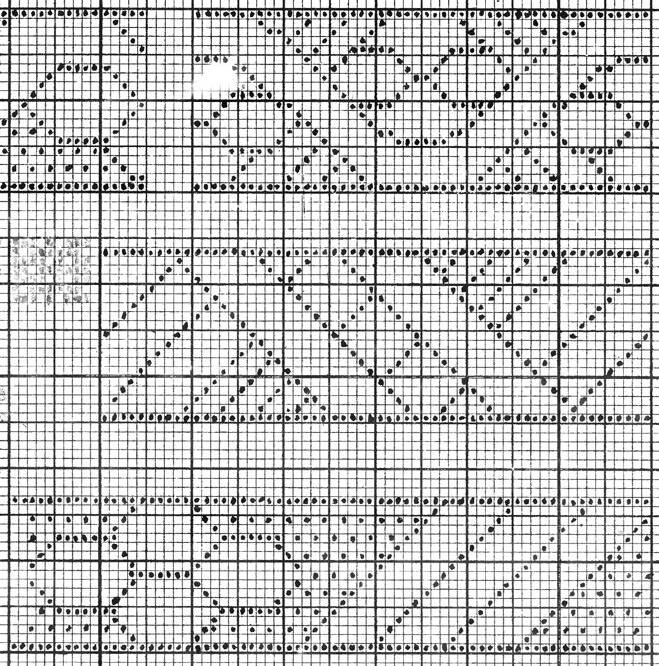
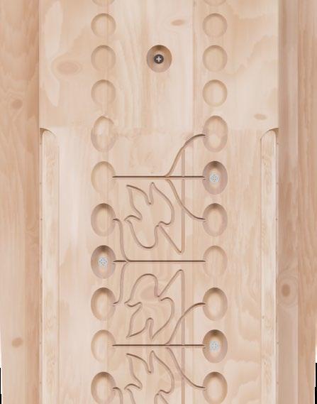
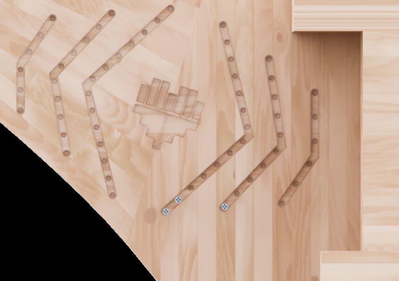
2.6. C u LT u RAL CONTEXT
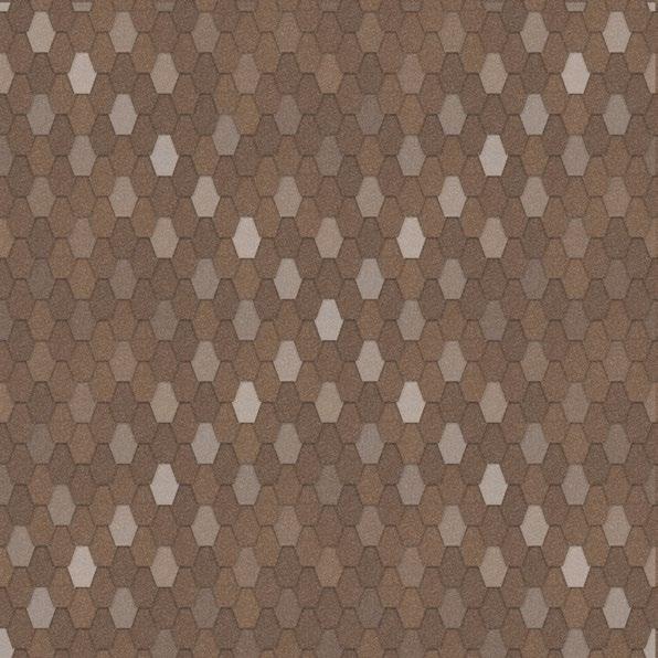
SILESIAN AND POLISH EMBROIDERY
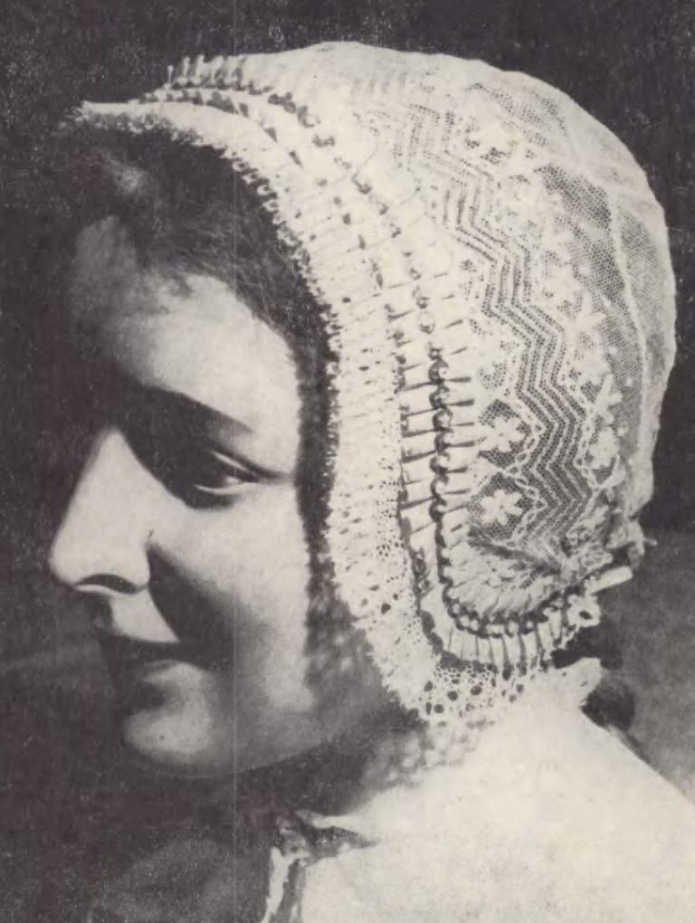
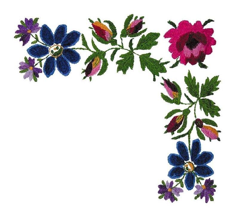
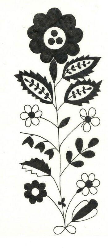
(Monochome top) ‘Haft na żywotku cieszyńskim’, p. 32, 45. Czeski Cieszyn, 1985. (left) ‘czepiec czółkowy’, Nierodzim , Muzuem Slaskie, 1918-39 (bottom) ‘Wzory do wyszywania cechu pasamoników w Cieszynie’, p. 54, Książnica Cieszyńska, 1866-1910
36 - P ROPOSAL
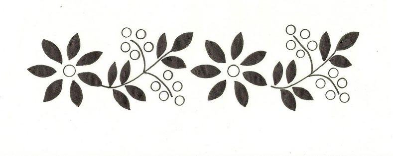
INTERPRETATION OF THE EMBROIDERY MOTIFS ON THE ROOF OF THE STATION
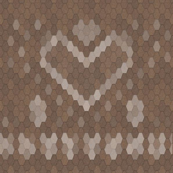
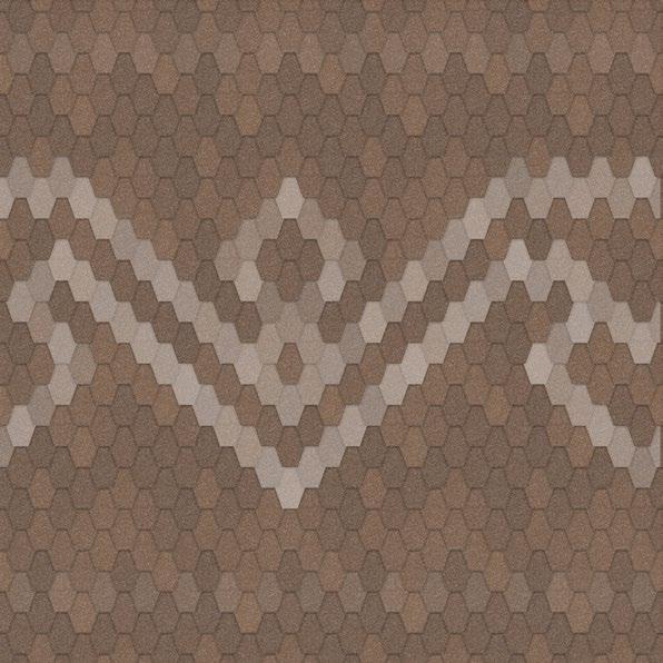
37
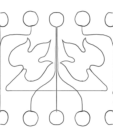
UPPERSILESIAN AND PODHALE ORNAMENT IN TIMBER
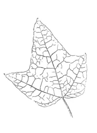
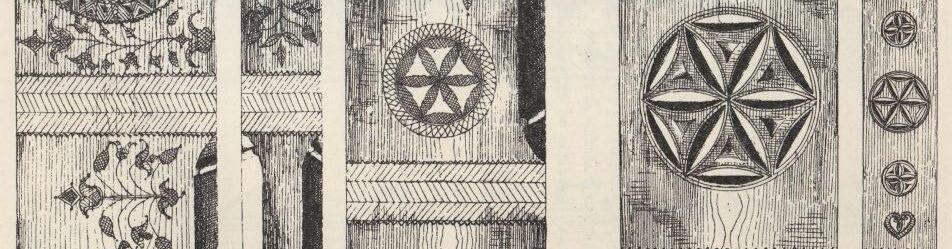
SILESIAN FOREST OF MAPLE
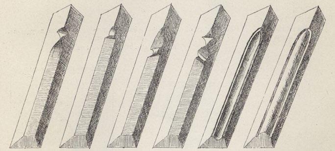
Interpretation of Traditional motif with
Chamfers of Structural members
Examples of traditional motifs chiselled in wood
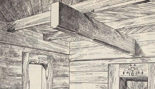
38 - P ROPOSAL
Maple leaves
Leaves of Maple ‘Stollii’, Fritz Graf von Schwerin, Gartenflora, 1893
Copying of the ornament of Carpenters’ Manuals of 18th c. is historicism. This project aims to create contemporary ornament.
‘Zdobienie i sprzęt na Podhalu’ Warszawa : skł. gł. E. Wende, 1901
CONTEMPORARY MOTIFS WITHIN THE BOUNDS OF THE TRADITION
39
Chapter 3 - appe NDIX
175 20 20 100 120 20 20 30 20 30 30 20 60 30 30 175 100 20 20 30 20 30 30 20 60 30 42 - A PPEN d IX GL36c All beams are glulam Rope PV All bracing is steel cable by www.pfeifer. info T28 E14,5 T28 E14,5 T20 E12,5 T20 E12,5 T15 E11,0
SELECTED DRAWINGS FROM AUTUMN-WINTER SEMESTERS
20 60 22 20 20 120 20 10 20 20 30 50 20 60 22 20 20 120 20 10 20 20 20 20 120 30 30 50 43
SIMPLE RATIONAL TR u SS STR u CT u RE
Loads: 6 kN/m2 on all CLT slabs + Gravity 3.1.
Load
21 4 3 32 3 4 4 24 4 24 24 3 21 4 3 4 24 24 4 3 4 3 21
One top beam takes 450 KN, one bottom beam takes 900 kN

Load
24 4 4 32 24 4 24 4 4 4 44 21 4 3 32 3 3 4 24 17 3 4 21 4 4 24 4 24 24
Total of 1200 kN distrubited evenly on each bottom beam (two beams) + half of that on top
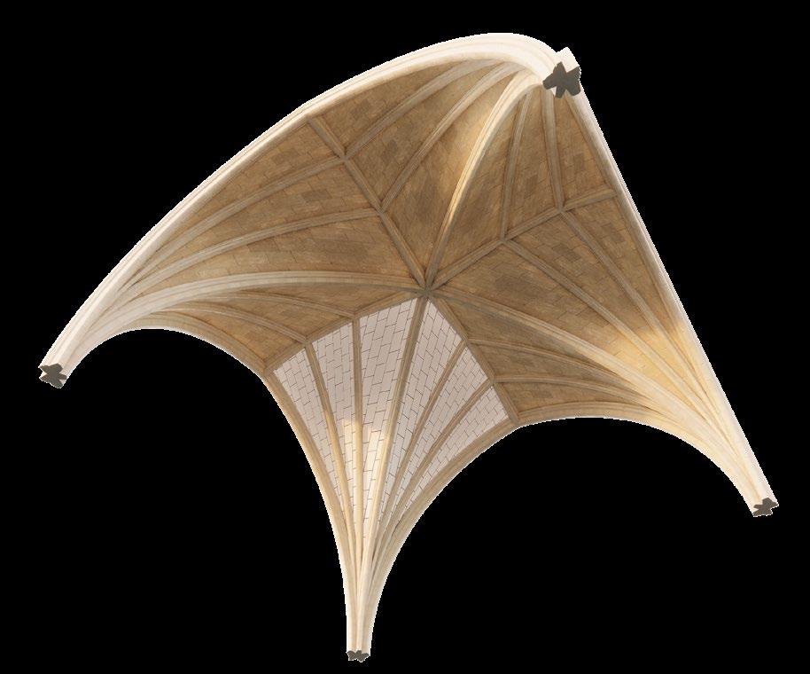
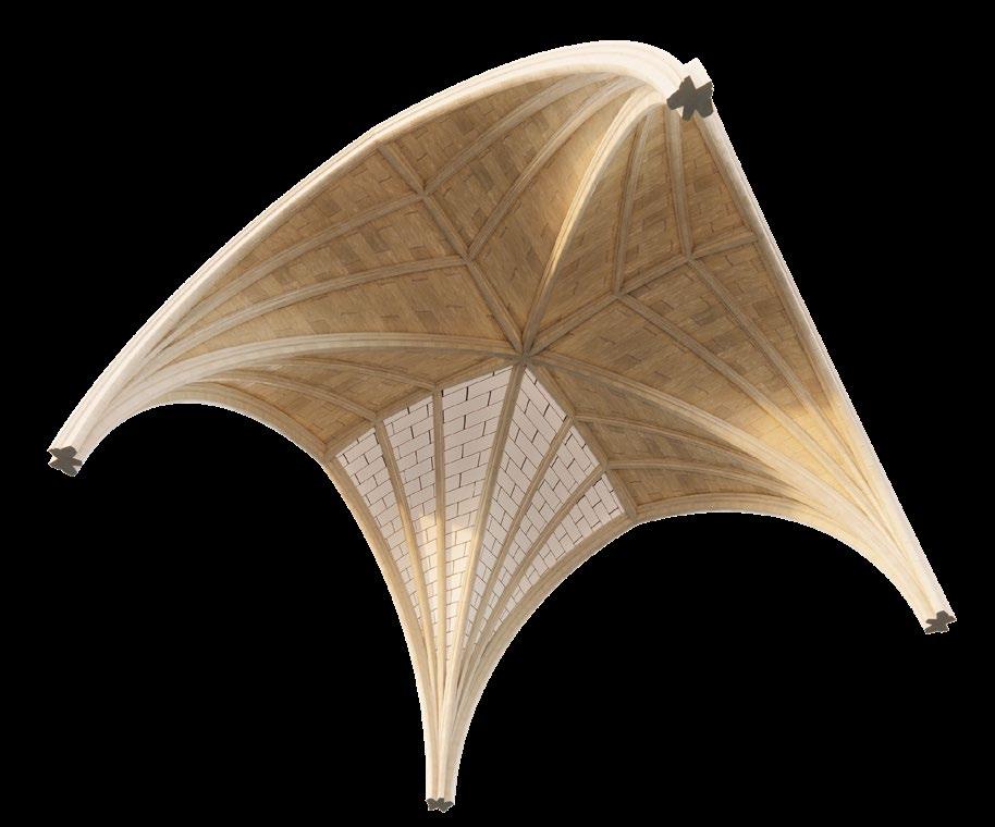
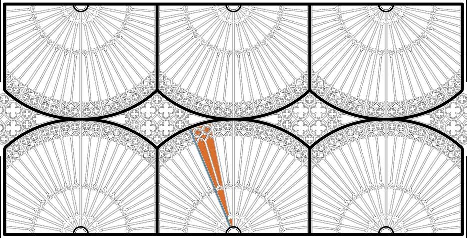
3.2. RIBBE d TIERCERON VA u LT
LA CHAPELLE DE L’HÔTEL DE CLUNY, PARIS
Stone coursing pattern
The stone coursing pattern of cross vaults was different in England from what was used in France and the rest of Europe. In England the joints formed right angles with the diagonal ribs (while in France the joints were parallel with and perpendicular to the longitudinal direction of the cross vault).
46 - A PPEN d IX
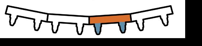
Frame + Shell structure


There are two main construction techniques to formulate the shell surface of a fan vault: the jointed masonry system and the rib-and-panel system (often used together in the same structure, alternating along the height)

Constant Curvature Arc


On the Right another type of Arch - Tudor
Hierarchy of ribs
They vary in depth, width as well as the level of their placement


Single curvature
The masonry infill between ribs are arrayed around the centre but are single curvature.


47
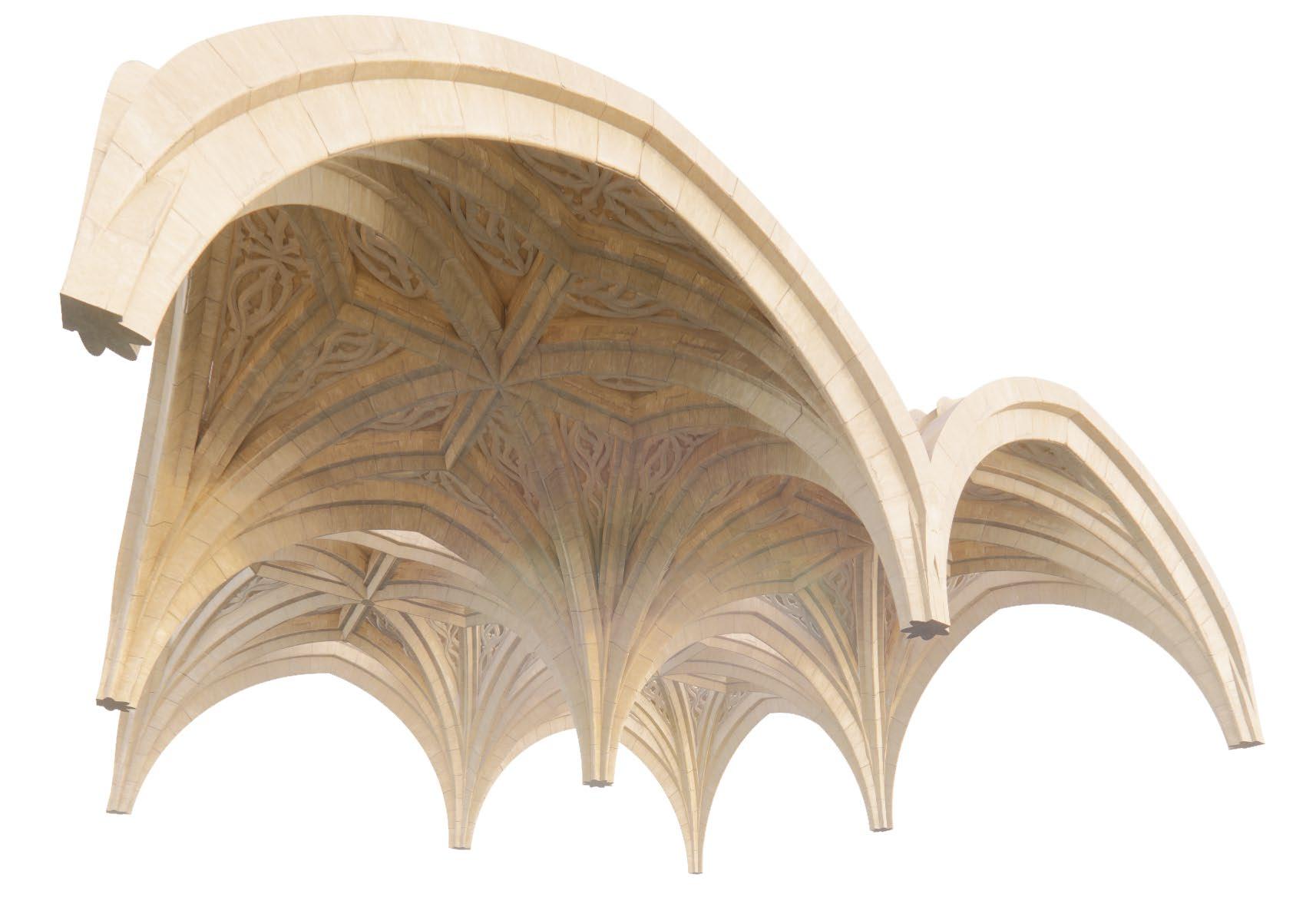
Partly intersecting conoids


Bath Abbey
3.3. FAN VA u LT BATH ABBEY
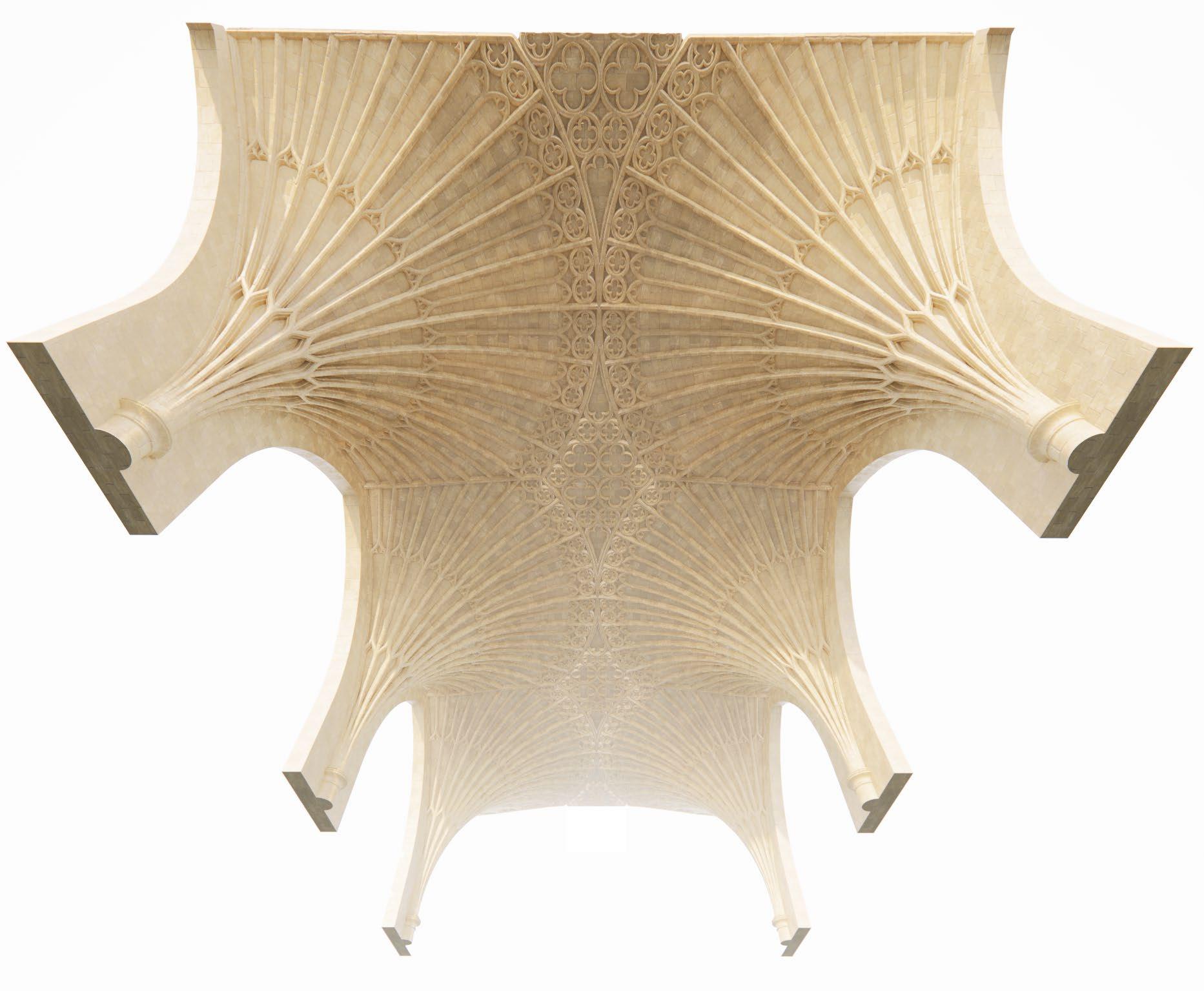
Another types
Other English Structures
48 - A PPEN d IX
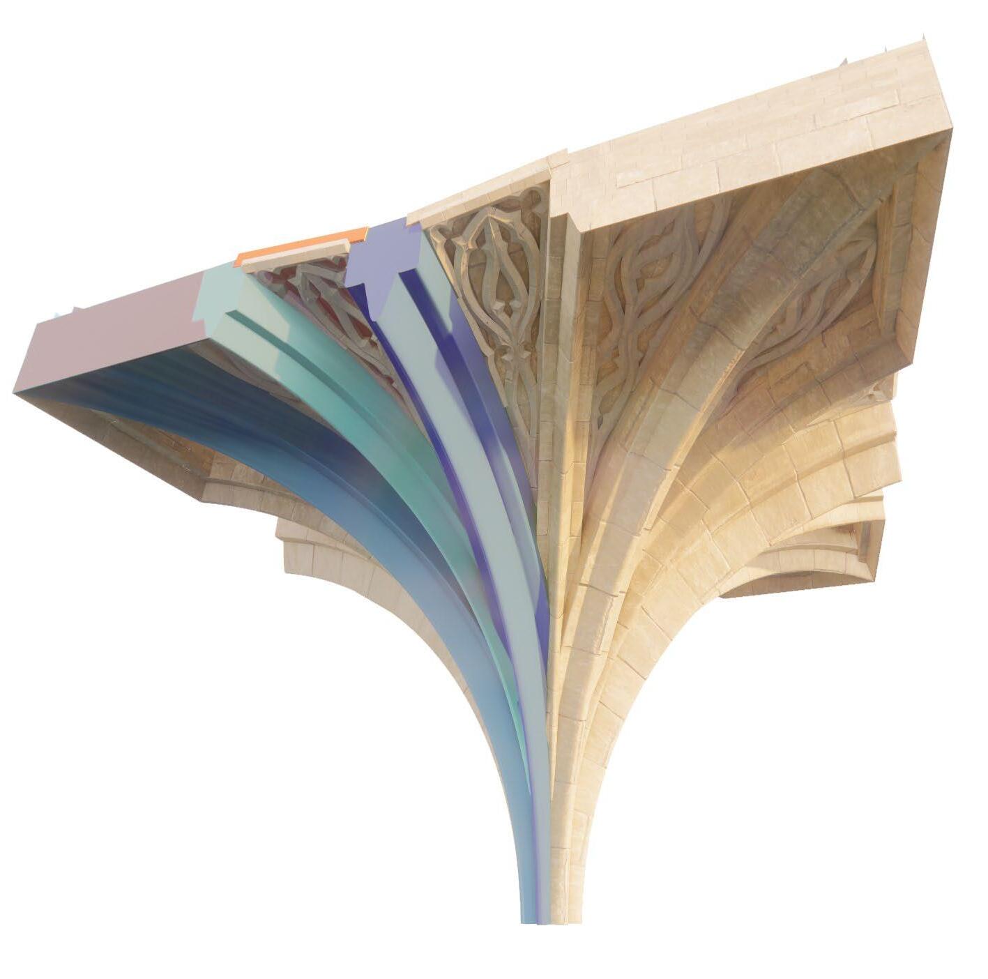
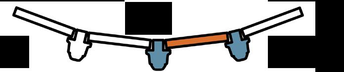
“Tas-de-charge”
At equal angles congruent vertical ribs rise up from the a piece of stone block carved to give the appearance of separate ribs joining together.
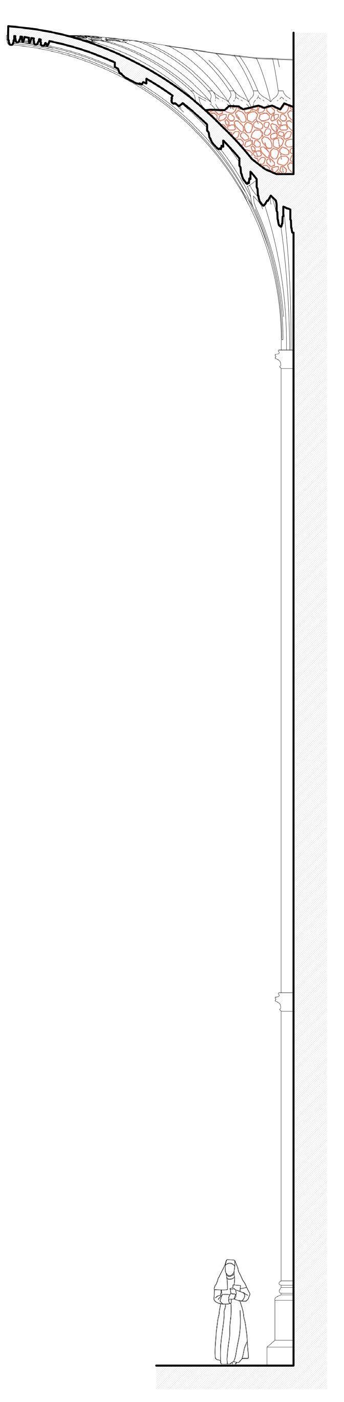
The Vaulting Pocket (section right)
Shell structure
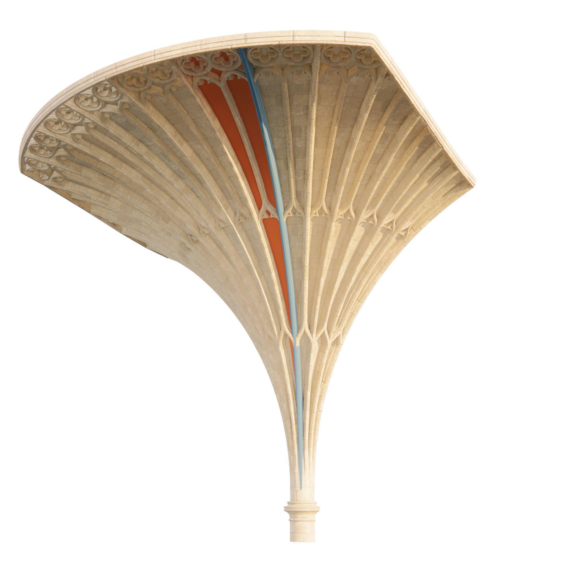
Jointed masonry system the flat masonry blocks are laid on a centring to formulate a shell surface, and the “ribs” are sculptured on their surface, to give a nice appearance while in fact the structure works as a shell.
The vaulting pocket is often filled with rubble. Thrust line goes outside of the shell if the pocket lacks the infill. Because of the infill the forces are distributed over much larger area. It also stabilizes against buckling. The infill reduces the span of the shell so the region working as a pure shell is smaller.
49
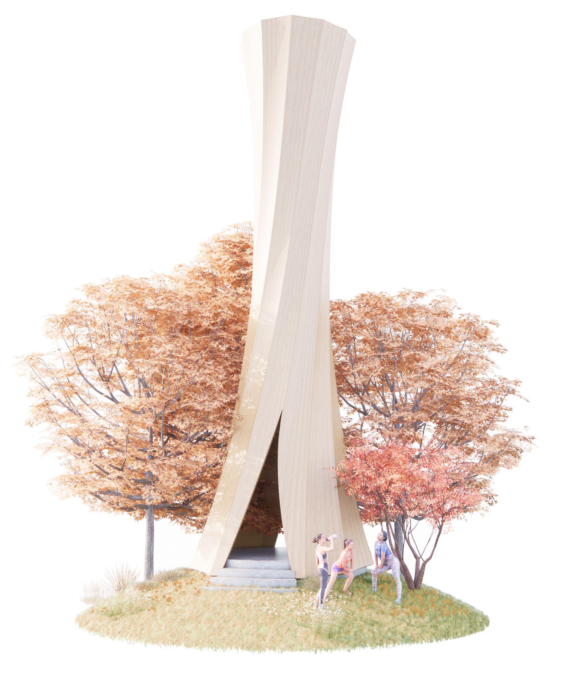
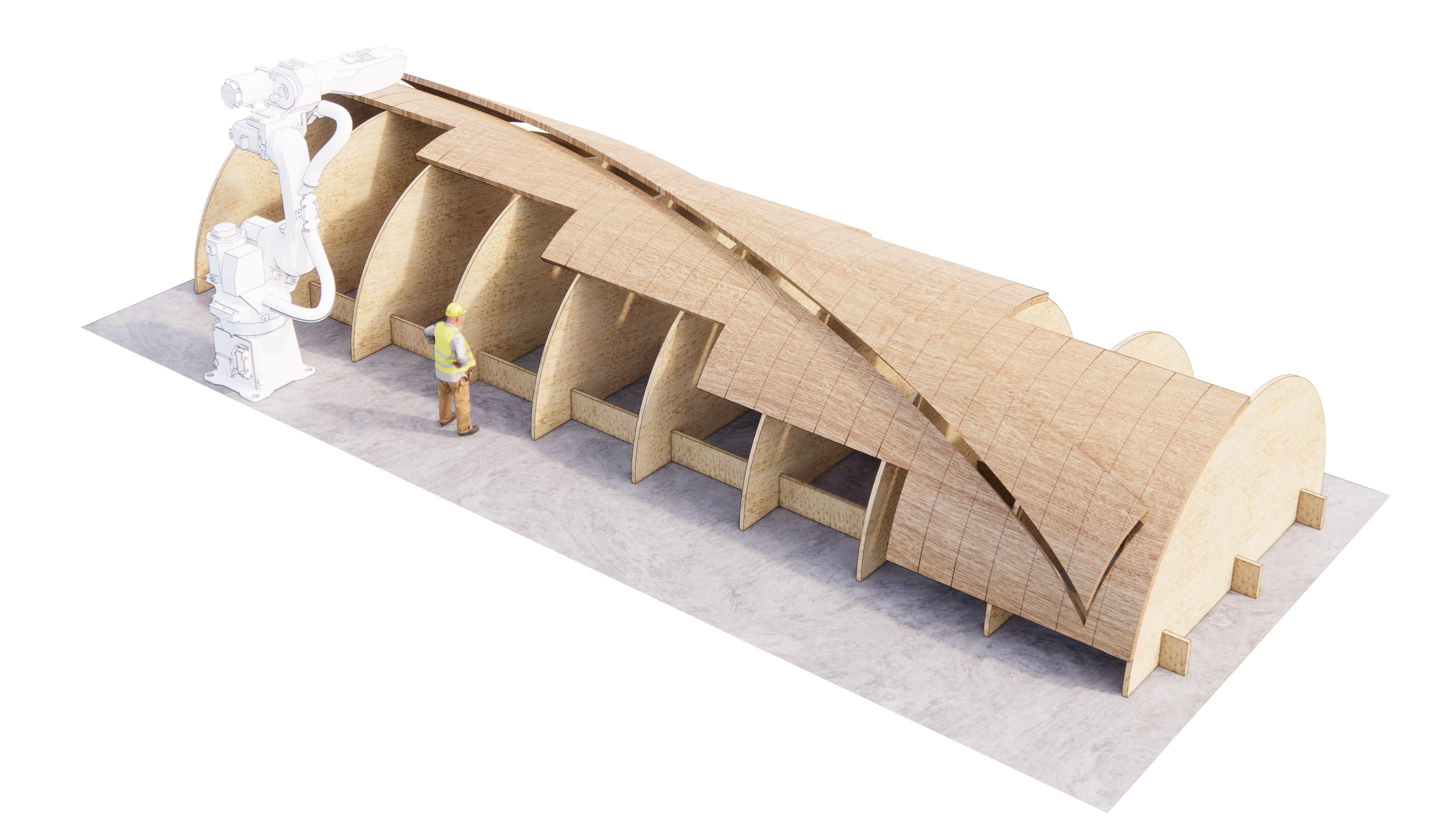
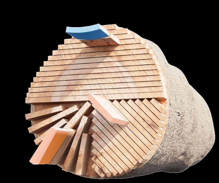
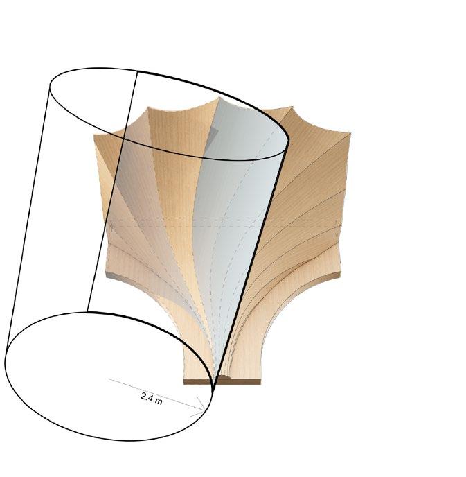
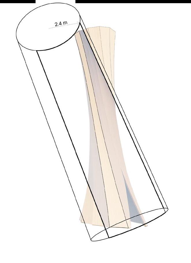
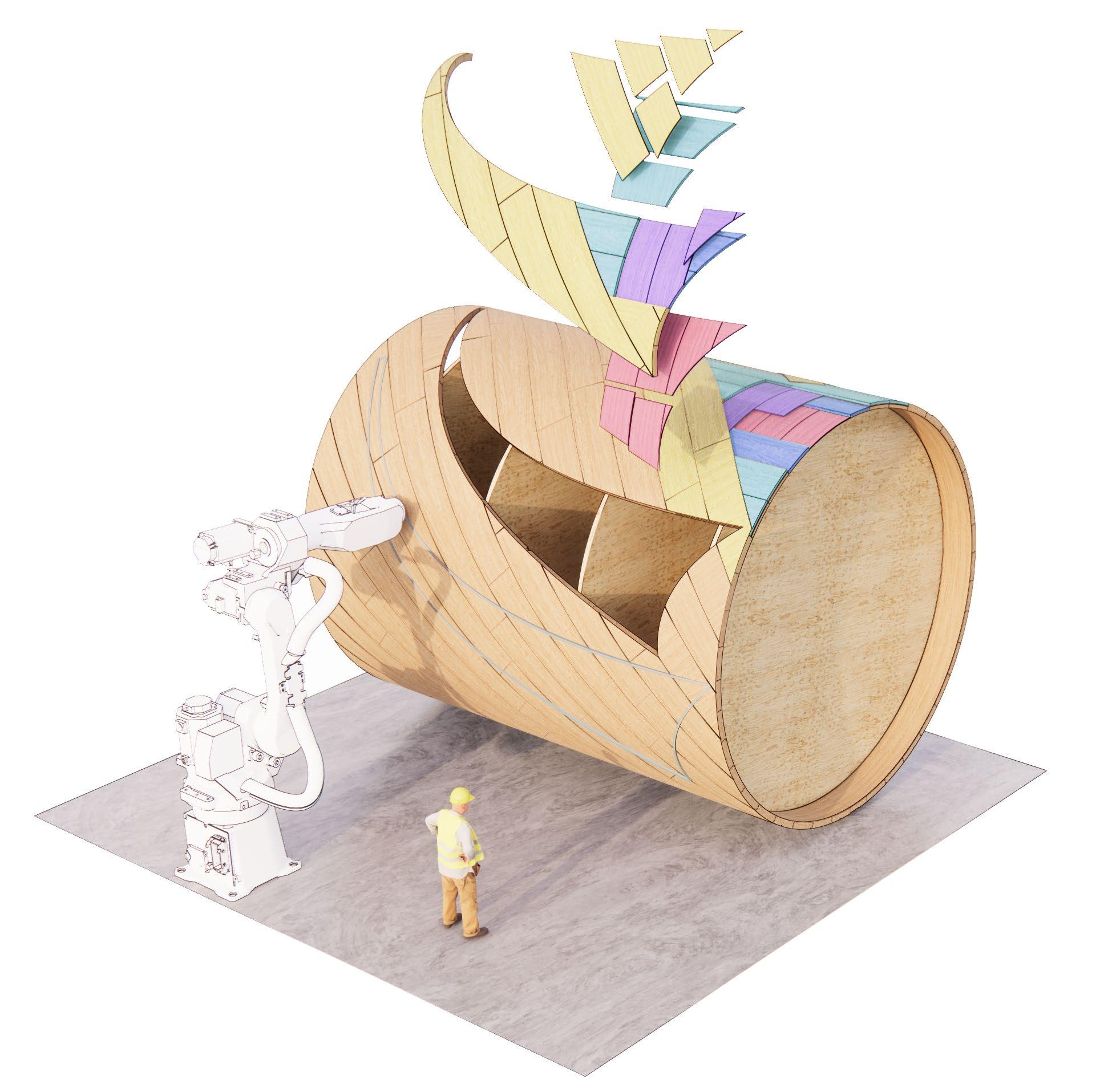
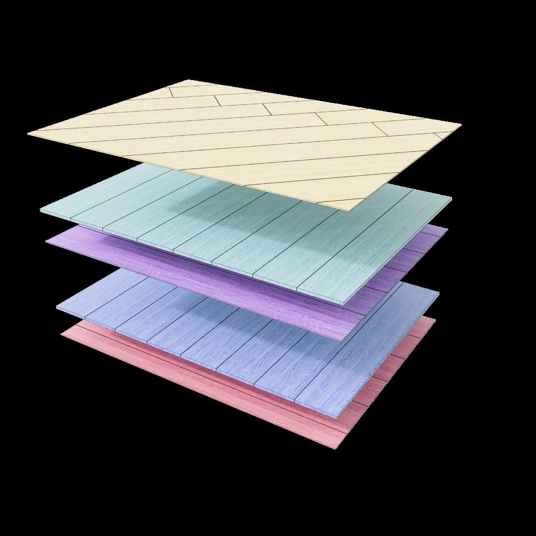
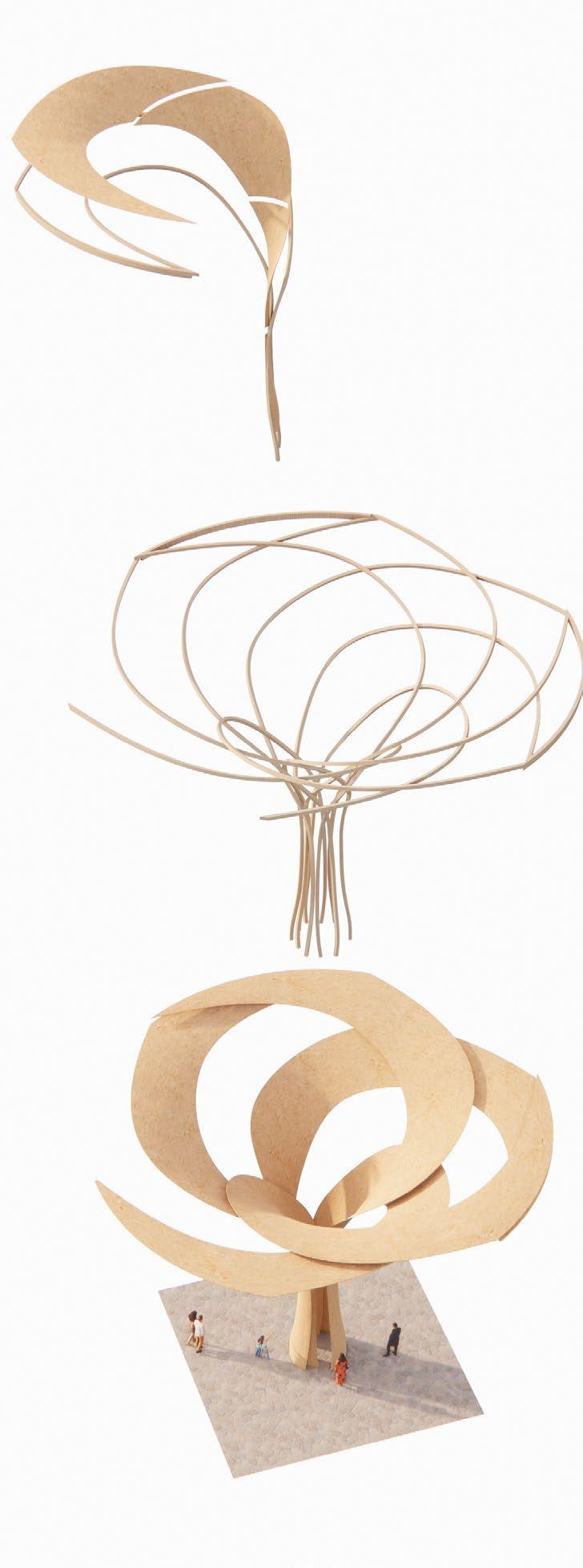
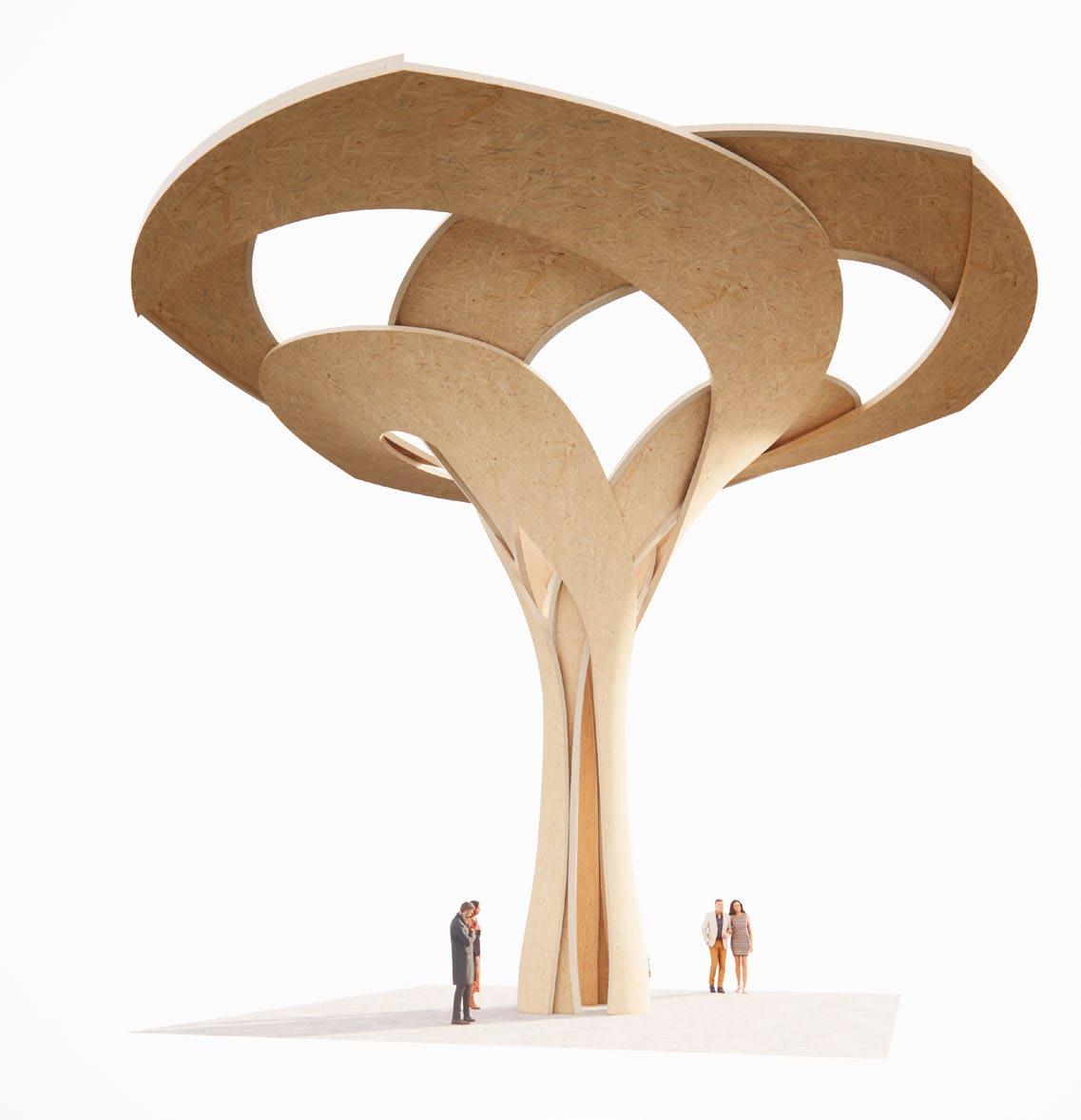
3.4. SELF SHAPE d CLT
‘URBACH TOWER: INTEGRATIVE STRUCTURAL DESIGN OF A LIGHTWEIGHT STRUCTURE MADE OF SELF-SHAPED CURVED CROSS-LAMINATED TIMBER’
50 - A PPEN d IX
WMC = 22% WMC = 12% R=2.4m
Spruce, 10 mm
WMC = 12%
Spruce, 30 mm
WMC = 22%
Self Shaping when drying
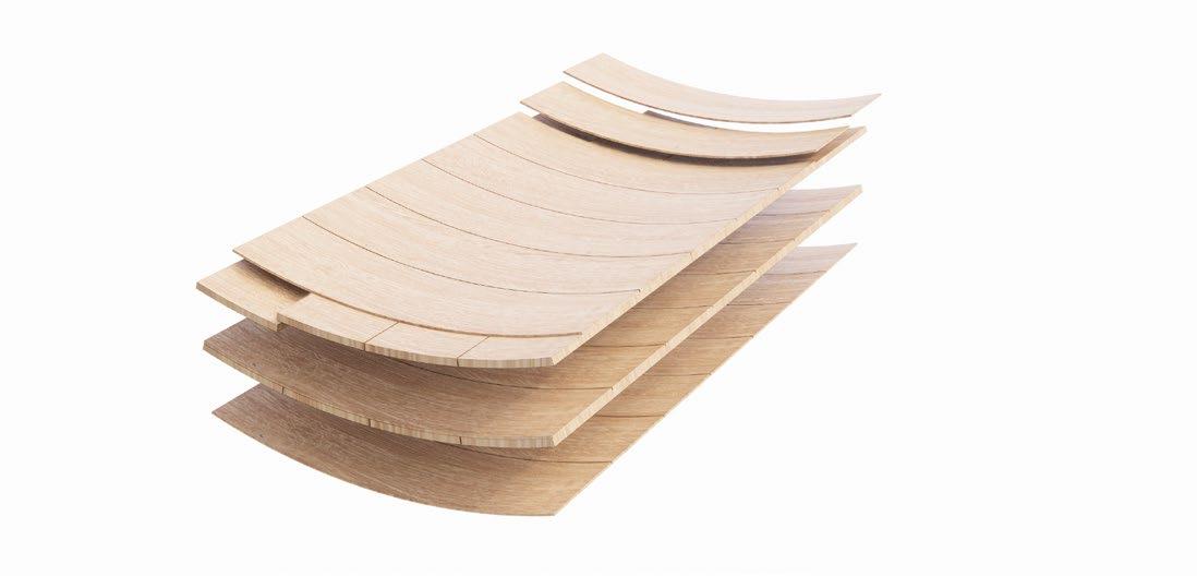
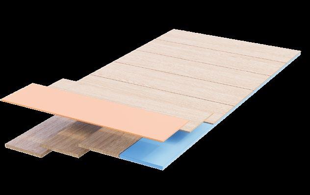
Bi-layer - 40 mm
Bi-layer - 40 mm
Locking Layer - 10mm
51
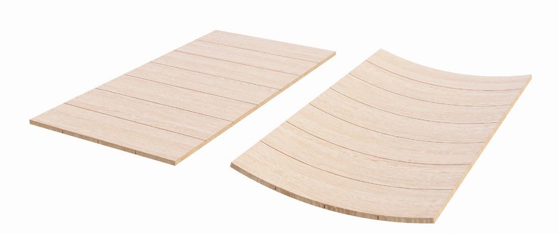
3.5. INTERPRETATION OF BATH ABBEY VA u LTS
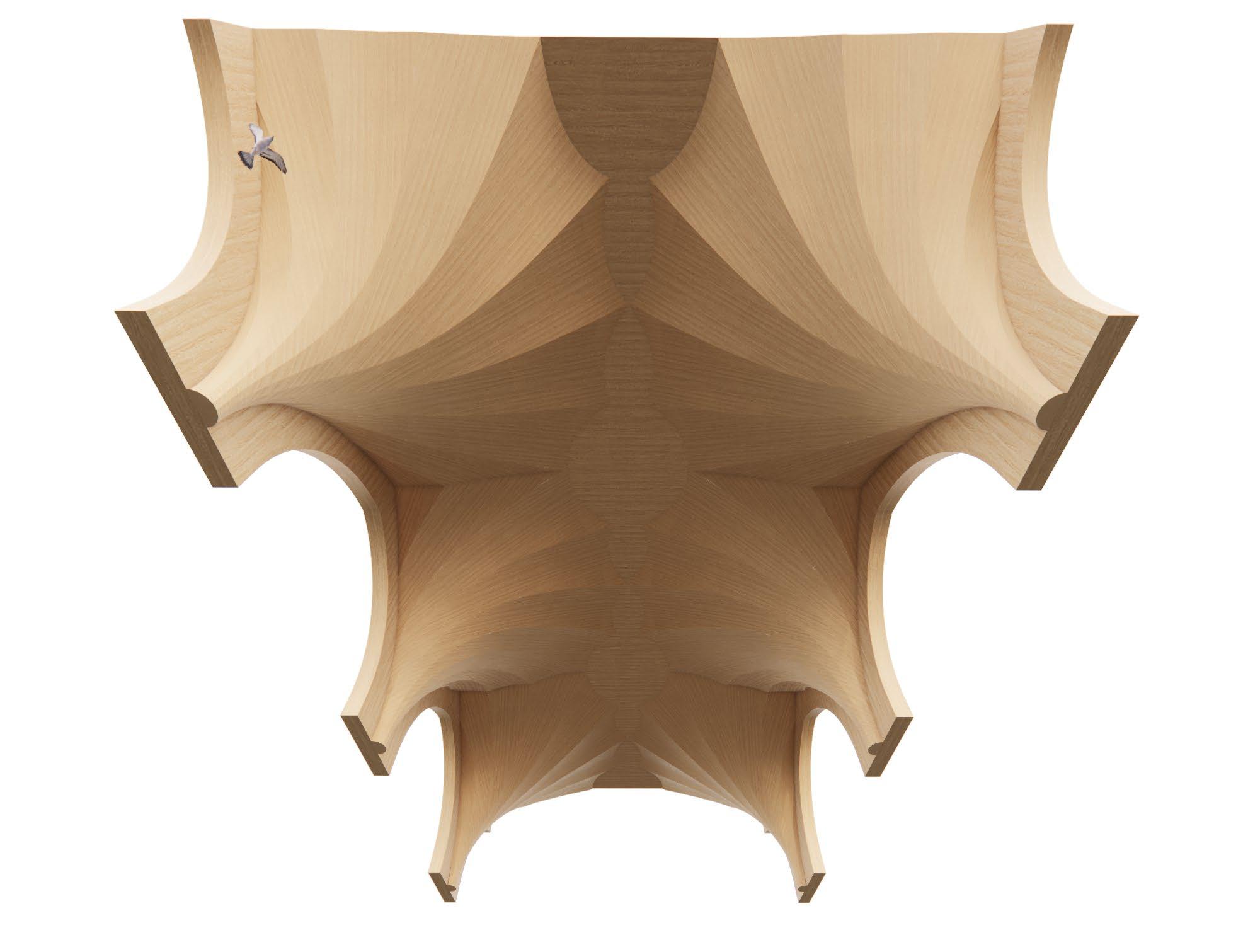
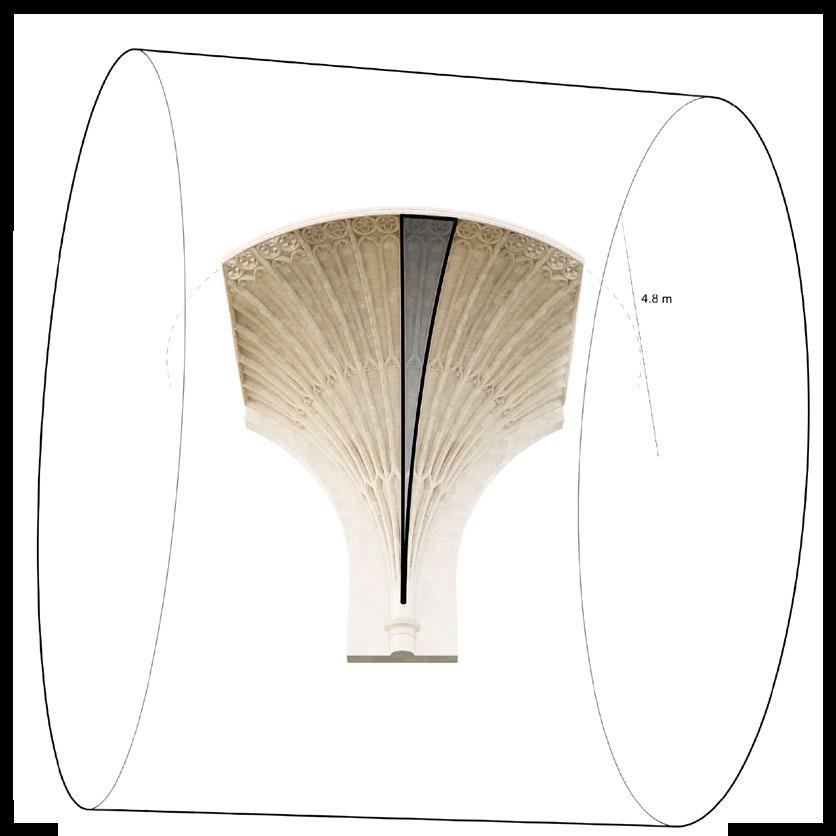
FOLLOWING THE METHOD OF URBACH TOWER
52 - A PPEN d IX
Cold Bend Locking layer
Spruce, 10 mm
WMC = 12%
Self Shaped Bi-Layers
Spruce, 10 mm
WMC = 12%
Spruce, 30 mm
WMC = 22%
53
3.6. INTERPRETATION OF BATH ABBEY VA u LTS
FOLLOWING THE METHOD OF WOOD MOULDING
54 - A PPEN d IX
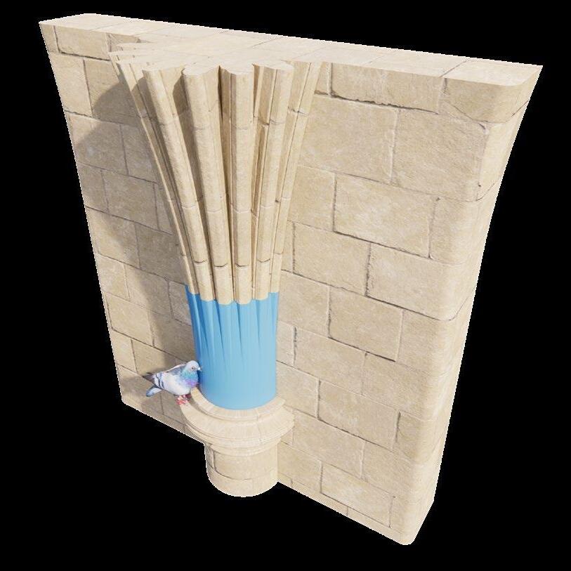
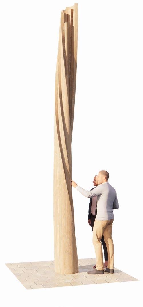
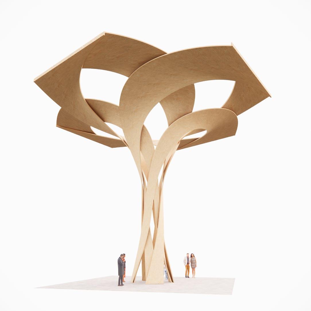
DESIGN SPECULATION - SPIRAL COLUMN
Single curved sheet
Moulded Wood
Inner radii:
R - 425 mm
R - 275 mm
R - 125 mm
55
3.7. PORTAL FRAME RE-IMAGINE d
SIngle curved timber sheet
R - 4100 mm; 50mm thick
R - 8130 mm; 50mm thick
not a constant curvature; 50mm thick
Flat sheet
R - ∞; 100mm thick
56 - A PPEN d IX
SIngle curved timber sheet
R - 4100 mm; 100mm thick
Planar timber sheet
R - ∞; 100mm thick
OR Better than
57
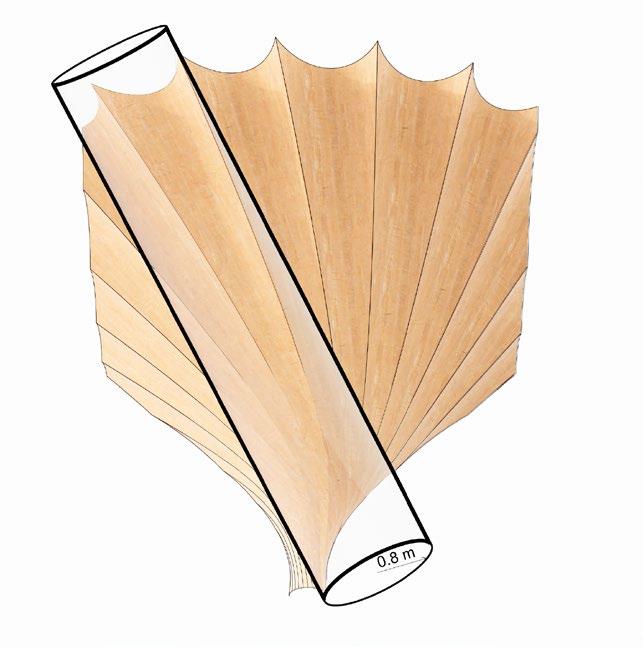
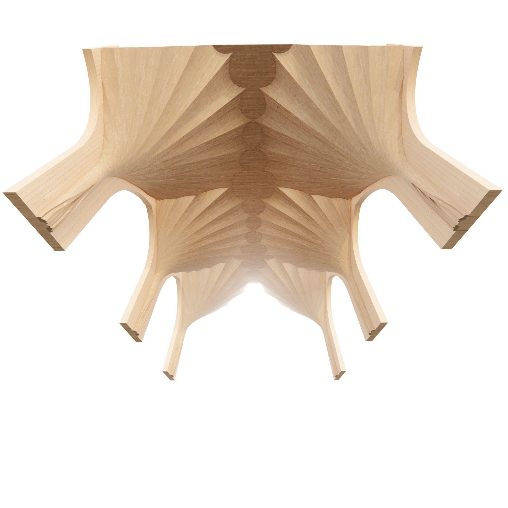
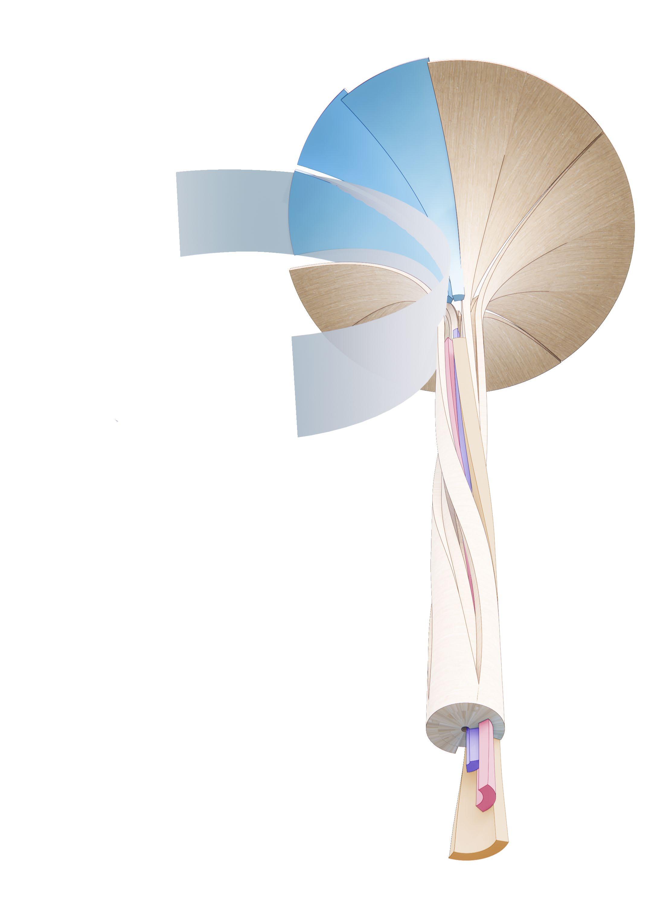
3.8. SEL-S u PPORTING CANOPIES
Single curved Sheets
R - 2238 mm
R - 6175 mm
R - 13231 mm
R - 4949 mm
R - 7529 mm
58 - A PPEN d IX
DOUBLE CURVED
59
All work produced by Unit 14
Unit book design by Charlie Harriswww.bartlett.ucl.ac.uk/architecture
Copyright 2021
The Bartlett School of Architecture, UCL All rights reserved.
No part of this publication may be reproduced or transmited in any form or by any means, electronic or mechanical, including photocopy, recording or any information storage and retreival system without permission in writing from the publisher.

-
@unit14_ucl UNIT
SPATIAL TECTONIC 2022

PG14 is a test bed for architectural exploration and innovation, examining the role of the architect in an environment of continuous change. We are in search of the new: leveraging technologies, workflows and modes of production seen in disciplines outside our own. We test ideas systematically by means of digital as well as physical drawings, models and prototypes. Our work evolves around technological speculation with a research-driven core, generating momentum through the astute synthesis of both. Our propositions are ultimately made through the design of buildings and in-depth consideration of structural formation and tectonic constituents. This, coupled with a strong research ethos, generates new and unprecedented, viable and spectacular proposals.
The focus of this year’s work evolved around the concept of ‘Spatial Tectonic’. This term describes architectural space as a result of the highest degree of synthesis of all underlying principles. Constructional logic, spatial innovation, typological organisation, and environmental and structural performance are all negotiated in an iterative process driven by architectural investigation. These inherent principles of organisational intelligence can be observed in both biotic and abiotic systems, in all spatial arrangements where it is critical for the overall performance of any developed order. Ultimately such principles suggest that the arrangement of constituents provides intelligence as well as advantage to the whole.
Through a deep understanding of architectural ingredients, students generated highly developed architectural systems in which spatial organisation arose as a result of sets of mutual interactions. These interactions were understood through targeted iterations of spatial models, uncovering logical links while generating ambitious and speculative arrangements. Sequential testing and the enriching of abstract yet architectural systems were the basis of architectural form - communicating the relationship of all logical dependencies, roles and performances within the system.

UNIT 14 @unit14_ucl All work produced by Unit 14 Unit book design by Charlie Harriswww.bartlett.ucl.ac.uk/architecture Copyright 2021 The Bartlett School of Architecture, UCL All rights reserved.No part of this publication may be reproduced or transmitted in any form or by any means, electronic or mechanical, including photocopy, recording or any information storage and retreival system without permission in writing from the publisher.
Thanks to: ARUP, ALA, DKFS, knippershelbig, RSHP, HASSELL, Seth Stein Architects, ZHA, Expedition Engineering
